EP3505907B1 - Testing device - Google Patents
Testing device Download PDFInfo
- Publication number
- EP3505907B1 EP3505907B1 EP18150098.4A EP18150098A EP3505907B1 EP 3505907 B1 EP3505907 B1 EP 3505907B1 EP 18150098 A EP18150098 A EP 18150098A EP 3505907 B1 EP3505907 B1 EP 3505907B1
- Authority
- EP
- European Patent Office
- Prior art keywords
- drive
- spindle
- eccentric
- eccentric transmission
- testing device
- Prior art date
- Legal status (The legal status is an assumption and is not a legal conclusion. Google has not performed a legal analysis and makes no representation as to the accuracy of the status listed.)
- Active
Links
- 238000012360 testing method Methods 0.000 title claims description 147
- 230000008878 coupling Effects 0.000 claims description 50
- 238000010168 coupling process Methods 0.000 claims description 50
- 238000005859 coupling reaction Methods 0.000 claims description 50
- 230000005540 biological transmission Effects 0.000 claims description 35
- 230000008859 change Effects 0.000 claims description 24
- 238000006073 displacement reaction Methods 0.000 claims description 6
- 230000009466 transformation Effects 0.000 claims 2
- 238000006243 chemical reaction Methods 0.000 description 18
- 238000013461 design Methods 0.000 description 16
- 230000003134 recirculating effect Effects 0.000 description 10
- 239000013598 vector Substances 0.000 description 10
- 230000000875 corresponding effect Effects 0.000 description 5
- 238000005096 rolling process Methods 0.000 description 5
- 230000007246 mechanism Effects 0.000 description 3
- 230000003068 static effect Effects 0.000 description 3
- 230000009471 action Effects 0.000 description 2
- 238000005452 bending Methods 0.000 description 2
- 230000001419 dependent effect Effects 0.000 description 2
- 238000011161 development Methods 0.000 description 2
- 230000018109 developmental process Effects 0.000 description 2
- 230000000694 effects Effects 0.000 description 2
- 210000003746 feather Anatomy 0.000 description 2
- 229910000831 Steel Inorganic materials 0.000 description 1
- 230000001154 acute effect Effects 0.000 description 1
- 238000013459 approach Methods 0.000 description 1
- 238000012790 confirmation Methods 0.000 description 1
- 238000010276 construction Methods 0.000 description 1
- 230000002596 correlated effect Effects 0.000 description 1
- 238000013016 damping Methods 0.000 description 1
- 229920001971 elastomer Polymers 0.000 description 1
- 239000000806 elastomer Substances 0.000 description 1
- 230000010354 integration Effects 0.000 description 1
- 238000012423 maintenance Methods 0.000 description 1
- 230000009467 reduction Effects 0.000 description 1
- 230000002787 reinforcement Effects 0.000 description 1
- 239000010959 steel Substances 0.000 description 1
Images


Classifications
-
- G—PHYSICS
- G01—MEASURING; TESTING
- G01N—INVESTIGATING OR ANALYSING MATERIALS BY DETERMINING THEIR CHEMICAL OR PHYSICAL PROPERTIES
- G01N3/00—Investigating strength properties of solid materials by application of mechanical stress
- G01N3/32—Investigating strength properties of solid materials by application of mechanical stress by applying repeated or pulsating forces
-
- F—MECHANICAL ENGINEERING; LIGHTING; HEATING; WEAPONS; BLASTING
- F16—ENGINEERING ELEMENTS AND UNITS; GENERAL MEASURES FOR PRODUCING AND MAINTAINING EFFECTIVE FUNCTIONING OF MACHINES OR INSTALLATIONS; THERMAL INSULATION IN GENERAL
- F16C—SHAFTS; FLEXIBLE SHAFTS; ELEMENTS OR CRANKSHAFT MECHANISMS; ROTARY BODIES OTHER THAN GEARING ELEMENTS; BEARINGS
- F16C19/00—Bearings with rolling contact, for exclusively rotary movement
- F16C19/54—Systems consisting of a plurality of bearings with rolling friction
- F16C19/55—Systems consisting of a plurality of bearings with rolling friction with intermediate floating or independently-driven rings rotating at reduced speed or with other differential ball or roller bearings
-
- F—MECHANICAL ENGINEERING; LIGHTING; HEATING; WEAPONS; BLASTING
- F16—ENGINEERING ELEMENTS AND UNITS; GENERAL MEASURES FOR PRODUCING AND MAINTAINING EFFECTIVE FUNCTIONING OF MACHINES OR INSTALLATIONS; THERMAL INSULATION IN GENERAL
- F16C—SHAFTS; FLEXIBLE SHAFTS; ELEMENTS OR CRANKSHAFT MECHANISMS; ROTARY BODIES OTHER THAN GEARING ELEMENTS; BEARINGS
- F16C3/00—Shafts; Axles; Cranks; Eccentrics
- F16C3/04—Crankshafts, eccentric-shafts; Cranks, eccentrics
- F16C3/18—Eccentric-shafts
-
- F—MECHANICAL ENGINEERING; LIGHTING; HEATING; WEAPONS; BLASTING
- F16—ENGINEERING ELEMENTS AND UNITS; GENERAL MEASURES FOR PRODUCING AND MAINTAINING EFFECTIVE FUNCTIONING OF MACHINES OR INSTALLATIONS; THERMAL INSULATION IN GENERAL
- F16C—SHAFTS; FLEXIBLE SHAFTS; ELEMENTS OR CRANKSHAFT MECHANISMS; ROTARY BODIES OTHER THAN GEARING ELEMENTS; BEARINGS
- F16C3/00—Shafts; Axles; Cranks; Eccentrics
- F16C3/04—Crankshafts, eccentric-shafts; Cranks, eccentrics
- F16C3/22—Cranks; Eccentrics
- F16C3/28—Adjustable cranks or eccentrics
-
- F—MECHANICAL ENGINEERING; LIGHTING; HEATING; WEAPONS; BLASTING
- F16—ENGINEERING ELEMENTS AND UNITS; GENERAL MEASURES FOR PRODUCING AND MAINTAINING EFFECTIVE FUNCTIONING OF MACHINES OR INSTALLATIONS; THERMAL INSULATION IN GENERAL
- F16H—GEARING
- F16H21/00—Gearings comprising primarily only links or levers, with or without slides
- F16H21/10—Gearings comprising primarily only links or levers, with or without slides all movement being in, or parallel to, a single plane
- F16H21/16—Gearings comprising primarily only links or levers, with or without slides all movement being in, or parallel to, a single plane for interconverting rotary motion and reciprocating motion
- F16H21/18—Crank gearings; Eccentric gearings
- F16H21/20—Crank gearings; Eccentric gearings with adjustment of throw
-
- F—MECHANICAL ENGINEERING; LIGHTING; HEATING; WEAPONS; BLASTING
- F16—ENGINEERING ELEMENTS AND UNITS; GENERAL MEASURES FOR PRODUCING AND MAINTAINING EFFECTIVE FUNCTIONING OF MACHINES OR INSTALLATIONS; THERMAL INSULATION IN GENERAL
- F16H—GEARING
- F16H25/00—Gearings comprising primarily only cams, cam-followers and screw-and-nut mechanisms
- F16H25/18—Gearings comprising primarily only cams, cam-followers and screw-and-nut mechanisms for conveying or interconverting oscillating or reciprocating motions
- F16H25/20—Screw mechanisms
- F16H25/22—Screw mechanisms with balls, rollers, or similar members between the co-operating parts; Elements essential to the use of such members
- F16H25/2204—Screw mechanisms with balls, rollers, or similar members between the co-operating parts; Elements essential to the use of such members with balls
-
- G—PHYSICS
- G01—MEASURING; TESTING
- G01N—INVESTIGATING OR ANALYSING MATERIALS BY DETERMINING THEIR CHEMICAL OR PHYSICAL PROPERTIES
- G01N2203/00—Investigating strength properties of solid materials by application of mechanical stress
- G01N2203/003—Generation of the force
- G01N2203/0032—Generation of the force using mechanical means
- G01N2203/0037—Generation of the force using mechanical means involving a rotating movement, e.g. gearing, cam, eccentric, or centrifuge effects
Definitions
- the present invention relates to a test device.
- the test device is used to load a test object with a dynamic test load.
- the test item can be any desired workpiece or component, for example a component of a motor vehicle such as a camshaft.
- the dynamic test load is preferably a test load that oscillates at a fixed or variable frequency, in particular sinusoidally, the mean value of which can be zero or can deviate from zero.
- the test load is, for example, a translational test path with which the test object is moved in the manner of a "shaker".
- an oscillating test path generated in the test device is converted into a test pivoting via a suitable drive or gear connection.
- the dynamic test load is preferably a test force with a predetermined effective direction or a test moment, in particular a bending moment or a torsion moment.
- a generated test path or a generated test pivot can be converted into a force or into a bending moment or torsion moment by a spring element (for example a coiled spring, a spring rod, a leaf spring, a torsion spring, an elastomer spring, etc.).
- the test path or the test pivoting can be applied to a spring base point of the spring element, while the other spring base point of the spring element is supported directly or indirectly on the test object.
- Test devices of the type presented here are used, for example, to examine the operational strength or fatigue strength of the test object (in particular fatigue strength and fatigue strength), to estimate a service life of the test object and / or for damage analysis.
- EP 2 179 263 B1 discloses a test device for testing a workpiece with a static and a superimposed dynamic test load.
- the workpiece is clamped by means of an upper and a lower clamping device, here with the interposition of a force transducer.
- a static test load is applied to the two clamping devices by means of a first actuator.
- a dynamic test load superimposed on the static test load is generated by means of a second actuator acting on the upper clamping device.
- the upper clamping device is guided for a translational movement in the direction of the test load.
- An actuating lever is pivotably articulated on the upper clamping device.
- a test device by means of which a workpiece is to be loaded with a dynamic test load.
- the amplitude of the test load should be adjustable without switching off the test device.
- a first drive drives an eccentric disk, the cylindrical outer circumference of which is rotatably guided in a bore of a second eccentric disk.
- a connecting rod is supported on the cylindrical outer surface of the second eccentric disk and is coupled to a clamping device for the workpiece via a cross head.
- the second eccentric disk Coaxially with the inner bore of the second eccentric disk, the second eccentric disk has a pinion which meshes with an internal toothing of a ring gear.
- the internal toothing of the ring gear is oriented concentrically to the drive axis of the first drive and the first eccentric disk.
- the ring gear is driven coaxially to this drive axle by means of a second drive. If the first drive drives the first eccentric disk and the second drive drives the ring gear at the same speed, the two eccentric disks and the ring gear rotate as a block.
- the connecting rod axis of the connecting rod bearing then moves on a circular path, the radius of which is dependent on the relative position of the two eccentric disks, resulting in a translatory back and forth movement of the clamping device, the amplitude of which corresponds to the radius mentioned.
- the amplitude can be changed by generating a relative rotation of the two eccentric disks, which can be done by generating a speed difference between the two drives on the short side.
- the first eccentric disk is driven directly by the first drive and the ring gear is also driven by the first drive with the interposition of a double planetary gear.
- a web of the double planetary gear is driven by the second drive.
- the double planetary gear is designed in such a way that the first eccentric disk and the ring gear are driven at the same speed for the stationary second drive and thus the stationary web, which results in a constant amplitude for the translational movement of the clamping device.
- the second drive is only actuated to adjust an amplitude of the movement of the clamping device.
- More in DE 20 2005 004 393 U1 Embodiments described are dedicated to the most complete possible mass balancing to enable high test frequencies as well as the integration of the eccentric drive in a test device, by means of which variable directions of force action can be implemented for the workpiece to be tested.
- WO 2011/076218 A1 discloses a test device in which a translational loading is also generated by means of a connecting rod which is driven by an eccentric sleeve.
- the eccentric sleeve is rotatably coupled here to a drive shaft.
- the eccentricity of the eccentric sleeve is adjusted in that a transmission pin, inclined at an acute angle of, for example, 5 to 15 °, is non-rotatably supported on the drive shaft, which is received with a positive fit in the circumferential direction in an inner bore of the eccentric sleeve.
- a translational movement of the eccentric sleeve relative to the eccentric pin can be brought about by means of an actuator, which movement leads to a change in the eccentricity according to the inclination of the eccentric pin.
- the eccentricity is adjusted in the range from 0 to 2.5 mm.
- DE 41 10 195 A1 is not of the generic type and discloses an adjusting device for a camshaft, by means of which a relative adjustment between a camshaft and a drive wheel is to be made possible.
- a sleeve-like extension of the drive wheel is equipped with internal splines.
- a camshaft gear which is connected to the camshaft in a rotationally fixed manner, has an external spline, the camshaft being mounted coaxially to the drive gear.
- the adjusting element is axially displaceable and has an internal thread, with which the adjusting element forms a type of spindle nut.
- a rotor of an electric motor has a spindle shaft, the external thread of which is screwed to the internal thread of the spindle nut.
- WO 2013/171322 A1 is not of the generic type and discloses a camshaft unit with two camshafts.
- the camshafts are arranged concentrically to one another, so that a first camshaft is arranged within a second camshaft.
- An adjusting element has a hollow shaft which has a first helical toothing on the inside and a second helical toothing on the inside and axially spaced therefrom and also on the inside.
- the first helical toothing of the adjusting element engages in a corresponding external first helical toothing of the first camshaft.
- the second helical toothing of the adjusting element engages in a corresponding external second helical toothing of the two camshafts.
- the adjusting element is firmly connected to a non-rotatably held spindle nut which runs on a spindle. By turning the spindle, the adjusting element is displaced axially via the spindle nut. Since the mutually interacting helical gears have different pressure angles, the axial movement of the adjusting element causes a relative rotation of the two camshafts.
- the test device has a drive which generates a rotational movement and which is preferably an electrical drive unit.
- the power flow from the drive of the test device runs via an eccentric gear.
- the eccentric gear is in drive connection (directly or indirectly with the interposition of gear elements) with the drive so that the eccentric gear is rotated by the drive at a drive speed about a drive axis.
- the drive speed can correspond to the drive speed of the drive or deviate from this if a gear element is interposed.
- the eccentric gear has an eccentric output element, via which an output from the eccentric gear to the test object takes place in order to generate the dynamic test load.
- the eccentric output element is a drive pin moved on a circular path, on which a drive connecting rod is rotatably mounted, the end region of which, facing away from the drive pin, carries out a dynamic test path.
- the eccentric gear used according to the invention has a first eccentric element.
- the first eccentric element is rotatably mounted about the drive axis of the eccentric gear.
- the first eccentric element has a bearing surface.
- This storage area can be a act outer cylindrical shell surface. It is preferably an inner, hollow-cylindrical inner bearing surface.
- the bearing axis of the bearing surface is arranged eccentrically to the drive axis with an eccentricity e 1.
- the eccentric gear has a second eccentric element.
- the second eccentric element is supported rotatably about the bearing axis with respect to the bearing surface of the first eccentric element. This is preferably done with the interposition of a sliding or roller bearing between the two eccentric elements.
- the eccentric gear has an adjustment device.
- a relative angle of rotation of the eccentric elements can be changed by means of the adjusting device.
- the adjustment device is based on the use of an additional electric drive used in addition to the aforementioned electric drive, with both drives then applying a speed to the two eccentric elements so that they rotate in the block for a dynamic test load with constant amplitude, while for adjustment of the
- the amplitude of the dynamic test load has to be influenced in a targeted manner on the phase position and / or the speed of the two electric drives.
- the two electric drives must be able to generate and maintain an exactly correlated phase position of the two eccentric elements, even if considerable oscillating loads may act on the eccentric elements as a result of the test loads.
- the adjustment device has an actuator, by means of which a translational adjustment path of a drive element of the eccentric gear can be generated (and by means of which, in particular, an adjustment path once brought about can also be maintained) .
- the actuator can directly generate the translational adjustment path of the drive element.
- the actuator can be coupled to a lever part of a pivotably mounted actuating lever, while the drive element can be coupled to the other lever part of the actuating lever.
- a conversion gear is also present in the test device according to the invention.
- the conversion gear converts the translational adjustment path of the drive element generated by the actuator into an adjustment angle of rotation of an output element.
- the drive element and the output element are coupled to the eccentric elements in such a way that the adjustment angle of rotation correlates with a change in the relative angle of rotation of the eccentric elements, so that in this way a change in the amplitude of the dynamic test load can be brought about.
- a linear drive to generate a translational adjustment path of a drive element, the drive element being coupled to the second eccentric element in a rotationally fixed manner.
- the conversion gear can convert the translational adjustment path into an adjustment angle of rotation of the output element, which here can be designed directly as the first eccentric element or can be coupled to it in a rotationally fixed manner.
- the adjustment rotation angle generated by the conversion gear corresponds directly to the change in the relative rotation angle of the eccentric elements.
- a translational actuator or linear drive can also be used to cause a change in the amplitude of the dynamic test load.
- a control or regulation of the actuator according to the invention can be simplified here, since the actuator only has to maintain a brought about translational adjustment path after an adjustment that has been brought about, without complex control or regulation of a phase position of two rotary drives being required, as in accordance with the state of the art (here DE 20 2005 004 393 U1 ) is required.
- the conversion gear has a spindle drive.
- the spindle forms the drive element.
- the spindle is mounted so as to be axially movable. Since the spindle rotates in accordance with the second eccentric element, the spindle is also rotatably mounted.
- the spindle nut of the spindle drive forms the output element, so that the spindle nut is coupled to the first eccentric element in a rotationally fixed manner.
- the spindle nut is rotatably mounted in order to be able to rotate with the first eccentric element.
- the spindle nut is not mounted or supported so that it can move axially.
- the spindle drive there are many possibilities for the structural design of the spindle drive. For example, it is not absolutely necessary for the spindle drive to enable relative angles of rotation between the spindle and the spindle nut over several revolutions. Rather, it is sufficient if the spindle drive enables a relative angle of rotation of the spindle and the spindle nut that corresponds to the desired adjustment angle of rotation and thus the change in the relative angle of rotation of the eccentric elements and ultimately the desired change in the amplitude of the dynamic test load.
- the spindle drive can also only allow a relative angle of rotation of 180 ° or even less.
- a thread or a thread groove of the spindle nut for example with regard to the thread or groove geometry and / or a pitch and any engagement element between spindle and spindle nut
- any embodiments known to those skilled in the art can be used within the scope of the invention.
- the spindle drive is designed as a recirculating ball screw drive.
- the use of such a recirculating ball screw drive is characterized by low friction, which results in a high degree of efficiency for the actuation of the adjustment device.
- a pretensioned design of the recirculating ball screw drive is also possible, resulting in a backlash-free design of the spindle drive, which is particularly advantageous in view of the dynamic test load or any alternating load.
- the spindle is coupled to the second eccentric element via a coupling element for a further proposal of the invention.
- This coupling element transmits the rotational movement of the spindle, but does not transmit the translational adjustment path of the spindle.
- a shaft-hub connection with axial engagement but form fit in the circumferential direction is used as the coupling element, for example a connection via a transverse pin extending into an axial groove, a connection via a feather key extending into an axial groove, a connection via a splined shaft or a toothed shaft, a connection via a serrated tooth profile or a polygonal profile, in which case a positive fit in the circumferential direction is preferably free of play, which can be achieved by pretensioning in the circumferential direction.
- Recirculating ball screw drives are also referred to as ball screw drives, with possible configurations that can be used within the scope of the invention also being described and standardized in the ISO 3408-01 standard.
- roller screw drive it is also possible that a so-called roller screw drive is used.
- clutches with rolling elements such as balls or rollers, are used for the said coupling element, the rolling elements enabling an axial movement of the spindle relative to the second eccentric element, in which the rolling elements along at least one groove of the spindle and / or the second eccentric element can roll, while the rolling elements create a rotationally fixed connection between the spindle and the second eccentric element in the circumferential direction.
- a pretensioned, play-free configuration of such a coupling element based on rolling elements is also possible here.
- the spindle is coupled to the second eccentric element via a coupling element.
- This coupling element transmits a rotary movement of the spindle to the second eccentric element.
- this coupling element compensates for the eccentricity e 1 between the rotation of the second eccentric element about the bearing axis and the rotation of the spindle about the drive axis.
- this coupling element can be designed in any way.
- this coupling element can be a cardan shaft with two cardan joints in a Z arrangement.
- the coupling element is a coupling with a drive disk connected non-rotatably to the spindle and an output disk connected non-rotatably to the second eccentric element as well as an intermediate disk.
- the intermediate disk is connected to the drive disk via first coupling rods distributed over the circumference, while the intermediate disk on the other side is connected to the output disk via second coupling rods also distributed over the circumference.
- the actuator actuates a translationally moved drive body.
- the drive body is coupled to the spindle via a bearing unit, in particular a roller bearing.
- the bearing unit transmits the translational movement of the drive body, which can be the translational adjustment path, but enables a relative rotation of the spindle with respect to the drive body. In this way it can be ensured that the spindle rotates during the test operation of the test device in accordance with the drive by the electric drive, while the actuator only has to maintain a position of the drive body in the test operation.
- the invention proposes that a compensating element be arranged between the actuator (and in particular between the aforementioned bearing unit).
- the compensating element transmits the translational movement of the actuator, but the compensating element can compensate for a radial offset or an angular error of the active axis of the actuator and the drive axis about which the spindle rotates.
- the test load transmitted via the eccentric elements acts on the spindle and thus the spindle drive.
- an adjusting force or holding force applied by the actuator also acts on the spindle.
- the spindle and the spindle drive can be exposed to considerable loads, whereby it has been found (especially for the design of the spindle drive as a recirculating ball screw drive or a roller screw drive) that a radial offset or an angular error of the active axis of the actuator with respect to the drive axis becomes clear can lead to reduced service life of the spindle drive used. This reduction in service life can be counteracted by using the compensation element.
- the compensating element can be designed as a flexible actuating rod, one end area of which is coupled to the spindle, while the other end area is moved in a translatory manner by the actuator with the adjustment path.
- the first eccentric element is formed by a (one-part or multi-part) eccentric housing or is connected to it.
- the adjustment device, the spindle drive, the recirculating ball screw drive or the recirculating roller screw drive, the aforementioned coupling element which transmits a rotational movement of the spindle but does not transmit the translational adjustment path of the spindle, the aforementioned coupling element can then be at least partially inside the eccentric housing , which transmits a rotary movement of the spindle and compensates for the eccentricity e 1 between the bearing axis and the drive axis, the second eccentric element and / or roller bearings, via which the second eccentric element is rotatably mounted on the bearing surface of the first eccentric element, can be arranged Any number or all of the aforementioned components can be arranged in the interior of the eccentric housing.
- the eccentric housing can be designed as a housing closed in the circumferential direction, or at least partially have openings, the eccentric housing also (at least apart from the first eccentric element) being distributed in a cage-like manner or distributed in the circumferential direction arranged housing struts can be formed, which can connect the first eccentric element to the spindle nut.
- the drive of the test device which is preferably an electric drive motor for generating a rotary movement, can be designed as desired and rotate any component of the eccentric gear.
- the drive is preferably in drive connection with a drive wheel of the eccentric gear via a belt.
- the use of a belt of this type has proven to be advantageous in terms of running smoothness, and the drive via the belt can also be designed to be free of play.
- the use of a belt for the drive has also proven to be low-maintenance. While the belt may have a low elasticity due to integrated reinforcements or steel cables, this may also be advantageous in view of its vibration-damping effect.
- the drive wheel of the eccentric gear can be arranged at any point on the eccentric gear. It is possible that the drive wheel is carried by the aforementioned eccentric housing or receives the eccentric housing in an inner bore.
- the drive wheel driven by the belt can be arranged, for example, in an axial region between the first eccentric element and the spindle nut.
- first eccentric element, the eccentric housing or a drive connection of the first eccentric element and the second eccentric element or a drive connection of the second eccentric element extend from the inside of the drive wheel.
- a drive pin for a drive connecting rod with an eccentricity e 2 with respect to the bearing axis of the second eccentric element is preferably arranged.
- the actuator is arranged to the side of the eccentric gear and / or the drive is arranged above the eccentric gear.
- the eccentric gear can be coupled to the laterally arranged actuator via a pivot lever.
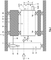
- Fig. 1 shows a highly schematic part of a test device 1.
- an eccentric gear 2 is driven via a conversion gear 3.
- the conversion gear 3 is driven with a drive speed and a drive torque 4 via a drive (not shown here).
- the eccentric gear 2 has two eccentric elements 5, 6.
- the eccentric element 5, which is also referred to here as the “first eccentric element”, is designed as an eccentric sleeve 7.
- An outer bearing surface 8 is cylindrical.
- the eccentric sleeve 7 is rotatably mounted on a housing 10 of the test device 1 via roller bearings 9a, 9b.
- a cylindrical inner surface of the bearing sleeve 8 is arranged eccentrically to the outer bearing surface 8 and forms an inner bearing surface 11.
- the eccentric sleeve 7 rotates as a result of the roller bearings 9a, 9b about a stationary drive axis 12, which corresponds to the longitudinal axis of the cylindrical outer bearing surface 8.
- the longitudinal axis of the cylindrical inner bearing surface 11 defines a bearing axis 13.
- the drive axis 12 and the bearing axis 13 are offset from one another with an eccentricity e 1.
- the second eccentric element 6 is rotatably mounted on the inner bearing surface 11 via roller bearings 14a, 14b, the second eccentric element 6 being designed as a cylindrical shaft 15.
- the shaft 15 can rotate about the bearing axis 13.
- the second eccentric element 6 With an eccentricity e 2 at a distance from the bearing axis 13, the second eccentric element 6 carries an eccentric output element 53 designed as a drive pin 16.
- the drive pin 16 defines a drive pin axis 17.
- the bearing axis 13 rotates about the drive axis 12, whereby the vector of the eccentricity e 1 also rotates in the plane which is oriented transversely to the drive axis 12.
- the vector of the eccentricity e 2 of the drive pin axis 17 also rotates with respect to the bearing axis 13.
- the vector of the total eccentricity E is thus obtained from the superposition of the vectors of the eccentricities e 1 , e 2 . If the two eccentric elements 5, 6 are driven at the same speed, so that they and the eccentric gear 2 rotate "in block", the amount of the vector of the total eccentricity E does not change, while the vector of the total eccentricity E rotates about the drive axis 12.
- the drive pin 16 serves to support a drive connecting rod 19, which is rotatably mounted in the area of a drive connecting rod eye on the drive pin 16, while the other end area of the drive connecting rod 19 is connected directly or indirectly to the test object and is preferably guided in a translatory manner according to the effective axis of the dynamic test load.
- an adjustment device 18 is used in the test device 1, which has the conversion gear 3.
- the conversion gear 3 is connected to the first eccentric element 5 via a first, non-rotatable drive connection 20, so that the circumferential gear 3 transmits the drive speed and the drive torque 4 from the drive to the first eccentric element 5.
- the conversion gear 3 transmits the drive speed and the drive torque 4 of the drive to the second eccentric element 6 via a further non-rotatable drive connection 21. Since the conversion gear 3 rotates around the drive axis 12, while the second eccentric element 6 rotates around the bearing axis 13, the non-rotatable drive connection 21 has a coupling element 22 which enables the drive movement to be transmitted despite the eccentricity e 1 (in particular without losing the synchronicity of the rotational movement of the conversion gear 3 and the second eccentric element 6).
- the coupling element 22 is, for example, a cardan shaft with two cardan joints in a Z arrangement or an offset compensating coupling with several disks coupled via coupling rods, as was explained at the beginning.
- the conversion gear 3 has a drive element 23, which is non-rotatably connected to the second eccentric element via the drive connection 21, as well as an output element 24, which is coupled to the first eccentric element 5 in a rotationally fixed manner via the drive connection 20.
- the relative position of the drive element 23 and the output element 24 is unchanged.
- there is a change in the relative position of the output element 24 with respect to the drive element 23 for the adjustment operation which as a result of the drive connections 20, 21 results in a change in the relative position of the eccentric elements 5, 6 and thus a change in the amount of the total eccentricity E results.
- the change in the relative position of the output element 24 with respect to the drive element 23 is shown in FIG Fig. 1 marked schematically with an adjustment 25.
- FIG. 4 shows a schematic representation of a test device 1, but a more detailed representation has already been selected here than in FIG Fig. 1 .
- Fig. 2 are in terms of function and / or design according to the components Fig. 1 corresponding components are marked with the same designations and reference symbols.
- the eccentric gear 2 is essentially corresponding Fig. 1 formed with an eccentric sleeve 7 and a shaft 15 and drive pin 16 held thereon.
- the drive connecting rod 19, which is mounted on the drive pin 16 and generates a dynamic test load 26, can also be seen here.
- the conversion gear 3 of the adjusting device 18 is according to FIG Fig. 2 designed as a spindle drive 27, which in turn is designed as a recirculating ball screw drive 28.
- the spindle drive 27 has a spindle 29 and a spindle nut 30.
- the spindle 29 is coupled to the spindle nut 30 via rotating balls 31.
- the spindle nut 30 is non-rotatably coupled via the non-rotatable drive connection 20 and here rigidly coupled to the eccentric element 5.
- the eccentric element 5, the drive connection 20 and the spindle nut 30 form an elongated eccentric housing 32 in which, as will be explained below, further components of the eccentric gear 2 and the drive connection 21 are arranged.
- a drive 33 in particular an electric drive motor, is used to drive a drive wheel 35 via a belt 34.
- the drive wheel 35 is supported or formed by the outer surface of the eccentric housing 32, this preferably taking place approximately in the middle between the eccentric gear 2 and the spindle nut 30.
- the spindle 29 On the side facing away from the eccentric gear 2, the spindle 29 is rigidly connected to a compensating element 36, here a flexible but axially rigid actuating rod 37.
- a compensating element 36 On the side facing away from the spindle 29, the compensating element 36 is fastened to a coupling sleeve 38 which extends from the fastening location back in the direction of the spindle 29 and surrounds the compensating element 36 and the end region of the spindle 29.
- the coupling sleeve 38 is rotatably mounted inside a drive body 40 via a bearing unit 39, but is axially fixed.
- the drive body 40 can be moved parallel to the extent of the spindle 29 and parallel to the drive axis 12 via a translational adjustment path 42, which corresponds to the adjustment path 42 of the spindle 29 forming the drive element 23.
- a translational adjustment path 42 which corresponds to the adjustment path 42 of the spindle 29 forming the drive element 23.
- An axial offset and / or an angular error between the spindle 29 and the coupling sleeve 38, the bearing unit 39, the drive body 40 and the actuation direction of the actuator 41 can be compensated for by means of the compensating element 36.
- the spindle 29 is coupled to the eccentric element 6 via the coupling element 22.
- a further coupling element 43 is used in the drive connection 21 between the spindle 29 and the eccentric element 6. This coupling element 43 ensures a non-rotatable transmission of the rotational movement of the spindle 29 via the coupling element 22 to the eccentric element 6, while this coupling element 43 enables an axial displacement in the drive connection 21.
- this coupling element 43 can be designed, for example, as a splined shaft, polygon coupling, axially displaceable feather key connection or, as shown here, with balls or rollers guided in axial grooves, whereby a play-free form fit is preferably ensured in the circumferential direction.
- the operation of the test device 1 according to Fig. 2 is as follows: In the test mode with a constant amplitude of the dynamic test load 26, the actuator 41 is operated in such a way that the drive body 40 does not change its position. For this purpose, the actuator 41 can apply a sufficient holding force or a brake on the actuator 41 can also be actuated. As a result, the axial position of the spindle 29 with respect to the spindle nut 30 is also fixed, whereby the angle of rotation between the spindle 29 and the spindle nut 30 is also fixed.
- the relative angle of rotation of the eccentric elements 5, 6 is also fixed, which also results in a fixed, predetermined total eccentricity E with which the drive pin axis 17 rotates on a circular path around the drive axis 12.
- the drive connecting rod 19 generates a dynamic test load 26 with constant amplitude, which of the constant relative angle of rotation of the eccentric elements 5, 6 depends.
- the eccentric elements 5, 6, the eccentric housing 32, the spindle nut 30, the spindle 29, the coupling element 43 and the coupling element 22 rotate "in a block".
- the drive movement for these components rotating in the block is generated by driving the drive wheel 35 via the belt 34 by the drive 33.
- With the spindle 29, the compensating element 36 and the coupling sleeve 38 also rotate, whereby the rotational movement due to the bearing unit 39 does not affect the drive body 40 and the actuator 41 is transmitted.
- the actuator 41 In an adjustment mode, the actuator 41 generates an adjustment path 42 of the drive body 40.
- This adjustment path 42 of the drive body 40 is transmitted to the spindle 29 via the bearing unit 39, the coupling sleeve 38 and the compensating element 36.
- the resulting adjustment path 42 of the spindle 39 has the consequence that the relative angle of rotation between the spindle nut 30 and the spindle 29 changes in the spindle drive 27, whereby the relative angle of rotation of the eccentric elements 5, 6 also changes as a result of the drive connections 20, 21 changed, which is associated with an adjustment of the total eccentricity E and a change in the amplitude of the dynamic test load 26 results.
- the adjustment path 42 of the spindle 29 can be compensated for by an axial displacement in the drive connection 21 ensured by the coupling element 43.
- the adjustment path 42 of the spindle 29 is converted into an adjustment angle of rotation 44 by means of the spindle drive 27.
- Fig. 3 shows schematically the eccentric elements 5, 6 of the eccentric gear 2 in a position in which the total eccentricity E is minimal, namely zero. This corresponds to the in Fig. 2 The illustrated position of the eccentric gear 2. The result is a minimal eccentricity E min of zero, since the amounts of the eccentricities e 1 , e 2 are selected to be the same for this embodiment.
- the vectors of the eccentricities e 1 , e 2 are oriented in opposite directions, so that they cancel each other out.
- Fig. 5 shows a detail V according to Fig. 2 for realizing the eccentric gear 2 with the mounting of the eccentric elements 5, 6 via the roller bearings 9, 14.
- Fig. 6 shows a horizontal section through a structural design of the test device 1.
- the actuator 41 is arranged to the side of the eccentric gear 2.
- a drive body 45 of the actuator 41 is articulated to an actuating lever 46 which is pivotably mounted in a pivot bearing 47 on the housing 10.
- an actuating rocker 48 is articulated, which is pivotably connected to the drive body 40.
- the drive body 40 is corresponding Fig. 2 via a bearing unit 39, a coupling sleeve 38 and a compensating element 36 in FIG Fig. 6 Connected to the spindle 29 in a manner not shown.
- the adjustment path 42 of one lever part or the spindle 29 is reversed to an actuator path 49.
- the actuating lever 46 enables the actuator 41 to be arranged to the side of the eccentric gear 2, which results in a short design results.
- the adjustment path 42 can also be reduced or increased in relation to the actuator path 49, whereby the actuation forces and the actuation path of the actuator 41 can also be adapted.
- the eccentric housing 32 is not closed in the circumferential direction, but rather has openings 50 distributed over the circumference between the eccentric element 5 and the spindle nut 30.
- the eccentric housing 32 is formed with housing struts 51 which run in the axial direction and are distributed over the circumference, via which the eccentric element 5 and the spindle nut 30 are connected to one another and between which the openings 50 are formed.
- Fig. 7 shows a side view of the test device 1. It can be seen here that the drive 33 is arranged above the actuator 41, the actuating lever 46, the conversion gear 3 and the eccentric gear 2. The drive 33 is held on the upper side on the housing 10 of the test device 1. The housing 10 has a housing opening 52 on the upper side, through which the belt 34 extends into the interior of the housing 10 to the drive wheel 35 extends. It can also be seen in Fig. 7 that here the test specimen is arranged in the vertical direction like a tower in the clamping devices and is subjected to the dynamic test load 26 by the drive connecting rod 19.
- the drive pin 16 represents the eccentric output element 53.
- the eccentric output element 53 can, however, also be formed by an eccentric outer surface of the eccentric element 6, for example.
Description
Die vorliegende Erfindung betrifft eine Prüfvorrichtung. Mittels der Prüfvorrichtung erfolgt eine Belastung eines Prüflings mit einer dynamischen Prüfbelastung. Bei dem Prüfling kann es sich um ein beliebiges Werkstück oder Bauelement, beispielsweise ein Bauteil eines Kraftfahrzeugs wie eine Nockenwelle, handeln.The present invention relates to a test device. The test device is used to load a test object with a dynamic test load. The test item can be any desired workpiece or component, for example a component of a motor vehicle such as a camshaft.
Die dynamische Prüfbelastung ist vorzugsweise eine mit einer festen oder variablen Frequenz, insbesondere sinusförmig, oszillierende Prüfbelastung, deren Mittelwert Null sein kann oder von Null abweichen kann. Die Prüfbelastung ist beispielsweise ein translatorischer Prüfweg, mit welchem der Prüfling in der Art eines "Shakers" bewegt wird. Möglich ist aber auch, dass ein in der Prüfvorrichtung erzeugter oszillierender Prüfweg über eine geeignete Antriebs- oder Getriebeverbindung umgewandelt wird in eine Prüf-Verschwenkung. Vorzugsweise ist die dynamische Prüfbelastung eine Prüfkraft mit einer vorgegebenen Wirkrichtung oder ein Prüfmoment, insbesondere ein Biegemoment oder ein Torsionsmoment. Hierbei kann eine Umwandlung eines erzeugten Prüfwegs oder einer erzeugten Prüf-Verschwenkung in eine Kraft oder in ein Biegemoment oder Torsionsmoment durch ein Federelement (beispielsweise eine gewendelte Feder, einen Federstab, eine Blattfeder, eine Torsionsfeder, eine Elastomerfeder o. ä.) erfolgen. Dabei kann ein Federfußpunkt des Federelements mit dem Prüfweg oder der Prüf-Verschwenkung beaufschlagt werden, während der andere Federfußpunkt des Federelements unmittelbar oder mittelbar an dem Prüfling abgestützt ist.The dynamic test load is preferably a test load that oscillates at a fixed or variable frequency, in particular sinusoidally, the mean value of which can be zero or can deviate from zero. The test load is, for example, a translational test path with which the test object is moved in the manner of a "shaker". However, it is also possible that an oscillating test path generated in the test device is converted into a test pivoting via a suitable drive or gear connection. The dynamic test load is preferably a test force with a predetermined effective direction or a test moment, in particular a bending moment or a torsion moment. Here, a generated test path or a generated test pivot can be converted into a force or into a bending moment or torsion moment by a spring element (for example a coiled spring, a spring rod, a leaf spring, a torsion spring, an elastomer spring, etc.). The test path or the test pivoting can be applied to a spring base point of the spring element, while the other spring base point of the spring element is supported directly or indirectly on the test object.
Prüfvorrichtungen der hier vorliegenden Art finden Einsatz beispielsweise zur Untersuchung einer Betriebsfestigkeit oder Schwingfestigkeit des Prüflings (insbesondere Dauer- und Zeitfestigkeit), zur Abschätzung einer Lebensdauer des Prüflings und/oder zur Schadensanalyse.Test devices of the type presented here are used, for example, to examine the operational strength or fatigue strength of the test object (in particular fatigue strength and fatigue strength), to estimate a service life of the test object and / or for damage analysis.
Der vorliegenden Erfindung liegt die Aufgabe zugrunde, eine alternative konstruktive Gestaltung einer Prüfvorrichtung vorzuschlagen, welche insbesondere hinsichtlich
- der Dauerfestigkeit der Prüfvorrichtung infolge der Wechselbelastung,
- der Veränderung der Amplitude der dynamischen Prüfbelastung auch während des Betriebs der Prüfvorrichtung,
- der Gewährleistung, dass die auf den Prüfling von der Prüfvorrichtung aufgebrachte dynamische Prüfbelastung innerhalb vorgegebener Grenzen einer Soll-Prüfbelastung (hinsichtlich der Frequenz, der Amplitude und/oder eines möglichst sinusförmigen dynamischen Anteils der Prüfbelastung) und/oder
- des Verstellbereichs für die Amplitude der dynamischen Prüfbelastung
- the fatigue strength of the test device as a result of the alternating load,
- the change in the amplitude of the dynamic test load even during operation of the test device,
- ensuring that the dynamic test load applied to the test object by the test device is within specified limits of a target test load (with regard to frequency, amplitude and / or a dynamic component of the test load that is as sinusoidal as possible) and / or
- the adjustment range for the amplitude of the dynamic test load
Die Aufgabe der Erfindung wird erfindungsgemäß mit den Merkmalen des unabhängigen Patentanspruchs gelöst. Weitere bevorzugte erfindungsgemäße Ausgestaltungen sind den abhängigen Patentansprüchen zu entnehmen.The object of the invention is achieved according to the invention with the features of the independent claim. Further preferred embodiments according to the invention can be found in the dependent claims.
Die erfindungsgemäße Prüfvorrichtung verfügt über einen Antrieb, der eine Rotationsbewegung erzeugt und bei welchem es sich vorzugsweise um ein elektrisches Antriebsaggregat handelt. Von dem Antrieb der Prüfvorrichtung verläuft der Kraftfluss über ein Exzentergetriebe. Das Exzentergetriebe steht (unmittelbar oder mittelbar unter Zwischenschaltung von Getriebeelementen) mit dem Antrieb in Antriebsverbindung, so dass das Exzentergetriebe von dem Antrieb mit einer Antriebsdrehzahl um eine Antriebsachse verdreht wird. Hierbei kann die Antriebsdrehzahl der Antriebsdrehzahl des Antriebs entsprechen oder bei Zwischenordnung eines Getriebeelements von dieser abweichen.The test device according to the invention has a drive which generates a rotational movement and which is preferably an electrical drive unit. The power flow from the drive of the test device runs via an eccentric gear. The eccentric gear is in drive connection (directly or indirectly with the interposition of gear elements) with the drive so that the eccentric gear is rotated by the drive at a drive speed about a drive axis. Here, the drive speed can correspond to the drive speed of the drive or deviate from this if a gear element is interposed.
Das Exzentergetriebe weist ein Exzenter-Abtriebselement auf, über welches ein Abtrieb von dem Exzentergetriebe zu dem Prüfling zur Erzeugung der dynamischen Prüfbelastung erfolgt. Beispielsweise handelt es sich bei dem Exzenter-Abtriebselement um einen auf einer Kreisbahn bewegten Antriebszapfen, auf welchem drehbar ein Antriebspleuel gelagert ist, dessen dem Antriebszapfen abgewandter Endbereich einen dynamischen Prüfweg ausführt.The eccentric gear has an eccentric output element, via which an output from the eccentric gear to the test object takes place in order to generate the dynamic test load. For example, the eccentric output element is a drive pin moved on a circular path, on which a drive connecting rod is rotatably mounted, the end region of which, facing away from the drive pin, carries out a dynamic test path.
Das erfindungsgemäß eingesetzte Exzentergetriebe weist ein erstes Exzenterelement auf. Das erste Exzenterelement ist drehbar um die Antriebsachse des Exzentergetriebes gelagert. Das erste Exzenterelement weist eine Lagerfläche auf. Bei dieser Lagerfläche kann es sich um eine äußere zylindrische Mantelfläche handeln. Vorzugsweise handelt es sich um eine innere hohlzylindrische innere Lagerfläche. Die Lagerachse der Lagerfläche ist mit einer Exzentrizität e1 exzentrisch zu der Antriebsachse angeordnet.The eccentric gear used according to the invention has a first eccentric element. The first eccentric element is rotatably mounted about the drive axis of the eccentric gear. The first eccentric element has a bearing surface. This storage area can be a act outer cylindrical shell surface. It is preferably an inner, hollow-cylindrical inner bearing surface. The bearing axis of the bearing surface is arranged eccentrically to the drive axis with an eccentricity e 1.
Das Exzentergetriebe weist ein zweites Exzenterelement auf. Das zweite Exzenterelement ist drehbar um die Lagerachse gegenüber der Lagerfläche des ersten Exzenterelements abgestützt. Dies erfolgt vorzugsweise unter Zwischenordnung eines Gleit- oder Wälzlagers zwischen den beiden Exzenterelementen.The eccentric gear has a second eccentric element. The second eccentric element is supported rotatably about the bearing axis with respect to the bearing surface of the first eccentric element. This is preferably done with the interposition of a sliding or roller bearing between the two eccentric elements.
Um eine Verstellung des Hubs oder der Amplitude der dynamischen Prüfbelastung herbeiführen zu können, weist das Exzentergetriebe eine Verstelleinrichtung auf. Mittels der Verstelleinrichtung ist ein relativer Drehwinkel der Exzenterelemente veränderbar.In order to be able to adjust the stroke or the amplitude of the dynamic test load, the eccentric gear has an adjustment device. A relative angle of rotation of the eccentric elements can be changed by means of the adjusting device.
In der erfindungsgemäßen Prüfvorrichtung sind zwei unterschiedliche Betriebsarten möglich:
- In einem Prüfbetrieb, in dem keine Veränderung der relativen Drehwinkel der Exzenterelemente durch die Verstelleinrichtung erfolgt, laufen die beiden Exzenterelemente "im Block um", was bedeuten soll, dass diese keine Relativbewegung zueinander unter Veränderung des relativen Drehwinkels ausführen. In diesem Prüfbetrieb erfolgt eine Prüfbelastung des Prüflings mit konstanter Amplitude der dynamischen Prüfbelastung.
- Des Weiteren ist ein Verstellbetrieb möglich, welcher außerhalb des Prüfbetriebs erfolgt oder auch in den Prüfbetrieb integriert sein kann. In diesem Verstellbetrieb erfolgt eine Veränderung der Amplitude der Prüfbelastung durch eine Betätigung der Verstelleinrichtung. Die Bestätigung der Verstelleinrichtung führt zu einer Veränderung des relativen Drehwinkels der Exzenterelemente. Diese Veränderung des relativen Drehwinkels der Exzenterelemente hat wiederum eine Veränderung der Amplitude der dynamischen Prüfbelastung des Prüflings zur Folge.
- In a test mode in which the relative rotation angle of the eccentric elements is not changed by the adjustment device, the two eccentric elements rotate "in block", which is intended to mean that they do not move relative to one another while changing the relative rotation angle. In this test mode, the test object is subjected to a test load with a constant amplitude of the dynamic test load.
- Furthermore, an adjustment operation is possible, which takes place outside of the test operation or can also be integrated into the test operation. In this adjustment mode, the amplitude of the test load is changed by actuating the adjustment device. Confirmation of the adjustment device leads to a change in the relative angle of rotation of the eccentric elements. This change in the relative angle of rotation of the eccentric elements in turn results in a change in the amplitude of the dynamic test load on the test object.
Für aus dem Stand der Technik bekannte Ausführungsformen (vgl.
Die Erfindung geht hier erstmals einen anderen Weg: Für die erfindungsgemäße Ausgestaltung weist die Verstelleinrichtung einen Aktuator auf, mittels dessen ein translatorischer Verstell-Weg eines Antriebselements des Exzentergetriebes erzeugt werden kann (und mittels dessen insbesondere auch ein einmal herbeigeführter Verstell-Weg gehalten werden kann). Hierbei kann im Rahmen der Erfindung der Aktuator unmittelbar den translatorischen Verstell-Weg des Antriebselements erzeugen. Möglich ist aber auch, dass zwischen den Aktuator und das Antriebselement eine beliebige getriebliche Verbindung zwischengeordnet ist. So kann beispielsweise der Aktuator mit einem Hebelteil eines verschwenkbar gelagerten Betätigungshebels gekoppelt sein, während das Antriebselement mit dem anderen Hebelteil des Betätigungshebels gekoppelt sein kann.The invention takes a different approach here for the first time: For the embodiment according to the invention, the adjustment device has an actuator, by means of which a translational adjustment path of a drive element of the eccentric gear can be generated (and by means of which, in particular, an adjustment path once brought about can also be maintained) . Here, within the scope of the invention, the actuator can directly generate the translational adjustment path of the drive element. However, it is also possible for any gear connection to be interposed between the actuator and the drive element. For example, the actuator can be coupled to a lever part of a pivotably mounted actuating lever, while the drive element can be coupled to the other lever part of the actuating lever.
In der erfindungsgemäßen Prüfvorrichtung ist des Weiteren ein Umwandlungsgetriebe vorhanden. Das Umwandlungsgetriebe wandelt den translatorischen, von dem Aktuator erzeugten Verstell-Weg des Antriebselements um in einen Verstell-Drehwinkel eines Abtriebselements. Erfindungsgemäß sind das Antriebselement und das Abtriebselement derart mit den Exzenterelementen gekoppelt, dass der Verstell-Drehwinkel mit einer Veränderung des relativen Drehwinkels der Exzenterelemente korreliert, so dass auf diese Weise eine Veränderung der Amplitude der dynamischen Prüfbelastung herbeigeführt werden kann.A conversion gear is also present in the test device according to the invention. The conversion gear converts the translational adjustment path of the drive element generated by the actuator into an adjustment angle of rotation of an output element. According to the invention, the drive element and the output element are coupled to the eccentric elements in such a way that the adjustment angle of rotation correlates with a change in the relative angle of rotation of the eccentric elements, so that in this way a change in the amplitude of the dynamic test load can be brought about.
Die erfindungsgemäße Ausgestaltung soll anhand eines möglichen Ausführungsbeispiels erläutert werden, ohne dass eine Einschränkung der Erfindung auf dieses Ausführungsbeispiel erfolgen soll: Möglich ist, dass ein Linearantrieb einen translatorischen Verstell-Weg eines Antriebselements erzeugt, wobei das Antriebselement drehfest mit dem zweiten Exzenterelement gekoppelt ist. In diesem Fall kann das Umwandlungsgetriebe den translatorischen Verstell-Weg umwandeln in einen Verstell-Drehwinkel des Abtriebselements, welches hier unmittelbar als erstes Exzenterelement ausgebildet sein kann oder drehfest mit diesem gekoppelt sein kann. In diesem Fall entspricht der von dem Umwandlungsgetriebe erzeugte Verstell-Drehwinkel unmittelbar der Veränderung des relativen Drehwinkels der Exzenterelemente.The design according to the invention is to be explained using a possible exemplary embodiment, without restricting the invention to this exemplary embodiment: It is possible for a linear drive to generate a translational adjustment path of a drive element, the drive element being coupled to the second eccentric element in a rotationally fixed manner. In this case, the conversion gear can convert the translational adjustment path into an adjustment angle of rotation of the output element, which here can be designed directly as the first eccentric element or can be coupled to it in a rotationally fixed manner. In In this case, the adjustment rotation angle generated by the conversion gear corresponds directly to the change in the relative rotation angle of the eccentric elements.
Im Rahmen der Erfindung kommt somit eine andere Verstell-Mechanik und -Kinematik als für den Stand der Technik zum Einsatz. Es kann auch erstmals ein translatorischer Aktuator oder Linearantrieb eingesetzt werden, um eine Veränderung der Amplitude der dynamischen Prüfbelastung zu verursachen. Unter Umständen kann hier eine Steuerung oder Regelung des Aktuators erfindungsgemäß vereinfacht werden, da der Aktuator nach einer einmal herbeigeführten Verstellung lediglich einen herbeigeführten translatorischen Verstell-Weg halten muss, ohne dass eine komplexe Steuerung oder Regelung einer Phasenlage von zwei Drehantrieben erforderlich ist, wie dies gemäß dem Stand der Technik (hier
Für die Ausgestaltung des Umwandlungsgetriebes gibt es im Rahmen der Erfindung vielfältige Möglichkeiten. Gemäß einem Vorschlag der Erfindung weist das Umwandlungsgetriebe einen Spindeltrieb auf. In dem Spindeltrieb bildet die Spindel das Antriebselement. Um die Herbeiführung des translatorischen Verstell-Wegs der Spindel zu ermöglichen, ist die Spindel axial bewegbar gelagert. Da die Spindel entsprechend dem zweiten Exzenterelement rotiert, ist die Spindel darüber hinaus verdrehbar gelagert. Hingegen bildet die Spindelmutter des Spindeltriebs das Abtriebselement, so dass die Spindelmutter drehfest mit dem ersten Exzenterelement gekoppelt ist. Hierbei ist die Spindelmutter verdrehbar gelagert, um mit dem ersten Exzenterelement rotieren zu können. Um die Umwandlung der axialen Bewegung der Spindel in einen Verstell-Drehwinkel bzw. eine Veränderung des relativen Drehwinkels der Exzenterelemente durch den Spindeltrieb zu ermöglichen, ist die Spindelmutter nicht axial bewegbar gelagert oder abgestützt.For the design of the conversion gear, there are various possibilities within the scope of the invention. According to a proposal of the invention, the conversion gear has a spindle drive. In the spindle drive, the spindle forms the drive element. In order to enable the translational adjustment path of the spindle to be brought about, the spindle is mounted so as to be axially movable. Since the spindle rotates in accordance with the second eccentric element, the spindle is also rotatably mounted. In contrast, the spindle nut of the spindle drive forms the output element, so that the spindle nut is coupled to the first eccentric element in a rotationally fixed manner. Here, the spindle nut is rotatably mounted in order to be able to rotate with the first eccentric element. In order to enable the conversion of the axial movement of the spindle into an adjustment angle of rotation or a change in the relative angle of rotation of the eccentric elements by the spindle drive, the spindle nut is not mounted or supported so that it can move axially.
Für die konstruktive Ausgestaltung des Spindeltriebs gibt es vielfältige Möglichkeiten. So ist beispielsweise nicht zwingend erforderlich, dass der Spindeltrieb relative Drehwinkel zwischen Spindel und Spindelmutter über mehrere Umdrehungen ermöglicht. Vielmehr ist es ausreichend, wenn der Spindeltrieb einen relativen Drehwinkel der Spindel und der Spindelmutter ermöglicht, die den angestrebten Verstell-Drehwinkel und damit der Veränderung des relativen Drehwinkels der Exzenterelemente und letzten Endes der gewünschten Veränderung der Amplitude der dynamischen Prüfbelastung entspricht. So kann der Spindeltrieb auch nur einen relativen Drehwinkel von 180° oder sogar weniger ermöglichen. Hinsichtlich der konstruktiven Ausgestaltung beispielsweise des Gewindes oder einer Gewindenut der Spindelmutter, eines Gewindes oder einer Gewindenut der Spindel (beispielsweise hinsichtlich der Gewinde- oder Nutgeometrie und/oder einer Steigung und eines etwaigen Eingriffselements zwischen Spindel und Spindelmutter) können im Rahmen der Erfindung beliebige, dem Fachmann bekannte Ausführungsformen Einsatz finden.There are many possibilities for the structural design of the spindle drive. For example, it is not absolutely necessary for the spindle drive to enable relative angles of rotation between the spindle and the spindle nut over several revolutions. Rather, it is sufficient if the spindle drive enables a relative angle of rotation of the spindle and the spindle nut that corresponds to the desired adjustment angle of rotation and thus the change in the relative angle of rotation of the eccentric elements and ultimately the desired change in the amplitude of the dynamic test load. The spindle drive can also only allow a relative angle of rotation of 180 ° or even less. With regard to the structural design, for example of the thread or a thread groove of the spindle nut, a thread or a thread groove of the spindle (for example with regard to the thread or groove geometry and / or a pitch and any engagement element between spindle and spindle nut), any embodiments known to those skilled in the art can be used within the scope of the invention.
Für einen besonderen Vorschlag der Erfindung ist der Spindeltrieb als Kugelumlauf-Gewindetrieb ausgebildet. Der Einsatz eines derartigen Kugelumlauf-Gewindetriebs zeichnet sich durch eine kleine Reibung aus, womit sich ein hoher Wirkungsgrad für die Betätigung der Verstelleinrichtung ergibt. Möglich ist auch eine vorgespannte Ausgestaltung des Kugelumlauf-Gewindetriebs, woraus sich eine spielfreie Ausgestaltung des Spindeltriebs ergibt, die insbesondere angesichts der dynamischen Prüfbelastung oder auch einer etwaigen Wechsel-Belastung vorteilhaft ist.For a particular proposal of the invention, the spindle drive is designed as a recirculating ball screw drive. The use of such a recirculating ball screw drive is characterized by low friction, which results in a high degree of efficiency for the actuation of the adjustment device. A pretensioned design of the recirculating ball screw drive is also possible, resulting in a backlash-free design of the spindle drive, which is particularly advantageous in view of the dynamic test load or any alternating load.
Um trotz des für die Funktion des Spindeltriebs erforderlichen axialen Freiheitsgrads der Spindel die drehfeste Antriebsverbindung der Spindel mit dem zweiten Exzenterelement zu ermöglichen, ist für einen weiteren Vorschlag der Erfindung die Spindel über ein Kupplungselement mit dem zweiten Exzenterelement gekoppelt. Dieses Kupplungselement überträgt die Drehbewegung der Spindel, aber überträgt den translatorischen Verstell-Weg der Spindel nicht. Möglich ist hierbei beispielsweise, dass als Kupplungselement eine Wellen-Narben-Verbindung mit axialem Eingriff, aber Formschluss in Umfangsrichtung Einsatz findet, beispielsweise eine Verbindung über einen sich in eine axiale Nut erstreckenden Querstift, eine Verbindung über eine sich in eine axiale Nut erstreckende Passfeder, eine Verbindung über eine Keilwelle oder eine Zahnwelle, eine Verbindung über ein Kerbzahnprofil oder ein Polygonprofil, wobei hierbei vorzugsweise ein Formschluss in Umfangsrichtung spielfrei ausgebildet ist, was durch eine Vorspannung in Umfangsrichtung erzielt werden kann. Kugelumlauf-Gewindetriebe werden auch als Kugelgewindetriebe bezeichnet, wobei mögliche, im Rahmen der Erfindung einsetzbare Ausgestaltungen auch in der Norm ISO 3408-01 beschrieben und normiert sind. Möglich ist auch, dass ein sogenannter Rollenumlauf-Gewindetrieb Einsatz findet. Möglich ist aber auch, dass für das genannte Kupplungselement Kupplungen mit Wälzkörpern, wie Kugeln oder Rollen, Einsatz finden, wobei die Wälzkörper eine Axialbewegung der Spindel relativ zu dem zweiten Exzenterelement ermöglichen, in dem die Wälzkörper entlang mindestens einer Nut der Spindel und/oder des zweiten Exzenterelements abwälzen können, während die Wälzkörper eine drehfeste Verbindung zwischen der Spindel und dem zweiten Exzenterelement in Umfangsrichtung schaffen. Möglich ist auch hier eine vorgespannte, spielfreie Ausgestaltung eines derartigen, auf Wälzkörpern basierenden Kupplungselements.In order to enable the rotationally fixed drive connection of the spindle to the second eccentric element despite the axial degree of freedom of the spindle required for the function of the spindle drive, the spindle is coupled to the second eccentric element via a coupling element for a further proposal of the invention. This coupling element transmits the rotational movement of the spindle, but does not transmit the translational adjustment path of the spindle. It is possible here, for example, that a shaft-hub connection with axial engagement but form fit in the circumferential direction is used as the coupling element, for example a connection via a transverse pin extending into an axial groove, a connection via a feather key extending into an axial groove, a connection via a splined shaft or a toothed shaft, a connection via a serrated tooth profile or a polygonal profile, in which case a positive fit in the circumferential direction is preferably free of play, which can be achieved by pretensioning in the circumferential direction. Recirculating ball screw drives are also referred to as ball screw drives, with possible configurations that can be used within the scope of the invention also being described and standardized in the ISO 3408-01 standard. It is also possible that a so-called roller screw drive is used. However, it is also possible that clutches with rolling elements, such as balls or rollers, are used for the said coupling element, the rolling elements enabling an axial movement of the spindle relative to the second eccentric element, in which the rolling elements along at least one groove of the spindle and / or the second eccentric element can roll, while the rolling elements create a rotationally fixed connection between the spindle and the second eccentric element in the circumferential direction. A pretensioned, play-free configuration of such a coupling element based on rolling elements is also possible here.
Da die Lagerachse der Exzenterelemente einerseits und die Antriebsachse des Exzentergetriebes andererseits eine Exzentrizität e1 aufweist, ist eine Übertragung der Drehbewegung der Spindel um die Antriebsachse zu der Drehbewegung des ersten Exzenterelements um die Lagerachse mit einer Exzentrizität oder einem radialen Versatz erforderlich. Aus diesem Grund wird für eine mögliche Ausgestaltung der erfindungsgemäßen Prüfvorrichtung vorgeschlagen, dass die Spindel über ein Kupplungselement mit dem zweiten Exzenterelement gekoppelt ist. Dieses Kupplungselement überträgt eine Drehbewegung der Spindel zu dem zweiten Exzenterelement. Zusätzlich gleicht dieses Kupplungselement die Exzentrizität e1 zwischen der Verdrehung des zweiten Exzenterelements um die Lagerachse und der Verdrehung der Spindel um die Antriebsachse aus. Dieses Kupplungselement kann beliebig ausgebildet sein. Beispielsweise kann es sich bei diesem Kupplungselement um eine Kardanwelle mit zwei Kardangelenken in Z-Anordnung handeln. Für eine bevorzugte Ausgestaltung der Erfindung handelt es sich bei dem Kupplungselement um eine Kupplung mit einer drehfest mit der Spindel verbundenen Antriebsscheibe sowie eine drehfest mit dem zweiten Exzenterelement verbundene Abtriebsscheibe sowie einer Zwischenscheibe. Hierbei ist die Zwischenscheibe über erste, über den Umfang verteilte Kuppelstangen mit der Antriebsscheibe verbunden, während die Zwischenscheibe auf der anderen Seite über zweite, ebenfalls über den Umfang verteilte Kuppelstangen mit der Abtriebsscheibe verbunden ist. Je nach Schwenkwinkel der Kuppelstangen kann ein unterschiedlicher Axialversatz der Antriebsscheibe gegenüber der Abtriebsscheibe gewährleistet werden, wobei dennoch eine Synchronität der Übertragung der Drehbewegung von der Antriebsscheibe zu der Abtriebsscheibe gewährleistet ist. Hinsichtlich einer möglichen derartigen einsetzbaren Kupplung wird lediglich beispielhaft auf die als "Schmidt-Kupplung" (eingetragene Marke) bezeichnete Kupplung gemäß der website www.schmidt-kupplung.com verwiesen. Eine Kupplung eines derartigen Typs führt unter Umständen zu einem gegenüber dem Einsatz einer Kardanwelle also Kupplungselement reduzierten axialen Baugröße.Since the bearing axis of the eccentric element on the one hand and the drive axis of the eccentric gear on the other hand have an eccentricity e 1 , the rotational movement of the spindle around the drive axis must be transmitted to the rotational movement of the first eccentric element around the bearing axis with an eccentricity or a radial offset. For this reason it is proposed for a possible embodiment of the test device according to the invention that the spindle is coupled to the second eccentric element via a coupling element. This coupling element transmits a rotary movement of the spindle to the second eccentric element. In addition, this coupling element compensates for the eccentricity e 1 between the rotation of the second eccentric element about the bearing axis and the rotation of the spindle about the drive axis. This coupling element can be designed in any way. For example, this coupling element can be a cardan shaft with two cardan joints in a Z arrangement. For a preferred embodiment of the invention, the coupling element is a coupling with a drive disk connected non-rotatably to the spindle and an output disk connected non-rotatably to the second eccentric element as well as an intermediate disk. Here, the intermediate disk is connected to the drive disk via first coupling rods distributed over the circumference, while the intermediate disk on the other side is connected to the output disk via second coupling rods also distributed over the circumference. Depending on the swivel angle of the coupling rods, a different axial offset of the drive pulley with respect to the driven pulley can be ensured, whereby a synchronism of the transmission of the rotary movement from the drive pulley to the driven pulley is guaranteed. With regard to a possible coupling of this type that can be used, reference is made only by way of example to the coupling referred to as "Schmidt coupling" (registered trademark) on the website www.schmidt-kupplung.com. A coupling of this type may lead to a reduced axial size compared to the use of a cardan shaft, that is to say a coupling element.
Gemäß einer Weiterbildung der Erfindung betätigt der Aktuator einen translatorisch bewegten Antriebskörper. Der Antriebskörper ist über eine Lagereinheit, insbesondere ein Wälzlager, mit der Spindel gekoppelt. Die Lagereinheit überträgt die translatorische Bewegung des Antriebskörpers, bei welcher es sich um den translatorischen Verstell-Weg handeln kann, aber ermöglicht eine relative Verdrehung der Spindel gegenüber dem Antriebskörper. Auf diese Weise kann gewährleistet werden, dass die Spindel während des Prüfbetriebs der Prüfvorrichtung entsprechend dem Antrieb durch den elektrischen Antrieb rotiert, während der Aktuator in dem Prüfbetrieb ausschließlich eine eingenommene Position des Antriebskörpers halten muss.According to a further development of the invention, the actuator actuates a translationally moved drive body. The drive body is coupled to the spindle via a bearing unit, in particular a roller bearing. The bearing unit transmits the translational movement of the drive body, which can be the translational adjustment path, but enables a relative rotation of the spindle with respect to the drive body. In this way it can be ensured that the spindle rotates during the test operation of the test device in accordance with the drive by the electric drive, while the actuator only has to maintain a position of the drive body in the test operation.
Die Erfindung schlägt in weiterer Ausgestaltung vor, dass zwischen dem Aktuator (und insbesondere zwischen der vorgenannten Lagereinheit) ein Ausgleichselement angeordnet ist. Das Ausgleichselement überträgt die translatorische Bewegung des Aktuators, wobei das Ausgleichselement aber einen radialen Versatz oder einen Winkelfehler der Wirkachse des Aktuators und der Antriebsachse, um welche die Spindel rotiert, ausgleichen kann. Auf die Spindel und damit den Spindeltrieb wirkt einerseits die über die Exzenterelemente übertragene Prüfbelastung. Andererseits wirkt auf die Spindel auch eine von dem Aktuator aufgebrachte Verstellkraft oder Haltekraft. Somit kann die Spindel und der Spindeltrieb beträchtlichen Belastungen ausgesetzt sein, wobei sich (insbesondere für die Ausgestaltung des Spindeltriebs als Kugelumlauf-Gewindetrieb oder Rollenumlauf-Gewindetrieb) herausgestellt hat, dass ein radialer Versatz oder ein Winkelfehler der Wirkachse des Aktuators gegenüber der Antriebsachse zu einer deutlich reduzierten Lebensdauer des eingesetzten Spindeltriebs führen kann. Dieser Reduzierung der Lebensdauer kann durch Einsatz des Ausgleichselements entgegengewirkt werden. Für die konstruktive Ausgestaltung des Ausgleichselements gibt es vielfältige Möglichkeiten. Um lediglich ein Beispiel zu nennen, kann das Ausgleichselement als biegeweiche Betätigungsstange ausgebildet sein, deren einer Endbereich mit der Spindel gekoppelt ist, während der andere Endbereich von dem Aktuator mit dem Verstell-Weg translatorisch bewegt wird.In a further embodiment, the invention proposes that a compensating element be arranged between the actuator (and in particular between the aforementioned bearing unit). The compensating element transmits the translational movement of the actuator, but the compensating element can compensate for a radial offset or an angular error of the active axis of the actuator and the drive axis about which the spindle rotates. On the one hand, the test load transmitted via the eccentric elements acts on the spindle and thus the spindle drive. On the other hand, an adjusting force or holding force applied by the actuator also acts on the spindle. Thus, the spindle and the spindle drive can be exposed to considerable loads, whereby it has been found (especially for the design of the spindle drive as a recirculating ball screw drive or a roller screw drive) that a radial offset or an angular error of the active axis of the actuator with respect to the drive axis becomes clear can lead to reduced service life of the spindle drive used. This reduction in service life can be counteracted by using the compensation element. There are many possibilities for the structural design of the compensating element. To name just one example, the compensating element can be designed as a flexible actuating rod, one end area of which is coupled to the spindle, while the other end area is moved in a translatory manner by the actuator with the adjustment path.
Ein weiterer Vorschlag der Erfindung widmet sich der Ausgestaltung des Exzentergetriebes. Vorgeschlagen wird, dass das erste Exzenterelement von einem (ein- oder mehrteiligen) Exzentergehäuse ausgebildet ist oder mit diesem verbunden ist. Im Inneren des Exzentergehäuses kann dann zumindest teilweise die Verstelleinrichtung, der Spindeltrieb, der Kugelumlauf-Gewindetrieb oder der Rollenumlauf-Gewindetrieb, das zuvor genannte Kupplungselement, welches eine Drehbewegung der Spindel überträgt, aber den translatorischen Verstell-Weg der Spindel nicht überträgt, das vorgenannte Kupplungselement, welches eine Drehbewegung der Spindel überträgt und die Exzentrizität e1 zwischen der Lagerachse und der Antriebsachse ausgleicht, das zweite Exzenterelement und/oder können Wälzlager, über die das zweite Exzenterelement an das Lagerfläche des ersten Exzenterelements drehbar gelagert ist, angeordnet sein, wobei hierbei einzelne, eine beliebige Anzahl oder sämtliche vorgenannten Bauelemente in dem Inneren des Exzenter-Gehäuses angeordnet sein können. Hierdurch ergibt sich eine radial kompakt bauende Bauweise des Exzentergehäuses mit den darin angeordnete Bauelementen. Das Exzentergehäuse kann hierbei als in Umfangsrichtung geschlossenes Gehäuse ausgebildet sein, oder zumindest teilweise Öffnungen aufweisen, wobei das Exzentergehäuse auch (zumindest abseits des ersten Exzenterelements) käfigartig oder mit in Umfangsrichtung verteilt angeordneten Gehäusestreben ausgebildet sein kann, die das erste Exzenterelement mit der Spindelmutter verbinden können.Another proposal of the invention is dedicated to the design of the eccentric gear. It is proposed that the first eccentric element is formed by a (one-part or multi-part) eccentric housing or is connected to it. Inside the eccentric housing, the adjustment device, the spindle drive, the recirculating ball screw drive or the recirculating roller screw drive, the aforementioned coupling element, which transmits a rotational movement of the spindle but does not transmit the translational adjustment path of the spindle, the aforementioned coupling element can then be at least partially inside the eccentric housing , which transmits a rotary movement of the spindle and compensates for the eccentricity e 1 between the bearing axis and the drive axis, the second eccentric element and / or roller bearings, via which the second eccentric element is rotatably mounted on the bearing surface of the first eccentric element, can be arranged Any number or all of the aforementioned components can be arranged in the interior of the eccentric housing. This results in a radially compact construction of the eccentric housing with the components arranged therein. The eccentric housing can be designed as a housing closed in the circumferential direction, or at least partially have openings, the eccentric housing also (at least apart from the first eccentric element) being distributed in a cage-like manner or distributed in the circumferential direction arranged housing struts can be formed, which can connect the first eccentric element to the spindle nut.
Der Antrieb der Prüfvorrichtung, bei dem es sich vorzugsweise um einen elektrischen Antriebsmotor zur Erzeugung einer Drehbewegung handelt, kann beliebig ausgebildet sein und ein beliebiges Bauelement des Exzentergetriebes verdrehen. Vorzugsweise steht der Antrieb über einen Riemen mit einem Antriebsrad des Exzentergetriebes in Antriebsverbindung. Der Einsatz eines derartigen Riemens hat sich als Vorteil hinsichtlich der Laufruhe herausgestellt, wobei der Antrieb über den Riemen auch spielfrei gestaltet sein kann. Der Einsatz eines Riemens für den Antrieb hat sich auch als wartungsarm herausgestellt. Während der Riemen infolge integrierter Verstärkungen oder Stahlseile eine geringe Elastizität aufweisen kann, ist dieser unter Umständen auch angesichts seiner schwingungsdämpfenden Wirkung vorteilhaft. Das Antriebsrad des Exzentergetriebes kann hierbei an beliebiger Stelle des Exzentergetriebes angeordnet sein. Möglich ist, dass das Antriebsrad von dem vorgenannten Exzentergehäuse getragen wird bzw. das Exzentergehäuse in einer Innenbohrung aufnimmt. Hierbei kann das von dem Riemen angetriebene Antriebsrad beispielsweise in einem Axialbereich zwischen dem ersten Exzenterelement und der Spindelmutter angeordnet sein.The drive of the test device, which is preferably an electric drive motor for generating a rotary movement, can be designed as desired and rotate any component of the eccentric gear. The drive is preferably in drive connection with a drive wheel of the eccentric gear via a belt. The use of a belt of this type has proven to be advantageous in terms of running smoothness, and the drive via the belt can also be designed to be free of play. The use of a belt for the drive has also proven to be low-maintenance. While the belt may have a low elasticity due to integrated reinforcements or steel cables, this may also be advantageous in view of its vibration-damping effect. The drive wheel of the eccentric gear can be arranged at any point on the eccentric gear. It is possible that the drive wheel is carried by the aforementioned eccentric housing or receives the eccentric housing in an inner bore. Here, the drive wheel driven by the belt can be arranged, for example, in an axial region between the first eccentric element and the spindle nut.
Möglich ist des Weiteren, dass sich innenliegend von dem Antriebsrad das erste Exzenterelement, das Exzentergehäuse oder eine Antriebsverbindung des ersten Exzenterelements und das zweite Exzenterelement oder eine Antriebsverbindung des zweiten Exzenterelements erstrecken.It is also possible that the first eccentric element, the eccentric housing or a drive connection of the first eccentric element and the second eccentric element or a drive connection of the second eccentric element extend from the inside of the drive wheel.
Für die erfindungsgemäße Ausgestaltung der Prüfvorrichtung ist vorzugsweise ein Antriebszapfen für ein Antriebspleuel mit einer Exzentrizität e2 gegenüber der Lagerachse des zweiten Exzenterelements angeordnet. Auf diese Weise kann je nach relativem Drehwinkel der Exzenterelemente eine maximale Amplitude der dynamischen Prüfbelastung herbeigeführt werden, bei welcher sich der Antriebszapfen mit der maximalen Exzentrizität Emax = e1 + e2 bewegt, während sich für einen anderen relativen Drehwinkel der Exzenterelemente eine minimale Exzentrizität Emin = e1 - e2 ergibt. Wenn für die Exzentrizität e1 der Lagerachse gegenüber der Antriebsachse einerseits und die Exzentrizität e2 des Antriebszapfens gegenüber der Lagerachse des zweiten Exzenterelements e1 = e2 gilt, beträgt die minimale Exzentrizität Emin Null. Möglich ist beispielsweise, dass eine Prüfvorrichtung für einen Prüfbetrieb zunächst mit der minimalen Exzentrizität Emin = 0 hochgefahren wird und dann für das Erreichen einer Prüfdrehzahl bzw. Prüffrequenz durch relative Verdrehung der Exzenterelemente die Amplitude auf die Soll-Amplitude eingestellt wird.For the configuration of the test device according to the invention, a drive pin for a drive connecting rod with an eccentricity e 2 with respect to the bearing axis of the second eccentric element is preferably arranged. In this way, depending on the relative angle of rotation of the eccentric elements, a maximum amplitude of the dynamic test load can be brought about, at which the drive pin moves with the maximum eccentricity E max = e 1 + e 2 , while a minimum eccentricity occurs for a different relative angle of rotation of the eccentric elements E min = e 1 - e 2 results. If the eccentricity e 1 of the bearing axis relative to the drive axis on the one hand and the eccentricity e 2 of the drive pin relative to the bearing axis of the second eccentric element e 1 = e 2 , the minimum eccentricity E min is zero. It is possible, for example, that a test device for a test operation is initially started up with the minimum eccentricity E min = 0 and then the amplitude is set to the target amplitude by relative rotation of the eccentric elements in order to achieve a test speed or test frequency.
Dies kann beispielsweise vorteilhaft sein für das Durchlaufen einer Resonanzfrequenz für eine überkritische Prüfung des Prüflings durch die Prüfvorrichtung.This can be advantageous, for example, for running through a resonance frequency for a supercritical test of the test object by the test device.
Für die relative Lage des Aktuators, des Antriebs und des Exzentergetriebes gibt es grundsätzlich vielfältige Möglichkeiten. Für eine erfindungsgemäße Ausgestaltung der Prüfvorrichtung wird vorgeschlagen, dass der Aktuator seitlich von dem Exzentergetriebe angeordnet ist und/oder der Antrieb über dem Exzentergetriebe angeordnet ist. Bei Anordnung des Exzentergetriebes seitlich von dem Aktuator kann das Exzentergetriebe über einen Schwenkhebel mit dem seitlich angeordneten Aktuator gekoppelt sein.For the relative position of the actuator, the drive and the eccentric gear, there are basically a variety of options. For an embodiment of the test device according to the invention, it is proposed that the actuator is arranged to the side of the eccentric gear and / or the drive is arranged above the eccentric gear. When the eccentric gear is arranged to the side of the actuator, the eccentric gear can be coupled to the laterally arranged actuator via a pivot lever.
Vorteilhafte Weiterbildungen der Erfindung ergeben sich aus den Patentansprüchen, der Beschreibung und den Zeichnungen. Die in der Beschreibung genannten Vorteile von Merkmalen und von Kombinationen mehrerer Merkmale sind lediglich beispielhaft und können alternativ oder kumulativ zur Wirkung kommen, ohne dass die Vorteile zwingend von erfindungsgemäßen Ausführungsformen erzielt werden müssen. Ohne dass hierdurch der Gegenstand der beigefügten Patentansprüche verändert wird, gilt hinsichtlich des Offenbarungsgehalts der ursprünglichen Anmeldungsunterlagen und des Patents Folgendes: weitere Merkmale sind den Zeichnungen - insbesondere den dargestellten Geometrien und den relativen Abmessungen mehrerer Bauteile zueinander sowie deren relativer Anordnung und Wirkverbindung - zu entnehmen. Die Kombination von Merkmalen unterschiedlicher Ausführungsformen der Erfindung oder von Merkmalen unterschiedlicher Patentansprüche ist ebenfalls abweichend von den gewählten Rückbeziehungen der Patentansprüche möglich und wird hiermit angeregt. Dies betrifft auch solche Merkmale, die in separaten Zeichnungen dargestellt sind oder bei deren Beschreibung genannt werden. Diese Merkmale können auch mit Merkmalen unterschiedlicher Patentansprüche kombiniert werden. Ebenso können in den Patentansprüchen aufgeführte Merkmale für weitere Ausführungsformen der Erfindung entfallen.Advantageous further developments of the invention emerge from the patent claims, the description and the drawings. The advantages of features and of combinations of several features mentioned in the description are merely exemplary and can come into effect alternatively or cumulatively without the advantages necessarily having to be achieved by embodiments according to the invention. Without changing the subject matter of the attached claims, the following applies with regard to the disclosure content of the original application documents and the patent: Further features can be found in the drawings - in particular the illustrated geometries and the relative dimensions of several components to one another and their relative arrangement and operative connection. The combination of features of different embodiments of the invention or of features of different patent claims is also possible in a way deviating from the selected back-references of the patent claims and is hereby suggested. This also applies to features that are shown in separate drawings or mentioned in their description. These features can also be combined with features of different patent claims. Features listed in the patent claims for further embodiments of the invention can also be omitted.
Die in den Patentansprüchen und der Beschreibung genannten Merkmale sind bezüglich ihrer Anzahl so zu verstehen, dass genau diese Anzahl oder eine größere Anzahl als die genannte Anzahl vorhanden ist, ohne dass es einer expliziten Verwendung des Adverbs "mindestens" bedarf. Wenn also beispielsweise von einem Element die Rede ist, ist dies so zu verstehen, dass genau ein Element, zwei Elemente oder mehr Elemente vorhanden sind. Diese Merkmale können durch andere Merkmale ergänzt werden oder die einzigen Merkmale sein, aus denen das jeweilige Erzeugnis besteht.The number of features mentioned in the claims and the description are to be understood in such a way that precisely this number or a greater number than the specified number is present without the need for an explicit use of the adverb "at least". For example, when an element is mentioned, it is to be understood that there is exactly one element, two elements or more elements. These characteristics can be supplemented by other characteristics or be the only characteristics that make up the product in question.
Die in den Patentansprüchen enthaltenen Bezugszeichen stellen keine Beschränkung des Umfangs der durch die Patentansprüche geschützten Gegenstände dar. Sie dienen lediglich dem Zweck, die Patentansprüche leichter verständlich zu machen.The reference signs contained in the claims do not restrict the scope of the subject matter protected by the claims. They only serve the purpose of making the claims easier to understand.
Im Folgenden wird die Erfindung anhand in den Figuren dargestellter bevorzugter Ausführungsbeispiele weiter erläutert und beschrieben.
- Fig. 1
- zeigt stark schematisiert eine Prüfvorrichtung.
- Fig. 2
- zeigt schematisch eine konkretere Ausgestaltung einer Prüfvorrichtung.
- Fig. 3
- zeigt Exzenterelemente eines Exzentergetriebes einer Prüfvorrichtung mit einem relativen Drehwinkel der Exzenterelemente für eine minimale Exzentrizität Emin, wobei hier Emin = 0 ist.
- Fig. 4
- zeigt die Exzenterelemente gemäß
Fig. 3 für einen relativen Drehwinkel der Exzenterelemente für eine maximale Exzentrizität Emax. - Fig. 5
- zeigt eine konstruktive Ausgestaltung eines Details eines Exzentergetriebes einer Prüfvorrichtung.
- Fig. 6
- zeigt eine konstruktive Ausgestaltung einer Prüfvorrichtung in einem Horizontal-schnitt.
- Fig. 7
- zeigt die Prüfvorrichtung gemäß
Fig. 6 in einer Ansicht mit Blickrichtung in horizontale Richtung.
- Fig. 1
- shows a test device in a highly schematic manner.
- Fig. 2
- shows schematically a more specific embodiment of a test device.
- Fig. 3
- shows eccentric elements of an eccentric gear of a test device with a relative angle of rotation of the eccentric elements for a minimum eccentricity E min , where E min = 0 here.
- Fig. 4
- shows the eccentric elements according to
Fig. 3 for a relative angle of rotation of the eccentric elements for a maximum eccentricity E max . - Fig. 5
- shows a structural design of a detail of an eccentric gear of a test device.
- Fig. 6
- shows a structural design of a test device in a horizontal section.
- Fig. 7
- shows the test device according to
Fig. 6 in a view looking in the horizontal direction.
Das Exzentergetriebe 2 verfügt über zwei Exzenterelemente 5, 6. Das Exzenterelement 5, welches hier auch als "erstes Exzenterelement" bezeichnet ist, ist als Exzenterhülse 7 ausgebildet. Eine äußere Lagerfläche 8 ist zylindrisch ausgebildet. Im Bereich der äußeren Lagerfläche 8 ist die Exzenterhülse 7 über Wälzlager 9a, 9b an einem Gehäuse 10 der Prüfvorrichtung 1 drehbar gelagert. Eine zylindrische Innenfläche der Lagerhülse 8 ist exzentrisch zu der äußeren Lagerfläche 8 angeordnet und bildet eine innere Lagerfläche 11. Die Exzenterhülse 7 rotiert infolge der Wälzlager 9a, 9b um eine ortsfeste Antriebsachse 12, welche der Längsachse der zylindrischen äußeren Lagerfläche 8 entspricht. Hingegen definiert die Längsachse der zylindrischen inneren Lagerfläche 11 eine Lagerachse 13. Die Antriebsachse 12 und die Lagerachse 13 sind mit einer Exzentrizität e1 versetzt zueinander angeordnet. An der inneren Lagerfläche 11 ist über Wälzlager 14a, 14b das zweite Exzenterelement 6 drehbar gelagert, wobei das zweite Exzenterelement 6 als zylindrische Welle 15 ausgebildet ist. Infolge dieser Lagerung der Welle 15 über die Wälzlager 14a, 14b an der inneren Lagerfläche 11 der Exzenterhülse 7 kann die Welle 15 um die Lagerachse 13 rotieren. Mit einer Exzentrizität e2 beabstandet von der Lagerachse 13 trägt das zweite Exzenterelement 6 ein als Antriebszapfen 16 ausgebildetes Exzenter-Abtriebselement 53. Der Antriebszapfen 16 gibt eine Antriebszapfenachse 17 vor.The
Für eine Rotation des ersten Exzenterelements 5 rotiert die Lagerachse 13 um die Antriebsachse 12, womit auch der Vektor der Exzentrizität e1 in der Ebene, die quer zur Antriebsachse 12 orientiert ist, rotiert. Für eine Rotation des zweiten Exzenterelements 6 um die Lagerachse 13 relativ zu dem ersten Exzenterelement 5 rotiert ebenfalls der Vektor der Exzentrizität e2 der Antriebszapfenachse 17 gegenüber der Lagerachse 13. Der Vektor der gesamten Exzentrizität E ergibt sich somit aus der Überlagerung der Vektoren der Exzentrizitäten e1, e2. Werden die beiden Exzenterelemente 5, 6 mit derselben Drehzahl angetrieben, so dass diese und das Exzentergetriebe 2 "im Block" umlaufen, ändert sich der Betrag des Vektors der gesamten Exzentrizität E nicht, während der Vektor der gesamten Exzentrizität E um die Antriebsachse 12 rotiert.For a rotation of the first eccentric element 5, the bearing
Der Antriebszapfen 16 dient zur Lagerung eines Antriebspleuels 19, welches drehbar im Bereich eines Antriebspleuelauges auf dem Antriebszapfen 16 gelagert ist, während der andere Endbereich des Antriebspleuels 19 unmittelbar oder mittelbar mit dem Prüfling verbunden ist und vorzugsweise translatorisch entsprechend der Wirkachse der dynamischen Prüfbelastung geführt ist.The
In einem Prüfbetrieb erfolgt der Antrieb der Exzenterelemente 5, 6 mit derselben Drehzahl. Hingegen erfolgt in einem Verstellbetrieb eine Verstellung der gesamten Exzentrizität E durch eine Veränderung des relativen Drehwinkels der Exzenterelemente 5, 6, woraus sich eine Veränderung der Winkel der Vektoren der Exzentrizitäten e1, e2 ergibt. Zur Ermöglichung einerseits des Prüfbetriebs und andererseits des Verstellbetriebs (welche unabhängig voneinander ausgeführt werden können oder auch gleichzeitig ausgeführt werden können) findet in der Prüfvorrichtung 1 eine Verstelleinrichtung 18 Einsatz, die das Umwandlungsgetriebe 3 aufweist. In dem Prüfbetrieb ist das Umwandlungsgetriebe 3 über eine erste, drehfeste Antriebsverbindung 20 mit dem ersten Exzenterelement 5 verbunden, so dass das Umfangsgetriebe 3 die Antriebsdrehzahl und das Antriebsmoment 4 von dem Antrieb auf das erste Exzenterelement 5 überträgt. Des Weiteren überträgt in dem Prüfbetrieb das Umwandlungsgetriebe 3 über eine weitere drehfeste Antriebsverbindung 21 die Antriebsdrehzahl und das Antriebsmoment 4 des Antriebs an das zweite Exzenterelement 6. Da das Umwandlungsgetriebe 3 um die Antriebsachse 12 rotiert, während das zweite Exzenterelement 6 um die Lagerachse 13 rotiert, verfügt die drehfeste Antriebsverbindung 21 über ein Kupplungselement 22, welches (insbesondere ohne Verlust der Synchronität der Rotationsbewegung des Umwandlungsgetriebes 3 und des zweiten Exzenterelements 6) die Übertragung der Antriebsbewegung trotz der Exzentrizität e1 ermöglicht. Bei dem Kupplungselement 22 handelt es sich beispielsweise um eine Kardanwelle mit zwei Kardan-Gelenken in Z-Anordnung oder eine einen Versatz ausgleichende Kupplung mit mehreren über Koppelstange gekoppelten Scheiben, wie dies eingangs erläutert worden ist.In a test mode, the eccentric elements 5, 6 are driven at the same speed. In contrast, in an adjustment mode, the entire eccentricity E is adjusted by changing the relative angle of rotation of the eccentric elements 5, 6, which results in a change in the angle of the vectors of the eccentricities e 1 , e 2 . To enable the test mode on the one hand and the adjustment mode on the other hand (which can be carried out independently of one another or can also be carried out simultaneously), an
Um einen Verstellbetrieb zu ermöglichen, weist das Umwandlungsgetriebe 3 ein Antriebselement 23 auf, welches über die Antriebsverbindung 21 drehfest mit dem zweiten Exzenterelement verbunden ist, sowie ein Abtriebselement 24 auf, welches über die Antriebsverbindung 20 drehfest mit dem ersten Exzenterelement 5 gekoppelt ist. Während des Prüfbetriebs ist die relative Lage des Antriebselements 23 und des Abtriebselements 24 unverändert. Hingegen erfolgt für den Verstellbetrieb eine Veränderung der relativen Lage des Abtriebselements 24 gegenüber dem Antriebselement 23, was infolge der Antriebsverbindungen 20, 21 mit einer Veränderung der relativen Lage der Exzenterelemente 5, 6 und damit eine Veränderung des Betrags der gesamten Exzentrizität E zur Folge hat. Die Veränderung der relativen Lage des Abtriebselements 24 gegenüber dem Antriebselement 23 ist in
Auch
Gemäß
Das Umwandlungsgetriebe 3 der Verstelleinrichtung 18 ist gemäß
Die Spindelmutter 30 ist über die drehfeste Antriebsverbindung 20 drehfest und hier starr mit dem Exzenterelement 5 gekoppelt. Für das dargestellte Ausführungsbeispiel bilden das Exzenterelement 5, die Antriebsverbindung 20 und die Spindelmutter 30 ein langgestrecktes Exzentergehäuse 32, in welchem, wie im Folgenden noch erläutert wird, weitere Bauelemente des Exzentergetriebes 2 und der Antriebsverbindung 21 angeordnet sind.The
Über einen Antrieb 33, insbesondere einen elektrischen Antriebsmotor erfolgt über einen Riemen 34 ein Antrieb eines Antriebsrads 35. Das Antriebsrad 35 ist von der Mantelfläche des Exzentergehäuses 32 getragen oder ausgebildet, wobei dies vorzugsweise ungefähr mittig zwischen dem Exzentergetriebe 2 und der Spindelmutter 30 erfolgt.A
Auf der dem Exzentergetriebe 2 abgewandten Seite ist die Spindel 29 starr mit einem Ausgleichselement 36, hier einer biegeweichen, aber axial steifen Betätigungsstange 37 verbunden. Auf der der Spindel 29 abgewandten Seite ist das Ausgleichselement 36 an einer Kopplungshülse 38 befestigt, welche sich von dem Befestigungsort wieder zurück in Richtung der Spindel 29 erstreckt und das Ausgleichselement 36 und den Endbereich der Spindel 29 umgibt. Die Kopplungshülse 38 ist über eine Lagereinheit 39 innenliegend in einem Antriebskörper 40 drehbar, aber axial fixiert gelagert. Mittels eines Aktuators 41 kann der Antriebskörper 40 parallel zur Erstreckung der Spindel 29 und parallel zur Antriebsachse 12 über einen translatorischen Verstell-Weg 42 bewegt werden, welcher dem Verstell-Weg 42 der das Antriebselement 23 bildenden Spindel 29 entspricht. Mittels des Ausgleichselements 36 kann ein axialer Versatz und/oder ein Winkelfehler zwischen der Spindel 29 und der Kopplungshülse 38, der Lagereinheit 39, des Antriebskörpers 40 und der Betätigungsrichtung des Aktuators 41 ausgeglichen werden.On the side facing away from the
Auf der dem Exzentergetriebe 2 zugewandten Seite ist die Spindel 29 über das Kupplungselement 22 mit dem Exzenterelement 6 gekoppelt. Zusätzlich zu dem Kupplungselement 22 findet in der Antriebsverbindung 21 zwischen der Spindel 29 und dem Exzenterelement 6 ein weiteres Kupplungselement 43 Einsatz. Dieses Kupplungselement 43 gewährleistet eine drehfeste Übertragung der Drehbewegung der Spindel 29 über das Kupplungselement 22 an das Exzenterelement 6, während dieses Kupplungselement 43 eine axiale Verschiebung in der Antriebsverbindung 21 ermöglicht. Wie eingangs erläutert kann dieses Kupplungselement 43 beispielsweise als Keilwelle, Polygon-Kupplung, axial verschiebliche Passfederverbindung oder auch, wie hier dargestellt, mit in axialen Nuten geführten Kugeln oder Rollen ausgebildet sein, wobei vorzugsweise in Umfangsrichtung ein spielfreier Formschluss gewährleistet ist.On the side facing the
Der Betrieb der Prüfvorrichtung 1 gemäß
In dem Prüfbetrieb mit einer konstanten Amplitude der dynamischen Prüfbelastung 26 erfolgt ein Betrieb des Aktuators 41 derart, dass der Antriebskörper 40 seine Position nicht ändert. Zu diesem Zweck kann der Aktuator 41 eine ausreichende Haltekraft aufbringen oder auch eine Bremse an dem Aktuator 41 betätigt werden. Dies hat zur Folge, dass auch die axiale Position der Spindel 29 gegenüber der Spindelmutter 30 fest ist, womit auch der Drehwinkel zwischen der Spindel 29 und der Spindelmutter 30 fest vorgegeben ist. Infolge der drehfesten Antriebsverbindungen 20, 21 ist damit auch der relative Drehwinkel der Exzenterelemente 5, 6 fest vorgegeben, woraus sich auch eine fest vorgegebene gesamte Exzentrizität E ergibt, mit welcher sich die Antriebszapfenachse 17 auf einer Kreisbahn um die Antriebsachse 12 dreht. Somit erzeugt das Antriebspleuel 19 eine dynamische Prüfbelastung 26 mit konstanter Amplitude, welche von dem konstanten relativen Drehwinkel der Exzenterelemente 5, 6 abhängt. Für den Prüfbetrieb laufen die Exzenterelemente 5, 6, das Exzentergehäuse 32, die Spindelmutter 30, die Spindel 29, das Kupplungselement 43 und das Kupplungselement 22 "im Block" um. Die Antriebsbewegung für diese im Block umlaufenden Bauelemente wird erzeugt durch den Antrieb des Antriebsrads 35 über den Riemen 34 durch den Antrieb 33. Mit der Spindel 29 rotiert auch das Ausgleichselement 36 und die Kopplungshülse 38, wobei die Rotationsbewegung infolge der Lagereinheit 39 nicht auf den Antriebskörper 40 und den Aktuator 41 übertragen wird.The operation of the
In the test mode with a constant amplitude of the
In einem Verstellbetrieb erzeugt der Aktuator 41 einen Verstell-Weg 42 des Antriebskörpers 40. Dieser Verstell-Weg 42 des Antriebskörpers 40 wird über die Lagereinheit 39, die Kopplungshülse 38 und das Ausgleichselement 36 an die Spindel 29 übertragen. Der hierdurch erzeugte Verstell-Weg 42 der Spindel 39 hat zur Folge, dass sich in dem Spindeltrieb 27 der relative Drehwinkel zwischen der Spindelmutter 30 und der Spindel 29 verändert, womit sich auch infolge der Antriebsverbindungen 20, 21 der relative Drehwinkel der Exzenterelemente 5, 6 verändert, was mit einer Verstellung der gesamten Exzentrizität E einhergeht und eine Veränderung der Amplitude der dynamischen Prüfbelastung 26 zur Folge hat. Gleichzeitig kann der Verstell-Weg 42 der Spindel 29 durch eine durch das Kupplungselement 43 gewährleistete Axialverschiebung in der Antriebsverbindung 21 ausgeglichen werden. Mittels des Spindeltriebs 27 erfolgt eine Umwandlung des Verstell-Wegs 42 der Spindel 29 in einen Verstell-Drehwinkel 44.In an adjustment mode, the
Wird mittels des Aktuators 41 ein Verstell-Weg 42 derart erzeugt, dass eine relative Verdrehung der Exzenterelemente 5, 6 um 180° ergibt, ergibt sich gemäß
In
Für das dargestellte Ausführungsbeispiel stellt der Antriebszapfen 16 das Exzenter-Abtriebselement 53. Das Exzenter-Abtriebselement 53 kann aber beispielsweise auch von einer exzentrischen Mantelfläche des Exzenterelements 6 gebildet werden.For the exemplary embodiment shown, the
- 11
- PrüfvorrichtungTesting device
- 22
- ExzentergetriebeEccentric gear
- 33
- UmwandlungsgetriebeConversion gear
- 44th
- Antriebsdrehzahl, AntriebsmomentDrive speed, drive torque
- 55
- erstes Exzenterelementfirst eccentric element
- 66th
- zweites Exzenterelementsecond eccentric element
- 77th
- ExzenterhülseEccentric sleeve
- 88th
- äußere Lagerflächeouter storage area
- 99
- Wälzlagerroller bearing
- 1010
- Gehäusecasing
- 1111
- innere Lagerflächeinner storage area
- 1212th
- AntriebsachseDrive axle
- 1313th
- LagerachseBearing axis
- 1414th
- Wälzlagerroller bearing
- 1515th
- Wellewave
- 1616
- AntriebszapfenDrive journal
- 1717th
- AntriebszapfenachseDrive journal axis
- 1818th
- VerstelleinrichtungAdjusting device
- 1919th
- AntriebspleuelDrive connecting rods
- 2020th
- drehfeste Antriebsverbindungnon-rotatable drive connection
- 2121
- drehfeste Antriebsverbindungnon-rotatable drive connection
- 2222nd
- KupplungselementCoupling element
- 2323
- AntriebselementDrive element
- 2424
- AbtriebselementOutput element
- 2525th
- Verstellungadjustment
- 2626th
- dynamische Prüfbelastungdynamic test load
- 2727
- SpindeltriebSpindle drive
- 2828
- Kugelumlauf-GewindetriebRecirculating ball screw drive
- 2929
- Spindelspindle
- 3030th
- SpindelmutterSpindle nut
- 3131
- KugelBullet
- 3232
- ExzentergehäuseEccentric housing
- 3333
- Antriebdrive
- 3434
- Riemenbelt
- 3535
- Antriebsraddrive wheel
- 3636
- AusgleichselementCompensation element
- 3737
- BetätigungsstangeOperating rod
- 3838
- KopplungshülseCoupling sleeve
- 3939
- LagereinheitStorage unit
- 4040
- AntriebskörperDrive body
- 4141
- AktuatorActuator
- 4242
- Verstell-WegAdjustment path
- 4343
- KupplungselementCoupling element
- 4444
- Verstell-DrehwinkelAdjustment rotation angle
- 4545
- AntriebskörperDrive body
- 4646
- BetätigungshebelOperating lever
- 4747
- SchwenklagerSwivel bearing
- 4848
- BetätigungsschwingeActuating rocker
- 4949
- Aktuator-WegActuator way
- 5050
- Öffnungopening
- 5151
- GehäusestrebeHousing strut
- 5252
- GehäuseöffnungHousing opening
- 5353
- Exzenter-AbtriebselementEccentric output element
Claims (12)
- Testing device (1) for biasing a test specimen with a dynamic test load (26) comprisinga) a drive (33),b) an eccentric transmission (2) whichba) is drivingly connected to the drive (33),bb) is rotated by the drive (33) with a driving rotational speed about a driving axle andbc) comprises an output element (53) of the eccentric transmission,c) the eccentric transmission(2)ca) comprising a first element (5) of the eccentric transmission which can be rotated about the driving axle (12) and comprises a bearing surface (11) having a bearing axis (13) arranged eccentrically with an eccentricity e1 relative to the driving axle (12) andcb) comprises a second element (6) of the eccentric transmission which is supported for being rotated about the bearing axis (13) relative to the bearing surface (11) of the first element (5) of the eccentric transmission andcc) comprises an adjusting device (18) by which it is possible to change the relative rotational angle of the elements (5, 6) of the eccentric transmission,cd) comprises an output element (53) providing an output of the eccentric transmission (2) for the test specimen for generating a dynamic test load (26) of the test specimen,d) whereinda) the two elements (5, 6) of the eccentric transmission rotate as a block for generating the dynamic test load (26) of the test specimen with a constant amplitude anddb) an adjustment of the amplitude of the dynamic test load (26) is provided by an actuation of the adjusting device (18) which leads to a change of the relative rotational angle of the elements (5, 6) of the eccentric transmission,characterised in thate) the adjusting device (18)ea) comprises an actuator (41) which generates a translational adjusting displacement (42) of an input element (23),eb) comprises a transformation transmission (3) which transforms the translational adjusting displacement (42) of the input element (23) into an adjusting rotational angle (44) of an output element (24),f) the input element (23) and the output element (24) being coupled to the elements (5, 6) of the eccentric transmission in a way such that the adjusting rotational angle (44) correlates with a change of the relative rotational angle of the elements (5, 6) of the eccentric transmission.
- Testing device (1) of claim 1, characterised in that the transformation transmission (3) comprises a spindle drive (27) whicha) comprises a spindle (29) which can be moved in axial direction, which is supported for being rotated and which forms the input element (23) andb) comprises a spindle nut (30) which is rotatable, which is supported for being fixed in axial direction and which forms the output element (24).
- Testing device (1) of claim 2, characterised in that the spindle drive (27) is embodied as a threaded drive (28) comprising circulating balls or as a threaded drive comprising circulating rollers.
- Testing device (1) of claim 2 or 3, characterised in that the spindle (29) is coupled by a coupling element (43) to the second element (6) of the eccentric transmission which transmits a rotating movement of the spindle (29) but which does not transmit the translational adjusting displacement (42) of the spindle (29).
- Testing device (1) of one of claims 2 to 4, characterised in that the spindle (29) is coupled by a coupling element (22) to the second element (6) of the eccentric transmission which transmits a rotational movement of the spindle (29) and which compensates the eccentricity e1 between the rotation of the second element (6) of the eccentric transmission about the bearing axis (13) and the rotation of the spindle (29) about the driving axle (12).
- Testing device (1) of one of claims 2 to 5, characterised in that the actuator (41) actuates an input body (40) which can be moved with a translational movement and which is coupled by a bearing unit (39) to the spindle (29), the bearing unit (39) transmitting the translational movement of the input body (40) to the spindle (29) and allowing a rotation of the spindle (29) relative to the input body (40).
- Testing device (1) of claim 6, characterised in that a compensating element (36) is arranged between the actuator (41) and the spindle (29), the compensating element (36) transmitting the translational movement of the actuator (41) and the compensating element (36) compensating a radial offset or an angular error of the operational axis of the actuator (41) or input body (40) and the driving axis (12) about which the spindle (29) rotates.
- Testing device (1) of one of the preceding claims, characterised in that the first element (5) of the eccentric transmission is formed by a housing (32) of the eccentric transmission or connected to the same, whereina) the adjusting device (18), the spindle drive (27), the threaded drive (28) comprising circulating balls or the threaded drive comprising circulating rollers,b) the coupling element (43) which transmits a rotational movement of the spindle (29) but which does not transmit the translational adjusting displacement (42) of the spindle (29),c) the coupling element (22) which transmits a rotational movement of the spindle (29) and which compensates the eccentricity e1 between the bearing axis (13) and the driving axis (12),d) the second element (6) of the eccentric transmission and/ore) bearings (14) by which the second element (6) of the eccentric housing is supported for being rotated on the bearing surface (11) of the first element (5) of the eccentric transmissionis/are at least partially arranged within the housing of the eccentric transmission.
- Testing device (1) of one of the preceding claims, characterised in that the drive (33) drives an input gear (35) of the eccentric transmission (2) via a belt (34).
- Testing device (1) of claim 9, characterised in thata) the first element (5) of the eccentric transmission, the housing (32) of the eccentric transmission or an input or driving connection (20) of the first element (5) of the eccentric transmission and/orb) the second element (6) of the eccentric transmission or an input or driving connection (21) of the second element (6) of the eccentric transmissionextend within the input wheel (35).
- Testing device (1) of one of the preceding claims, characterised in that the output element (53) of the eccentric transmission is embodied as an input journal (16) for a driving connection rod (19) which is arranged with an eccentricity e2 relative to the bearing axis (13) of the second element (6) of the eccentric transmission.
- Testing device (1) of one of the preceding claims, characterised in that the actuator (41) is arranged laterally from the eccentric transmission (2) and/or the drive (33) is arranged above the eccentric transmission (2).
Priority Applications (1)
| Application Number | Priority Date | Filing Date | Title |
|---|---|---|---|
| EP18150098.4A EP3505907B1 (en) | 2018-01-02 | 2018-01-02 | Testing device |
Applications Claiming Priority (1)
| Application Number | Priority Date | Filing Date | Title |
|---|---|---|---|
| EP18150098.4A EP3505907B1 (en) | 2018-01-02 | 2018-01-02 | Testing device |
Publications (2)
| Publication Number | Publication Date |
|---|---|
| EP3505907A1 EP3505907A1 (en) | 2019-07-03 |
| EP3505907B1 true EP3505907B1 (en) | 2021-03-10 |
Family
ID=60915439
Family Applications (1)
| Application Number | Title | Priority Date | Filing Date |
|---|---|---|---|
| EP18150098.4A Active EP3505907B1 (en) | 2018-01-02 | 2018-01-02 | Testing device |
Country Status (1)
| Country | Link |
|---|---|
| EP (1) | EP3505907B1 (en) |
Cited By (1)
| Publication number | Priority date | Publication date | Assignee | Title |
|---|---|---|---|---|
| EP4339586A1 (en) | 2022-09-19 | 2024-03-20 | SincoTec Holding GmbH | Medium stress testing device |
Families Citing this family (2)
| Publication number | Priority date | Publication date | Assignee | Title |
|---|---|---|---|---|
| US11117337B2 (en) * | 2019-03-15 | 2021-09-14 | Promess, Inc. | Reciprocating press |
| CN114184383B (en) * | 2021-11-05 | 2024-04-19 | 上海大学 | S-CO2Lubricating bearing-rotor experiment table |
Family Cites Families (6)
| Publication number | Priority date | Publication date | Assignee | Title |
|---|---|---|---|---|
| CH630450A5 (en) * | 1978-01-06 | 1982-06-15 | Dino Dinelli | Transmission to transform a rotary motion in a straight moto alternative to width variable. |
| DE4110195C2 (en) * | 1991-03-28 | 2000-02-10 | Schaeffler Waelzlager Ohg | Adjustment device for a camshaft |
| DE202005004393U1 (en) | 2005-03-16 | 2005-06-09 | F + E Ingenieurgesellschaft mbH für Energieberatung und Festigkeitsanalyse | Eccentric drive for vibration test machine has eccentric comprising two radial overlaid eccentrics with relative rotation and gear train setting eccentricity |
| EP2179263B1 (en) | 2007-08-14 | 2010-12-15 | Aces Ingenieurgesellschaft mbH | Testing device with a drive, which converts a rotational movement into a reciprocating movement of variable amplitude |
| DK177155B1 (en) | 2009-12-23 | 2012-03-05 | Vibrationmaster Aps | Stationary junker testing machine |
| CN104220708B (en) * | 2012-05-18 | 2018-02-23 | 舍弗勒技术股份两合公司 | Camshaft unit |
-
2018
- 2018-01-02 EP EP18150098.4A patent/EP3505907B1/en active Active
Non-Patent Citations (1)
| Title |
|---|
| None * |
Cited By (1)
| Publication number | Priority date | Publication date | Assignee | Title |
|---|---|---|---|---|
| EP4339586A1 (en) | 2022-09-19 | 2024-03-20 | SincoTec Holding GmbH | Medium stress testing device |
Also Published As
| Publication number | Publication date |
|---|---|
| EP3505907A1 (en) | 2019-07-03 |
Similar Documents
| Publication | Publication Date | Title |
|---|---|---|
| DE102011116952B4 (en) | Multi-joint crank drive of an internal combustion engine and method for operating a multi-joint crank drive | |
| DE102007061322B4 (en) | Eccentric gear and method for transmitting a rotational force through the eccentric gear | |
| DE102008032665B4 (en) | Device and method for changing the compression ratio of an internal combustion engine | |
| WO2003027538A1 (en) | Transmission | |
| EP3505907B1 (en) | Testing device | |
| DE60211079T2 (en) | Drive device with mounting arrangement for rotating axle | |
| EP2693079B1 (en) | Planetary gear mechanism and a handling device equipped with such a planetary gear | |
| DE102014112689A1 (en) | Coaxial gear and arrangement for driving a Verstellwelle for adjusting the expansion stroke and / or the compression ratio of an internal combustion engine | |
| EP2334949A1 (en) | Eccentric differential drive | |
| DE102008050576A1 (en) | Device for generating a circular oscillation or a directed oscillation with continuously adjustable oscillation amplitude or exciter force | |
| WO2013079203A1 (en) | Shaft arrangement and method for transferring torques acting about a rotation axis | |
| EP2138256B1 (en) | Adjustable excentric drive for a machine tool, in particular for superfinishing or honing | |
| DE3444420C2 (en) | ||
| DE10353927B4 (en) | Axle assembly | |
| EP1558859B1 (en) | Springing and dampening device | |
| EP2187097A1 (en) | Linear drive | |
| DE10219840B4 (en) | Drive unit for generating linear and rotational movements | |
| DE102007038264B4 (en) | Active stabilizer for roll stabilization | |
| WO2022008246A1 (en) | Spindle drive for an actuator of a steer-by-wire steering device of a motor vehicle and steer-by-wire steering device | |
| WO2004037596A1 (en) | Shafting, especially a cardan shaft, and homokinetic bogie drive system for rail vehicles | |
| DE102008039543B4 (en) | roller mill | |
| EP3466594A1 (en) | Welding gun | |
| EP2550163B1 (en) | Setting system of a cylinder of a folder unit | |
| DE202005017286U1 (en) | Planetary gear train, comprising joint element attached to carrier for creation of variation of torque transmission | |
| DE102016103197A1 (en) | BELT TRANSMISSION AND STEERING SYSTEM |
Legal Events
| Date | Code | Title | Description |
|---|---|---|---|
| PUAI | Public reference made under article 153(3) epc to a published international application that has entered the european phase |
Free format text: ORIGINAL CODE: 0009012 |
|
| STAA | Information on the status of an ep patent application or granted ep patent |
Free format text: STATUS: REQUEST FOR EXAMINATION WAS MADE |
|
| 17P | Request for examination filed |
Effective date: 20180820 |
|
| AK | Designated contracting states |
Kind code of ref document: A1 Designated state(s): AL AT BE BG CH CY CZ DE DK EE ES FI FR GB GR HR HU IE IS IT LI LT LU LV MC MK MT NL NO PL PT RO RS SE SI SK SM TR |
|
| AX | Request for extension of the european patent |
Extension state: BA ME |
|
| GRAP | Despatch of communication of intention to grant a patent |
Free format text: ORIGINAL CODE: EPIDOSNIGR1 |
|
| STAA | Information on the status of an ep patent application or granted ep patent |
Free format text: STATUS: GRANT OF PATENT IS INTENDED |
|
| RIC1 | Information provided on ipc code assigned before grant |
Ipc: F16H 37/14 20060101ALI20200918BHEP Ipc: F16H 35/00 20060101ALI20200918BHEP Ipc: G01N 3/32 20060101AFI20200918BHEP Ipc: F16H 25/20 20060101ALN20200918BHEP |
|
| INTG | Intention to grant announced |
Effective date: 20201014 |
|
| GRAS | Grant fee paid |
Free format text: ORIGINAL CODE: EPIDOSNIGR3 |
|
| STAA | Information on the status of an ep patent application or granted ep patent |
Free format text: STATUS: GRANT OF PATENT IS INTENDED |
|
| GRAA | (expected) grant |
Free format text: ORIGINAL CODE: 0009210 |
|
| STAA | Information on the status of an ep patent application or granted ep patent |
Free format text: STATUS: THE PATENT HAS BEEN GRANTED |
|
| AK | Designated contracting states |
Kind code of ref document: B1 Designated state(s): AL AT BE BG CH CY CZ DE DK EE ES FI FR GB GR HR HU IE IS IT LI LT LU LV MC MK MT NL NO PL PT RO RS SE SI SK SM TR |
|
| REG | Reference to a national code |
Ref country code: GB Ref legal event code: FG4D Free format text: NOT ENGLISH |
|
| REG | Reference to a national code |
Ref country code: AT Ref legal event code: REF Ref document number: 1370357 Country of ref document: AT Kind code of ref document: T Effective date: 20210315 Ref country code: CH Ref legal event code: EP |
|
| REG | Reference to a national code |
Ref country code: CH Ref legal event code: NV Representative=s name: RIEDERER HASLER AND PARTNER PATENTANWAELTE AG, LI Ref country code: IE Ref legal event code: FG4D Free format text: LANGUAGE OF EP DOCUMENT: GERMAN |
|
| REG | Reference to a national code |
Ref country code: DE Ref legal event code: R096 Ref document number: 502018004183 Country of ref document: DE |
|
| REG | Reference to a national code |
Ref country code: LT Ref legal event code: MG9D |
|
| PG25 | Lapsed in a contracting state [announced via postgrant information from national office to epo] |
Ref country code: NO Free format text: LAPSE BECAUSE OF FAILURE TO SUBMIT A TRANSLATION OF THE DESCRIPTION OR TO PAY THE FEE WITHIN THE PRESCRIBED TIME-LIMIT Effective date: 20210610 Ref country code: HR Free format text: LAPSE BECAUSE OF FAILURE TO SUBMIT A TRANSLATION OF THE DESCRIPTION OR TO PAY THE FEE WITHIN THE PRESCRIBED TIME-LIMIT Effective date: 20210310 Ref country code: FI Free format text: LAPSE BECAUSE OF FAILURE TO SUBMIT A TRANSLATION OF THE DESCRIPTION OR TO PAY THE FEE WITHIN THE PRESCRIBED TIME-LIMIT Effective date: 20210310 Ref country code: GR Free format text: LAPSE BECAUSE OF FAILURE TO SUBMIT A TRANSLATION OF THE DESCRIPTION OR TO PAY THE FEE WITHIN THE PRESCRIBED TIME-LIMIT Effective date: 20210611 Ref country code: BG Free format text: LAPSE BECAUSE OF FAILURE TO SUBMIT A TRANSLATION OF THE DESCRIPTION OR TO PAY THE FEE WITHIN THE PRESCRIBED TIME-LIMIT Effective date: 20210610 Ref country code: LT Free format text: LAPSE BECAUSE OF FAILURE TO SUBMIT A TRANSLATION OF THE DESCRIPTION OR TO PAY THE FEE WITHIN THE PRESCRIBED TIME-LIMIT Effective date: 20210310 |
|
| REG | Reference to a national code |
Ref country code: NL Ref legal event code: MP Effective date: 20210310 |
|
| PG25 | Lapsed in a contracting state [announced via postgrant information from national office to epo] |
Ref country code: SE Free format text: LAPSE BECAUSE OF FAILURE TO SUBMIT A TRANSLATION OF THE DESCRIPTION OR TO PAY THE FEE WITHIN THE PRESCRIBED TIME-LIMIT Effective date: 20210310 Ref country code: LV Free format text: LAPSE BECAUSE OF FAILURE TO SUBMIT A TRANSLATION OF THE DESCRIPTION OR TO PAY THE FEE WITHIN THE PRESCRIBED TIME-LIMIT Effective date: 20210310 Ref country code: RS Free format text: LAPSE BECAUSE OF FAILURE TO SUBMIT A TRANSLATION OF THE DESCRIPTION OR TO PAY THE FEE WITHIN THE PRESCRIBED TIME-LIMIT Effective date: 20210310 |
|
| PG25 | Lapsed in a contracting state [announced via postgrant information from national office to epo] |
Ref country code: NL Free format text: LAPSE BECAUSE OF FAILURE TO SUBMIT A TRANSLATION OF THE DESCRIPTION OR TO PAY THE FEE WITHIN THE PRESCRIBED TIME-LIMIT Effective date: 20210310 |
|
| PG25 | Lapsed in a contracting state [announced via postgrant information from national office to epo] |
Ref country code: SM Free format text: LAPSE BECAUSE OF FAILURE TO SUBMIT A TRANSLATION OF THE DESCRIPTION OR TO PAY THE FEE WITHIN THE PRESCRIBED TIME-LIMIT Effective date: 20210310 Ref country code: EE Free format text: LAPSE BECAUSE OF FAILURE TO SUBMIT A TRANSLATION OF THE DESCRIPTION OR TO PAY THE FEE WITHIN THE PRESCRIBED TIME-LIMIT Effective date: 20210310 Ref country code: CZ Free format text: LAPSE BECAUSE OF FAILURE TO SUBMIT A TRANSLATION OF THE DESCRIPTION OR TO PAY THE FEE WITHIN THE PRESCRIBED TIME-LIMIT Effective date: 20210310 |
|
| PG25 | Lapsed in a contracting state [announced via postgrant information from national office to epo] |
Ref country code: SK Free format text: LAPSE BECAUSE OF FAILURE TO SUBMIT A TRANSLATION OF THE DESCRIPTION OR TO PAY THE FEE WITHIN THE PRESCRIBED TIME-LIMIT Effective date: 20210310 Ref country code: RO Free format text: LAPSE BECAUSE OF FAILURE TO SUBMIT A TRANSLATION OF THE DESCRIPTION OR TO PAY THE FEE WITHIN THE PRESCRIBED TIME-LIMIT Effective date: 20210310 Ref country code: PT Free format text: LAPSE BECAUSE OF FAILURE TO SUBMIT A TRANSLATION OF THE DESCRIPTION OR TO PAY THE FEE WITHIN THE PRESCRIBED TIME-LIMIT Effective date: 20210712 Ref country code: PL Free format text: LAPSE BECAUSE OF FAILURE TO SUBMIT A TRANSLATION OF THE DESCRIPTION OR TO PAY THE FEE WITHIN THE PRESCRIBED TIME-LIMIT Effective date: 20210310 Ref country code: IS Free format text: LAPSE BECAUSE OF FAILURE TO SUBMIT A TRANSLATION OF THE DESCRIPTION OR TO PAY THE FEE WITHIN THE PRESCRIBED TIME-LIMIT Effective date: 20210710 |
|
| REG | Reference to a national code |
Ref country code: DE Ref legal event code: R097 Ref document number: 502018004183 Country of ref document: DE |
|
| PLBE | No opposition filed within time limit |
Free format text: ORIGINAL CODE: 0009261 |
|
| STAA | Information on the status of an ep patent application or granted ep patent |
Free format text: STATUS: NO OPPOSITION FILED WITHIN TIME LIMIT |
|
| PG25 | Lapsed in a contracting state [announced via postgrant information from national office to epo] |
Ref country code: ES Free format text: LAPSE BECAUSE OF FAILURE TO SUBMIT A TRANSLATION OF THE DESCRIPTION OR TO PAY THE FEE WITHIN THE PRESCRIBED TIME-LIMIT Effective date: 20210310 Ref country code: AL Free format text: LAPSE BECAUSE OF FAILURE TO SUBMIT A TRANSLATION OF THE DESCRIPTION OR TO PAY THE FEE WITHIN THE PRESCRIBED TIME-LIMIT Effective date: 20210310 Ref country code: DK Free format text: LAPSE BECAUSE OF FAILURE TO SUBMIT A TRANSLATION OF THE DESCRIPTION OR TO PAY THE FEE WITHIN THE PRESCRIBED TIME-LIMIT Effective date: 20210310 |
|
| 26N | No opposition filed |
Effective date: 20211213 |
|
| PG25 | Lapsed in a contracting state [announced via postgrant information from national office to epo] |
Ref country code: SI Free format text: LAPSE BECAUSE OF FAILURE TO SUBMIT A TRANSLATION OF THE DESCRIPTION OR TO PAY THE FEE WITHIN THE PRESCRIBED TIME-LIMIT Effective date: 20210310 |
|
| PG25 | Lapsed in a contracting state [announced via postgrant information from national office to epo] |
Ref country code: IT Free format text: LAPSE BECAUSE OF FAILURE TO SUBMIT A TRANSLATION OF THE DESCRIPTION OR TO PAY THE FEE WITHIN THE PRESCRIBED TIME-LIMIT Effective date: 20210310 |
|
| PG25 | Lapsed in a contracting state [announced via postgrant information from national office to epo] |
Ref country code: IS Free format text: LAPSE BECAUSE OF FAILURE TO SUBMIT A TRANSLATION OF THE DESCRIPTION OR TO PAY THE FEE WITHIN THE PRESCRIBED TIME-LIMIT Effective date: 20210710 |
|
| PG25 | Lapsed in a contracting state [announced via postgrant information from national office to epo] |
Ref country code: MC Free format text: LAPSE BECAUSE OF FAILURE TO SUBMIT A TRANSLATION OF THE DESCRIPTION OR TO PAY THE FEE WITHIN THE PRESCRIBED TIME-LIMIT Effective date: 20210310 |
|
| GBPC | Gb: european patent ceased through non-payment of renewal fee |
Effective date: 20220102 |
|
| REG | Reference to a national code |
Ref country code: BE Ref legal event code: MM Effective date: 20220131 |
|
| PG25 | Lapsed in a contracting state [announced via postgrant information from national office to epo] |
Ref country code: LU Free format text: LAPSE BECAUSE OF NON-PAYMENT OF DUE FEES Effective date: 20220102 Ref country code: GB Free format text: LAPSE BECAUSE OF NON-PAYMENT OF DUE FEES Effective date: 20220102 |
|
| PG25 | Lapsed in a contracting state [announced via postgrant information from national office to epo] |
Ref country code: FR Free format text: LAPSE BECAUSE OF NON-PAYMENT OF DUE FEES Effective date: 20220131 Ref country code: BE Free format text: LAPSE BECAUSE OF NON-PAYMENT OF DUE FEES Effective date: 20220131 |
|
| PG25 | Lapsed in a contracting state [announced via postgrant information from national office to epo] |
Ref country code: IE Free format text: LAPSE BECAUSE OF NON-PAYMENT OF DUE FEES Effective date: 20220102 |
|
| PGFP | Annual fee paid to national office [announced via postgrant information from national office to epo] |
Ref country code: CH Payment date: 20230130 Year of fee payment: 6 Ref country code: AT Payment date: 20230118 Year of fee payment: 6 |
|
| PGFP | Annual fee paid to national office [announced via postgrant information from national office to epo] |
Ref country code: DE Payment date: 20221107 Year of fee payment: 6 |
|
| P01 | Opt-out of the competence of the unified patent court (upc) registered |
Effective date: 20230529 |
|
| PG25 | Lapsed in a contracting state [announced via postgrant information from national office to epo] |
Ref country code: HU Free format text: LAPSE BECAUSE OF FAILURE TO SUBMIT A TRANSLATION OF THE DESCRIPTION OR TO PAY THE FEE WITHIN THE PRESCRIBED TIME-LIMIT; INVALID AB INITIO Effective date: 20180102 |