EP1558443B2 - Verfahren zur herstellung eines porösen, plattenförmigen metallverbundes - Google Patents
Verfahren zur herstellung eines porösen, plattenförmigen metallverbundes Download PDFInfo
- Publication number
- EP1558443B2 EP1558443B2 EP03775256.5A EP03775256A EP1558443B2 EP 1558443 B2 EP1558443 B2 EP 1558443B2 EP 03775256 A EP03775256 A EP 03775256A EP 1558443 B2 EP1558443 B2 EP 1558443B2
- Authority
- EP
- European Patent Office
- Prior art keywords
- metal
- welding
- fibers
- metal fibers
- fiber
- Prior art date
- Legal status (The legal status is an assumption and is not a legal conclusion. Google has not performed a legal analysis and makes no representation as to the accuracy of the status listed.)
- Expired - Lifetime
Links
- 238000004519 manufacturing process Methods 0.000 title claims description 12
- 239000002131 composite material Substances 0.000 title abstract description 6
- 238000000034 method Methods 0.000 claims abstract description 61
- 239000000835 fiber Substances 0.000 claims description 71
- 239000002184 metal Substances 0.000 claims description 57
- 238000003466 welding Methods 0.000 claims description 31
- 239000004744 fabric Substances 0.000 claims description 5
- 238000003825 pressing Methods 0.000 claims description 5
- 230000001681 protective effect Effects 0.000 claims description 3
- 150000002736 metal compounds Chemical class 0.000 claims 4
- 229920000914 Metallic fiber Polymers 0.000 abstract 1
- 239000002905 metal composite material Substances 0.000 description 29
- 238000009413 insulation Methods 0.000 description 13
- 238000005245 sintering Methods 0.000 description 13
- 239000010410 layer Substances 0.000 description 9
- 239000007789 gas Substances 0.000 description 6
- 239000000463 material Substances 0.000 description 5
- 239000003990 capacitor Substances 0.000 description 4
- 239000002657 fibrous material Substances 0.000 description 4
- 238000002485 combustion reaction Methods 0.000 description 3
- 230000003647 oxidation Effects 0.000 description 3
- 238000007254 oxidation reaction Methods 0.000 description 3
- 238000012545 processing Methods 0.000 description 3
- 238000007493 shaping process Methods 0.000 description 3
- XKRFYHLGVUSROY-UHFFFAOYSA-N Argon Chemical compound [Ar] XKRFYHLGVUSROY-UHFFFAOYSA-N 0.000 description 2
- 229910000831 Steel Inorganic materials 0.000 description 2
- 230000006835 compression Effects 0.000 description 2
- 238000007906 compression Methods 0.000 description 2
- 239000004745 nonwoven fabric Substances 0.000 description 2
- 238000005096 rolling process Methods 0.000 description 2
- 239000007787 solid Substances 0.000 description 2
- 239000010959 steel Substances 0.000 description 2
- 210000002268 wool Anatomy 0.000 description 2
- 230000001154 acute effect Effects 0.000 description 1
- 239000000853 adhesive Substances 0.000 description 1
- 230000001070 adhesive effect Effects 0.000 description 1
- 238000013019 agitation Methods 0.000 description 1
- 229910052786 argon Inorganic materials 0.000 description 1
- 238000005219 brazing Methods 0.000 description 1
- 238000007796 conventional method Methods 0.000 description 1
- 238000009770 conventional sintering Methods 0.000 description 1
- 230000007797 corrosion Effects 0.000 description 1
- 238000005260 corrosion Methods 0.000 description 1
- 238000011143 downstream manufacturing Methods 0.000 description 1
- 238000010438 heat treatment Methods 0.000 description 1
- 239000001307 helium Substances 0.000 description 1
- 229910052734 helium Inorganic materials 0.000 description 1
- SWQJXJOGLNCZEY-UHFFFAOYSA-N helium atom Chemical compound [He] SWQJXJOGLNCZEY-UHFFFAOYSA-N 0.000 description 1
- 239000011810 insulating material Substances 0.000 description 1
- 239000011229 interlayer Substances 0.000 description 1
- 238000005304 joining Methods 0.000 description 1
- 239000011159 matrix material Substances 0.000 description 1
- 238000010310 metallurgical process Methods 0.000 description 1
- 238000012805 post-processing Methods 0.000 description 1
- 230000002028 premature Effects 0.000 description 1
- 230000035939 shock Effects 0.000 description 1
Images
Classifications
-
- G—PHYSICS
- G10—MUSICAL INSTRUMENTS; ACOUSTICS
- G10K—SOUND-PRODUCING DEVICES; METHODS OR DEVICES FOR PROTECTING AGAINST, OR FOR DAMPING, NOISE OR OTHER ACOUSTIC WAVES IN GENERAL; ACOUSTICS NOT OTHERWISE PROVIDED FOR
- G10K11/00—Methods or devices for transmitting, conducting or directing sound in general; Methods or devices for protecting against, or for damping, noise or other acoustic waves in general
- G10K11/16—Methods or devices for protecting against, or for damping, noise or other acoustic waves in general
- G10K11/162—Selection of materials
- G10K11/168—Plural layers of different materials, e.g. sandwiches
-
- B—PERFORMING OPERATIONS; TRANSPORTING
- B22—CASTING; POWDER METALLURGY
- B22F—WORKING METALLIC POWDER; MANUFACTURE OF ARTICLES FROM METALLIC POWDER; MAKING METALLIC POWDER; APPARATUS OR DEVICES SPECIALLY ADAPTED FOR METALLIC POWDER
- B22F3/00—Manufacture of workpieces or articles from metallic powder characterised by the manner of compacting or sintering; Apparatus specially adapted therefor ; Presses and furnaces
- B22F3/002—Manufacture of articles essentially made from metallic fibres
-
- B—PERFORMING OPERATIONS; TRANSPORTING
- B23—MACHINE TOOLS; METAL-WORKING NOT OTHERWISE PROVIDED FOR
- B23K—SOLDERING OR UNSOLDERING; WELDING; CLADDING OR PLATING BY SOLDERING OR WELDING; CUTTING BY APPLYING HEAT LOCALLY, e.g. FLAME CUTTING; WORKING BY LASER BEAM
- B23K11/00—Resistance welding; Severing by resistance heating
- B23K11/002—Resistance welding; Severing by resistance heating specially adapted for particular articles or work
-
- B—PERFORMING OPERATIONS; TRANSPORTING
- B32—LAYERED PRODUCTS
- B32B—LAYERED PRODUCTS, i.e. PRODUCTS BUILT-UP OF STRATA OF FLAT OR NON-FLAT, e.g. CELLULAR OR HONEYCOMB, FORM
- B32B15/00—Layered products comprising a layer of metal
- B32B15/14—Layered products comprising a layer of metal next to a fibrous or filamentary layer
-
- F—MECHANICAL ENGINEERING; LIGHTING; HEATING; WEAPONS; BLASTING
- F23—COMBUSTION APPARATUS; COMBUSTION PROCESSES
- F23M—CASINGS, LININGS, WALLS OR DOORS SPECIALLY ADAPTED FOR COMBUSTION CHAMBERS, e.g. FIREBRIDGES; DEVICES FOR DEFLECTING AIR, FLAMES OR COMBUSTION PRODUCTS IN COMBUSTION CHAMBERS; SAFETY ARRANGEMENTS SPECIALLY ADAPTED FOR COMBUSTION APPARATUS; DETAILS OF COMBUSTION CHAMBERS, NOT OTHERWISE PROVIDED FOR
- F23M20/00—Details of combustion chambers, not otherwise provided for, e.g. means for storing heat from flames
- F23M20/005—Noise absorbing means
-
- F—MECHANICAL ENGINEERING; LIGHTING; HEATING; WEAPONS; BLASTING
- F23—COMBUSTION APPARATUS; COMBUSTION PROCESSES
- F23R—GENERATING COMBUSTION PRODUCTS OF HIGH PRESSURE OR HIGH VELOCITY, e.g. GAS-TURBINE COMBUSTION CHAMBERS
- F23R3/00—Continuous combustion chambers using liquid or gaseous fuel
- F23R3/002—Wall structures
-
- Y—GENERAL TAGGING OF NEW TECHNOLOGICAL DEVELOPMENTS; GENERAL TAGGING OF CROSS-SECTIONAL TECHNOLOGIES SPANNING OVER SEVERAL SECTIONS OF THE IPC; TECHNICAL SUBJECTS COVERED BY FORMER USPC CROSS-REFERENCE ART COLLECTIONS [XRACs] AND DIGESTS
- Y10—TECHNICAL SUBJECTS COVERED BY FORMER USPC
- Y10T—TECHNICAL SUBJECTS COVERED BY FORMER US CLASSIFICATION
- Y10T442/00—Fabric [woven, knitted, or nonwoven textile or cloth, etc.]
- Y10T442/10—Scrim [e.g., open net or mesh, gauze, loose or open weave or knit, etc.]
- Y10T442/102—Woven scrim
- Y10T442/109—Metal or metal-coated fiber-containing scrim
- Y10T442/121—Including a nonwoven fabric which is not a scrim
-
- Y—GENERAL TAGGING OF NEW TECHNOLOGICAL DEVELOPMENTS; GENERAL TAGGING OF CROSS-SECTIONAL TECHNOLOGIES SPANNING OVER SEVERAL SECTIONS OF THE IPC; TECHNICAL SUBJECTS COVERED BY FORMER USPC CROSS-REFERENCE ART COLLECTIONS [XRACs] AND DIGESTS
- Y10—TECHNICAL SUBJECTS COVERED BY FORMER USPC
- Y10T—TECHNICAL SUBJECTS COVERED BY FORMER US CLASSIFICATION
- Y10T442/00—Fabric [woven, knitted, or nonwoven textile or cloth, etc.]
- Y10T442/10—Scrim [e.g., open net or mesh, gauze, loose or open weave or knit, etc.]
- Y10T442/102—Woven scrim
- Y10T442/159—Including a nonwoven fabric which is not a scrim
-
- Y—GENERAL TAGGING OF NEW TECHNOLOGICAL DEVELOPMENTS; GENERAL TAGGING OF CROSS-SECTIONAL TECHNOLOGIES SPANNING OVER SEVERAL SECTIONS OF THE IPC; TECHNICAL SUBJECTS COVERED BY FORMER USPC CROSS-REFERENCE ART COLLECTIONS [XRACs] AND DIGESTS
- Y10—TECHNICAL SUBJECTS COVERED BY FORMER USPC
- Y10T—TECHNICAL SUBJECTS COVERED BY FORMER US CLASSIFICATION
- Y10T442/00—Fabric [woven, knitted, or nonwoven textile or cloth, etc.]
- Y10T442/60—Nonwoven fabric [i.e., nonwoven strand or fiber material]
- Y10T442/654—Including a free metal or alloy constituent
- Y10T442/655—Metal or metal-coated strand or fiber material
Definitions
- the invention relates to a method for producing a porous, plate-shaped metal composite.
- porous, plate-shaped metal composites which can be used, for example, as lightweight components or soundproofing panels, are known per se from the prior art.
- the DE 39 35 120 a method for producing metal composite panels, in which two outer, unperforated metal panels are connected to each other with an intermediate web material in the form of a metal wire mesh.
- the peculiarity of this method consists in the fact that the grid node points of the metal grid are first flat-rolled by a rolling to the thickness of a wire before joining the metal grid to the metal panels, so that then the grid nodes of the metal grid welded to the metal panels or can be glued.
- a metal composite plate which can be further processed by a subsequent deformation treatment.
- porous metal fiber plates and a method for its production. Characterized is the method described here by the use of a nonwoven fabric, which is pressed at a temperature between 100 ° C and 150 ° C in locally predetermined areas with a pressure of 700 N / cm 2 to 1200 N / cm 2 , wherein only in these predetermined areas also a sintering of the fibers takes place. As a result, this results in a sintered only in some areas metal fiber plate, which has a sufficiently high strength, but nevertheless still has areas with a comparatively large fiber surface.
- Is known from the DE 199 24 675 also a sinter metallurgical process for producing a filter body from melt-extracted metal fibers.
- This method is used, for example, for producing a porous body, in particular a filter body made of fibers, in particular metal fibers. It is envisaged that the present in a heap loose fibers separated by agitation and filled into a mold and the filling is then sintered under heating. The result is a result of the sintering solid and stable porous body, which can be used for example as a filter body.
- the use of sintered metal fiber materials is also known in the field of sound insulation.
- the use of such sintered metal fiber materials has proven to reduce the noise emission in gas turbines.
- the process of sintering typically occurs at a temperature that is between the liquidus and solidus temperatures of the material being used.
- the fiber length and the fiber diameter of the fibers to be joined together by sintering can vary greatly, the fiber diameter in the range of 1 .mu.m to 250 .mu.m and the fiber length may be in the range between 50 .mu.m to 50 mm.
- the sintering process is carried out in a vacuum oven.
- the pure sintering times are in the range of several hours, wherein the material to be sintered mechanically pressed or pre-pressed in the sintering process is given.
- the sintered bodies produced in this way are tailored following the process implementation and can then be used as, for example, acoustic insulating material and used for example in Abgasmuffriv of gas turbines.
- a disadvantage of the previously known method is the fact that due to the size of available sintering furnaces only those sintered bodies can be produced which are limited in their geometric configuration in correspondence with the size of the furnace used. If, for example, sintered bodies of the aforementioned type are created which exceed a size of, for example, 1500 mm, at least in one length direction, this is not possible using the aforementioned method. However, in order to be able to produce such sintered bodies, it is necessary first to produce a plurality of comparatively smaller sintered bodies in a first method step, which are then subsequently connected to one another in a second method step, for example glued or welded together. Such a method implementation is disadvantageous not only time but also costly.
- the US-A-6,387,535 describes a method for making sandwich panels with solid unperforated metal plates as an outer boundary in conjunction with a steel wool interlayer, the steel wool being welded to each other and to the cover plates by arc welding, forming a rigid, immovable network of fibers. Furthermore, this document refers to a correspondingly produced sandwich plate.
- the DE-U-201 19 367 discloses a sandwich composite comprising two metal plates attached to and separated by a fiber core, the core comprising a three-dimensional, porous, metal-fiber network wherein substantially all of the fibers are inclined at an acute angle to the plates.
- the sandwich composite can be made by simply attaching the fiber core between two metal plates, for example by using an adhesive or by a brazing technique.
- a cohesive connection of the individual metal fibers does not take place by sintering, but by means of welding.
- This is not only relatively inexpensive, but also the possibility is opened to form a metal composite of any length with respect to at least one dimension.
- metal fibers are introduced into a welding device provided for this purpose.
- the metal fibers are processed in the form of prefabricated metal fiber mats, which are unwound from a roll, for example, as quasi endless mats.
- the metal fibers originating from a debris are optionally initially separated in a first working step and then supplied to the welding device as loose metal fiber material.
- the introduction into the welding device can take place here continuously continuously, so that in the further continuation of the process metal composite plates unlimited length expansion can be produced.
- the introduced into the welding apparatus fibers are then pressed in one step and welded together, for which purpose on both sides of the metal composite to be formed areally formed electrodes are arranged, which serve on the one welding the Einzeinen metal fibers and on the other to apply a sufficient compressive force.
- the welding method used is the pulse welding method, preferably the capacitor pulse welding method, wherein the electrodes used have a planar extent of preferably between 10 mm 2 and 25,000 mm 2 .
- a special feature of the Kondansatorimpulssch spavons is the relatively short duration of the actual welding process, which is usually less than 1 s; may even be less than 10 ms in connection with the implementation of the method according to the invention.
- an electrical resistance forms from fiber to fiber of the compressed metal composite, which causes the material to be heated there and selectively welded to the next adjacent fiber.
- the applied specific welding energy is 0.2 J / mm 2 to 7.5 J / mm 2 .
- the metal composite welded on its two flat sides, each with a wire mesh as a cover layer wind.
- the arrangement of such wire mesh is advantageous in that the method is largely independent of the length and diameter of the fibers used feasible, which can lead to individual fibers with their ends protrude from the metal composite.
- the fiber composite is welded on both sides with a wire mesh as cover layer welding of the wire mesh with the metal composite can advantageously be carried out simultaneously with the welding of the metal fibers, so that an additional step is not required due to the welding of the cover layers.
- the metal fibers of the metal composite are subjected to a pressure, the pressure preferably having a pressing force of 0.1 N / mm 2 to 10 N / mm 2 , preferably from 1.5 N / mm 2 to 6 N / mm 2 , is generated.
- Another advantage of the method according to the invention is that the metal composite composed on the basis of individual metal fibers is additionally densified in its structure as a result of the shock-like electrical charge acting on it. As a result, an overall higher compression of the metal composite can be achieved during the welding process.
- the metal fibers present in the form of mats are fed in sections, at least in one dimension, to the electrodes in sections.
- the width of the metal composite can be set to 10 mm to 2000 mm, preferably to 250 mm to 1250 mm.
- the fibers have a diameter of on average 1 .mu.m to 250 .mu.m, preferably from 30 .mu.m to 100 .mu.m.
- the metal fibers used may have the same thickness but a different length, and it is precisely by the use of metal fibers of different lengths during pressing and welding that a very stable fiber structure, i. Fiber matrix forms.
- a metal composite produced by the process according to the invention can be made up following its production and used as a sound-absorbing medium and used, for example, in a muffler system or exhaust pipe of a turbine.
- the main advantages over the previous metal composites, which are produced by sintering, consist in the at least one. Dimension unrestricted dimensions and in the much cheaper production costs.
- the possibility of the capacitor impulse welding process, the thickness of the metal composites are affected without a further manufacturing step, such as rolling would be necessary. This also results in additional cost savings, which proves to be equally advantageous over the conventional methods.
- a further advantage is that the metal composite produced by the process according to the invention can be further processed in downstream processing steps. So it is for example possible by plastic shaping, z. B.
- the metal composite produced by the process also to form geometrically complex structures.
- spherical shaped bodies can be formed.
- the according to the invention Process produced metal composite is heat resistant, it is particularly suitable as sound insulation in combustion turbines.
- the metal composite produced according to the invention is suitable as a gas burner insert, which advantageously allows homogeneous combustion over the entire surface of the burner.
- shielding gases are, for example, argon, helium and the like.
- a sound insulation panel may be provided which is formed from a metal fiber fleece arranged between two cover layers, the metal fibers of which are welded to one another and to the cover layers, the cover layers being formed from wire mesh.
- the individual metal fibers of the sound insulation panel according to the invention are not connected to one another by sintering, but by means of welding. This not only allows a comparatively cheaper production of the sound insulation panels, it is also possible to continuously produce the sound insulation panels, at least in relation to a geometric dimension, so that a quasi-endless metal fiber fleece can be produced. For further use of the metal fiber fleece, this is then tailored as needed to length.
- the metal fiber fleece is welded on its two opposite flat sides with a cover layer, which is preferably formed from wire mesh. This results in a total sandwich-like structure with two existing wire mesh cover layers between which the metal fiber fleece is arranged.
- the sound insulation panel is advantageously dimensionally stable, but nevertheless allows further processing in a subsequent processing stage. So it is possible, for example, the sound insulation panels by plastic shaping, z. B. by deep drawing to form spherical bodies. With conventional soundproofing panels produced by sintering, this has not been possible so far, so that new possibilities are created for further processing with the sound insulation board according to the invention.
- the metal composites according to the invention are particularly suitable as sound insulation panels.
- the originally present porosity of the metal fibers merged to form the later metal composite remains comparatively largely present even after welding of the individual metal fibers, so that the soundproofing panels have a comparatively greater porosity than those known from the prior art and by means of sintering manufactured sound insulation panels.
- the sound insulation panels can therefore have an improved Auslelungselgenschaften compared to conventional sound insulation.
- a further possible use for the metal composite according to the invention is the use as Gasbnennergan.
- the advantage here is the versatility because of the possible geometric variety of shapes by z. As plastic shaping, the controlled and determinable extent of thermal expansion, the low weight and ensuring a homogeneous combustion on the entire surface of the burner.
- the metal composite offers a high level of protection against flashback, corrosion protection even at higher temperatures, high mechanical shock resistance and low thermal inertion.
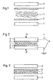
- FIGS. 1 to 3 The implementation of the method according to the invention show the FIGS. 1 to 3 , It is schematically in Fig. 1 a first, in Fig. 2 a second and in Fig. 3 a third process step shown.
- the metal fibers 1 are treated as uncompacted fiber material on both opposite flat sides, each with a wire cloth 2.
- a planar electrode 3 is provided, each of which is moved in the direction of the metal fibers 1, thus bringing together and pressing the wire mesh 2 and the metal fibers 1 in the manner of a pair of pliers.
- This process step is shown schematically in FIG Fig. 2 ,
- the electrodes 3 are hydraulically driven together with a predefined force F, for example, until a defined surface load, i. a defined contact pressure on the metal fibers 1 and the wire mesh 2 is applied. Simultaneously with the compression of the metal fibers 1 and the wire cloth 2 4 current is introduced into the electrodes 3 via the power connector.
- the current is introduced according to the invention by means not shown in this figure capacitors, with a short and strong current pulse of up to 200,000 A is passed through the wire cloth 2 and the metal fibers 1 by sudden discharge of the capacitors.
- electrical resistances are formed between the individual metal fibers, which causes the material is locally heated at these locations and selectively welded to the nearest fiber. In order to prevent oxidation during this welding process, the entire process is carried out under a protective gas atmosphere.
- Fig. 3 shows the finished metal fiber composite, which is sandwiched and has as cover layers two wire mesh, between which the compressed and welded together metal fibers 1 are arranged.
Landscapes
- Engineering & Computer Science (AREA)
- Mechanical Engineering (AREA)
- General Engineering & Computer Science (AREA)
- Chemical & Material Sciences (AREA)
- Combustion & Propulsion (AREA)
- Physics & Mathematics (AREA)
- Manufacturing & Machinery (AREA)
- Acoustics & Sound (AREA)
- Multimedia (AREA)
- Powder Metallurgy (AREA)
- Soundproofing, Sound Blocking, And Sound Damping (AREA)
- Laminated Bodies (AREA)
- Chemical Or Physical Treatment Of Fibers (AREA)
- Nonwoven Fabrics (AREA)
- Chemically Coating (AREA)
Applications Claiming Priority (3)
| Application Number | Priority Date | Filing Date | Title |
|---|---|---|---|
| DE10250716A DE10250716C1 (de) | 2002-10-31 | 2002-10-31 | Verfahren zur Herstellung eines porösen, plattenförmigen Metallverbundes |
| DE10250716 | 2002-10-31 | ||
| PCT/EP2003/012045 WO2004039580A1 (de) | 2002-10-31 | 2003-10-30 | Verfahren zur herstellung eines porösen, plattenförmigen metallverbundes |
Publications (3)
| Publication Number | Publication Date |
|---|---|
| EP1558443A1 EP1558443A1 (de) | 2005-08-03 |
| EP1558443B1 EP1558443B1 (de) | 2007-05-30 |
| EP1558443B2 true EP1558443B2 (de) | 2015-03-04 |
Family
ID=29594648
Family Applications (1)
| Application Number | Title | Priority Date | Filing Date |
|---|---|---|---|
| EP03775256.5A Expired - Lifetime EP1558443B2 (de) | 2002-10-31 | 2003-10-30 | Verfahren zur herstellung eines porösen, plattenförmigen metallverbundes |
Country Status (9)
| Country | Link |
|---|---|
| US (1) | US20060014451A1 (enExample) |
| EP (1) | EP1558443B2 (enExample) |
| JP (1) | JP4903383B2 (enExample) |
| CN (1) | CN1708397A (enExample) |
| AT (1) | ATE363381T1 (enExample) |
| AU (1) | AU2003283320A1 (enExample) |
| DE (2) | DE10250716C1 (enExample) |
| ES (1) | ES2285210T3 (enExample) |
| WO (1) | WO2004039580A1 (enExample) |
Families Citing this family (13)
| Publication number | Priority date | Publication date | Assignee | Title |
|---|---|---|---|---|
| DE10357693B4 (de) * | 2003-12-10 | 2010-04-15 | Melicon Gmbh | Verfahren zur Herstellung metallischer Gewebelaminate |
| EP1602803A1 (de) * | 2004-06-03 | 2005-12-07 | ABB Turbo Systems AG | Vorrichtung zum Reduzieren von Schwingungen eines Verbrennungsmotor und Abgasturbolader umfassenden Systems |
| DE102005028031A1 (de) * | 2005-06-17 | 2006-12-21 | Emitec Gesellschaft Für Emissionstechnologie Mbh | Wabenkörper-Herstellung mit einem metallischen Vlies |
| DE102006001833A1 (de) * | 2006-01-13 | 2007-07-19 | Emitec Gesellschaft Für Emissionstechnologie Mbh | Diskontinuierliches Verschweißen von metallischen Fasern |
| DE102009003363B4 (de) * | 2009-01-20 | 2013-01-10 | Webasto Ag | Heizgerät-Faserverdampfer |
| RU2011138927A (ru) * | 2009-02-25 | 2013-04-10 | Басф Се | Способ изготовления гибких металлических контактов |
| DE102010012416A1 (de) * | 2010-03-23 | 2011-09-29 | Dbw Holding Gmbh | Bauteil und Formteil sowie Herstellungsverfahren hierfür |
| GB2495735A (en) * | 2011-10-18 | 2013-04-24 | Bae Systems Plc | Transducer for acoustic communications |
| EP2985096B1 (de) | 2014-08-14 | 2016-11-02 | Melicon GmbH | Gasdiffusionselektrode |
| CN109226959B (zh) * | 2018-10-26 | 2020-08-25 | 同济大学 | 一种纤维增强金属基复合板材及其预处理方法 |
| CN112610984B (zh) * | 2020-12-14 | 2022-11-11 | 上海航天化工应用研究所 | 一种适用于高温高压的燃气隔离装置 |
| CN113245684A (zh) * | 2021-05-28 | 2021-08-13 | 中国石油化工股份有限公司 | 金属微纤材料及其定型方法、制备方法和应用 |
| DE102022209312A1 (de) * | 2022-09-07 | 2024-03-07 | Siemens Energy Global GmbH & Co. KG | Verfahren zur Herstellung eines Verbunds von Streckgittern, Stapel von Streckgittern und Portalmaschine |
Citations (8)
| Publication number | Priority date | Publication date | Assignee | Title |
|---|---|---|---|---|
| US3437783A (en) † | 1966-07-26 | 1969-04-08 | Jerome H Lemelson | Matte structure and method of producing same |
| US3469297A (en) † | 1966-04-20 | 1969-09-30 | Brunswick Corp | Porous metal structure |
| US3505038A (en) † | 1964-08-24 | 1970-04-07 | Brunswick Corp | Metal fibril compacts |
| WO1993018342A1 (en) † | 1992-03-03 | 1993-09-16 | N.V. Bekaert S.A. | Porous metal fiber plate |
| WO1994014608A1 (en) † | 1992-12-18 | 1994-07-07 | N.V. Bekaert S.A. | Porous sintered laminate containing metal fibers |
| BE1007596A3 (nl) † | 1993-10-08 | 1995-08-16 | Bekaert Sa Nv | Poreuze metaalvezelplaat. |
| WO2000071284A1 (fr) † | 1999-05-21 | 2000-11-30 | Renault | Procede et dispositif de formage de pieces metalliques poreuses par frittage |
| US6410878B1 (en) † | 1999-04-16 | 2002-06-25 | Gaz De France (Gdf) Service National | Method for producing a flame support |
Family Cites Families (13)
| Publication number | Priority date | Publication date | Assignee | Title |
|---|---|---|---|---|
| US2604517A (en) * | 1947-04-23 | 1952-07-22 | Everett D Mccurdy | Electrode and terminal assembly for electrolytic devices and methods of making same |
| US3384958A (en) * | 1965-06-30 | 1968-05-28 | Ibm | Method of brazing |
| FR2585603B1 (fr) * | 1985-08-05 | 1990-09-14 | Asturienne France | Panneau sandwich, son procede de fabrication et appareil pour la mise en oeuvre de ce procede |
| JPS63266018A (ja) * | 1987-04-22 | 1988-11-02 | Nippon Seisen Kk | 金属繊維材料の為の熱処理炉 |
| DE3935120C2 (de) * | 1989-10-21 | 1997-03-13 | Reiner Prof Dr Ing Kopp | Verfahren zur Herstellung von Metallverbundplatten |
| JPH08284279A (ja) * | 1995-04-13 | 1996-10-29 | Toyo Electric Mfg Co Ltd | アルミニウム繊維の吸音材製造方法 |
| JPH09143510A (ja) * | 1995-11-14 | 1997-06-03 | Kataoka Tokushu Kogyo Kk | 電池電極基板用金属繊維多孔体、電池電極板およびその製造方法 |
| FR2767088B1 (fr) * | 1997-08-06 | 1999-09-03 | Usinor | Tole de structure multicouche dite tole sandwich |
| DE19924675A1 (de) * | 1999-05-29 | 2000-11-30 | Gkn Sinter Metals Filters Gmbh | Sintermetallurgisches Verfahren zur Herstellung eines Filterkörpers aus schmelzextrahierten Metallfasern |
| DE10045342C1 (de) * | 2000-09-14 | 2001-11-22 | Drafas Gmbh | Einrichtung zum Behandeln von Abgasen aus technischen Verbrennungsprozessen |
| US6465110B1 (en) * | 2000-10-10 | 2002-10-15 | Material Sciences Corporation | Metal felt laminate structures |
| DE20119367U1 (de) * | 2001-11-29 | 2002-04-11 | Cambridge University Technical Services Ltd., Cambridge | Sandwich-Verbundmaterial |
| US20040247927A1 (en) * | 2003-06-06 | 2004-12-09 | Kurz Douglas L. | Method of producing seamless, multi-layer, bonded, metallic, laminate strips or coils of arbitrarily long length |
-
2002
- 2002-10-31 DE DE10250716A patent/DE10250716C1/de not_active Expired - Fee Related
-
2003
- 2003-10-30 AT AT03775256T patent/ATE363381T1/de not_active IP Right Cessation
- 2003-10-30 ES ES03775256T patent/ES2285210T3/es not_active Expired - Lifetime
- 2003-10-30 EP EP03775256.5A patent/EP1558443B2/de not_active Expired - Lifetime
- 2003-10-30 JP JP2004547612A patent/JP4903383B2/ja not_active Expired - Fee Related
- 2003-10-30 AU AU2003283320A patent/AU2003283320A1/en not_active Abandoned
- 2003-10-30 CN CNA200380102197XA patent/CN1708397A/zh active Pending
- 2003-10-30 US US10/533,438 patent/US20060014451A1/en not_active Abandoned
- 2003-10-30 WO PCT/EP2003/012045 patent/WO2004039580A1/de not_active Ceased
- 2003-10-30 DE DE50307390T patent/DE50307390D1/de not_active Expired - Lifetime
Patent Citations (10)
| Publication number | Priority date | Publication date | Assignee | Title |
|---|---|---|---|---|
| US3505038A (en) † | 1964-08-24 | 1970-04-07 | Brunswick Corp | Metal fibril compacts |
| US3469297A (en) † | 1966-04-20 | 1969-09-30 | Brunswick Corp | Porous metal structure |
| US3437783A (en) † | 1966-07-26 | 1969-04-08 | Jerome H Lemelson | Matte structure and method of producing same |
| WO1993018342A1 (en) † | 1992-03-03 | 1993-09-16 | N.V. Bekaert S.A. | Porous metal fiber plate |
| WO1994014608A1 (en) † | 1992-12-18 | 1994-07-07 | N.V. Bekaert S.A. | Porous sintered laminate containing metal fibers |
| US5679441A (en) † | 1992-12-18 | 1997-10-21 | N.V. Bekaert S.A. | Process for continuously manufacturing a porous laminate |
| BE1007596A3 (nl) † | 1993-10-08 | 1995-08-16 | Bekaert Sa Nv | Poreuze metaalvezelplaat. |
| US6410878B1 (en) † | 1999-04-16 | 2002-06-25 | Gaz De France (Gdf) Service National | Method for producing a flame support |
| WO2000071284A1 (fr) † | 1999-05-21 | 2000-11-30 | Renault | Procede et dispositif de formage de pieces metalliques poreuses par frittage |
| US6674042B1 (en) † | 1999-05-21 | 2004-01-06 | Renault Sas | Method and device for forming porous metal parts by sintering |
Non-Patent Citations (1)
| Title |
|---|
| "Capacitor Discharge Welding Technical Data", CD FUSION SOLUTIONS, 18 May 2001 (2001-05-18), pages 2 - 13 † |
Also Published As
| Publication number | Publication date |
|---|---|
| DE50307390D1 (de) | 2007-07-12 |
| US20060014451A1 (en) | 2006-01-19 |
| AU2003283320A1 (en) | 2004-05-25 |
| CN1708397A (zh) | 2005-12-14 |
| ES2285210T3 (es) | 2007-11-16 |
| EP1558443B1 (de) | 2007-05-30 |
| ATE363381T1 (de) | 2007-06-15 |
| JP4903383B2 (ja) | 2012-03-28 |
| DE10250716C1 (de) | 2003-12-24 |
| EP1558443A1 (de) | 2005-08-03 |
| WO2004039580A1 (de) | 2004-05-13 |
| JP2006504878A (ja) | 2006-02-09 |
Similar Documents
| Publication | Publication Date | Title |
|---|---|---|
| EP1558443B2 (de) | Verfahren zur herstellung eines porösen, plattenförmigen metallverbundes | |
| EP0659108B1 (de) | Walzenpressen, insbesondere zum zerkleinern von stark abrasiven stoffen | |
| DE69303932T2 (de) | Poröses gesintertes Laminat mit Metallfasern | |
| EP1439895B1 (de) | Hitzebeständige filterlage, filterkörper und verfahren zu seiner herstellung | |
| DE69808003T2 (de) | Mehrschichtiges Blech, genannt Sandwich-Blech | |
| DE3314264A1 (de) | Verfahren zur herstellung von stahl-verbundrohren | |
| DE1063233B (de) | Elektrode fuer alkalische Sammler, deren Traeger der aktiven Masse aus miteinander versinterten Metallfaeden od. dgl. besteht, sowie Verfahren und Vorrichtung zu deren Herstellung | |
| DE3935120C2 (de) | Verfahren zur Herstellung von Metallverbundplatten | |
| EP1954485B1 (de) | Gewebelaminat als auskleidung zur schallabsorption von ein- und auslasschalldämpfern und herstellungsverfahren einer akustischen isolationseinheit | |
| EP1222049B1 (de) | Verfahren und vorrichtung zur stirnseitigen fügetechnischen verbindung einer trägermatrix eines wabenkörpers | |
| EP0680549B1 (de) | Elektrisch isolierende stützstruktur mit möglichkeit zur metallischen anbindung, verfahren zur ihrer herstellung und deren anwendung | |
| EP2401789A1 (de) | Verfahren zur herstellung flexibler metallkontakte | |
| DE102016208881A1 (de) | Abschirmbauteil | |
| DE102009018762A1 (de) | Verfahren zum Herstellen eines metallischen Verbundwerkstoffs mit Kohlenstoffnanoröhren sowie eines endformnahen Bauteils aus diesem Verbundwerkstoff | |
| DE102013214389A1 (de) | Gehäusecontainment | |
| DE69929414T2 (de) | Verfahren zur Herstellung dünner, leichter und starrer Metallwerstücken | |
| DE102008052604B4 (de) | Faserverstärkter Verbundwerkstoff sowie Verfahren zur Herstellung desselben | |
| DE3035722C2 (de) | Verfahren zur Herstellung hochtemperaturbeständiger Schalldämmplatten in Sandwichbauweise | |
| DE2223083A1 (de) | Elektrodenplatte fuer Batteriezellen und Verfahren zur Herstellung | |
| DE102005055955B3 (de) | Solarempfänger | |
| DE10219853A1 (de) | Verfestigtes Drahtgestrick | |
| DE4322431A1 (de) | Kühlstruktur und Verfahren zu ihrer Herstellung | |
| EP3141863A1 (de) | Bauteil für ballistische schutzanwendungen und verfahren zu dessen herstellung | |
| WO1996034398A1 (de) | Glimmerhaltiger werkstoff | |
| EP1046492A2 (de) | Verbundwerkstoff, insbesondere in Form eines Bleches, und Verfahren zu seiner Herstellung |
Legal Events
| Date | Code | Title | Description |
|---|---|---|---|
| PUAI | Public reference made under article 153(3) epc to a published international application that has entered the european phase |
Free format text: ORIGINAL CODE: 0009012 |
|
| 17P | Request for examination filed |
Effective date: 20050422 |
|
| AK | Designated contracting states |
Kind code of ref document: A1 Designated state(s): AT BE BG CH CY CZ DE DK EE ES FI FR GB GR HU IE IT LI LU MC NL PT RO SE SI SK TR |
|
| AX | Request for extension of the european patent |
Extension state: AL LT LV MK |
|
| DAX | Request for extension of the european patent (deleted) | ||
| GRAP | Despatch of communication of intention to grant a patent |
Free format text: ORIGINAL CODE: EPIDOSNIGR1 |
|
| GRAS | Grant fee paid |
Free format text: ORIGINAL CODE: EPIDOSNIGR3 |
|
| GRAA | (expected) grant |
Free format text: ORIGINAL CODE: 0009210 |
|
| AK | Designated contracting states |
Kind code of ref document: B1 Designated state(s): AT BE BG CH CY CZ DE DK EE ES FI FR GB GR HU IE IT LI LU MC NL PT RO SE SI SK TR |
|
| PG25 | Lapsed in a contracting state [announced via postgrant information from national office to epo] |
Ref country code: FI Free format text: LAPSE BECAUSE OF FAILURE TO SUBMIT A TRANSLATION OF THE DESCRIPTION OR TO PAY THE FEE WITHIN THE PRESCRIBED TIME-LIMIT Effective date: 20070530 |
|
| REG | Reference to a national code |
Ref country code: GB Ref legal event code: FG4D Free format text: NOT ENGLISH |
|
| REG | Reference to a national code |
Ref country code: CH Ref legal event code: EP |
|
| REG | Reference to a national code |
Ref country code: IE Ref legal event code: FG4D Free format text: LANGUAGE OF EP DOCUMENT: GERMAN |
|
| REF | Corresponds to: |
Ref document number: 50307390 Country of ref document: DE Date of ref document: 20070712 Kind code of ref document: P |
|
| GBT | Gb: translation of ep patent filed (gb section 77(6)(a)/1977) |
Effective date: 20070702 |
|
| PG25 | Lapsed in a contracting state [announced via postgrant information from national office to epo] |
Ref country code: SE Free format text: LAPSE BECAUSE OF FAILURE TO SUBMIT A TRANSLATION OF THE DESCRIPTION OR TO PAY THE FEE WITHIN THE PRESCRIBED TIME-LIMIT Effective date: 20070830 |
|
| ET | Fr: translation filed | ||
| REG | Reference to a national code |
Ref country code: ES Ref legal event code: FG2A Ref document number: 2285210 Country of ref document: ES Kind code of ref document: T3 |
|
| NLV1 | Nl: lapsed or annulled due to failure to fulfill the requirements of art. 29p and 29m of the patents act | ||
| REG | Reference to a national code |
Ref country code: IE Ref legal event code: FD4D |
|
| PG25 | Lapsed in a contracting state [announced via postgrant information from national office to epo] |
Ref country code: BG Free format text: LAPSE BECAUSE OF FAILURE TO SUBMIT A TRANSLATION OF THE DESCRIPTION OR TO PAY THE FEE WITHIN THE PRESCRIBED TIME-LIMIT Effective date: 20070830 Ref country code: DK Free format text: LAPSE BECAUSE OF FAILURE TO SUBMIT A TRANSLATION OF THE DESCRIPTION OR TO PAY THE FEE WITHIN THE PRESCRIBED TIME-LIMIT Effective date: 20070530 Ref country code: CZ Free format text: LAPSE BECAUSE OF FAILURE TO SUBMIT A TRANSLATION OF THE DESCRIPTION OR TO PAY THE FEE WITHIN THE PRESCRIBED TIME-LIMIT Effective date: 20070530 Ref country code: NL Free format text: LAPSE BECAUSE OF FAILURE TO SUBMIT A TRANSLATION OF THE DESCRIPTION OR TO PAY THE FEE WITHIN THE PRESCRIBED TIME-LIMIT Effective date: 20070530 Ref country code: IE Free format text: LAPSE BECAUSE OF FAILURE TO SUBMIT A TRANSLATION OF THE DESCRIPTION OR TO PAY THE FEE WITHIN THE PRESCRIBED TIME-LIMIT Effective date: 20070530 Ref country code: SI Free format text: LAPSE BECAUSE OF FAILURE TO SUBMIT A TRANSLATION OF THE DESCRIPTION OR TO PAY THE FEE WITHIN THE PRESCRIBED TIME-LIMIT Effective date: 20070530 Ref country code: PT Free format text: LAPSE BECAUSE OF FAILURE TO SUBMIT A TRANSLATION OF THE DESCRIPTION OR TO PAY THE FEE WITHIN THE PRESCRIBED TIME-LIMIT Effective date: 20071030 |
|
| PLBI | Opposition filed |
Free format text: ORIGINAL CODE: 0009260 |
|
| PG25 | Lapsed in a contracting state [announced via postgrant information from national office to epo] |
Ref country code: SK Free format text: LAPSE BECAUSE OF FAILURE TO SUBMIT A TRANSLATION OF THE DESCRIPTION OR TO PAY THE FEE WITHIN THE PRESCRIBED TIME-LIMIT Effective date: 20070530 |
|
| 26 | Opposition filed |
Opponent name: NV BEKAERT SA Effective date: 20080219 |
|
| PLAX | Notice of opposition and request to file observation + time limit sent |
Free format text: ORIGINAL CODE: EPIDOSNOBS2 |
|
| BERE | Be: lapsed |
Owner name: MELICON G.M.B.H. Effective date: 20071031 |
|
| PG25 | Lapsed in a contracting state [announced via postgrant information from national office to epo] |
Ref country code: GR Free format text: LAPSE BECAUSE OF FAILURE TO SUBMIT A TRANSLATION OF THE DESCRIPTION OR TO PAY THE FEE WITHIN THE PRESCRIBED TIME-LIMIT Effective date: 20070831 |
|
| PG25 | Lapsed in a contracting state [announced via postgrant information from national office to epo] |
Ref country code: MC Free format text: LAPSE BECAUSE OF NON-PAYMENT OF DUE FEES Effective date: 20071031 Ref country code: RO Free format text: LAPSE BECAUSE OF FAILURE TO SUBMIT A TRANSLATION OF THE DESCRIPTION OR TO PAY THE FEE WITHIN THE PRESCRIBED TIME-LIMIT Effective date: 20070530 |
|
| REG | Reference to a national code |
Ref country code: CH Ref legal event code: PL |
|
| PG25 | Lapsed in a contracting state [announced via postgrant information from national office to epo] |
Ref country code: LI Free format text: LAPSE BECAUSE OF NON-PAYMENT OF DUE FEES Effective date: 20071031 Ref country code: CH Free format text: LAPSE BECAUSE OF NON-PAYMENT OF DUE FEES Effective date: 20071031 |
|
| PLAF | Information modified related to communication of a notice of opposition and request to file observations + time limit |
Free format text: ORIGINAL CODE: EPIDOSCOBS2 |
|
| PG25 | Lapsed in a contracting state [announced via postgrant information from national office to epo] |
Ref country code: BE Free format text: LAPSE BECAUSE OF NON-PAYMENT OF DUE FEES Effective date: 20071031 |
|
| PLBB | Reply of patent proprietor to notice(s) of opposition received |
Free format text: ORIGINAL CODE: EPIDOSNOBS3 |
|
| PG25 | Lapsed in a contracting state [announced via postgrant information from national office to epo] |
Ref country code: EE Free format text: LAPSE BECAUSE OF FAILURE TO SUBMIT A TRANSLATION OF THE DESCRIPTION OR TO PAY THE FEE WITHIN THE PRESCRIBED TIME-LIMIT Effective date: 20070530 |
|
| PG25 | Lapsed in a contracting state [announced via postgrant information from national office to epo] |
Ref country code: AT Free format text: LAPSE BECAUSE OF NON-PAYMENT OF DUE FEES Effective date: 20071030 |
|
| PLAY | Examination report in opposition despatched + time limit |
Free format text: ORIGINAL CODE: EPIDOSNORE2 |
|
| PLAH | Information related to despatch of examination report in opposition + time limit modified |
Free format text: ORIGINAL CODE: EPIDOSCORE2 |
|
| PG25 | Lapsed in a contracting state [announced via postgrant information from national office to epo] |
Ref country code: CY Free format text: LAPSE BECAUSE OF FAILURE TO SUBMIT A TRANSLATION OF THE DESCRIPTION OR TO PAY THE FEE WITHIN THE PRESCRIBED TIME-LIMIT Effective date: 20070530 |
|
| PG25 | Lapsed in a contracting state [announced via postgrant information from national office to epo] |
Ref country code: LU Free format text: LAPSE BECAUSE OF NON-PAYMENT OF DUE FEES Effective date: 20071030 |
|
| PG25 | Lapsed in a contracting state [announced via postgrant information from national office to epo] |
Ref country code: HU Free format text: LAPSE BECAUSE OF FAILURE TO SUBMIT A TRANSLATION OF THE DESCRIPTION OR TO PAY THE FEE WITHIN THE PRESCRIBED TIME-LIMIT Effective date: 20071201 Ref country code: TR Free format text: LAPSE BECAUSE OF FAILURE TO SUBMIT A TRANSLATION OF THE DESCRIPTION OR TO PAY THE FEE WITHIN THE PRESCRIBED TIME-LIMIT Effective date: 20070530 |
|
| PLBC | Reply to examination report in opposition received |
Free format text: ORIGINAL CODE: EPIDOSNORE3 |
|
| APBM | Appeal reference recorded |
Free format text: ORIGINAL CODE: EPIDOSNREFNO |
|
| APBP | Date of receipt of notice of appeal recorded |
Free format text: ORIGINAL CODE: EPIDOSNNOA2O |
|
| APAH | Appeal reference modified |
Free format text: ORIGINAL CODE: EPIDOSCREFNO |
|
| APBQ | Date of receipt of statement of grounds of appeal recorded |
Free format text: ORIGINAL CODE: EPIDOSNNOA3O |
|
| PGFP | Annual fee paid to national office [announced via postgrant information from national office to epo] |
Ref country code: FR Payment date: 20121031 Year of fee payment: 10 |
|
| PGFP | Annual fee paid to national office [announced via postgrant information from national office to epo] |
Ref country code: IT Payment date: 20121025 Year of fee payment: 10 Ref country code: ES Payment date: 20121026 Year of fee payment: 10 Ref country code: GB Payment date: 20121019 Year of fee payment: 10 |
|
| GBPC | Gb: european patent ceased through non-payment of renewal fee |
Effective date: 20131030 |
|
| PG25 | Lapsed in a contracting state [announced via postgrant information from national office to epo] |
Ref country code: GB Free format text: LAPSE BECAUSE OF NON-PAYMENT OF DUE FEES Effective date: 20131030 |
|
| REG | Reference to a national code |
Ref country code: FR Ref legal event code: ST Effective date: 20140630 |
|
| PG25 | Lapsed in a contracting state [announced via postgrant information from national office to epo] |
Ref country code: FR Free format text: LAPSE BECAUSE OF NON-PAYMENT OF DUE FEES Effective date: 20131031 Ref country code: IT Free format text: LAPSE BECAUSE OF NON-PAYMENT OF DUE FEES Effective date: 20131030 |
|
| APBU | Appeal procedure closed |
Free format text: ORIGINAL CODE: EPIDOSNNOA9O |
|
| REG | Reference to a national code |
Ref country code: ES Ref legal event code: FD2A Effective date: 20141107 |
|
| PG25 | Lapsed in a contracting state [announced via postgrant information from national office to epo] |
Ref country code: ES Free format text: LAPSE BECAUSE OF NON-PAYMENT OF DUE FEES Effective date: 20131031 |
|
| PUAH | Patent maintained in amended form |
Free format text: ORIGINAL CODE: 0009272 |
|
| STAA | Information on the status of an ep patent application or granted ep patent |
Free format text: STATUS: PATENT MAINTAINED AS AMENDED |
|
| 27A | Patent maintained in amended form |
Effective date: 20150304 |
|
| AK | Designated contracting states |
Kind code of ref document: B2 Designated state(s): AT BE BG CH CY CZ DE DK EE ES FI FR GB GR HU IE IT LI LU MC NL PT RO SE SI SK TR |
|
| REG | Reference to a national code |
Ref country code: DE Ref legal event code: R102 Ref document number: 50307390 Country of ref document: DE |
|
| REG | Reference to a national code |
Ref country code: DE Ref legal event code: R102 Ref document number: 50307390 Country of ref document: DE Effective date: 20150304 |
|
| REG | Reference to a national code |
Ref country code: DE Ref legal event code: R082 Ref document number: 50307390 Country of ref document: DE Representative=s name: BRINKMANN & PARTNER PATENTANWAELTE PARTNERSCHA, DE Ref country code: DE Ref legal event code: R082 Ref document number: 50307390 Country of ref document: DE Representative=s name: RAUSCH WANISCHECK-BERGMANN BRINKMANN PARTNERSC, DE |
|
| PGFP | Annual fee paid to national office [announced via postgrant information from national office to epo] |
Ref country code: DE Payment date: 20221223 Year of fee payment: 20 |
|
| P01 | Opt-out of the competence of the unified patent court (upc) registered |
Effective date: 20230517 |
|
| REG | Reference to a national code |
Ref country code: DE Ref legal event code: R071 Ref document number: 50307390 Country of ref document: DE |