EP1558415B1 - Procede et appareil de pressage de trou transversal afin de produire des inserts de decoupe - Google Patents
Procede et appareil de pressage de trou transversal afin de produire des inserts de decoupe Download PDFInfo
- Publication number
- EP1558415B1 EP1558415B1 EP03776529A EP03776529A EP1558415B1 EP 1558415 B1 EP1558415 B1 EP 1558415B1 EP 03776529 A EP03776529 A EP 03776529A EP 03776529 A EP03776529 A EP 03776529A EP 1558415 B1 EP1558415 B1 EP 1558415B1
- Authority
- EP
- European Patent Office
- Prior art keywords
- cavity
- core rod
- green part
- ram
- die
- Prior art date
- Legal status (The legal status is an assumption and is not a legal conclusion. Google has not performed a legal analysis and makes no representation as to the accuracy of the status listed.)
- Revoked
Links
Images

Classifications
-
- B—PERFORMING OPERATIONS; TRANSPORTING
- B22—CASTING; POWDER METALLURGY
- B22F—WORKING METALLIC POWDER; MANUFACTURE OF ARTICLES FROM METALLIC POWDER; MAKING METALLIC POWDER; APPARATUS OR DEVICES SPECIALLY ADAPTED FOR METALLIC POWDER
- B22F3/00—Manufacture of workpieces or articles from metallic powder characterised by the manner of compacting or sintering; Apparatus specially adapted therefor ; Presses and furnaces
- B22F3/02—Compacting only
- B22F3/03—Press-moulding apparatus therefor
-
- B—PERFORMING OPERATIONS; TRANSPORTING
- B22—CASTING; POWDER METALLURGY
- B22F—WORKING METALLIC POWDER; MANUFACTURE OF ARTICLES FROM METALLIC POWDER; MAKING METALLIC POWDER; APPARATUS OR DEVICES SPECIALLY ADAPTED FOR METALLIC POWDER
- B22F5/00—Manufacture of workpieces or articles from metallic powder characterised by the special shape of the product
- B22F5/10—Manufacture of workpieces or articles from metallic powder characterised by the special shape of the product of articles with cavities or holes, not otherwise provided for in the preceding subgroups
-
- B—PERFORMING OPERATIONS; TRANSPORTING
- B22—CASTING; POWDER METALLURGY
- B22F—WORKING METALLIC POWDER; MANUFACTURE OF ARTICLES FROM METALLIC POWDER; MAKING METALLIC POWDER; APPARATUS OR DEVICES SPECIALLY ADAPTED FOR METALLIC POWDER
- B22F5/00—Manufacture of workpieces or articles from metallic powder characterised by the special shape of the product
- B22F2005/001—Cutting tools, earth boring or grinding tool other than table ware
-
- B—PERFORMING OPERATIONS; TRANSPORTING
- B22—CASTING; POWDER METALLURGY
- B22F—WORKING METALLIC POWDER; MANUFACTURE OF ARTICLES FROM METALLIC POWDER; MAKING METALLIC POWDER; APPARATUS OR DEVICES SPECIALLY ADAPTED FOR METALLIC POWDER
- B22F2999/00—Aspects linked to processes or compositions used in powder metallurgy
Definitions
- the invention is directed to the field of pressing of powders to make inserts.
- Powder metallurgy has become a viable alternative to traditional casting and machining techniques.
- one or more powder metals and/or ceramics, with or without a fugitive binder are added to a mold and then compacted under very high pressures, typically between about 20-80 tons per 6,45 cm 2 .
- the compacted part is ejected from the mold as a "green" part.
- the green part is then sintered in a furnace operating at temperatures of typically 1100°-1950°C.
- the sintering temperature depends upon the composition of the powder mixture. For example, cemented carbide and cermets are typically sintered at 1350°-1450°C while ceramics are typically sintered at 1500°-1950°C.
- the sintering process effectively welds together all of the individual powder grains into a solid mass of considerable mechanical strength with little, if any, porosity.
- the powder metallurgy process can be generally used to make parts from any type of powder and sintering temperatures are primarily determined by the temperature of fusion of each powder type.
- Powder metallurgy parts have several significant advantages over traditional cast or machine parts. Powder metallurgy parts can be molded with very intricate features that eliminate much of the grinding that is required with conventional fabrication. Powder metallurgy parts can be molded to tolerances within about four or five thousandths of an inch, a level of precision acceptable for many machined surfaces. Surfaces which require tighter tolerances can be quickly and easily ground since only a small amount of surface material need be removed. Surfaces of powder metallurgy parts are very smooth and offer an excellent finish which is suitable for bearing surfaces.
- the powder metallurgy process is also very efficient compared with other processes. Powder metallurgy processes are capable of typically producing between 200-2,000 pieces per hour, depending on the size and of the degree of complexity.
- the molds are typically capable of thousands of service hours before wearing out and requiring replacement. Since almost all of the powder which enters the mold becomes part of the finished product, the powder metallurgy process is about 97% material efficient.
- sintering it is only necessary to heat the green part to a temperature which permits fusion of the powder granules. This temperature is typically much lower than the melting points of the powders, and so sintering is considerably more energy efficient than a comparable casting process.
- Powder metallurgy parts are molded under high pressures which are obtained through large opposing forces that are generated by the molding equipment. These forces are applied by mold elements which move back and forth in opposing vertical directions along a pressing axis.
- the powder metallurgy parts produced thereby have previously necessarily had a "vertical" profile. Since mold elements move back and forth in opposing vertical directions, powder metallurgy parts formed with transverse features, i.e., holes, grooves, undercuts, cross-cuts or threads, would inhibit mold release and therefore these features would not be pressed into the green part. Such profile features then required a secondary machining step which added greatly to the cost of the part and creates an economic disincentive to fabricate parts using powder metallurgy.
- JP-A 10-118796 is directed to a method of pressing a raw material powder in a die with a cavity therein, with the die having a male side pin and a female-side pin that come and go freely in the cavity and project together to form a horizontal hole in the compressed green part.
- the male-side pin and the female-side pin are provided with tapered parts to chamfer the horizontal hole.
- the male-side pin and the female side-pin are introduced into the cavity which is then loaded with the raw material powder.
- the powder is then compressed using upper and lower punches. Thereafter, the male-side pin and female-side pin are retracted from the cavity, and the green part is ejected.
- the male-side pin and the female-side pin may have a square cross-section.
- a method and apparatus are desired capable of effectively imparting a through hole with or without a counterbore through a cutting insert using powder pressing techniques.
- the invention is directed to a method of fabricating an article having an opening using a press with a uni-axial press motion, according to claim 1.
- the invention is further directed to a uni-axial press for forming a green part from metallurgical powder, according to claim 17.
- the invention is directed to an article comprised of compacted metallurgical powder according to claim 24.
- Figure 1 is an isometric view of a green part fabricated in accordance with the method and apparatus of the subject invention and sintered to form a cutting insert;
- Figure 2 is a front view of the cutting insert shown in Figure 1 ;
- Figure 3 is a sectional view along lines "III-III" in Figure 1 ;
- Figure 4 is an isometric view of an unsintered green part fabricated in accordance with the method and apparatus of the subject invention
- Figure 5 is a front view of the unsintered green form shown in Figure 4 ;
- Figure 6 is a schematic of the parts of a die press in accordance with the subject invention.
- Figures 7A-7F illustrate the sequence of die part positions to form a green part in accordance with the subject invention
- Figure 8 is a view of the die along lines "VIII-VIII" in Figure 7A ;
- Figure 9 is a cross-sectional view of the die illustrating the profile of the core rods in accordance with one embodiment of the subject invention.
- Figure 10 is a cross-sectional view along the lines "X-X" in Figure 9 ;
- Figure 11 is a cross-sectional view along lines "XI-XI" in Figure 9 ;
- Figure 12 is a cross-sectional view of the die illustrating the profile of the core rods in accordance with an alternate embodiment of the invention.
- Figure 13 is an enlarged view of the encircled area in Figure 12 with the core rod parts in the closed position.
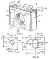
- Figure 1 is an isometric view and Figure 2 is a front view of an article which, in this instance, is a cutting insert 10 after a sintering operation.
- the cutting insert 10 has a body 11 with a first lateral wall 12, an opposing second lateral wall 14 and an adjacent first end wall 18 and opposing second end wall 22 therebetween.
- the body has a top 16 and a bottom 20. At the intersection of the walls and the top is a cutting edge 23.
- the distance D1 between the first lateral wall 12 and the second lateral wall 14 defines the article depth.
- a central opening 25 with a peripheral wall 27 extends about a central axis 30 through the depth of the insert 10.
- a parting line 35 extends about the peripheral wall 27.
- the parting line 35 may extend about the peripheral wall 27 in a plane 40 perpendicular to the central axis 30. It should be appreciated that while the opening is referred to as a central opening, it is entirely possible that the opening is not centrally located but is offset from the center in one or both the vertical and horizontal direction.
- the cutting insert 10 has a major axis 70 parallel to the pressing axis (not shown) of the press with a major width W1 thereacross and has a minor axis 80 perpendicular to the pressing axis with a minor width W2 thereacross.
- the cutting insert 10 may have chip control features 50.
- the chip control features 50 may be comprised of a rake face 52 extending downwardly and away from the cutting edge 23 and a plateau wall 54 extending upwardly to a plateau 56 and away from the rake face 52 thereby defining an interrupted path that will promote chip control.
- These chip control features are generally recessed in a planar region that is perpendicular to the pressing axis of the press to be described. While the discussion has been focused on features upon the top 16 of the green part 110, it should be appreciated that similar or identical features may also exist on the bottom 18 of the green part 110.
- the sintered cutting insert 10 begins with a green part comprised of compressed metallurgical powder which, upon heating to a sintering temperature, densifies and shrinks to the size and shape of the cutting insert 10 with or without grind stock left on it.
- the metallurgical powder may be tungsten carbide powder, cobalt powder and a solid solution carbide forming powder with a fugitive binder mixed in.
- the shrinkage of the green part to the shape of the cutting insert is not uniform. This becomes particularly significant when an opening is present within the insert having an axis in a direction perpendicular to the travel direction of the press rams.
- the percentage of shrinkage of the opening during sintering is greater in the direction in which greater compression has occurred.
- the shrinkage factor of the opening and the counterbore after sintering is approximately 1.18 in a horizontal direction, which is perpendicular to the pressing axis and 1.22 in a vertical direction, which is parallel to the pressing axis. For this reason, when a circular hole is desired in the cutting insert, the hole in the unsintered green part must be non-circular. It should be noted that under different press pressures, these shrinkage factors may change.
- FIG. 1 an isometric and a front view of a green part 110 are illustrated prior to sintering to a cutting insert 10 ( Fig. 1 ).
- the reference numbers used in association with the green part 110 will be the same as those used for the cutting insert 10, but incremented by 100.
- the green part 110 has a body 111 with a first lateral wall 112, an opposing second lateral wall 114 and an adjacent first end wall 118 and opposing second end wall 122 therebetween.
- the body has a top 116 and a bottom 120.
- At the intersection of the walls 112, 114, 118, 122 and the top is a cutting edge 123.
- the distance D2 between the first lateral wall 112 and the second lateral wall 114 defines the green part 110 depth.
- a central opening 125 with a peripheral wall 127 extends about a central axis 130 through the depth D2 of the green part 110.
- a parting line 135 extends about the peripheral wall 127.
- the parting line 135 may extend about the peripheral wall 127 in a plane 140 perpendicular to the central axis 130.
- the green part 110 has a major axis 170 parallel to the pressing axis 215 with a major width W3 thereacross and has a minor axis 180 perpendicular to the pressing axis 215 with a minor width W4 thereacross.
- the entire green part 110 will shrink and, therefore, the green part 110 must be specifically shaped to account for such shrinkage.
- the central opening 125 in particular, must be shaped such that, after sintering the opening 125 conforms to a desired final shape. As illustrated in Figure 1 , one such final shape of the central opening 25 is circular.
- the central opening 125 of the green part 110 it is necessary for the central opening 125 of the green part 110 to have a non-circular shape.
- that non-circular shape of the central opening 125 is oval and, in the shape of an oval racetrack having a first end 145 and a second end 147 with semi-circular shapes, which connect with a first side 149 and a second side 151 having generally straight profiles.
- Such an arrangement has been shown to produce, after sintering, a central opening 125 having a circular shape.
- the cutting insert 10 has a central opening 25 with a beveled counterbore 42.
- the beveled counterbore 42 conforms to the shape of the central opening 25 and, as a result, the counterbore 142 ( Figure 5 ) of the green part 110 should be formed to a shape similar to the oval shaped central opening 125.
- a cutting insert 10 having a central opening 25 in the shape of a circle which is formed by sintering a green part 110 having a central opening 125 in the shape of an oval.
- the opening 25 ( Figure 1 ) in the sintered cutting insert may not need to be circular or, as previously mentioned, may not need to be centrally located. Under those circumstances it should be appreciated that the green part will be formed accordingly.
- the press for producing such a green part, and the method of utilizing such a press, will now be described.
- FIG. 6 illustrates a cross-sectional sketch of a press 200 used to produce a green part in accordance with the subject invention.
- the press 200 has a die 205 with a cavity 210 extending therethrough along the pressing axis 215 with a top ram 220 and a bottom ram 225 independently movable within the cavity to define a compression region 230.
- a removable core rod 235 is insertable within a core bore 240 through the cavity 210 at the compression region 230 in a direction perpendicular to the pressing axis 215.
- the core rod 235 has its own longitudinal axis 245 transverse to the pressing axis 215.
- the core rod 235 is comprised of a shaft 250 having a non-circular cross-section (not shown in Figure 6 ) to impart a non-circular hole within the green part 110 ( Figure 5 ).
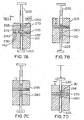
- Figures 7A-7F illustrate the steps in accordance with one embodiment of the subject invention for fabricating a green part 110.
- Figure 7A illustrates one step associated with the method of fabricating an article similar to the green part 110 shown in Figure 5 having a central opening 125.
- the article is fabricated using a press with a uni-axial press motion.
- the bottom ram 225 is positioned within the cavity 210 below the core bore 240, while the top ram 220 is positioned outside of the cavity 210.
- the removable core rod 235 is then positioned through the core bore 240 of the cavity 210.
- the cavity 210 is then filled with a predetermined amount of metallurgical powder 260 to form a powder bed 265 having opposite sides 270, 272.
- the metallurgical powder 260 is positioned about the core rod 235 to control the location of the central opening 25 ( Figure 1 ) after sintering.
- the position of the powder 260 is obtained through the elevation of the bottom ram 225 and/or the movement of the die 205 up or down. Generally the powder 260 will be positioned such that the opening 25 ( Fig.
- the opening 25 may be offset above, below or to the side of the geometric center by placement of the powder 260, or to the side of the geometric center, or by displacement of the core rod 235 to an offset position, by changing the die so the axis of the bore of the core rod is offset from the pressing axis.
- the die 205 is moved up and down relative to the top ram 220 and the bottom ram 225 to substantially uniformly distribute the metallurgical powder 260 within the cavity 210.
- the step of positioning the metallurgical powder 260 about the core rod 235 may be comprised of centering the metallurgical powder 260 about the core rod 235, as illustrated in Figure 7C .
- the top ram 220 is moved down and the bottom ram 225 is moved up against the metallurgical powder 260 to uniformly compress the metallurgical powder 260 about the core rod 235 to produce a green part 110 ( Figure 5 ).
- the top ram 220 and the bottom ram 225 may be moved equal distances or different distances to compress the green part 110, depending upon the circumstances.
- the green part 110 is formed to be sintered into a cutting insert 10.
- the process so far described utilizes a split core rod 235 comprised of a first segment 237 and a second segment 239 that meet within the cavity 210 of the die 205.
- top ram 220 and the bottom ram 225 are retracted, as illustrated in Figure 7E , a predetermined amount to allow decompression of the green part 110.
- the core rod 235 is retracted from within the cavity 210 such that the green part 110 is no longer held captive by the core rod 235 extending through the central opening 125.
- the green part 110 may be ejected from the die 205, as illustrated in Figure 7F .
- the top ram 220 is retracted completely from the cavity 210 and the bottom ram 225 is advanced until the green part 110 is ejected from the die 205.
- the top ram 220 and the bottom ram 225 may move simultaneously or they may move sequentially depending upon the desired operating conditions.
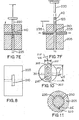
- Figure 8 illustrates a top view of the die 205 along arrows "VIII-VIII" in Figure 7A . It is apparent that the cavity 210 of the die 205 is rectangular, which is the shape of the green part 110 ( Fig.4 ) prior to decompression and sintering.
- the core rod 235 has been illustrated as a split type core rod 235 having two halves which meet within the cavity 210 to defme the opening within the green part 110.
- the removable core rod 235 it is entirely possible for the removable core rod 235 to be of the split pin type, wherein the core rod 235 has a matable first segment 237 and second segment 239 and the step of positioning the removable core rod 235 through the core bore 240 into the cavity 210 is comprised of moving the matable first segment 237 into the cavity 210 from one side of the die 205, and moving the matable second segment 239 into cavity 210 from the other side of the die 205 causing the two segments to meet within the cavity 210.
- the matable segments 237, 239 of the core rod 235 are moved into the cavity 210 such that they may contact each other along the pressing axis 215 of the cavity 210. As illustrated in Figure 12 and as will be discussed further, it is possible for the core rod segments 237, 239 to meet at a location other than along the pressing axis 215.
- the step of moving the top ram 220 down and the bottom ram 225 up to compress the metallurgical powder 260 is comprised of forming the central bore 125 ( Figure 5 ) of the green part 110 into a non-circular shape such that, when the green part 110 is sintered, the opening 125 will shrink a greater percentage along the pressing axis 215 ( Figures 5 and 6 ) than in a direction perpendicular to the pressing axis 215.
- the non-circular shape 125 is an oval racetrack and the resulting sintered shape is a circle however it should be understood that the non-circular shape may be any number of different configurations depending upon the desired sintered shape.
- the step of moving the top ram 220 down and the bottom ram 225 up to compress the metallurgical powder 260 may be further comprised of forming in at least one side 270 ( Fig. 7A ) of the powder bed 265 a counterbore 142 ( Fig.5 ) coaxial with the central opening 125. Additionally, the step of moving the top ram 220 down and the bottom ram 225 up to compress the metallurgical powder 260 may be comprised of imparting chip control features 150 to at least one edge 116 of the green part 110, as illustrated in Figure 4 .
- the chip control features 150 may be comprised of a rake face 152 extending downwardly and away from the cutting edge 123 and a plateau wall 154 extending upwardly to a plateau 156 and away from the rake face 152 thereby defining an interrupted path that will promote chip control.
- the top ram 220 and/or the bottom ram 225 must have a face with a profile complimentary to that of these chip control features or any other features 150 that may be imparted to the green part 110.
- the part is intended to be sintered, whereby a cutting insert is produced.
- an insert fabricated in accordance with the subject invention will have a parting line within the wall of the central opening extending through the insert.
- central feed body 20 to reduce wear caused by a material flow, is not solely affected by the spacing distance that bars are positioned adjacent each other.
- the effectiveness of central feed body 20, according to the present invention, to reduce wear by a material flow is a function in part of the spacing distance between hard material bars 50 on the central feed body, as well as the design, number, shape, configuration and location of the bars 50 on the central feed body 20 in relation to angles of incidence of a material flow against, over and around the central feed body 20, and the alloy composition of bars 50. Also, it should be appreciated that the hard material compositions used in the bars does not have to be used consistently throughout either the impeller shoe or central feed body.
- FIG. 9 illustrates a split core rod 235 having a first segment 237 and a second segment 239 movable within the core bore 240 along the core bore longitudinal axis 245.
- the core rod 235 within the region of the cavity 210 has a cross-sectional configuration identical to the cross-sectional configuration of the central opening 125 illustrated in Figure 5 .
- This cross-sectional area, shown in Figure 10 has a the shape of an oval and, is comprised of a first end 305 and a second end 307 having semi-circular shapes and connected by a first straight side 309 and second straight side 311 connecting therebetween.
- the core rod 235 has a major axis 295 parallel to the pressing axis 215 with a major width W5 thereacross and has a minor axis 297 perpendicular to the pressing axis 215 with a minor width W6 thereacross
- Figure 11 illustrates a cross sectional view of the core rod 235 shown in Figure 9 to show that the shaft 250 of the core rod 235 may have a key 315 which aligns with the channel 320 in the die 205 to properly orient the core rod 235 within the die 205.
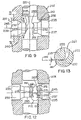
- first segment 237 and a second segment 239 each have complementary ends 251, 255 that meet to form a continuous core rod (not shown).
- End 251 of the first segment 237 has a curved indentation 252, while end 255 of the second segment 239 has a complementary curved projection 257 to mate with the indentation 252.
- the first segment 237 also has a peripheral planar ring 253 surrounding the indentation 252, while the second segment 239 has a complementary peripheral planar ring 259 surrounding the projection 257 such that the planar rings 253, 259 meet and contact one another.
- an end 251 of the core rod first segment 237 has a central cavity 262 surrounded by a wall 267 to define a cavity contour 271.
- End 255 of the core rod second segment 239 has a projection 280 in the shape of the cavity contour 271 but reduced such that the second segment 239 fits within the first segment 237.
- the end 251 of the first segment 237 may have a concave surface 275 to promote contact between the first segment 237 and the second segment 239.
- Figure 13 illustrates an enlarged section of the encircled area in Figure 12 highlighting the manner in which the end 251 of the first segment 237 mates with the end 255 of the second segment 239.
- the projection 280 of the core rod second segment 239 has exterior walls 285 about a central axis 245 and the walls 285 have a taper T between 1-20° relative to the core rod longitudinal axis 245 to promote mating with the cavity 262 of the first segment 237.
- the core rod 235 is comprised of two mating parts, it should be appreciated that it is entirely possible for the core rod 235 to be a single segment that may extend through the cavity 210. However, that there must be clearance available on the sides of the die 205 such that the core rod 235 may be retracted far enough to release the green part 110.
- the finished cutting insert 10 has a counterbore 42 which corresponds to the counterbore 142 of green part 110 in Figure 5 .
- the counterbore 142 was imparted to the green part 110 by a counterbore portion 290 ( Fig. 9 ) corresponding to the shape of the counterbore 142 in the green part 110.
- an opposing counterbore portion 292 may be included on the opposite side of the core rod 235.
- any article produced in accordance with the above invention utilizing a core rod 235 having two parts which contact one another within the cavity 210 will have a parting line 135, as illustrated in Figure 4 . It may be possible to remove this parting line 135 prior to sintering but, nevertheless, this parting line 135 exists as a result of the molding process. Furthermore, if the parting line 135 is not removed from the green part, then the parting line 35 ( Figure 1 ) will remain with the sintered article.
Claims (25)
- Procédé de fabrication d'un article constitué d'une poudre métallurgique en utilisant une presse présentant un déplacement de presse uni-axial, dans lequel l'article est une pièce crue destinée à être frittée, et dans lequel la presse comprend une matrice présentant une cavité qui s'étend à travers celle-ci le long d'un axe de pressage, avec un coulisseau supérieur et un coulisseau inférieur qui peuvent être déplacés de façon indépendante le long de l'axe de pressage à l'intérieur de la cavité afin de définir une région de compression, et comprenant en outre une broche centrale amovible qui peut être insérée à l'intérieur d'un alésage central à travers la cavité à la région de compression dans une direction perpendiculaire à l'axe de pressage, le procédé comprenant les étapes suivantes:a) positionner le coulisseau inférieur à l'intérieur de la cavité en dessous de l'alésage central, et positionner le coulisseau supérieur à l'extérieur de la cavité;b) positionner la broche centrale amovible à travers l'alésage central de telle sorte que la broche centrale s'étende complètement à travers la cavité;c) remplir la cavité avec une quantité prédéterminée de poudre métallurgique de manière à former un lit de poudre présentant des côtés opposés;d) déplacer la cavité de la matrice par rapport au coulisseau supérieur et au coulisseau inférieur de manière à distribuer de façon sensiblement uniforme la poudre à l'intérieur de la cavité;e) positionner la poudre métallurgique autour de la broche centrale afin de commander le positionnement de l'ouverture après le frittage;f) déplacer le coulisseau supérieur vers le bas et déplacer le coulisseau inférieur vers le haut contre la poudre métallurgique le long de l'axe de pressage de manière à comprimer de façon uniforme la poudre métallurgique autour de la broche centrale afin de produire la pièce crue, dans lequel la pièce crue présente un haut, un bas et des côtés entre ceux-ci, et la pièce crue présente un axe majeur qui est parallèle à l'axe de pressage avec une largeur majeure en travers de celui-ci, et présente également un axe mineur perpendiculaire à l'axe de pressage avec une largeur mineure en travers de celui-ci, et la pièce crue comporte une ouverture qui présente un axe longitudinal qui est perpendiculaire à l'axe de pressage de la matrice, et l'ouverture a une forme non circulaire;g) retirer la broche centrale de l'intérieur de la cavité; eth) éjecter la pièce crue hors de la matrice,caractérisé en ce que l'ouverture présente une forme non circulaire sous la forme d'une piste ovale comprenant deux segments droits opposés parallèles à l'axe de pressage, et deux demi-cercles opposés qui relient les extrémités des segments droits.
- Procédé selon la revendication 1, dans lequel l'étape de positionnement de la broche centrale amovible à travers l'alésage central dans la cavité comprend le déplacement du premier segment de couplage dans la cavité à partir d'un côté de la matrice et le déplacement du deuxième segment de couplage dans la cavité à partir de l'autre côté de la matrice, entraînant les deux segments à se rencontrer à l'intérieur de la cavité.
- Procédé selon la revendication 2, dans lequel les segments de couplage de la broche centrale sont déplacés dans la cavité de telle sorte qu'ils entrent en contact l'un avec l'autre le long de l'axe de pressage de la cavité.
- Procédé selon la revendication 1, dans lequel l'étape de déplacement de la matrice par rapport au coulisseau supérieur et au coulisseau inférieur pour distribuer de façon sensiblement uniforme la poudre à l'intérieur de la cavité comprend le déplacement de la matrice vers le haut et vers le bas par rapport au coulisseau supérieur et au coulisseau inférieur.
- Procédé selon la revendication 1, dans lequel l'étape de positionnement de la poudre métallurgique autour de la broche centrale comprend le centrage de la poudre métallurgique autour de la broche centrale.
- Procédé selon la revendication 1, dans lequel l'étape de déplacement du coulisseau supérieur vers le bas et du coulisseau inférieur vers le haut pour comprimer la poudre comprend le déplacement du coulisseau supérieur vers le bas et du coulisseau inférieur vers le haut dans une mesure égale.
- Procédé selon la revendication 1, dans lequel l'étape d'éjection de la pièce crue hors de la matrice comprend le retrait du coulisseau supérieur complètement hors de la cavité et l'avancement du coulisseau inférieur jusqu'à ce que la pièce crue soit éjectée hors de la matrice.
- Procédé selon la revendication 7, dans lequel le coulisseau supérieur et le coulisseau inférieur se déplacent simultanément.
- Procédé selon la revendication 7, dans lequel le coulisseau supérieur et le coulisseau inférieur se déplacent de façon séquentielle.
- Procédé selon la revendication 1, dans lequel l'étape de déplacement du coulisseau supérieur vers le bas et du coulisseau inférieur vers le haut pour comprimer la poudre comprend la formation de l'ouverture de la pièce crue sous la forme non circulaire, de telle sorte que lorsque la pièce crue est frittée, l'ouverture rétrécira d'un plus grand pourcentage dans la direction parallèle à l'axe de pressage que dans une direction perpendiculaire à l'axe de pressage.
- Procédé selon la revendication 10, dans lequel lorsqu'elle est frittée, la pièce crue rétrécira et l'ouverture se déformera pour adopter une forme finale prédéterminée.
- Procédé selon la revendication 11, dans lequel la forme non circulaire, après le frittage, rétrécit pour arriver à une forme circulaire.
- Procédé selon la revendication 1, dans lequel l'étape de déplacement du coulisseau supérieur vers le bas et du coulisseau inférieur vers le haut pour comprimer la poudre comprend en outre la formation dans au moins un côté du lit de poudre d'un contre-alésage qui est coaxial à l'ouverture.
- Procédé selon la revendication 1, dans lequel la pièce crue est formée pour être frittée en un insert de découpe, et dans lequel l'étape de déplacement du coulisseau supérieur vers le bas et du coulisseau inférieur vers le haut pour comprimer la poudre comprend en outre l'application de caractéristiques de commande de copeau au moins sur la face supérieure ou la face inférieure de la pièce crue.
- Procédé selon la revendication 13, dans lequel la caractéristique de commande de copeau comprend un face de coupe qui s'étend vers le bas et à l'écart d'un bord de coupe, et une paroi de plateau qui s'étend vers le haut et à l'écart de la face de coupe, définissant ainsi un chemin interrompu qui favorisera la commande de copeau.
- Procédé selon la revendication 1, comprenant en outre l'étape de frittage de la pièce crue pour former un insert de découpe.
- Presse uni-axiale pour former une pièce crue à partir d'une poudre métallurgique comprimée, dans lequel la presse comprend:a) une matrice comprenant une cavité qui s'étend à travers celle-ci le long d'un axe de pressage, avec un coulisseau supérieur et un coulisseau inférieur qui peuvent être déplacés de façon indépendante le long de l'axe de pressage à l'intérieur de la cavité afin de définir une région de compression, etb) une broche centrale amovible qui peut être insérée pour définir un alésage central à la région de compression dans une direction perpendiculaire à l'axe de pressage, dans laquelle la pièce crue est apte à s'étendre complètement à travers la cavité;dans laquelle la broche centrale présente un axe longitudinal et comprend un arbre qui présente une section transversale non circulaire pour former une ouverture identique à l'intérieur de la pièce crue de manière à assimiler le rétrécissement de l'ouverture, et
dans laquelle la broche centrale comprend un premier segment présentant une extrémité qui comporte une indentation et un deuxième segment présentant une extrémité qui comporte une saillie, dans laquelle la saillie entre en contact axialement avec et engage l'indentation de manière à former une broche centrale continue,
caractérisée en ce que la broche centrale a une forme de section transversale qui présente un axe majeur parallèle à l'axe de pressage avec une largeur majeure en travers de celui-ci, et un axe mineur perpendiculaire à l'axe de pressage avec une largeur mineure en travers de celui-ci, dans laquelle la forme de section transversale est un ovale qui comprend deux côtés droits qui sont reliés par des extrémités semi-circulaires, et dans laquelle les côtés droits sont parallèles à l'axe majeur de la broche centrale, et dans laquelle les côtés droits de la broche centrale sont alignés de telle sorte qu'ils soient parallèles à l'axe de pressage. - Presse uni-axiale selon la revendication 17, dans laquelle les extrémités du premier segment et du deuxième segment s'engagent mutuellement au centre de la cavité de la matrice.
- Presse uni-axiale selon la revendication 18, dans laquelle le premier segment présente une extrémité pourvue d'une indentation courbe, et le deuxième segment présente une extrémité pourvue d'une saillie courbe complémentaire conçue pour épouser l'indentation.
- Presse uni-axiale selon la revendication 19, dans laquelle le premier segment comporte un anneau plan périphérique qui entoure l'indentation, et le deuxième segment comporte un anneau plan périphérique complémentaire qui entoure la saillie de telle sorte que les anneaux plans entrent en contact l'un avec l'autre.
- Presse uni-axiale selon la revendication 17, dans laquelle la broche centrale est un segment unique qui peut s'étendre à travers la cavité.
- Presse uni-axiale selon la revendication 17, dans laquelle une partie de la broche centrale présente un segment agrandi pour former un contre-alésage à l'intérieur du côté de la pièce crue.
- Presse uni-axiale selon la revendication 17, dans laquelle le corps de la broche est claveté le long de l'axe longitudinal à l'intérieur de la matrice de manière à orienter correctement la broche centrale à l'intérieur de la matrice.
- Article constitué d'une poudre métallurgique compactée crue, dans lequel l'article comprend un corps présentant une première paroi latérale, une deuxième paroi latérale opposée et une première paroi d'extrémité adjacente et une deuxième paroi d'extrémité opposée entre celles-ci, dans lequel la première paroi latérale et la deuxième paroi latérale définissent une profondeur de l'article, dans lequel une ouverture présentant une paroi périphérique s'étend autour d'un axe longitudinal à travers la profondeur de l'article, dans lequel l'article est configuré sous la forme d'une pièce crue à fritter en un insert de découpe et présente un axe de pressage qui est perpendiculaire à l'axe longitudinal, et dans lequel l'ouverture présente une section transversale qui est perpendiculaire à l'axe longitudinal, caractérisé en ce que la section transversale définit une forme non circulaire sous la forme d'une piste ovale comprenant deux segments droits opposés parallèles à l'axe de pressage, et deux demi-cercles opposés qui relient les extrémités des segments droits.
- Article selon la revendication 24, dans lequel l'ouverture est centrée à l'intérieur de la pièce crue.
Priority Applications (1)
| Application Number | Priority Date | Filing Date | Title |
|---|---|---|---|
| EP09009446A EP2127785A3 (fr) | 2002-11-04 | 2003-10-23 | Procédé et appareil pour le pressage de carnet d'aérage afin de produire des inserts de découpe |
Applications Claiming Priority (3)
| Application Number | Priority Date | Filing Date | Title |
|---|---|---|---|
| US287430 | 1988-12-21 | ||
| US10/287,430 US6986866B2 (en) | 2002-11-04 | 2002-11-04 | Method and apparatus for cross-hole pressing to produce cutting inserts |
| PCT/US2003/033699 WO2004041463A2 (fr) | 2002-11-04 | 2003-10-23 | Procede et appareil de pressage de trou transversal afin de produire des inserts de decoupe |
Related Child Applications (1)
| Application Number | Title | Priority Date | Filing Date |
|---|---|---|---|
| EP09009446A Division EP2127785A3 (fr) | 2002-11-04 | 2003-10-23 | Procédé et appareil pour le pressage de carnet d'aérage afin de produire des inserts de découpe |
Publications (2)
| Publication Number | Publication Date |
|---|---|
| EP1558415A2 EP1558415A2 (fr) | 2005-08-03 |
| EP1558415B1 true EP1558415B1 (fr) | 2009-12-30 |
Family
ID=32175695
Family Applications (2)
| Application Number | Title | Priority Date | Filing Date |
|---|---|---|---|
| EP09009446A Withdrawn EP2127785A3 (fr) | 2002-11-04 | 2003-10-23 | Procédé et appareil pour le pressage de carnet d'aérage afin de produire des inserts de découpe |
| EP03776529A Revoked EP1558415B1 (fr) | 2002-11-04 | 2003-10-23 | Procede et appareil de pressage de trou transversal afin de produire des inserts de decoupe |
Family Applications Before (1)
| Application Number | Title | Priority Date | Filing Date |
|---|---|---|---|
| EP09009446A Withdrawn EP2127785A3 (fr) | 2002-11-04 | 2003-10-23 | Procédé et appareil pour le pressage de carnet d'aérage afin de produire des inserts de découpe |
Country Status (12)
| Country | Link |
|---|---|
| US (2) | US6986866B2 (fr) |
| EP (2) | EP2127785A3 (fr) |
| JP (1) | JP2006513317A (fr) |
| KR (1) | KR20050055794A (fr) |
| CN (1) | CN1708371A (fr) |
| AT (1) | ATE453476T1 (fr) |
| BR (1) | BR0315993A (fr) |
| CA (1) | CA2503367A1 (fr) |
| DE (1) | DE60330793D1 (fr) |
| IL (1) | IL168008A (fr) |
| MX (1) | MXPA05004851A (fr) |
| WO (1) | WO2004041463A2 (fr) |
Families Citing this family (25)
| Publication number | Priority date | Publication date | Assignee | Title |
|---|---|---|---|---|
| KR100655639B1 (ko) * | 2005-01-03 | 2006-12-11 | 이양구 | 절삭공구용 인서트 |
| IL166530A (en) * | 2005-01-27 | 2009-06-15 | Iscar Ltd | Method for manufacturing cutting dies |
| DE102006020213B4 (de) * | 2006-05-02 | 2009-09-10 | Fette Gmbh | Presse zur Herstellung von Preßlingen aus Pulvermaterial |
| US9078807B2 (en) * | 2007-02-16 | 2015-07-14 | Teijin Pharma Limited | Tablet compression machine |
| US7829015B2 (en) * | 2007-05-31 | 2010-11-09 | Borgwarner Inc. | Formation of non-axial features in compacted powder metal components |
| US7931856B2 (en) * | 2007-09-04 | 2011-04-26 | Burgess-Norton Mfg. Co., Inc. | Method of manufacturing crankshaft bushing |
| US8033805B2 (en) | 2007-11-27 | 2011-10-11 | Kennametal Inc. | Method and apparatus for cross-passageway pressing to produce cutting inserts |
| US8062014B2 (en) | 2007-11-27 | 2011-11-22 | Kennametal Inc. | Method and apparatus using a split case die to press a part and the part produced therefrom |
| WO2009085002A1 (fr) * | 2007-12-27 | 2009-07-09 | Sandvik Intellectual Property Ab | Procédé de fabrication d'une plaquette de coupe à trou pour serrage |
| IL201272A0 (en) * | 2009-10-01 | 2010-05-31 | Iscar Ltd | Cutting insert and method of manufacture thereof |
| TWI458985B (zh) * | 2011-02-23 | 2014-11-01 | King Yuan Electronics Co Ltd | 高硬度耐磨探針與其製作方法 |
| US9033621B2 (en) | 2011-09-19 | 2015-05-19 | Iscar, Ltd. | Cutting insert, cutting body and clamping mechanism of a cutting tool assembly for chip removal |
| US9132480B2 (en) * | 2012-04-09 | 2015-09-15 | Kennametal Inc. | Multi-component powder compaction molds and related methods |
| US20140086695A1 (en) * | 2012-09-25 | 2014-03-27 | Kennametal Inc. | Processes and apparatuses for making cutting tool inserts |
| EP2808106B1 (fr) * | 2013-05-30 | 2019-11-06 | Sandvik Intellectual Property AB | Procédé de fabrication d'un insert de coupe |
| US10882115B2 (en) | 2013-06-27 | 2021-01-05 | No Screw Ltd. | Cutting insert with internal cooling, mold and method for manufacture thereof |
| WO2014207747A2 (fr) * | 2013-06-27 | 2014-12-31 | No Screw Ltd. | Pièce rapportée de coupe à refroidissement interne |
| EP2886232B1 (fr) * | 2013-12-20 | 2016-03-16 | Seco Tools Ab | Inserts de coupe avec trous transversaux et corps verts et procédés de fabrication de tels inserts de coupe et corps verts |
| EP2933041B1 (fr) * | 2014-04-16 | 2016-06-15 | Seco Tools Ab | Procédé et dispositif pour le compactage d'une poudre en un corps vert d'insert de coupe |
| US9901986B2 (en) | 2016-02-15 | 2018-02-27 | Iscar, Ltd. | Swiss turning insert with chip former arrangement comprising upwardly extending ridge |
| EP3263249B1 (fr) * | 2016-06-30 | 2019-01-23 | Seco Tools Ab | Outil de compression |
| EP3892401A1 (fr) | 2020-04-08 | 2021-10-13 | Walter Ag | Outil de presse et procédé de formation d'un corps vert d'insert de coupe ayant un orifice traversant |
| CN113458392A (zh) * | 2021-07-20 | 2021-10-01 | 深圳市深广达数控五金精密有限公司 | 一种冶金粉末模具压制装置 |
| US11806793B2 (en) | 2021-11-03 | 2023-11-07 | Iscar, Ltd. | Cutting insert having laterally spaced apart, longitudinally extending wedge abutment surfaces, tool holder and cutting tool |
| DE102021132676A1 (de) * | 2021-12-10 | 2023-06-15 | Horn Hartstoffe Gmbh | Verfahren und Vorrichtung zur Herstellung von Hartmetallpresslingen |
Citations (1)
| Publication number | Priority date | Publication date | Assignee | Title |
|---|---|---|---|---|
| JP2001089802A (ja) * | 1999-07-19 | 2001-04-03 | Kobayashi Kogyo Kk | 粉末成形体の製造方法 |
Family Cites Families (20)
| Publication number | Priority date | Publication date | Assignee | Title |
|---|---|---|---|---|
| US2751293A (en) | 1951-07-31 | 1956-06-19 | Allied Prod Corp | Process of making perforated powdered metal article |
| US2791804A (en) | 1953-01-07 | 1957-05-14 | Talmage Charles Robert | Method and apparatus for forming powder metal parts having undercuts or the like |
| NL253507A (fr) * | 1960-07-28 | |||
| US3346914A (en) * | 1966-11-10 | 1967-10-17 | Donald J Sandstrom | Device for consolidating metal powders |
| JPS59197503A (ja) | 1983-04-25 | 1984-11-09 | Hitachi Ltd | 横方向に貫通孔を有する圧粉成形体の成形方法 |
| US5032050A (en) | 1987-09-04 | 1991-07-16 | Kennametal Inc. | On-edge cutting insert with chip control |
| JPH01139738A (ja) * | 1987-11-27 | 1989-06-01 | Hitachi Metals Ltd | 磁気異方性磁石材料の製造方法及びその装置 |
| DE3917277C2 (de) * | 1989-05-24 | 1994-01-20 | Mannesmann Ag | Verfahren und Vorrichtung zur Herstellung von Fertigteilen als Verbundkörper aus pulverförmigen Werkstoffen |
| US5403373A (en) | 1991-05-31 | 1995-04-04 | Sumitomo Electric Industries, Ltd. | Hard sintered component and method of manufacturing such a component |
| GB9221750D0 (en) | 1992-10-16 | 1992-12-02 | Gt B Components Ltd | Central heating radiator spacers |
| DE4342557C2 (de) * | 1993-12-14 | 1996-04-11 | Felix Leeb | Fräsbohrwerkzeug |
| DE4446076C1 (de) | 1994-12-22 | 1996-01-04 | Bayerische Motoren Werke Ag | Fertigungsverfahren für einen gesondert gefertigten Steuernocken, insbesondere einer gebauten Nockenwelle für Brennkraftmaschinen |
| US5503795A (en) | 1995-04-25 | 1996-04-02 | Pennsylvania Pressed Metals, Inc. | Preform compaction powdered metal process |
| US5710969A (en) | 1996-03-08 | 1998-01-20 | Camax Tool Co. | Insert sintering |
| JPH10118796A (ja) | 1996-10-18 | 1998-05-12 | Mitsubishi Materials Corp | 横穴付粉末成形品の製造方法及び装置 |
| US6010283A (en) | 1997-08-27 | 2000-01-04 | Kennametal Inc. | Cutting insert of a cermet having a Co-Ni-Fe-binder |
| US6080358A (en) * | 1997-12-24 | 2000-06-27 | Hitachi Powdered Metals Co., Ltd. | Method for forming compacts |
| JP3558531B2 (ja) | 1998-08-31 | 2004-08-25 | 日立粉末冶金株式会社 | 粉末成形装置 |
| KR100692231B1 (ko) * | 1999-07-19 | 2007-03-09 | 고바야시 고교 가부시키가이샤 | 분말 성형체의 제조 방법 및 그 제조 장치 |
| US6503028B1 (en) * | 2001-06-15 | 2003-01-07 | Sandvik Aktiebolag | Sintered cutting insert having center hole for clamp screw |
-
2002
- 2002-11-04 US US10/287,430 patent/US6986866B2/en not_active Expired - Fee Related
-
2003
- 2003-10-23 AT AT03776529T patent/ATE453476T1/de not_active IP Right Cessation
- 2003-10-23 JP JP2004550089A patent/JP2006513317A/ja active Pending
- 2003-10-23 WO PCT/US2003/033699 patent/WO2004041463A2/fr active Application Filing
- 2003-10-23 MX MXPA05004851A patent/MXPA05004851A/es active IP Right Grant
- 2003-10-23 BR BR0315993-0A patent/BR0315993A/pt not_active IP Right Cessation
- 2003-10-23 CA CA002503367A patent/CA2503367A1/fr not_active Abandoned
- 2003-10-23 EP EP09009446A patent/EP2127785A3/fr not_active Withdrawn
- 2003-10-23 KR KR1020057007843A patent/KR20050055794A/ko active Search and Examination
- 2003-10-23 CN CNA2003801025504A patent/CN1708371A/zh active Pending
- 2003-10-23 EP EP03776529A patent/EP1558415B1/fr not_active Revoked
- 2003-10-23 DE DE60330793T patent/DE60330793D1/de not_active Expired - Lifetime
-
2005
- 2005-04-13 IL IL168008A patent/IL168008A/en not_active IP Right Cessation
- 2005-10-04 US US11/243,041 patent/US20060024191A1/en not_active Abandoned
Patent Citations (1)
| Publication number | Priority date | Publication date | Assignee | Title |
|---|---|---|---|---|
| JP2001089802A (ja) * | 1999-07-19 | 2001-04-03 | Kobayashi Kogyo Kk | 粉末成形体の製造方法 |
Also Published As
| Publication number | Publication date |
|---|---|
| MXPA05004851A (es) | 2005-07-22 |
| EP2127785A2 (fr) | 2009-12-02 |
| BR0315993A (pt) | 2005-09-20 |
| US20040086415A1 (en) | 2004-05-06 |
| KR20050055794A (ko) | 2005-06-13 |
| JP2006513317A (ja) | 2006-04-20 |
| CA2503367A1 (fr) | 2004-05-21 |
| DE60330793D1 (de) | 2010-02-11 |
| IL168008A (en) | 2010-06-30 |
| WO2004041463A2 (fr) | 2004-05-21 |
| EP1558415A2 (fr) | 2005-08-03 |
| CN1708371A (zh) | 2005-12-14 |
| US6986866B2 (en) | 2006-01-17 |
| ATE453476T1 (de) | 2010-01-15 |
| US20060024191A1 (en) | 2006-02-02 |
| EP2127785A3 (fr) | 2010-03-24 |
| WO2004041463A3 (fr) | 2004-12-09 |
Similar Documents
| Publication | Publication Date | Title |
|---|---|---|
| EP1558415B1 (fr) | Procede et appareil de pressage de trou transversal afin de produire des inserts de decoupe | |
| US5772748A (en) | Preform compaction powdered metal process | |
| RU2727467C1 (ru) | Способ и устройство для изготовления твердосплавной прессованной заготовки, а также твердосплавная прессованная заготовка | |
| US3915699A (en) | Method for producing metal dies or molds containing cooling channels by sintering powdered metals | |
| US5043123A (en) | Method and apparatus for manufacturing finished parts as composite bodies from pulverulent rolling materials | |
| JP5571574B2 (ja) | 締め付け用孔を有する切削インサートの製造方法 | |
| EP3378590A1 (fr) | Ensemble d'inserts de coupe et procédés de fabrication d'un ensemble d'inserts de coupe | |
| CN108778572B (zh) | 用于制造硬质金属压制件的方法和装置及硬质金属压制件 | |
| WO2002098588A1 (fr) | Procede de fabrication rapide d'inserts de moulage | |
| US6488887B1 (en) | Method of fabricating metal composite compact | |
| CN110545992A (zh) | 通过压实粉末来生产切削刀片生坯的压实装置和方法 | |
| JP3215368B2 (ja) | スローアウェイチップの製造方法及びスローアウェイチップ | |
| JP2012527540A (ja) | 粉末金属の型充填 | |
| JPH11156606A (ja) | スローアウェイチップ、スローアウェイチップの製造方法及び工具ユニット | |
| CN1060981C (zh) | 缝纫机用精密中梭的制法 | |
| EP3698901B1 (fr) | Outil de compression | |
| CN114505135B (zh) | 一种金属基陶瓷复合磨辊及其制备方法 | |
| CN114769520A (zh) | 用于砂芯模具的顶杆配合机构 | |
| US20040151611A1 (en) | Method for producing powder metal tooling, mold cavity member |
Legal Events
| Date | Code | Title | Description |
|---|---|---|---|
| PUAI | Public reference made under article 153(3) epc to a published international application that has entered the european phase |
Free format text: ORIGINAL CODE: 0009012 |
|
| 17P | Request for examination filed |
Effective date: 20050421 |
|
| AK | Designated contracting states |
Kind code of ref document: A2 Designated state(s): AT BE CH DE DK ES FI FR GB GR IE IT LI LU NL PT SE TR |
|
| 17Q | First examination report despatched |
Effective date: 20070702 |
|
| GRAP | Despatch of communication of intention to grant a patent |
Free format text: ORIGINAL CODE: EPIDOSNIGR1 |
|
| GRAS | Grant fee paid |
Free format text: ORIGINAL CODE: EPIDOSNIGR3 |
|
| GRAA | (expected) grant |
Free format text: ORIGINAL CODE: 0009210 |
|
| AK | Designated contracting states |
Kind code of ref document: B1 Designated state(s): AT BE CH DE DK ES FI FR GB GR IE IT LI LU NL PT SE TR |
|
| REG | Reference to a national code |
Ref country code: GB Ref legal event code: FG4D |
|
| REG | Reference to a national code |
Ref country code: CH Ref legal event code: EP |
|
| REG | Reference to a national code |
Ref country code: IE Ref legal event code: FG4D |
|
| REF | Corresponds to: |
Ref document number: 60330793 Country of ref document: DE Date of ref document: 20100211 Kind code of ref document: P |
|
| PG25 | Lapsed in a contracting state [announced via postgrant information from national office to epo] |
Ref country code: SE Free format text: LAPSE BECAUSE OF FAILURE TO SUBMIT A TRANSLATION OF THE DESCRIPTION OR TO PAY THE FEE WITHIN THE PRESCRIBED TIME-LIMIT Effective date: 20091230 Ref country code: FI Free format text: LAPSE BECAUSE OF FAILURE TO SUBMIT A TRANSLATION OF THE DESCRIPTION OR TO PAY THE FEE WITHIN THE PRESCRIBED TIME-LIMIT Effective date: 20091230 |
|
| REG | Reference to a national code |
Ref country code: NL Ref legal event code: VDEP Effective date: 20091230 |
|
| PG25 | Lapsed in a contracting state [announced via postgrant information from national office to epo] |
Ref country code: AT Free format text: LAPSE BECAUSE OF FAILURE TO SUBMIT A TRANSLATION OF THE DESCRIPTION OR TO PAY THE FEE WITHIN THE PRESCRIBED TIME-LIMIT Effective date: 20091230 |
|
| PG25 | Lapsed in a contracting state [announced via postgrant information from national office to epo] |
Ref country code: NL Free format text: LAPSE BECAUSE OF FAILURE TO SUBMIT A TRANSLATION OF THE DESCRIPTION OR TO PAY THE FEE WITHIN THE PRESCRIBED TIME-LIMIT Effective date: 20091230 Ref country code: PT Free format text: LAPSE BECAUSE OF FAILURE TO SUBMIT A TRANSLATION OF THE DESCRIPTION OR TO PAY THE FEE WITHIN THE PRESCRIBED TIME-LIMIT Effective date: 20100430 Ref country code: ES Free format text: LAPSE BECAUSE OF FAILURE TO SUBMIT A TRANSLATION OF THE DESCRIPTION OR TO PAY THE FEE WITHIN THE PRESCRIBED TIME-LIMIT Effective date: 20100410 |
|
| PG25 | Lapsed in a contracting state [announced via postgrant information from national office to epo] |
Ref country code: BE Free format text: LAPSE BECAUSE OF FAILURE TO SUBMIT A TRANSLATION OF THE DESCRIPTION OR TO PAY THE FEE WITHIN THE PRESCRIBED TIME-LIMIT Effective date: 20091230 |
|
| PLBI | Opposition filed |
Free format text: ORIGINAL CODE: 0009260 |
|
| PG25 | Lapsed in a contracting state [announced via postgrant information from national office to epo] |
Ref country code: GR Free format text: LAPSE BECAUSE OF FAILURE TO SUBMIT A TRANSLATION OF THE DESCRIPTION OR TO PAY THE FEE WITHIN THE PRESCRIBED TIME-LIMIT Effective date: 20100331 |
|
| PLAX | Notice of opposition and request to file observation + time limit sent |
Free format text: ORIGINAL CODE: EPIDOSNOBS2 |
|
| PLCP | Request for limitation filed |
Free format text: ORIGINAL CODE: EPIDOSNLIM1 |
|
| PLCJ | Information related to filing of request for limitation deleted |
Free format text: ORIGINAL CODE: EPIDOSDLIM1 |
|
| 26 | Opposition filed |
Opponent name: ISCAR LTD Effective date: 20100930 |
|
| PG25 | Lapsed in a contracting state [announced via postgrant information from national office to epo] |
Ref country code: DK Free format text: LAPSE BECAUSE OF FAILURE TO SUBMIT A TRANSLATION OF THE DESCRIPTION OR TO PAY THE FEE WITHIN THE PRESCRIBED TIME-LIMIT Effective date: 20091230 |
|
| PG25 | Lapsed in a contracting state [announced via postgrant information from national office to epo] |
Ref country code: IT Free format text: LAPSE BECAUSE OF FAILURE TO SUBMIT A TRANSLATION OF THE DESCRIPTION OR TO PAY THE FEE WITHIN THE PRESCRIBED TIME-LIMIT Effective date: 20091230 |
|
| PLBB | Reply of patent proprietor to notice(s) of opposition received |
Free format text: ORIGINAL CODE: EPIDOSNOBS3 |
|
| REG | Reference to a national code |
Ref country code: CH Ref legal event code: PL |
|
| GBPC | Gb: european patent ceased through non-payment of renewal fee |
Effective date: 20101023 |
|
| PG25 | Lapsed in a contracting state [announced via postgrant information from national office to epo] |
Ref country code: CH Free format text: LAPSE BECAUSE OF NON-PAYMENT OF DUE FEES Effective date: 20101031 Ref country code: LI Free format text: LAPSE BECAUSE OF NON-PAYMENT OF DUE FEES Effective date: 20101031 Ref country code: FR Free format text: LAPSE BECAUSE OF NON-PAYMENT OF DUE FEES Effective date: 20101102 |
|
| REG | Reference to a national code |
Ref country code: FR Ref legal event code: ST Effective date: 20110630 |
|
| PG25 | Lapsed in a contracting state [announced via postgrant information from national office to epo] |
Ref country code: GB Free format text: LAPSE BECAUSE OF NON-PAYMENT OF DUE FEES Effective date: 20101023 |
|
| REG | Reference to a national code |
Ref country code: DE Ref legal event code: R119 Ref document number: 60330793 Country of ref document: DE Effective date: 20110502 |
|
| PG25 | Lapsed in a contracting state [announced via postgrant information from national office to epo] |
Ref country code: IE Free format text: LAPSE BECAUSE OF NON-PAYMENT OF DUE FEES Effective date: 20101023 |
|
| RDAF | Communication despatched that patent is revoked |
Free format text: ORIGINAL CODE: EPIDOSNREV1 |
|
| REG | Reference to a national code |
Ref country code: DE Ref legal event code: R103 Ref document number: 60330793 Country of ref document: DE Ref country code: DE Ref legal event code: R064 Ref document number: 60330793 Country of ref document: DE |
|
| RDAG | Patent revoked |
Free format text: ORIGINAL CODE: 0009271 |
|
| STAA | Information on the status of an ep patent application or granted ep patent |
Free format text: STATUS: PATENT REVOKED |
|
| 27W | Patent revoked |
Effective date: 20111118 |
|
| PG25 | Lapsed in a contracting state [announced via postgrant information from national office to epo] |
Ref country code: LU Free format text: LAPSE BECAUSE OF REVOCATION BY EPO Effective date: 20101023 |
|
| PG25 | Lapsed in a contracting state [announced via postgrant information from national office to epo] |
Ref country code: DE Free format text: LAPSE BECAUSE OF NON-PAYMENT OF DUE FEES Effective date: 20110502 |