EP1558415B1 - Method and apparatus for cross-hole pressing to produce cutting inserts - Google Patents
Method and apparatus for cross-hole pressing to produce cutting inserts Download PDFInfo
- Publication number
- EP1558415B1 EP1558415B1 EP03776529A EP03776529A EP1558415B1 EP 1558415 B1 EP1558415 B1 EP 1558415B1 EP 03776529 A EP03776529 A EP 03776529A EP 03776529 A EP03776529 A EP 03776529A EP 1558415 B1 EP1558415 B1 EP 1558415B1
- Authority
- EP
- European Patent Office
- Prior art keywords
- cavity
- core rod
- green part
- ram
- die
- Prior art date
- Legal status (The legal status is an assumption and is not a legal conclusion. Google has not performed a legal analysis and makes no representation as to the accuracy of the status listed.)
- Revoked
Links
Images

Classifications
-
- B—PERFORMING OPERATIONS; TRANSPORTING
- B22—CASTING; POWDER METALLURGY
- B22F—WORKING METALLIC POWDER; MANUFACTURE OF ARTICLES FROM METALLIC POWDER; MAKING METALLIC POWDER; APPARATUS OR DEVICES SPECIALLY ADAPTED FOR METALLIC POWDER
- B22F3/00—Manufacture of workpieces or articles from metallic powder characterised by the manner of compacting or sintering; Apparatus specially adapted therefor ; Presses and furnaces
- B22F3/02—Compacting only
- B22F3/03—Press-moulding apparatus therefor
-
- B—PERFORMING OPERATIONS; TRANSPORTING
- B22—CASTING; POWDER METALLURGY
- B22F—WORKING METALLIC POWDER; MANUFACTURE OF ARTICLES FROM METALLIC POWDER; MAKING METALLIC POWDER; APPARATUS OR DEVICES SPECIALLY ADAPTED FOR METALLIC POWDER
- B22F5/00—Manufacture of workpieces or articles from metallic powder characterised by the special shape of the product
- B22F5/10—Manufacture of workpieces or articles from metallic powder characterised by the special shape of the product of articles with cavities or holes, not otherwise provided for in the preceding subgroups
-
- B—PERFORMING OPERATIONS; TRANSPORTING
- B22—CASTING; POWDER METALLURGY
- B22F—WORKING METALLIC POWDER; MANUFACTURE OF ARTICLES FROM METALLIC POWDER; MAKING METALLIC POWDER; APPARATUS OR DEVICES SPECIALLY ADAPTED FOR METALLIC POWDER
- B22F5/00—Manufacture of workpieces or articles from metallic powder characterised by the special shape of the product
- B22F2005/001—Cutting tools, earth boring or grinding tool other than table ware
-
- B—PERFORMING OPERATIONS; TRANSPORTING
- B22—CASTING; POWDER METALLURGY
- B22F—WORKING METALLIC POWDER; MANUFACTURE OF ARTICLES FROM METALLIC POWDER; MAKING METALLIC POWDER; APPARATUS OR DEVICES SPECIALLY ADAPTED FOR METALLIC POWDER
- B22F2999/00—Aspects linked to processes or compositions used in powder metallurgy
Definitions
- the invention is directed to the field of pressing of powders to make inserts.
- Powder metallurgy has become a viable alternative to traditional casting and machining techniques.
- one or more powder metals and/or ceramics, with or without a fugitive binder are added to a mold and then compacted under very high pressures, typically between about 20-80 tons per 6,45 cm 2 .
- the compacted part is ejected from the mold as a "green" part.
- the green part is then sintered in a furnace operating at temperatures of typically 1100°-1950°C.
- the sintering temperature depends upon the composition of the powder mixture. For example, cemented carbide and cermets are typically sintered at 1350°-1450°C while ceramics are typically sintered at 1500°-1950°C.
- the sintering process effectively welds together all of the individual powder grains into a solid mass of considerable mechanical strength with little, if any, porosity.
- the powder metallurgy process can be generally used to make parts from any type of powder and sintering temperatures are primarily determined by the temperature of fusion of each powder type.
- Powder metallurgy parts have several significant advantages over traditional cast or machine parts. Powder metallurgy parts can be molded with very intricate features that eliminate much of the grinding that is required with conventional fabrication. Powder metallurgy parts can be molded to tolerances within about four or five thousandths of an inch, a level of precision acceptable for many machined surfaces. Surfaces which require tighter tolerances can be quickly and easily ground since only a small amount of surface material need be removed. Surfaces of powder metallurgy parts are very smooth and offer an excellent finish which is suitable for bearing surfaces.
- the powder metallurgy process is also very efficient compared with other processes. Powder metallurgy processes are capable of typically producing between 200-2,000 pieces per hour, depending on the size and of the degree of complexity.
- the molds are typically capable of thousands of service hours before wearing out and requiring replacement. Since almost all of the powder which enters the mold becomes part of the finished product, the powder metallurgy process is about 97% material efficient.
- sintering it is only necessary to heat the green part to a temperature which permits fusion of the powder granules. This temperature is typically much lower than the melting points of the powders, and so sintering is considerably more energy efficient than a comparable casting process.
- Powder metallurgy parts are molded under high pressures which are obtained through large opposing forces that are generated by the molding equipment. These forces are applied by mold elements which move back and forth in opposing vertical directions along a pressing axis.
- the powder metallurgy parts produced thereby have previously necessarily had a "vertical" profile. Since mold elements move back and forth in opposing vertical directions, powder metallurgy parts formed with transverse features, i.e., holes, grooves, undercuts, cross-cuts or threads, would inhibit mold release and therefore these features would not be pressed into the green part. Such profile features then required a secondary machining step which added greatly to the cost of the part and creates an economic disincentive to fabricate parts using powder metallurgy.
- JP-A 10-118796 is directed to a method of pressing a raw material powder in a die with a cavity therein, with the die having a male side pin and a female-side pin that come and go freely in the cavity and project together to form a horizontal hole in the compressed green part.
- the male-side pin and the female-side pin are provided with tapered parts to chamfer the horizontal hole.
- the male-side pin and the female side-pin are introduced into the cavity which is then loaded with the raw material powder.
- the powder is then compressed using upper and lower punches. Thereafter, the male-side pin and female-side pin are retracted from the cavity, and the green part is ejected.
- the male-side pin and the female-side pin may have a square cross-section.
- a method and apparatus are desired capable of effectively imparting a through hole with or without a counterbore through a cutting insert using powder pressing techniques.
- the invention is directed to a method of fabricating an article having an opening using a press with a uni-axial press motion, according to claim 1.
- the invention is further directed to a uni-axial press for forming a green part from metallurgical powder, according to claim 17.
- the invention is directed to an article comprised of compacted metallurgical powder according to claim 24.
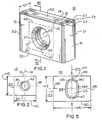
- Figure 1 is an isometric view of a green part fabricated in accordance with the method and apparatus of the subject invention and sintered to form a cutting insert;
- Figure 2 is a front view of the cutting insert shown in Figure 1 ;
- Figure 3 is a sectional view along lines "III-III" in Figure 1 ;
- Figure 4 is an isometric view of an unsintered green part fabricated in accordance with the method and apparatus of the subject invention
- Figure 5 is a front view of the unsintered green form shown in Figure 4 ;
- Figure 6 is a schematic of the parts of a die press in accordance with the subject invention.
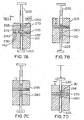
- Figures 7A-7F illustrate the sequence of die part positions to form a green part in accordance with the subject invention
- Figure 8 is a view of the die along lines "VIII-VIII" in Figure 7A ;
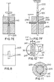
- Figure 9 is a cross-sectional view of the die illustrating the profile of the core rods in accordance with one embodiment of the subject invention.
- Figure 10 is a cross-sectional view along the lines "X-X" in Figure 9 ;
- Figure 11 is a cross-sectional view along lines "XI-XI" in Figure 9 ;
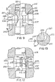
- Figure 12 is a cross-sectional view of the die illustrating the profile of the core rods in accordance with an alternate embodiment of the invention.
- Figure 13 is an enlarged view of the encircled area in Figure 12 with the core rod parts in the closed position.
- Figure 1 is an isometric view and Figure 2 is a front view of an article which, in this instance, is a cutting insert 10 after a sintering operation.
- the cutting insert 10 has a body 11 with a first lateral wall 12, an opposing second lateral wall 14 and an adjacent first end wall 18 and opposing second end wall 22 therebetween.
- the body has a top 16 and a bottom 20. At the intersection of the walls and the top is a cutting edge 23.
- the distance D1 between the first lateral wall 12 and the second lateral wall 14 defines the article depth.
- a central opening 25 with a peripheral wall 27 extends about a central axis 30 through the depth of the insert 10.
- a parting line 35 extends about the peripheral wall 27.
- the parting line 35 may extend about the peripheral wall 27 in a plane 40 perpendicular to the central axis 30. It should be appreciated that while the opening is referred to as a central opening, it is entirely possible that the opening is not centrally located but is offset from the center in one or both the vertical and horizontal direction.
- the cutting insert 10 has a major axis 70 parallel to the pressing axis (not shown) of the press with a major width W1 thereacross and has a minor axis 80 perpendicular to the pressing axis with a minor width W2 thereacross.
- the cutting insert 10 may have chip control features 50.
- the chip control features 50 may be comprised of a rake face 52 extending downwardly and away from the cutting edge 23 and a plateau wall 54 extending upwardly to a plateau 56 and away from the rake face 52 thereby defining an interrupted path that will promote chip control.
- These chip control features are generally recessed in a planar region that is perpendicular to the pressing axis of the press to be described. While the discussion has been focused on features upon the top 16 of the green part 110, it should be appreciated that similar or identical features may also exist on the bottom 18 of the green part 110.
- the sintered cutting insert 10 begins with a green part comprised of compressed metallurgical powder which, upon heating to a sintering temperature, densifies and shrinks to the size and shape of the cutting insert 10 with or without grind stock left on it.
- the metallurgical powder may be tungsten carbide powder, cobalt powder and a solid solution carbide forming powder with a fugitive binder mixed in.
- the shrinkage of the green part to the shape of the cutting insert is not uniform. This becomes particularly significant when an opening is present within the insert having an axis in a direction perpendicular to the travel direction of the press rams.
- the percentage of shrinkage of the opening during sintering is greater in the direction in which greater compression has occurred.
- the shrinkage factor of the opening and the counterbore after sintering is approximately 1.18 in a horizontal direction, which is perpendicular to the pressing axis and 1.22 in a vertical direction, which is parallel to the pressing axis. For this reason, when a circular hole is desired in the cutting insert, the hole in the unsintered green part must be non-circular. It should be noted that under different press pressures, these shrinkage factors may change.
- FIG. 1 an isometric and a front view of a green part 110 are illustrated prior to sintering to a cutting insert 10 ( Fig. 1 ).
- the reference numbers used in association with the green part 110 will be the same as those used for the cutting insert 10, but incremented by 100.
- the green part 110 has a body 111 with a first lateral wall 112, an opposing second lateral wall 114 and an adjacent first end wall 118 and opposing second end wall 122 therebetween.
- the body has a top 116 and a bottom 120.
- At the intersection of the walls 112, 114, 118, 122 and the top is a cutting edge 123.
- the distance D2 between the first lateral wall 112 and the second lateral wall 114 defines the green part 110 depth.
- a central opening 125 with a peripheral wall 127 extends about a central axis 130 through the depth D2 of the green part 110.
- a parting line 135 extends about the peripheral wall 127.
- the parting line 135 may extend about the peripheral wall 127 in a plane 140 perpendicular to the central axis 130.
- the green part 110 has a major axis 170 parallel to the pressing axis 215 with a major width W3 thereacross and has a minor axis 180 perpendicular to the pressing axis 215 with a minor width W4 thereacross.
- the entire green part 110 will shrink and, therefore, the green part 110 must be specifically shaped to account for such shrinkage.
- the central opening 125 in particular, must be shaped such that, after sintering the opening 125 conforms to a desired final shape. As illustrated in Figure 1 , one such final shape of the central opening 25 is circular.
- the central opening 125 of the green part 110 it is necessary for the central opening 125 of the green part 110 to have a non-circular shape.
- that non-circular shape of the central opening 125 is oval and, in the shape of an oval racetrack having a first end 145 and a second end 147 with semi-circular shapes, which connect with a first side 149 and a second side 151 having generally straight profiles.
- Such an arrangement has been shown to produce, after sintering, a central opening 125 having a circular shape.
- the cutting insert 10 has a central opening 25 with a beveled counterbore 42.
- the beveled counterbore 42 conforms to the shape of the central opening 25 and, as a result, the counterbore 142 ( Figure 5 ) of the green part 110 should be formed to a shape similar to the oval shaped central opening 125.
- a cutting insert 10 having a central opening 25 in the shape of a circle which is formed by sintering a green part 110 having a central opening 125 in the shape of an oval.
- the opening 25 ( Figure 1 ) in the sintered cutting insert may not need to be circular or, as previously mentioned, may not need to be centrally located. Under those circumstances it should be appreciated that the green part will be formed accordingly.
- the press for producing such a green part, and the method of utilizing such a press, will now be described.
- FIG. 6 illustrates a cross-sectional sketch of a press 200 used to produce a green part in accordance with the subject invention.
- the press 200 has a die 205 with a cavity 210 extending therethrough along the pressing axis 215 with a top ram 220 and a bottom ram 225 independently movable within the cavity to define a compression region 230.
- a removable core rod 235 is insertable within a core bore 240 through the cavity 210 at the compression region 230 in a direction perpendicular to the pressing axis 215.
- the core rod 235 has its own longitudinal axis 245 transverse to the pressing axis 215.
- the core rod 235 is comprised of a shaft 250 having a non-circular cross-section (not shown in Figure 6 ) to impart a non-circular hole within the green part 110 ( Figure 5 ).
- Figures 7A-7F illustrate the steps in accordance with one embodiment of the subject invention for fabricating a green part 110.
- Figure 7A illustrates one step associated with the method of fabricating an article similar to the green part 110 shown in Figure 5 having a central opening 125.
- the article is fabricated using a press with a uni-axial press motion.
- the bottom ram 225 is positioned within the cavity 210 below the core bore 240, while the top ram 220 is positioned outside of the cavity 210.
- the removable core rod 235 is then positioned through the core bore 240 of the cavity 210.
- the cavity 210 is then filled with a predetermined amount of metallurgical powder 260 to form a powder bed 265 having opposite sides 270, 272.
- the metallurgical powder 260 is positioned about the core rod 235 to control the location of the central opening 25 ( Figure 1 ) after sintering.
- the position of the powder 260 is obtained through the elevation of the bottom ram 225 and/or the movement of the die 205 up or down. Generally the powder 260 will be positioned such that the opening 25 ( Fig.
- the opening 25 may be offset above, below or to the side of the geometric center by placement of the powder 260, or to the side of the geometric center, or by displacement of the core rod 235 to an offset position, by changing the die so the axis of the bore of the core rod is offset from the pressing axis.
- the die 205 is moved up and down relative to the top ram 220 and the bottom ram 225 to substantially uniformly distribute the metallurgical powder 260 within the cavity 210.
- the step of positioning the metallurgical powder 260 about the core rod 235 may be comprised of centering the metallurgical powder 260 about the core rod 235, as illustrated in Figure 7C .
- the top ram 220 is moved down and the bottom ram 225 is moved up against the metallurgical powder 260 to uniformly compress the metallurgical powder 260 about the core rod 235 to produce a green part 110 ( Figure 5 ).
- the top ram 220 and the bottom ram 225 may be moved equal distances or different distances to compress the green part 110, depending upon the circumstances.
- the green part 110 is formed to be sintered into a cutting insert 10.
- the process so far described utilizes a split core rod 235 comprised of a first segment 237 and a second segment 239 that meet within the cavity 210 of the die 205.
- top ram 220 and the bottom ram 225 are retracted, as illustrated in Figure 7E , a predetermined amount to allow decompression of the green part 110.
- the core rod 235 is retracted from within the cavity 210 such that the green part 110 is no longer held captive by the core rod 235 extending through the central opening 125.
- the green part 110 may be ejected from the die 205, as illustrated in Figure 7F .
- the top ram 220 is retracted completely from the cavity 210 and the bottom ram 225 is advanced until the green part 110 is ejected from the die 205.
- the top ram 220 and the bottom ram 225 may move simultaneously or they may move sequentially depending upon the desired operating conditions.
- Figure 8 illustrates a top view of the die 205 along arrows "VIII-VIII" in Figure 7A . It is apparent that the cavity 210 of the die 205 is rectangular, which is the shape of the green part 110 ( Fig.4 ) prior to decompression and sintering.
- the core rod 235 has been illustrated as a split type core rod 235 having two halves which meet within the cavity 210 to defme the opening within the green part 110.
- the removable core rod 235 it is entirely possible for the removable core rod 235 to be of the split pin type, wherein the core rod 235 has a matable first segment 237 and second segment 239 and the step of positioning the removable core rod 235 through the core bore 240 into the cavity 210 is comprised of moving the matable first segment 237 into the cavity 210 from one side of the die 205, and moving the matable second segment 239 into cavity 210 from the other side of the die 205 causing the two segments to meet within the cavity 210.
- the matable segments 237, 239 of the core rod 235 are moved into the cavity 210 such that they may contact each other along the pressing axis 215 of the cavity 210. As illustrated in Figure 12 and as will be discussed further, it is possible for the core rod segments 237, 239 to meet at a location other than along the pressing axis 215.
- the step of moving the top ram 220 down and the bottom ram 225 up to compress the metallurgical powder 260 is comprised of forming the central bore 125 ( Figure 5 ) of the green part 110 into a non-circular shape such that, when the green part 110 is sintered, the opening 125 will shrink a greater percentage along the pressing axis 215 ( Figures 5 and 6 ) than in a direction perpendicular to the pressing axis 215.
- the non-circular shape 125 is an oval racetrack and the resulting sintered shape is a circle however it should be understood that the non-circular shape may be any number of different configurations depending upon the desired sintered shape.
- the step of moving the top ram 220 down and the bottom ram 225 up to compress the metallurgical powder 260 may be further comprised of forming in at least one side 270 ( Fig. 7A ) of the powder bed 265 a counterbore 142 ( Fig.5 ) coaxial with the central opening 125. Additionally, the step of moving the top ram 220 down and the bottom ram 225 up to compress the metallurgical powder 260 may be comprised of imparting chip control features 150 to at least one edge 116 of the green part 110, as illustrated in Figure 4 .
- the chip control features 150 may be comprised of a rake face 152 extending downwardly and away from the cutting edge 123 and a plateau wall 154 extending upwardly to a plateau 156 and away from the rake face 152 thereby defining an interrupted path that will promote chip control.
- the top ram 220 and/or the bottom ram 225 must have a face with a profile complimentary to that of these chip control features or any other features 150 that may be imparted to the green part 110.
- the part is intended to be sintered, whereby a cutting insert is produced.
- an insert fabricated in accordance with the subject invention will have a parting line within the wall of the central opening extending through the insert.
- central feed body 20 to reduce wear caused by a material flow, is not solely affected by the spacing distance that bars are positioned adjacent each other.
- the effectiveness of central feed body 20, according to the present invention, to reduce wear by a material flow is a function in part of the spacing distance between hard material bars 50 on the central feed body, as well as the design, number, shape, configuration and location of the bars 50 on the central feed body 20 in relation to angles of incidence of a material flow against, over and around the central feed body 20, and the alloy composition of bars 50. Also, it should be appreciated that the hard material compositions used in the bars does not have to be used consistently throughout either the impeller shoe or central feed body.
- FIG. 9 illustrates a split core rod 235 having a first segment 237 and a second segment 239 movable within the core bore 240 along the core bore longitudinal axis 245.
- the core rod 235 within the region of the cavity 210 has a cross-sectional configuration identical to the cross-sectional configuration of the central opening 125 illustrated in Figure 5 .
- This cross-sectional area, shown in Figure 10 has a the shape of an oval and, is comprised of a first end 305 and a second end 307 having semi-circular shapes and connected by a first straight side 309 and second straight side 311 connecting therebetween.
- the core rod 235 has a major axis 295 parallel to the pressing axis 215 with a major width W5 thereacross and has a minor axis 297 perpendicular to the pressing axis 215 with a minor width W6 thereacross
- Figure 11 illustrates a cross sectional view of the core rod 235 shown in Figure 9 to show that the shaft 250 of the core rod 235 may have a key 315 which aligns with the channel 320 in the die 205 to properly orient the core rod 235 within the die 205.
- first segment 237 and a second segment 239 each have complementary ends 251, 255 that meet to form a continuous core rod (not shown).
- End 251 of the first segment 237 has a curved indentation 252, while end 255 of the second segment 239 has a complementary curved projection 257 to mate with the indentation 252.
- the first segment 237 also has a peripheral planar ring 253 surrounding the indentation 252, while the second segment 239 has a complementary peripheral planar ring 259 surrounding the projection 257 such that the planar rings 253, 259 meet and contact one another.
- an end 251 of the core rod first segment 237 has a central cavity 262 surrounded by a wall 267 to define a cavity contour 271.
- End 255 of the core rod second segment 239 has a projection 280 in the shape of the cavity contour 271 but reduced such that the second segment 239 fits within the first segment 237.
- the end 251 of the first segment 237 may have a concave surface 275 to promote contact between the first segment 237 and the second segment 239.
- Figure 13 illustrates an enlarged section of the encircled area in Figure 12 highlighting the manner in which the end 251 of the first segment 237 mates with the end 255 of the second segment 239.
- the projection 280 of the core rod second segment 239 has exterior walls 285 about a central axis 245 and the walls 285 have a taper T between 1-20° relative to the core rod longitudinal axis 245 to promote mating with the cavity 262 of the first segment 237.
- the core rod 235 is comprised of two mating parts, it should be appreciated that it is entirely possible for the core rod 235 to be a single segment that may extend through the cavity 210. However, that there must be clearance available on the sides of the die 205 such that the core rod 235 may be retracted far enough to release the green part 110.
- the finished cutting insert 10 has a counterbore 42 which corresponds to the counterbore 142 of green part 110 in Figure 5 .
- the counterbore 142 was imparted to the green part 110 by a counterbore portion 290 ( Fig. 9 ) corresponding to the shape of the counterbore 142 in the green part 110.
- an opposing counterbore portion 292 may be included on the opposite side of the core rod 235.
- any article produced in accordance with the above invention utilizing a core rod 235 having two parts which contact one another within the cavity 210 will have a parting line 135, as illustrated in Figure 4 . It may be possible to remove this parting line 135 prior to sintering but, nevertheless, this parting line 135 exists as a result of the molding process. Furthermore, if the parting line 135 is not removed from the green part, then the parting line 35 ( Figure 1 ) will remain with the sintered article.
Landscapes
- Engineering & Computer Science (AREA)
- Manufacturing & Machinery (AREA)
- Mechanical Engineering (AREA)
- Powder Metallurgy (AREA)
- Press-Shaping Or Shaping Using Conveyers (AREA)
- Perforating, Stamping-Out Or Severing By Means Other Than Cutting (AREA)
Abstract
Description
- The invention is directed to the field of pressing of powders to make inserts.
- Powder metallurgy has become a viable alternative to traditional casting and machining techniques. In the powder metallurgy process, one or more powder metals and/or ceramics, with or without a fugitive binder, are added to a mold and then compacted under very high pressures, typically between about 20-80 tons per 6,45 cm2. The compacted part is ejected from the mold as a "green" part. The green part is then sintered in a furnace operating at temperatures of typically 1100°-1950°C. The sintering temperature depends upon the composition of the powder mixture. For example, cemented carbide and cermets are typically sintered at 1350°-1450°C while ceramics are typically sintered at 1500°-1950°C. The sintering process effectively welds together all of the individual powder grains into a solid mass of considerable mechanical strength with little, if any, porosity. The powder metallurgy process can be generally used to make parts from any type of powder and sintering temperatures are primarily determined by the temperature of fusion of each powder type. Powder metallurgy parts have several significant advantages over traditional cast or machine parts. Powder metallurgy parts can be molded with very intricate features that eliminate much of the grinding that is required with conventional fabrication. Powder metallurgy parts can be molded to tolerances within about four or five thousandths of an inch, a level of precision acceptable for many machined surfaces. Surfaces which require tighter tolerances can be quickly and easily ground since only a small amount of surface material need be removed. Surfaces of powder metallurgy parts are very smooth and offer an excellent finish which is suitable for bearing surfaces.
- The powder metallurgy process is also very efficient compared with other processes. Powder metallurgy processes are capable of typically producing between 200-2,000 pieces per hour, depending on the size and of the degree of complexity. The molds are typically capable of thousands of service hours before wearing out and requiring replacement. Since almost all of the powder which enters the mold becomes part of the finished product, the powder metallurgy process is about 97% material efficient. During sintering, it is only necessary to heat the green part to a temperature which permits fusion of the powder granules. This temperature is typically much lower than the melting points of the powders, and so sintering is considerably more energy efficient than a comparable casting process.
- In spite of the many advantages of powder metallurgy parts, the fabrication of powder metallurgy parts suffers from certain drawbacks. Powder metallurgy parts are molded under high pressures which are obtained through large opposing forces that are generated by the molding equipment. These forces are applied by mold elements which move back and forth in opposing vertical directions along a pressing axis. The powder metallurgy parts produced thereby have previously necessarily had a "vertical" profile. Since mold elements move back and forth in opposing vertical directions, powder metallurgy parts formed with transverse features, i.e., holes, grooves, undercuts, cross-cuts or threads, would inhibit mold release and therefore these features would not be pressed into the green part. Such profile features then required a secondary machining step which added greatly to the cost of the part and creates an economic disincentive to fabricate parts using powder metallurgy.
-
JP-A 10-118796 - A method and apparatus are desired capable of effectively imparting a through hole with or without a counterbore through a cutting insert using powder pressing techniques.
- The invention is directed to a method of fabricating an article having an opening using a press with a uni-axial press motion, according to claim 1.
- The invention is further directed to a uni-axial press for forming a green part from metallurgical powder, according to claim 17.
- Finally, the invention is directed to an article comprised of compacted metallurgical powder according to claim 24.
-
Figure 1 is an isometric view of a green part fabricated in accordance with the method and apparatus of the subject invention and sintered to form a cutting insert; -
Figure 2 is a front view of the cutting insert shown inFigure 1 ; -
Figure 3 is a sectional view along lines "III-III" inFigure 1 ; -
Figure 4 is an isometric view of an unsintered green part fabricated in accordance with the method and apparatus of the subject invention; -
Figure 5 is a front view of the unsintered green form shown inFigure 4 ; -
Figure 6 is a schematic of the parts of a die press in accordance with the subject invention; -
Figures 7A-7F illustrate the sequence of die part positions to form a green part in accordance with the subject invention; -
Figure 8 is a view of the die along lines "VIII-VIII" inFigure 7A ; -
Figure 9 is a cross-sectional view of the die illustrating the profile of the core rods in accordance with one embodiment of the subject invention; -
Figure 10 is a cross-sectional view along the lines "X-X" inFigure 9 ; -
Figure 11 is a cross-sectional view along lines "XI-XI" inFigure 9 ; -
Figure 12 is a cross-sectional view of the die illustrating the profile of the core rods in accordance with an alternate embodiment of the invention; and -
Figure 13 is an enlarged view of the encircled area inFigure 12 with the core rod parts in the closed position. -
Figure 1 is an isometric view andFigure 2 is a front view of an article which, in this instance, is a cutting insert 10 after a sintering operation. Thecutting insert 10 has abody 11 with a firstlateral wall 12, an opposing secondlateral wall 14 and an adjacentfirst end wall 18 and opposingsecond end wall 22 therebetween. The body has atop 16 and abottom 20. At the intersection of the walls and the top is acutting edge 23. The distance D1 between the firstlateral wall 12 and the secondlateral wall 14 defines the article depth. Acentral opening 25 with aperipheral wall 27 extends about acentral axis 30 through the depth of theinsert 10. As a result of the pressing operation to be described herein, aparting line 35 extends about theperipheral wall 27. Theparting line 35 may extend about theperipheral wall 27 in aplane 40 perpendicular to thecentral axis 30. It should be appreciated that while the opening is referred to as a central opening, it is entirely possible that the opening is not centrally located but is offset from the center in one or both the vertical and horizontal direction. - The
cutting insert 10 has a major axis 70 parallel to the pressing axis (not shown) of the press with a major width W1 thereacross and has aminor axis 80 perpendicular to the pressing axis with a minor width W2 thereacross. - The
cutting insert 10 may have chip control features 50. In one instance, thechip control features 50 may be comprised of arake face 52 extending downwardly and away from thecutting edge 23 and a plateau wall 54 extending upwardly to a plateau 56 and away from therake face 52 thereby defining an interrupted path that will promote chip control. These chip control features are generally recessed in a planar region that is perpendicular to the pressing axis of the press to be described. While the discussion has been focused on features upon thetop 16 of thegreen part 110, it should be appreciated that similar or identical features may also exist on thebottom 18 of thegreen part 110. - What has so far been described is a cutting
insert 10 after sintering. Formation of the sintered cuttinginsert 10 begins with a green part comprised of compressed metallurgical powder which, upon heating to a sintering temperature, densifies and shrinks to the size and shape of the cuttinginsert 10 with or without grind stock left on it. For example, the metallurgical powder may be tungsten carbide powder, cobalt powder and a solid solution carbide forming powder with a fugitive binder mixed in. - As a result of the non-uniformity of compression within the body of the green part, the shrinkage of the green part to the shape of the cutting insert is not uniform. This becomes particularly significant when an opening is present within the insert having an axis in a direction perpendicular to the travel direction of the press rams. In particular, the percentage of shrinkage of the opening during sintering is greater in the direction in which greater compression has occurred. Under certain circumstances, such as when the green part is comprised of cemented tungsten carbide, the shrinkage factor of the opening and the counterbore after sintering is approximately 1.18 in a horizontal direction, which is perpendicular to the pressing axis and 1.22 in a vertical direction, which is parallel to the pressing axis. For this reason, when a circular hole is desired in the cutting insert, the hole in the unsintered green part must be non-circular. It should be noted that under different press pressures, these shrinkage factors may change.
- Directing attention to
Figures 4 and5 , an isometric and a front view of agreen part 110 are illustrated prior to sintering to a cutting insert 10 (Fig. 1 ). For purposes of discussion and unless otherwise specified, the reference numbers used in association with thegreen part 110 will be the same as those used for the cuttinginsert 10, but incremented by 100. - The
green part 110 has a body 111 with a firstlateral wall 112, an opposing secondlateral wall 114 and an adjacentfirst end wall 118 and opposingsecond end wall 122 therebetween. The body has a top 116 and a bottom 120. At the intersection of thewalls cutting edge 123. The distance D2 between the firstlateral wall 112 and the secondlateral wall 114 defines thegreen part 110 depth. Acentral opening 125 with aperipheral wall 127 extends about acentral axis 130 through the depth D2 of thegreen part 110. As a result of the pressing operation, aparting line 135 extends about theperipheral wall 127. Theparting line 135 may extend about theperipheral wall 127 in a plane 140 perpendicular to thecentral axis 130. - The
green part 110 has a major axis 170 parallel to thepressing axis 215 with a major width W3 thereacross and has aminor axis 180 perpendicular to thepressing axis 215 with a minor width W4 thereacross. - During sintering, the entire
green part 110 will shrink and, therefore, thegreen part 110 must be specifically shaped to account for such shrinkage. Thecentral opening 125, in particular, must be shaped such that, after sintering theopening 125 conforms to a desired final shape. As illustrated inFigure 1 , one such final shape of thecentral opening 25 is circular. - To provide a
central opening 25 having a circular shape, it is necessary for thecentral opening 125 of thegreen part 110 to have a non-circular shape. As illustrated inFigures 4 and5 , that non-circular shape of thecentral opening 125 is oval and, in the shape of an oval racetrack having afirst end 145 and asecond end 147 with semi-circular shapes, which connect with afirst side 149 and asecond side 151 having generally straight profiles. Such an arrangement has been shown to produce, after sintering, acentral opening 125 having a circular shape. - As illustrated in
Figures 1-3 , the cuttinginsert 10 has acentral opening 25 with abeveled counterbore 42. Thebeveled counterbore 42 conforms to the shape of thecentral opening 25 and, as a result, the counterbore 142 (Figure 5 ) of thegreen part 110 should be formed to a shape similar to the oval shapedcentral opening 125. - What has so far been described is a cutting
insert 10 having acentral opening 25 in the shape of a circle which is formed by sintering agreen part 110 having acentral opening 125 in the shape of an oval. In some instances the opening 25 (Figure 1 ) in the sintered cutting insert may not need to be circular or, as previously mentioned, may not need to be centrally located. Under those circumstances it should be appreciated that the green part will be formed accordingly. The press for producing such a green part, and the method of utilizing such a press, will now be described. -
Figure 6 illustrates a cross-sectional sketch of apress 200 used to produce a green part in accordance with the subject invention. Thepress 200 has a die 205 with acavity 210 extending therethrough along thepressing axis 215 with atop ram 220 and abottom ram 225 independently movable within the cavity to define acompression region 230. Aremovable core rod 235 is insertable within acore bore 240 through thecavity 210 at thecompression region 230 in a direction perpendicular to thepressing axis 215. Thecore rod 235 has its ownlongitudinal axis 245 transverse to thepressing axis 215. Thecore rod 235 is comprised of ashaft 250 having a non-circular cross-section (not shown inFigure 6 ) to impart a non-circular hole within the green part 110 (Figure 5 ). -
Figures 7A-7F illustrate the steps in accordance with one embodiment of the subject invention for fabricating agreen part 110. In particular,Figure 7A illustrates one step associated with the method of fabricating an article similar to thegreen part 110 shown inFigure 5 having acentral opening 125. The article is fabricated using a press with a uni-axial press motion. - In
Figure 7A , thebottom ram 225 is positioned within thecavity 210 below the core bore 240, while thetop ram 220 is positioned outside of thecavity 210. Theremovable core rod 235 is then positioned through the core bore 240 of thecavity 210. Thecavity 210 is then filled with a predetermined amount ofmetallurgical powder 260 to form apowder bed 265 havingopposite sides metallurgical powder 260 is positioned about thecore rod 235 to control the location of the central opening 25 (Figure 1 ) after sintering. The position of thepowder 260 is obtained through the elevation of thebottom ram 225 and/or the movement of the die 205 up or down. Generally thepowder 260 will be positioned such that the opening 25 (Fig. 1 ), after sintering, will be at the geometric center of the cutting insert.
However, when desired, theopening 25 may be offset above, below or to the side of the geometric center by placement of thepowder 260, or to the side of the geometric center, or by displacement of thecore rod 235 to an offset position, by changing the die so the axis of the bore of the core rod is offset from the pressing axis. - Directing attention to
Figure 7B , subsequent to the step of filling thecavity 210 withmetallurgical powder 260, thedie 205 is moved up and down relative to thetop ram 220 and thebottom ram 225 to substantially uniformly distribute themetallurgical powder 260 within thecavity 210. - The step of positioning the
metallurgical powder 260 about thecore rod 235 may be comprised of centering themetallurgical powder 260 about thecore rod 235, as illustrated inFigure 7C . - Directing attention to
Figure 7D , thetop ram 220, is moved down and thebottom ram 225 is moved up against themetallurgical powder 260 to uniformly compress themetallurgical powder 260 about thecore rod 235 to produce a green part 110 (Figure 5 ). Thetop ram 220 and thebottom ram 225 may be moved equal distances or different distances to compress thegreen part 110, depending upon the circumstances. Thegreen part 110 is formed to be sintered into a cuttinginsert 10. The process so far described utilizes asplit core rod 235 comprised of afirst segment 237 and asecond segment 239 that meet within thecavity 210 of thedie 205. When thepowder 260 is compressed against thecore rod 235, adiscontinuity 236 at the point thefirst segment 237 and thesecond segment 239 meet will cause a parting line 135 (Fig. 5 ) to be imparted within theopening 125 of thegreen part 110. This feature is unique to cutting inserts produced using a uni-axial cross-hole press in accordance with the subject invention. - Once the
metallurgical powder 260 is compressed, thetop ram 220 and thebottom ram 225 are retracted, as illustrated inFigure 7E , a predetermined amount to allow decompression of thegreen part 110. - In
Figure 7F , thecore rod 235 is retracted from within thecavity 210 such that thegreen part 110 is no longer held captive by thecore rod 235 extending through thecentral opening 125. At this point, thegreen part 110 may be ejected from thedie 205, as illustrated inFigure 7F . In order to eject thegreen part 110 from thedie 205, thetop ram 220 is retracted completely from thecavity 210 and thebottom ram 225 is advanced until thegreen part 110 is ejected from thedie 205. Thetop ram 220 and thebottom ram 225 may move simultaneously or they may move sequentially depending upon the desired operating conditions. -
Figure 8 illustrates a top view of thedie 205 along arrows "VIII-VIII" inFigure 7A . It is apparent that thecavity 210 of thedie 205 is rectangular, which is the shape of the green part 110 (Fig.4 ) prior to decompression and sintering. - It should be noted that throughout these processes, the
core rod 235 has been illustrated as a splittype core rod 235 having two halves which meet within thecavity 210 to defme the opening within thegreen part 110. Directing attention toFigure 9 , it is entirely possible for theremovable core rod 235 to be of the split pin type, wherein thecore rod 235 has a matablefirst segment 237 andsecond segment 239 and the step of positioning theremovable core rod 235 through the core bore 240 into thecavity 210 is comprised of moving the matablefirst segment 237 into thecavity 210 from one side of thedie 205, and moving the matablesecond segment 239 intocavity 210 from the other side of thedie 205 causing the two segments to meet within thecavity 210. Thematable segments core rod 235 are moved into thecavity 210 such that they may contact each other along thepressing axis 215 of thecavity 210. As illustrated inFigure 12 and as will be discussed further, it is possible for thecore rod segments pressing axis 215. - As previously mentioned, shrinkage during sintering of the green part 110 (
Fig. 4 ) is not uniform across the cutting insert 10 (Fig. 1 ) and, as a result, the step of moving thetop ram 220 down and thebottom ram 225 up to compress themetallurgical powder 260 is comprised of forming the central bore 125 (Figure 5 ) of thegreen part 110 into a non-circular shape such that, when thegreen part 110 is sintered, theopening 125 will shrink a greater percentage along the pressing axis 215 (Figures 5 and6 ) than in a direction perpendicular to thepressing axis 215. In a preferred embodiment, thenon-circular shape 125 is an oval racetrack and the resulting sintered shape is a circle however it should be understood that the non-circular shape may be any number of different configurations depending upon the desired sintered shape. - The step of moving the
top ram 220 down and thebottom ram 225 up to compress themetallurgical powder 260 may be further comprised of forming in at least one side 270 (Fig. 7A ) of the powder bed 265 a counterbore 142 (Fig.5 ) coaxial with thecentral opening 125. Additionally, the step of moving thetop ram 220 down and thebottom ram 225 up to compress themetallurgical powder 260 may be comprised of imparting chip control features 150 to at least oneedge 116 of thegreen part 110, as illustrated inFigure 4 . In one instance, the chip control features 150 may be comprised of arake face 152 extending downwardly and away from thecutting edge 123 and aplateau wall 154 extending upwardly to a plateau 156 and away from therake face 152 thereby defining an interrupted path that will promote chip control. To accomplish this, thetop ram 220 and/or thebottom ram 225 must have a face with a profile complimentary to that of these chip control features or anyother features 150 that may be imparted to thegreen part 110. - Finally, it should be appreciated that after the green part is formed, the part is intended to be sintered, whereby a cutting insert is produced.
- While what has been discussed so far is a method of producing a green part that will be sintered into a cutting insert, the article formed by this process is also believed to be novel. Unlike other conventionally fabricated inserts, an insert fabricated in accordance with the subject invention will have a parting line within the wall of the central opening extending through the insert.
- The capacity of
central feed body 20 according to the present invention, to reduce wear caused by a material flow, is not solely affected by the spacing distance that bars are positioned adjacent each other. The effectiveness ofcentral feed body 20, according to the present invention, to reduce wear by a material flow, is a function in part of the spacing distance between hard material bars 50 on the central feed body, as well as the design, number, shape, configuration and location of thebars 50 on thecentral feed body 20 in relation to angles of incidence of a material flow against, over and around thecentral feed body 20, and the alloy composition ofbars 50. Also, it should be appreciated that the hard material compositions used in the bars does not have to be used consistently throughout either the impeller shoe or central feed body. Bars that are positioned on theshoes 14 orcentral feed bodies 20 that are subjected to An important feature of the subject invention is the design and operation of thecore rod 235.Figure 9 illustrates asplit core rod 235 having afirst segment 237 and asecond segment 239 movable within the core bore 240 along the core borelongitudinal axis 245. Thecore rod 235 within the region of thecavity 210 has a cross-sectional configuration identical to the cross-sectional configuration of thecentral opening 125 illustrated inFigure 5 . This cross-sectional area, shown inFigure 10 , has a the shape of an oval and, is comprised of afirst end 305 and asecond end 307 having semi-circular shapes and connected by a firststraight side 309 and second straight side 311 connecting therebetween. Thecore rod 235 has amajor axis 295 parallel to thepressing axis 215 with a major width W5 thereacross and has aminor axis 297 perpendicular to thepressing axis 215 with a minor width W6 thereacross -
Figure 11 illustrates a cross sectional view of thecore rod 235 shown inFigure 9 to show that theshaft 250 of thecore rod 235 may have a key 315 which aligns with thechannel 320 in thedie 205 to properly orient thecore rod 235 within thedie 205. - Directing attention to
Figure 9 , thefirst segment 237 and asecond segment 239 each havecomplementary ends End 251 of thefirst segment 237 has acurved indentation 252, whileend 255 of thesecond segment 239 has a complementarycurved projection 257 to mate with theindentation 252. Thefirst segment 237 also has a peripheralplanar ring 253 surrounding theindentation 252, while thesecond segment 239 has a complementary peripheralplanar ring 259 surrounding theprojection 257 such that theplanar rings - In an alternate embodiment, as illustrated in
Figures 12 and 13 , anend 251 of the core rodfirst segment 237 has acentral cavity 262 surrounded by awall 267 to define a cavity contour 271.End 255 of the core rodsecond segment 239 has aprojection 280 in the shape of the cavity contour 271 but reduced such that thesecond segment 239 fits within thefirst segment 237. Theend 251 of thefirst segment 237 may have aconcave surface 275 to promote contact between thefirst segment 237 and thesecond segment 239. -
Figure 13 illustrates an enlarged section of the encircled area inFigure 12 highlighting the manner in which theend 251 of thefirst segment 237 mates with theend 255 of thesecond segment 239. Theprojection 280 of the core rodsecond segment 239 hasexterior walls 285 about acentral axis 245 and thewalls 285 have a taper T between 1-20° relative to the core rodlongitudinal axis 245 to promote mating with thecavity 262 of thefirst segment 237. - While as discussed so far, the
core rod 235 is comprised of two mating parts, it should be appreciated that it is entirely possible for thecore rod 235 to be a single segment that may extend through thecavity 210. However, that there must be clearance available on the sides of the die 205 such that thecore rod 235 may be retracted far enough to release thegreen part 110. - Returning to
Figure 1 , the finished cuttinginsert 10 has acounterbore 42 which corresponds to thecounterbore 142 ofgreen part 110 inFigure 5 . Thecounterbore 142 was imparted to thegreen part 110 by a counterbore portion 290 (Fig. 9 ) corresponding to the shape of thecounterbore 142 in thegreen part 110. In the event a counterbore is desired on both sides of the insert, an opposing counterbore portion 292 (Fig. 9 ) may be included on the opposite side of thecore rod 235. - As mentioned, any article produced in accordance with the above invention utilizing a
core rod 235 having two parts which contact one another within thecavity 210 will have aparting line 135, as illustrated inFigure 4 . It may be possible to remove thisparting line 135 prior to sintering but, nevertheless, thisparting line 135 exists as a result of the molding process. Furthermore, if theparting line 135 is not removed from the green part, then the parting line 35 (Figure 1 ) will remain with the sintered article.
Claims (25)
- A method of fabricating an article made of metallurgical powder using a press with a uni-axial press motion, wherein the article is a green part intended to be sintered and wherein the press has a die with a cavity extending therethrough along a pressing axis with a top ram and a bottom ram independently movable along the pressing axis within the cavity to define a compression region and furthermore having a removable core rod insertable within a core bore through the cavity at the compression region in a direction perpendicular to the pressing axis, the method comprises the steps of:a) positioning the bottom ram within the cavity below the core bore and positioning the top ram outside of the cavity;b) positioning the removable core rod through the core bore such that the core rod extends completely through the cavity;c) filling the cavity with a predetermined amount of metallurgical powder to form a powder bed having opposing sides;d) moving the die cavity relative to the top ram and the bottom ram to substantially uniformly distribute the powder within the cavity;e) positioning the metallurgical powder about the core rod to control the location of the opening after sintering;f) moving the top ram down and moving the bottom ram up against the metallurgical powder along the pressing axis to uniformly compress the metallurgical powder about the core rod to produce the green part, wherein the green part has a top and bottom and sides therebetween and the green part has a major axis parallel to the pressing axis with a major width thereacross and also has a minor axis perpendicular to the pressing axis with a minor width thereacross, and the green part has an opening with a longitudinal axis perpendicular to the pressing axis of the die and the opening has a non-circular shape;g) retracting the core rod from within the cavity; andh) ejecting the green part from the die,characterized in that the opening has a non-circular shape in the form of an oval racetrack having two opposing straight segments parallel to the pressing axis and two opposing semi-circles connecting the ends of the straight segments.
- The method according to claim 1 wherein the step of positioning the removable core rod through the core bore into the cavity is comprised of moving the matable first segment into the cavity from one side of the die and the matable second segment into the cavity from the other side of the die causing the two segments to meet within the cavity.
- The method according to claim 2 wherein the mateable segments of the core rod are moved into the cavity such that they contact each other along the pressing axis of the cavity.
- The method according to claim 1, wherein the step of moving the die relative to the top ram and the bottom ram to substantially uniformly distribute the powder within the cavity comprises moving the die up and down relative to the top ram and the bottom ram.
- The method according to claim 1 wherein the step of positioning the metallurgical powder about the core rod is comprised of centering the metallurgical powder about the core rod.
- The method according to claim 1 wherein the step of moving the top ram down and the bottom ram up to compress the powder is comprised of moving the top ram down and the bottom ram up by an equal amount.
- The method according to claim 1 wherein the step of ejecting the green part from the die is comprised of retracting the top ram completely from the cavity and advancing the bottom ram until the green part is ejected from the die.
- The method according to claim 7 wherein the top ram and the bottom ram move simultaneously.
- The method according to claim 7 wherein the top ram and the bottom ram move sequentially.
- The method according to claim 1 wherein the step of moving the top ram down and the bottom ram up to compress the powder is comprised of forming the opening of the green part into the non-circular shape such that when the green part is sintered the opening will shrink a greater percentage in a direction parallel to the pressing axis than in a direction perpendicular to the pressing axis.
- The method according to claim 10 wherein when sintered the green part will shrink and the opening will deform to a predetermined final shape.
- The method according to claim 11 wherein the non-circular shape, after sintering, shrinks into a circular shape.
- The method according to claim 1 wherein the step of moving the top ram down and the bottom ram up to compress the powder is further comprised of forming in at least one side of the powder bed a counterbore co-axial with the opening.
- The method according to claim 1 wherein the green part is formed to be sintered into a cutting insert and wherein the step of moving the top ram down and the bottom ram up to compress the powder is further comprised of imparting chip control features to at least one of the top or the bottom of the green part.
- The method according to claim 13 wherein the chip control feature is comprised of a rake face extending downwardly and away from a cutting edge and a plateau wall extending upwardly and away from the rake face thereby defining an interrupted path that will promote chip control.
- The method according to claim 1 further including the step of sintering the green part to form a cutting insert.
- A uni-axial press for forming a green part from compressed metallurgical powder, wherein the press comprises:a) a die with a cavity extending therethrough along a pressing axis with a top ram and a bottom ram independently movable along the pressing axis within the cavity to define a compression region andb) a removable core rod insertable to define a core bore at the compression region in a direction perpendicular to the pressing axis; wherein the core rod is adapted to extend completely through the cavity;wherein the core rod has a longitudinal axis and comprises a shaft having a non-circular cross-section to impart an identical opening within the green part for accommodating shrinkage of the opening, and
wherein the core rod is comprised of a first segment having an end with an indentation and a second segment having an end with a protrusion, wherein the protrusion axially contacts and engages the indentation to form a continuous core rod,
characterized in that the core rod has a cross-sectional shape with a major axis parallel to the pressing axis and a major width thereacross and with a minor axis perpendicular to the pressing axis with a minor width thereacross, wherein the cross-sectional shape is an oval having two straight sides connected by semi-circular ends and wherein the straight sides are parallel to the major axis of the core rod, and wherein the straight sides of the core rod are aligned such that they are parallel to the pressing axis. - The uni-axial press according to claim 17 wherein the ends of the first segment and the second segment engage one another at the center of the die cavity.
- The uni-axial press according to claim 18 wherein the first segment has an end with a curved indentation and the second segment has an end with a complimentary curved projection to mate with the indentation.
- The uni-axial press according to claim 19 wherein the first segment has a peripheral planar ring surrounding the indentation and the second segment has a complimentary peripheral planar ring surrounding the projection such that the planar rings meet to contact one another.
- The uni-axial press according to claim 17 wherein the core rod is a single segment that may extend through the cavity.
- The uni-axial press according to claim 17 wherein a portion of the rod has an enlarged segment to impart a counterbore within the side of the green part.
- The uni-axial press according to claim 17 wherein the shaft of the core rod is keyed along the longitudinal axis within the die to properly orient the core rod within the die.
- An article comprised of green compacted metallurgical powder wherein the article has a body with a first lateral wall, an opposing second lateral wall and an adjacent first end wall and opposing second end wall therebetween, wherein the first lateral wall and second lateral wall define an article depth, wherein an opening with a peripheral wall extends about a longitudinal axis through the depth of the article, wherein the article is shaped into a green part to be sintered into a cutting insert and has a pressing axis perpendicular to the longitudinal axis, and wherein the opening has a cross-section perpendicular to the longitudinal axis, characterized in that the cross-section defines a non-circular shape in the form of an oval racetrack having two opposing straight segments parallel to the pressing axis and two opposing semi-circles connecting the ends of the straight segments.
- The article according to claim 24 wherein the opening is centered within the green part.
Priority Applications (1)
| Application Number | Priority Date | Filing Date | Title |
|---|---|---|---|
| EP09009446A EP2127785A3 (en) | 2002-11-04 | 2003-10-23 | Method and appartus for cross-hole pressing to produce cutting inserts |
Applications Claiming Priority (3)
| Application Number | Priority Date | Filing Date | Title |
|---|---|---|---|
| US287430 | 1988-12-21 | ||
| US10/287,430 US6986866B2 (en) | 2002-11-04 | 2002-11-04 | Method and apparatus for cross-hole pressing to produce cutting inserts |
| PCT/US2003/033699 WO2004041463A2 (en) | 2002-11-04 | 2003-10-23 | Method and apparatus for cross-hole pressing to produce cutting inserts |
Related Child Applications (1)
| Application Number | Title | Priority Date | Filing Date |
|---|---|---|---|
| EP09009446A Division EP2127785A3 (en) | 2002-11-04 | 2003-10-23 | Method and appartus for cross-hole pressing to produce cutting inserts |
Publications (2)
| Publication Number | Publication Date |
|---|---|
| EP1558415A2 EP1558415A2 (en) | 2005-08-03 |
| EP1558415B1 true EP1558415B1 (en) | 2009-12-30 |
Family
ID=32175695
Family Applications (2)
| Application Number | Title | Priority Date | Filing Date |
|---|---|---|---|
| EP03776529A Revoked EP1558415B1 (en) | 2002-11-04 | 2003-10-23 | Method and apparatus for cross-hole pressing to produce cutting inserts |
| EP09009446A Withdrawn EP2127785A3 (en) | 2002-11-04 | 2003-10-23 | Method and appartus for cross-hole pressing to produce cutting inserts |
Family Applications After (1)
| Application Number | Title | Priority Date | Filing Date |
|---|---|---|---|
| EP09009446A Withdrawn EP2127785A3 (en) | 2002-11-04 | 2003-10-23 | Method and appartus for cross-hole pressing to produce cutting inserts |
Country Status (12)
| Country | Link |
|---|---|
| US (2) | US6986866B2 (en) |
| EP (2) | EP1558415B1 (en) |
| JP (1) | JP2006513317A (en) |
| KR (1) | KR20050055794A (en) |
| CN (1) | CN1708371A (en) |
| AT (1) | ATE453476T1 (en) |
| BR (1) | BR0315993A (en) |
| CA (1) | CA2503367A1 (en) |
| DE (1) | DE60330793D1 (en) |
| IL (1) | IL168008A (en) |
| MX (1) | MXPA05004851A (en) |
| WO (1) | WO2004041463A2 (en) |
Families Citing this family (25)
| Publication number | Priority date | Publication date | Assignee | Title |
|---|---|---|---|---|
| KR100655639B1 (en) * | 2005-01-03 | 2006-12-11 | 이양구 | Insert for a cutting tool |
| IL166530A (en) * | 2005-01-27 | 2009-06-15 | Iscar Ltd | Method for manufacturing cutting inserts |
| DE102006020213B4 (en) * | 2006-05-02 | 2009-09-10 | Fette Gmbh | Press for producing compacts of powder material |
| KR20090110860A (en) * | 2007-02-16 | 2009-10-22 | 데이진 화-마 가부시키가이샤 | Compression tableting machine |
| US7829015B2 (en) * | 2007-05-31 | 2010-11-09 | Borgwarner Inc. | Formation of non-axial features in compacted powder metal components |
| US7931856B2 (en) * | 2007-09-04 | 2011-04-26 | Burgess-Norton Mfg. Co., Inc. | Method of manufacturing crankshaft bushing |
| US8033805B2 (en) | 2007-11-27 | 2011-10-11 | Kennametal Inc. | Method and apparatus for cross-passageway pressing to produce cutting inserts |
| US8062014B2 (en) * | 2007-11-27 | 2011-11-22 | Kennametal Inc. | Method and apparatus using a split case die to press a part and the part produced therefrom |
| KR101465291B1 (en) * | 2007-12-27 | 2014-11-26 | 산드빅 인터렉츄얼 프로퍼티 에이비 | Method of making a cutting insert with a hole for clamping |
| IL201272A0 (en) * | 2009-10-01 | 2010-05-31 | Iscar Ltd | Cutting insert and method of manufacture thereof |
| TWI458985B (en) * | 2011-02-23 | 2014-11-01 | King Yuan Electronics Co Ltd | A hard and wear-resisting probe and manufacturing method thereof |
| US9033621B2 (en) | 2011-09-19 | 2015-05-19 | Iscar, Ltd. | Cutting insert, cutting body and clamping mechanism of a cutting tool assembly for chip removal |
| US9132480B2 (en) | 2012-04-09 | 2015-09-15 | Kennametal Inc. | Multi-component powder compaction molds and related methods |
| US20140086695A1 (en) * | 2012-09-25 | 2014-03-27 | Kennametal Inc. | Processes and apparatuses for making cutting tool inserts |
| EP2808106B1 (en) * | 2013-05-30 | 2019-11-06 | Sandvik Intellectual Property AB | Method for manufacturing a cutting insert |
| US10882115B2 (en) | 2013-06-27 | 2021-01-05 | No Screw Ltd. | Cutting insert with internal cooling, mold and method for manufacture thereof |
| US10124412B2 (en) * | 2013-06-27 | 2018-11-13 | No Screw Ltd. | Cutting insert with internal cooling |
| EP2886232B1 (en) * | 2013-12-20 | 2016-03-16 | Seco Tools Ab | Cutting inserts with cross-holes and green bodies and methods for making such cutting inserts and green bodies |
| EP2933041B1 (en) * | 2014-04-16 | 2016-06-15 | Seco Tools Ab | A method of and a device for the compaction of a powder into a cutting insert green body |
| US9901986B2 (en) | 2016-02-15 | 2018-02-27 | Iscar, Ltd. | Swiss turning insert with chip former arrangement comprising upwardly extending ridge |
| EP3263249B1 (en) * | 2016-06-30 | 2019-01-23 | Seco Tools Ab | A press-tool |
| EP3892401A1 (en) | 2020-04-08 | 2021-10-13 | Walter Ag | Press tool and method for forming a cutting insert green body having a through hole |
| CN113458392A (en) * | 2021-07-20 | 2021-10-01 | 深圳市深广达数控五金精密有限公司 | Metallurgical powder mould pressing device |
| US11806793B2 (en) | 2021-11-03 | 2023-11-07 | Iscar, Ltd. | Cutting insert having laterally spaced apart, longitudinally extending wedge abutment surfaces, tool holder and cutting tool |
| DE102021132676A1 (en) * | 2021-12-10 | 2023-06-15 | Horn Hartstoffe Gmbh | Process and device for the production of hard metal compacts |
Citations (1)
| Publication number | Priority date | Publication date | Assignee | Title |
|---|---|---|---|---|
| JP2001089802A (en) * | 1999-07-19 | 2001-04-03 | Kobayashi Kogyo Kk | Manufacturing method of powder compact |
Family Cites Families (20)
| Publication number | Priority date | Publication date | Assignee | Title |
|---|---|---|---|---|
| US2751293A (en) | 1951-07-31 | 1956-06-19 | Allied Prod Corp | Process of making perforated powdered metal article |
| US2791804A (en) | 1953-01-07 | 1957-05-14 | Talmage Charles Robert | Method and apparatus for forming powder metal parts having undercuts or the like |
| NL253507A (en) * | 1960-07-28 | |||
| US3346914A (en) * | 1966-11-10 | 1967-10-17 | Donald J Sandstrom | Device for consolidating metal powders |
| JPS59197503A (en) | 1983-04-25 | 1984-11-09 | Hitachi Ltd | Method for molding green compact having piercing hole in traverse direction |
| US5032050A (en) | 1987-09-04 | 1991-07-16 | Kennametal Inc. | On-edge cutting insert with chip control |
| JPH01139738A (en) * | 1987-11-27 | 1989-06-01 | Hitachi Metals Ltd | Method and apparatus for magnetic material having magnetic anisotropy |
| DE3917277C2 (en) * | 1989-05-24 | 1994-01-20 | Mannesmann Ag | Method and device for producing finished parts as a composite body made of powdery materials |
| US5403373A (en) | 1991-05-31 | 1995-04-04 | Sumitomo Electric Industries, Ltd. | Hard sintered component and method of manufacturing such a component |
| GB9221750D0 (en) | 1992-10-16 | 1992-12-02 | Gt B Components Ltd | Central heating radiator spacers |
| DE4342557C2 (en) * | 1993-12-14 | 1996-04-11 | Felix Leeb | Milling and drilling tool |
| DE4446076C1 (en) | 1994-12-22 | 1996-01-04 | Bayerische Motoren Werke Ag | Mfg. procedure for separately prepared radial cam |
| US5503795A (en) | 1995-04-25 | 1996-04-02 | Pennsylvania Pressed Metals, Inc. | Preform compaction powdered metal process |
| US5710969A (en) | 1996-03-08 | 1998-01-20 | Camax Tool Co. | Insert sintering |
| JPH10118796A (en) | 1996-10-18 | 1998-05-12 | Mitsubishi Materials Corp | Method and device for producing green compact having horizontal hole |
| US6010283A (en) | 1997-08-27 | 2000-01-04 | Kennametal Inc. | Cutting insert of a cermet having a Co-Ni-Fe-binder |
| US6080358A (en) * | 1997-12-24 | 2000-06-27 | Hitachi Powdered Metals Co., Ltd. | Method for forming compacts |
| JP3558531B2 (en) | 1998-08-31 | 2004-08-25 | 日立粉末冶金株式会社 | Powder molding equipment |
| US6645426B1 (en) * | 1999-07-19 | 2003-11-11 | Kobayashi Industry Co., Ltd. | Method and device for manufacturing powder molded body |
| US6503028B1 (en) * | 2001-06-15 | 2003-01-07 | Sandvik Aktiebolag | Sintered cutting insert having center hole for clamp screw |
-
2002
- 2002-11-04 US US10/287,430 patent/US6986866B2/en not_active Expired - Fee Related
-
2003
- 2003-10-23 AT AT03776529T patent/ATE453476T1/en not_active IP Right Cessation
- 2003-10-23 EP EP03776529A patent/EP1558415B1/en not_active Revoked
- 2003-10-23 MX MXPA05004851A patent/MXPA05004851A/en active IP Right Grant
- 2003-10-23 BR BR0315993-0A patent/BR0315993A/en not_active IP Right Cessation
- 2003-10-23 KR KR1020057007843A patent/KR20050055794A/en active Search and Examination
- 2003-10-23 WO PCT/US2003/033699 patent/WO2004041463A2/en active Application Filing
- 2003-10-23 JP JP2004550089A patent/JP2006513317A/en active Pending
- 2003-10-23 CA CA002503367A patent/CA2503367A1/en not_active Abandoned
- 2003-10-23 DE DE60330793T patent/DE60330793D1/en not_active Expired - Lifetime
- 2003-10-23 CN CNA2003801025504A patent/CN1708371A/en active Pending
- 2003-10-23 EP EP09009446A patent/EP2127785A3/en not_active Withdrawn
-
2005
- 2005-04-13 IL IL168008A patent/IL168008A/en not_active IP Right Cessation
- 2005-10-04 US US11/243,041 patent/US20060024191A1/en not_active Abandoned
Patent Citations (1)
| Publication number | Priority date | Publication date | Assignee | Title |
|---|---|---|---|---|
| JP2001089802A (en) * | 1999-07-19 | 2001-04-03 | Kobayashi Kogyo Kk | Manufacturing method of powder compact |
Also Published As
| Publication number | Publication date |
|---|---|
| WO2004041463A2 (en) | 2004-05-21 |
| MXPA05004851A (en) | 2005-07-22 |
| EP2127785A3 (en) | 2010-03-24 |
| CN1708371A (en) | 2005-12-14 |
| EP1558415A2 (en) | 2005-08-03 |
| KR20050055794A (en) | 2005-06-13 |
| CA2503367A1 (en) | 2004-05-21 |
| BR0315993A (en) | 2005-09-20 |
| ATE453476T1 (en) | 2010-01-15 |
| US6986866B2 (en) | 2006-01-17 |
| DE60330793D1 (en) | 2010-02-11 |
| US20040086415A1 (en) | 2004-05-06 |
| EP2127785A2 (en) | 2009-12-02 |
| US20060024191A1 (en) | 2006-02-02 |
| WO2004041463A3 (en) | 2004-12-09 |
| IL168008A (en) | 2010-06-30 |
| JP2006513317A (en) | 2006-04-20 |
Similar Documents
| Publication | Publication Date | Title |
|---|---|---|
| EP1558415B1 (en) | Method and apparatus for cross-hole pressing to produce cutting inserts | |
| RU2727467C1 (en) | Method and device for making hard alloy pressed billet, as well as hard alloy pressed billet | |
| US5503795A (en) | Preform compaction powdered metal process | |
| US3915699A (en) | Method for producing metal dies or molds containing cooling channels by sintering powdered metals | |
| JP5571574B2 (en) | Method for producing cutting insert with clamping hole | |
| EP3378590A1 (en) | Set of cutting inserts and methods of making a set of cutting inserts | |
| CN108778572B (en) | Method and device for producing hard metal pressed parts and hard metal pressed parts | |
| WO2002098588A1 (en) | Method for the rapid fabrication of mold inserts | |
| US6488887B1 (en) | Method of fabricating metal composite compact | |
| CN110545992A (en) | Compacting device and method for producing a cutting insert green body by compacting a powder | |
| JP3215368B2 (en) | Method of manufacturing indexable tip and indexable tip | |
| JP2012527540A (en) | Powder metal mold filling | |
| JPH11156606A (en) | Throw away tip, manufacture thereof, and tool unit | |
| CN1060981C (en) | Manufacture of precise cop latch | |
| EP3698901B1 (en) | A press tool | |
| CN114505135B (en) | Metal-based ceramic composite grinding roller and preparation method thereof | |
| CN114769520A (en) | Ejector rod matching mechanism for sand core mold | |
| CN115103761A (en) | Extrusion die and method for producing spherical green bodies | |
| US20040151611A1 (en) | Method for producing powder metal tooling, mold cavity member |
Legal Events
| Date | Code | Title | Description |
|---|---|---|---|
| PUAI | Public reference made under article 153(3) epc to a published international application that has entered the european phase |
Free format text: ORIGINAL CODE: 0009012 |
|
| 17P | Request for examination filed |
Effective date: 20050421 |
|
| AK | Designated contracting states |
Kind code of ref document: A2 Designated state(s): AT BE CH DE DK ES FI FR GB GR IE IT LI LU NL PT SE TR |
|
| 17Q | First examination report despatched |
Effective date: 20070702 |
|
| GRAP | Despatch of communication of intention to grant a patent |
Free format text: ORIGINAL CODE: EPIDOSNIGR1 |
|
| GRAS | Grant fee paid |
Free format text: ORIGINAL CODE: EPIDOSNIGR3 |
|
| GRAA | (expected) grant |
Free format text: ORIGINAL CODE: 0009210 |
|
| AK | Designated contracting states |
Kind code of ref document: B1 Designated state(s): AT BE CH DE DK ES FI FR GB GR IE IT LI LU NL PT SE TR |
|
| REG | Reference to a national code |
Ref country code: GB Ref legal event code: FG4D |
|
| REG | Reference to a national code |
Ref country code: CH Ref legal event code: EP |
|
| REG | Reference to a national code |
Ref country code: IE Ref legal event code: FG4D |
|
| REF | Corresponds to: |
Ref document number: 60330793 Country of ref document: DE Date of ref document: 20100211 Kind code of ref document: P |
|
| PG25 | Lapsed in a contracting state [announced via postgrant information from national office to epo] |
Ref country code: SE Free format text: LAPSE BECAUSE OF FAILURE TO SUBMIT A TRANSLATION OF THE DESCRIPTION OR TO PAY THE FEE WITHIN THE PRESCRIBED TIME-LIMIT Effective date: 20091230 Ref country code: FI Free format text: LAPSE BECAUSE OF FAILURE TO SUBMIT A TRANSLATION OF THE DESCRIPTION OR TO PAY THE FEE WITHIN THE PRESCRIBED TIME-LIMIT Effective date: 20091230 |
|
| REG | Reference to a national code |
Ref country code: NL Ref legal event code: VDEP Effective date: 20091230 |
|
| PG25 | Lapsed in a contracting state [announced via postgrant information from national office to epo] |
Ref country code: AT Free format text: LAPSE BECAUSE OF FAILURE TO SUBMIT A TRANSLATION OF THE DESCRIPTION OR TO PAY THE FEE WITHIN THE PRESCRIBED TIME-LIMIT Effective date: 20091230 |
|
| PG25 | Lapsed in a contracting state [announced via postgrant information from national office to epo] |
Ref country code: NL Free format text: LAPSE BECAUSE OF FAILURE TO SUBMIT A TRANSLATION OF THE DESCRIPTION OR TO PAY THE FEE WITHIN THE PRESCRIBED TIME-LIMIT Effective date: 20091230 Ref country code: PT Free format text: LAPSE BECAUSE OF FAILURE TO SUBMIT A TRANSLATION OF THE DESCRIPTION OR TO PAY THE FEE WITHIN THE PRESCRIBED TIME-LIMIT Effective date: 20100430 Ref country code: ES Free format text: LAPSE BECAUSE OF FAILURE TO SUBMIT A TRANSLATION OF THE DESCRIPTION OR TO PAY THE FEE WITHIN THE PRESCRIBED TIME-LIMIT Effective date: 20100410 |
|
| PG25 | Lapsed in a contracting state [announced via postgrant information from national office to epo] |
Ref country code: BE Free format text: LAPSE BECAUSE OF FAILURE TO SUBMIT A TRANSLATION OF THE DESCRIPTION OR TO PAY THE FEE WITHIN THE PRESCRIBED TIME-LIMIT Effective date: 20091230 |
|
| PLBI | Opposition filed |
Free format text: ORIGINAL CODE: 0009260 |
|
| PG25 | Lapsed in a contracting state [announced via postgrant information from national office to epo] |
Ref country code: GR Free format text: LAPSE BECAUSE OF FAILURE TO SUBMIT A TRANSLATION OF THE DESCRIPTION OR TO PAY THE FEE WITHIN THE PRESCRIBED TIME-LIMIT Effective date: 20100331 |
|
| PLAX | Notice of opposition and request to file observation + time limit sent |
Free format text: ORIGINAL CODE: EPIDOSNOBS2 |
|
| PLCP | Request for limitation filed |
Free format text: ORIGINAL CODE: EPIDOSNLIM1 |
|
| PLCJ | Information related to filing of request for limitation deleted |
Free format text: ORIGINAL CODE: EPIDOSDLIM1 |
|
| 26 | Opposition filed |
Opponent name: ISCAR LTD Effective date: 20100930 |
|
| PG25 | Lapsed in a contracting state [announced via postgrant information from national office to epo] |
Ref country code: DK Free format text: LAPSE BECAUSE OF FAILURE TO SUBMIT A TRANSLATION OF THE DESCRIPTION OR TO PAY THE FEE WITHIN THE PRESCRIBED TIME-LIMIT Effective date: 20091230 |
|
| PG25 | Lapsed in a contracting state [announced via postgrant information from national office to epo] |
Ref country code: IT Free format text: LAPSE BECAUSE OF FAILURE TO SUBMIT A TRANSLATION OF THE DESCRIPTION OR TO PAY THE FEE WITHIN THE PRESCRIBED TIME-LIMIT Effective date: 20091230 |
|
| PLBB | Reply of patent proprietor to notice(s) of opposition received |
Free format text: ORIGINAL CODE: EPIDOSNOBS3 |
|
| REG | Reference to a national code |
Ref country code: CH Ref legal event code: PL |
|
| GBPC | Gb: european patent ceased through non-payment of renewal fee |
Effective date: 20101023 |
|
| PG25 | Lapsed in a contracting state [announced via postgrant information from national office to epo] |
Ref country code: CH Free format text: LAPSE BECAUSE OF NON-PAYMENT OF DUE FEES Effective date: 20101031 Ref country code: LI Free format text: LAPSE BECAUSE OF NON-PAYMENT OF DUE FEES Effective date: 20101031 Ref country code: FR Free format text: LAPSE BECAUSE OF NON-PAYMENT OF DUE FEES Effective date: 20101102 |
|
| REG | Reference to a national code |
Ref country code: FR Ref legal event code: ST Effective date: 20110630 |
|
| PG25 | Lapsed in a contracting state [announced via postgrant information from national office to epo] |
Ref country code: GB Free format text: LAPSE BECAUSE OF NON-PAYMENT OF DUE FEES Effective date: 20101023 |
|
| REG | Reference to a national code |
Ref country code: DE Ref legal event code: R119 Ref document number: 60330793 Country of ref document: DE Effective date: 20110502 |
|
| PG25 | Lapsed in a contracting state [announced via postgrant information from national office to epo] |
Ref country code: IE Free format text: LAPSE BECAUSE OF NON-PAYMENT OF DUE FEES Effective date: 20101023 |
|
| RDAF | Communication despatched that patent is revoked |
Free format text: ORIGINAL CODE: EPIDOSNREV1 |
|
| REG | Reference to a national code |
Ref country code: DE Ref legal event code: R103 Ref document number: 60330793 Country of ref document: DE Ref country code: DE Ref legal event code: R064 Ref document number: 60330793 Country of ref document: DE |
|
| RDAG | Patent revoked |
Free format text: ORIGINAL CODE: 0009271 |
|
| STAA | Information on the status of an ep patent application or granted ep patent |
Free format text: STATUS: PATENT REVOKED |
|
| 27W | Patent revoked |
Effective date: 20111118 |
|
| PG25 | Lapsed in a contracting state [announced via postgrant information from national office to epo] |
Ref country code: LU Free format text: LAPSE BECAUSE OF REVOCATION BY EPO Effective date: 20101023 |
|
| PG25 | Lapsed in a contracting state [announced via postgrant information from national office to epo] |
Ref country code: DE Free format text: LAPSE BECAUSE OF NON-PAYMENT OF DUE FEES Effective date: 20110502 |