EP1558159B1 - Vorrichtung zur behandlung von frakturen des femur - Google Patents
Vorrichtung zur behandlung von frakturen des femur Download PDFInfo
- Publication number
- EP1558159B1 EP1558159B1 EP02808064A EP02808064A EP1558159B1 EP 1558159 B1 EP1558159 B1 EP 1558159B1 EP 02808064 A EP02808064 A EP 02808064A EP 02808064 A EP02808064 A EP 02808064A EP 1558159 B1 EP1558159 B1 EP 1558159B1
- Authority
- EP
- European Patent Office
- Prior art keywords
- sliding sleeve
- screw
- shaft
- longitudinal
- longitudinal bone
- Prior art date
- Legal status (The legal status is an assumption and is not a legal conclusion. Google has not performed a legal analysis and makes no representation as to the accuracy of the status listed.)
- Expired - Lifetime
Links
Images

Classifications
-
- A—HUMAN NECESSITIES
- A61—MEDICAL OR VETERINARY SCIENCE; HYGIENE
- A61B—DIAGNOSIS; SURGERY; IDENTIFICATION
- A61B17/00—Surgical instruments, devices or methods
- A61B17/56—Surgical instruments or methods for treatment of bones or joints; Devices specially adapted therefor
- A61B17/58—Surgical instruments or methods for treatment of bones or joints; Devices specially adapted therefor for osteosynthesis, e.g. bone plates, screws or setting implements
- A61B17/68—Internal fixation devices, including fasteners and spinal fixators, even if a part thereof projects from the skin
- A61B17/74—Devices for the head or neck or trochanter of the femur
- A61B17/742—Devices for the head or neck or trochanter of the femur having one or more longitudinal elements oriented along or parallel to the axis of the neck
- A61B17/744—Devices for the head or neck or trochanter of the femur having one or more longitudinal elements oriented along or parallel to the axis of the neck the longitudinal elements coupled to an intramedullary nail
-
- A—HUMAN NECESSITIES
- A61—MEDICAL OR VETERINARY SCIENCE; HYGIENE
- A61F—FILTERS IMPLANTABLE INTO BLOOD VESSELS; PROSTHESES; DEVICES PROVIDING PATENCY TO, OR PREVENTING COLLAPSING OF, TUBULAR STRUCTURES OF THE BODY, e.g. STENTS; ORTHOPAEDIC, NURSING OR CONTRACEPTIVE DEVICES; FOMENTATION; TREATMENT OR PROTECTION OF EYES OR EARS; BANDAGES, DRESSINGS OR ABSORBENT PADS; FIRST-AID KITS
- A61F2/00—Filters implantable into blood vessels; Prostheses, i.e. artificial substitutes or replacements for parts of the body; Appliances for connecting them with the body; Devices providing patency to, or preventing collapsing of, tubular structures of the body, e.g. stents
- A61F2/02—Prostheses implantable into the body
- A61F2/30—Joints
- A61F2/32—Joints for the hip
- A61F2/36—Femoral heads ; Femoral endoprostheses
Definitions
- the invention relates to a device for treating fractures of the femur according to the preamble of patent claim 1 and to an intramedullary intramedullary nail for use in such a device according to the preamble of claim 18.
- the hip screw must first be used during implantation and only then the sliding sleeve.
- the two elements can not be introduced together, complicating the operation.
- the hip screw moves medially, if not additionally a compression screw is used.
- the blocking screw must be inserted from the top (cranial) in the intramedullary nail, which means an additional operation step.
- a relatively large intervention is necessary in order to disengage the blocking screw screwed in proximally into the intramedullary nail in one step, before the hip screw can be removed.
- the invention aims to remedy this situation.
- the invention is based on the problem to provide a device for treating fractures of the femur, in particular of proximal femur fractures, which allows a simple and secure rotational locking between the longitudinal bone fixation element (eg a hip screw) and the intramedullary nail, simplifies and shortens the surgical procedure lateral sliding of the longitudinal bone fixation element is not limited.
- the longitudinal bone fixation element eg a hip screw
- the invention achieves the stated object with a device having the features of claim 1, as well as an intramedullary nail, which has the features of claim 18.
- the advantage can be achieved that the front part of the longitudinal bone fixation element, which is preferably designed as a screw or helical blade, can anchor optimally in the cancellous bone of the femoral head, because the shaft of the longitudinal bone fixation element remains rotationally freely movable in the sliding sleeve surrounding it and the sliding sleeve with the longitudinal bone fixation element therein remains axially free to move simultaneously.
- the two elements can preferably be pre-assembled so that while the longitudinal bone fixation element can rotate freely in the sliding sleeve but is fixed axially relative to this.
- This pre-assembled construction has the advantage that the longitudinal bone fixation element does not need to be specially aligned when inserted into the femoral head and can helically rotate into the femoral head when impacted.
- the longitudinal bone fixation element is not yet secured for rotation at this time. The surgeon can thus still make rotational corrections of the femoral head before blocking the rotation of the longitudinal bone fixation element by screwing the fixation screw laterally into the bore of the shaft of the longitudinal bone fixation element.
- a preferred development consists in that at the free end of the shank of the longitudinal bone fixation element a bore arranged coaxially with the longitudinal axis is provided which is preferably provided with an internal thread.
- the blocking means consist of a locking screw with a screw head of diameter D and an externally threaded screw shank of diameter d, where D> d.
- the external thread of the screw shaft corresponds to the internal thread of the bore of the shaft of the longitudinal bone fixation element and is screwed into its bore until the screw head strikes the rear end of the sliding sleeve and by further tightening acting as a locking locking screw a frictional connection between the longitudinal bone fixation element and the sliding sleeve results.
- the shaft of the longitudinal bone fixation element is rotatably but axially fixedly mounted in the sliding sleeve.
- the shaft of the longitudinal bone fixation element may be provided with a first annular groove and the inner circumferential surface of the sliding sleeve with a second annular groove.
- the axial mobility of the shaft in the sliding sleeve blocking element preferably provided in the form of an engaging ring in the two grooves. But instead of the ring could also other blocking elements (eg in the form of a pen) can be used.
- the rear end of the sliding sleeve protrudes by a defined amount x over the free end of the shaft of the longitudinal bone fixation element, preferably by at least 0.01 mm.
- an external thread is provided at the free end of the shaft instead of the internal thread.
- the blocking means in this embodiment - instead of the locking screw - from a nut with an external thread of the shaft corresponding internal thread.
- the non-circular cross-section of the passage of the intramedullary nail may, in a specific embodiment, have peripheral sections in the form of partial arcs.
- This combination of a non-round with a round cross-section allows the use of this so configured intramedullary nail on the one hand with the inventive non-circular sliding sleeve on the other hand but also without sliding sleeve, only with a longitudinal bone fixation (eg a hip screw), which has a round shaft, in spite of thanks to this design the non-round passage results in a good guidance of the round shaft of the bone fixation element (eg a hip screw).
- the intramedullary nail thus formed may thus, if it has a second transverse bore, also be used in a conventional manner with two bone fixation elements (for example two hip screws).
- the fixation means of the longitudinal bone fixation element preferably consist of a helix blade, preferably a double helix blade.
- the fixation means may also consist of a screw thread with a relatively small pitch, a chisel, a nail, a T-profile or a double-T profile.
- the head part of the longitudinal bone fixation element is designed as a multi-start thread, preferably as a four-start thread. Due to this configuration, the positioning of the bone fixation element no longer plays a role as in the case of catchy thread.
- the thread of the head part can have a pitch of at least 50 mm, preferably of at least 80 mm. The advantage of this relatively high slope is the higher resistance to rotation of the bone fixation element.
- the trained as a helix bone bone fixation destroys less bone than a conventional hip screw with relatively low pitch. The bone is more compacted than cut by the helical surfaces of the helix blade.
- the blocking means which may be realized in the form of a locking screw or a nut, are preferably dimensioned such that they act as an axial stop with respect to the passage of the intramedullary nail. This stop avoids too much migration of the bone fixation agent medially.
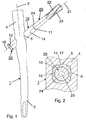
- FIGS. 1-2 and 5-7 illustrate a device for treating fractures of the femur which comprises an intramedullary nail 1, a sliding sleeve 10, a longitudinal bone fixation element 20 in the form of a helix screw and a locking means 30 in the form of a locking screw.
- the intramedullary nail 1 has a central longitudinal axis 2, a front part 3 insertable into the medullary canal of the femur, a rear part 4, and a passage 5 piercing the rear part 4 obliquely to the longitudinal axis 2 with a non-circular cross-section 6.
- the sliding sleeve 10 which can be passed through the non-circular passage 5 has a front end 11, a rear end 12, a central longitudinal bore 13, an outer lateral surface 14, an inner lateral surface 15 and a longitudinal axis 16.
- the longitudinal bone fixation element 20 in the form of a helix screw has a longitudinal axis 21, a head portion 22 with fixation means 23 in the form of a multi-thread relatively high pitch thread, which are engageable with the femoral head in use, and a, coaxially inserted into the sliding sleeve 10 shaft 24th ,
- the outer lateral surface 14 of the sliding sleeve 10 has a non-circular cross-section 17, while the inner circumferential surface 15 of the sliding sleeve 10 has a round cross-section 18.
- blocking means 30 are provided in the form of a locking screw in order to be able to selectively block the rotation of the longitudinal bone fixation element 20 in the sliding sleeve 10.
- the locking means 30 in the form of a locking screw comprise a screw head 31 of diameter D and a male screw 32 carrying screw shank 33 of diameter d, where D> d (FIG. 6).
- the external thread 32 of the screw shaft 33 corresponds to the internal thread 26 of the bore 25 of the shaft 24 of the longitudinal bone fixation element 20 and is screwed in the bore 25 until the screw head 31 strikes the rear end 12 of the sliding sleeve 10 and by further tightening the as Blocking means 30 acting locking screw a frictional connection between the longitudinal bone fixation member 20 and the sliding sleeve 10 results.
- the shaft 24 of the longitudinal bone fixation element 20 is provided with a first annular groove 28 and the inner lateral surface 15 of the sliding sleeve 10 is provided with a second annular groove 19.
- the axial mobility of the shaft 24 in the sliding sleeve 10 blocking element 40 is mounted in the form of a ring.
- the shaft 24 of the longitudinal bone fixation element 20 is rotatably but axially fixedly mounted in the sliding sleeve 10.
- the rear end 12 of the sliding sleeve 10 protrudes by a defined amount x over the free end 27 of the shaft 24 of the longitudinal bone fixation element 20 to ensure a secure adhesion when tightening the locking screw.
- this frictional connection it is possible to selectively block the rotation of the longitudinal bone fixation element 20 in the sliding sleeve 10.
- FIG. 2 shows how the circular-cylindrical shank 24 of the longitudinal bone fixation element 20 designed as a helical blade is rotatably mounted in the interior of the sliding sleeve 10, which likewise has a circular-cylindrical inner lateral surface 15.
- the substantially a square, ie non-circular cross-section 17 having outer lateral surface 14 of the sliding sleeve 10 is, however, secured in the likewise a non-circular cross-section 6 having passage 5 of the intramedullary nail 1 against rotation.
- the non-circular cross section 6 of the passage 5 is - as shown in Fig. 2 - also formed approximately square, points but additionally peripheral sections in the form of partial arcs. Thanks to this design, the intramedullary nail 1 can also be used with a conventional hip screw with a circular cylindrical shank, ie even without a sliding sleeve.
- a variant of a non-circular cross-section 6 of the passage 5 is shown, in which two small partial arcs and a larger partial arc are present. Accordingly, the non-circular cross section 17 of the outer circumferential surface 14 of the sliding sleeve 10 is formed.
- FIG. 2 results in a simpler handling, since due to the existing symmetry a wrong insertion of the hip screw is excluded.
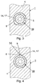
- FIG. 4 yet another variant of a non-circular cross section 6 of the passage 5 is shown, in which the cross section is substantially round, but has a longitudinal groove in which a longitudinal ridge 35 is mounted positively on the outer surface 14 of the sliding sleeve 10, so that the rotation of the two elements is secured.
- the fixation means 23 of the longitudinal bone fixation element of FIG. 5 are formed as a four-barrel helix screw, the thread having a pitch of approximately 120 mm.
- FIG. 9 shows a variant of the device according to the invention in which a nut is provided instead of a locking screw acting as a blocking means 30.
- the free end 27 of the shaft 24 of the longitudinal bone fixation element 20 instead of an internal thread on an external thread 29, which corresponds to the internal thread 34 of the nut (blocking means 30).
- Internal thread 34 and external thread 29 are formed circular cylindrical.
- the free end 27 of the shaft 24 of the longitudinal bone fixation element 20 protrudes by a defined amount x over the rear end 12 of the sliding sleeve 10 so that the nut can be screwed onto the external thread 29.
- a secure adhesion occurs during further rotation of the nut.
Landscapes
- Health & Medical Sciences (AREA)
- Orthopedic Medicine & Surgery (AREA)
- Life Sciences & Earth Sciences (AREA)
- Surgery (AREA)
- General Health & Medical Sciences (AREA)
- Animal Behavior & Ethology (AREA)
- Engineering & Computer Science (AREA)
- Biomedical Technology (AREA)
- Heart & Thoracic Surgery (AREA)
- Veterinary Medicine (AREA)
- Public Health (AREA)
- Medical Informatics (AREA)
- Neurology (AREA)
- Molecular Biology (AREA)
- Nuclear Medicine, Radiotherapy & Molecular Imaging (AREA)
- Cardiology (AREA)
- Oral & Maxillofacial Surgery (AREA)
- Transplantation (AREA)
- Vascular Medicine (AREA)
- Surgical Instruments (AREA)
- Prostheses (AREA)
- Saccharide Compounds (AREA)
- Compounds Of Unknown Constitution (AREA)
- Organic Low-Molecular-Weight Compounds And Preparation Thereof (AREA)
Description
- Die Erfindung betrifft eine Vorrichtung zur Behandlung von Frakturen des Femur gemäss dem Oberbegriff des Patentanspruchs 1 sowie einen intramedullären Marknagel zur Verwendung in einer solchen Vorrichtung gemäss dem Oberbegriff des Anspruchs 18.
- Es sind bereits Vorrichtungen bekannt, bei welchen eine Rotationssicherung des Femurkopfes mit einer einzigen Hüftschraube, d.h. einem longitudinalen Knochenfixationsmittel zu erreichen versucht wird. Aus der
EP-B 0 441 577 ist beispielsweise eine solche Vorrichtung bekannt, welche eine die Hüftschraube gleitend aufnehmende Hülse aufweist, wobei die Hülse mittels einer von proximal einführbaren Blockierschraube im Marknagel gegen Rotation gesichert werden kann. Der Schaft der Hüftschraube und die Bohrung der Hülse sind allerdings unrund ausgebildet, damit sich die Hüftschraube in der Hülse nicht drehen kann. Die Hüftschraube muss sich aber während des Einbringens in den Hüftkopf drehen können. Aus diesem Grund muss bei der Implantation zuerst die Hüftschraube eingesetzt werden und erst danach die Gleithülse. Die beiden Elemente können nicht zusammen eingeführt werden, so dass die Operation kompliziert wird. Im weiteren besteht die Gefahr, dass die Hüftschraube nach medial wandert, wenn nicht zusätzlich eine Kompressionsschraube verwendet wird. Ein weiterer Nachteil besteht darin, dass die Blockierschraube von oben (kranial) in den Marknagel eingeführt werden muss, was einen zusätzlichen Operationsschritt bedeutet. Schliesslich ist bei einer allfällig später notwendig werdenden Entfernung der Hüftschraube ein relativ grosser Eingriff notwendig, um in einem Schritt die von proximal in den Marknagel eingeschraubte Blockierschraube zu lösen, bevor die Hüftschraube entfernt werden kann. - Im weiteren ist aus der
US-A 5,454,813 LAWES ein Marknagel mit einer Hüftschraube und mit einer Gleithülse bekannt, bei welchem der Durchgang im Marknagel, das äussere und innere Profil der Gleithülse und der Schaft der Hüftschraube unrund ausgebildet sind. Die Gleithülse wirkt hier somit als Antirotationsmittel zwischen der Hüftschraube und dem Marknagel. Auch diese bekannte Vorrichtung weist die gleichen Nachteile auf wie dieEP-B 0 441 577 , d.h. eine komplizierte Operationstechnik, sowohl beim Implantieren wie auch beim Explantieren der Hüftschraube und auch die mediale Wanderung kann nur mit einem zusätzlichen Bauelement (einem Spannungseinsteller) verhindert werden. - Die obenstehende Diskussion des Standes der Technik erfolgt lediglich zur Erläuterung des Umfeldes der Erfindung und bedeutet nicht, dass der zitierte Stand der Technik zum Zeitpunkt dieser Anmeldung auch tatsächlich publiziert oder öffentlich bekannt war.
- Hier will die Erfindung Abhilfe schaffen. Der Erfindung liegt das Problem zugrunde, eine Vorrichtung zur Behandlung von Frakturen des Femur, insbesondere von proximalen Femurfrakturen zu schaffen, welche eine einfache und sichere Rotationsblockierung zwischen dem longitudinalen Knochenfixationselement (z.B. einer Hüftschraube) und dem Marknagel erlaubt, die Operationsmethode vereinfacht und verkürzt und das laterale Gleiten des longitudinalen Knochenfixationselementes nicht limitiert.
- Die Erfindung löst die gestellte Aufgabe mit einer Vorrichtung, welche die Merkmale des Anspruchs 1, sowie einem Marknagel, welcher die Merkmale des Anspruchs 18 aufweist.
- Mit der erfindungsgemässen Vorrichtung ist der Vorteil erzielbar, dass sich der vorzugsweise als Schraube oder Helixklinge ausgebildete Vorderteil des longitudinalen Knochenfixationselementes optimal in der Spongiosa des Femurkopfes verankern kann, weil der Schaft des longitudinalen Knochenfixationselement in der ihn umschliessenden Gleithülse rotativ frei beweglich bleibt und die Gleithülse mit dem darin befindlichen longitudinalen Knochenfixationselement gleichzeitig axial frei beweglich bleibt.
- Damit die klinische Handhabung dieser Kombination aus longitudinalem Knochenfixationselement + Gleithülse einfach bleibt, können die beiden Elemente vorzugsweise so vormontiert werden, dass sich das longitudinale Knochenfixationselement zwar frei in der Gleithülse drehen kann aber gegenüber dieser axial fixiert ist. Diese so vormontierte Konstruktion hat den Vorteil, dass das longitudinalen Knochenfixationselement beim Einbringen in den Femurkopf nicht speziell ausgerichtet werden muss und sich beim Einschlagen helixförmig in den Femurkopf drehen kann. Das longitudinale Knochenfixationselement ist in diesem Zeitpunkt noch nicht auf Rotation gesichert. Der Chirurg kann somit noch Rotationskorrekturen des Femurkopfes vornehmen, bevor er die Rotation des longitudinalen Knochenfixationselementes, durch das Eindrehen der Fixationsschraube von lateral her, in die Bohrung des Schaftes des longitudinalen Knochenfixationselementes blockiert.
- Eine bevorzugte Weiterbildung besteht darin, dass am freien Ende des Schaftes des longitudinalen Knochenfixationselementes eine koaxial zur Längsachse angeordnete Bohrung vorgesehen ist, welche vorzugsweise mit einem Innengewinde versehen ist.
- Bei einer speziellen Ausführungsform bestehen die Blockiermittel aus einer Feststellschraube mit einem Schraubenkopf des Durchmessers D und einem ein Aussengewinde tragenden Schraubenschaft des Durchmessers d, wobei D > d ist. Dabei korrespondiert das Aussengewinde des Schraubenschaftes mit dem Innengewinde der Bohrung des Schaftes des longitudinalen Knochenfixationselementes und ist in dessen Bohrung soweit eindrehbar, bis der Schraubenkopf auf das hintere Ende der Gleithülse auftrifft und durch weiteres Festziehen der als Blockiermittel wirkenden Feststellschraube eine kraftschlüssige Verbindung zwischen dem longitudinalen Knochenfixationselement und der Gleithülse resultiert.
- Bei einer weiteren Ausführungsform ist der Schaft des longitudinalen Knochenfixationselementes rotativ aber axial fest in der Gleithülse gelagert. Zu diesem Zweck kann der Schaft des longitudinalen Knochenfixationselementes mit einer ersten Ringnut und die innere Mantelfläche der Gleithülse mit einer zweiten Ringnut versehen sein. Im weiteren ist ein die axiale Beweglichkeit des Schaftes in der Gleithülse blockierendes Element, vorzugsweise in Form eines in die beiden Ringnuten eingreifenden Ringes vorgesehen. Statt des Ringes könnten aber auch andere blockierende Elemente (z.B. in Form eines Stiftes) verwendet werden.
- Bei einer weiteren Ausführungsform ragt das hintere Ende der Gleithülse um einen definierten Betrag x über das freie Ende des Schaftes des longitudinalen Knochenfixationselementes hervor, vorzugsweise um mindestens 0,01 mm.
- Bei einer anderen speziellen Ausführungsform ist am freien Ende des Schaftes - statt des Innengewindes - ein Aussengewinde vorgesehen. Das Blockiermittel besteht bei dieser Ausführungsform - statt der Feststellschraube - aus einer Mutter mit einem zum Aussengewinde des Schaftes korrespondierenden Innengewinde.
- Der unrunde Querschnitt des Durchgangs des intramedullären Nagels kann bei einer speziellen Ausführungsform periphere Teilabschnitte in Form von Teilkreisbögen aufweisen. Diese Kombination eines unrunden mit einem runden Querschnitt erlaubt die Verwendung dieses derart ausgestalteten Marknagels einerseits mit der erfindungsgemässen unrunden Gleithülse anderseits aber auch ohne Gleithülse, lediglich mit einem longitudinalen Knochenfixationselement (z.B. einer Hüftschraube), welches einen runden Schaft aufweist, bei dem dank dieser Gestaltung trotz des unrunden Durchgangs eine gute Führung des runden Schaftes des Knochenfixationselementes (z.B. einer Hüftschraube) resultiert. Der solcherart ausgebildete Marknagel kann somit, sofern er eine zweite Querbohrung aufweist weiterhin auch in konventioneller Weise mit zwei Knochenfixationselementen (z.B. zwei Hüftschrauben verwendet werden.
- Die Fixationsmittel des longitudinalen Knochenfixationselementes bestehen bevorzugt aus einer Helixklinge, vorzugsweise einer Doppelhelixklinge. Die Fixationsmittel können aber auch aus einem Schraubengewinde mit relativ geringer Steigung, einem Meissel, einem Nagel, einem T-Profil oder einem Doppel-T-Profil bestehen.
- Bei einer besonderen Ausführungsform ist der Kopfteil des longitudinalen Knochenfixationselementes als mehrgängiges Gewinde, vorzugsweise als viergängiges Gewinde ausgebildet. Durch diese Ausgestaltung spielt die Positionierung des Knochenfixationselementes keine Rolle mehr wie beim eingängigen Gewinde. Das Gewinde des Kopfteils kann dabei eine Steigung von mindestens 50 mm, vorzugsweise von mindestens 80 mm aufweisen. Der Vorteil dieser relativ hohen Steigung liegt im höheren Widerstand gegen Rotation des Knochenfixationselementes. Zudem zerstört das als Helixklinge ausgebildete Knochenfixationselement weniger Knochensubstanz als eine konventionelle Hüftschraube mit relativ geringer Gewindesteigung. Der Knochen wird durch die Helixflächen der Helixklinge mehr kompaktiert als geschnitten.
- Die Blockiermittel, welche in Form einer Feststellschraube oder einer Mutter realisiert sein können, sind vorzugsweise derart dimensioniert sind, dass sie bezüglich des Durchgangs des intramedullären Nagels als axialer Stop wirken. Dieser Stop vermeidet eine zu weite Migration des Knochenfixationsmittels nach medial.
- Die Erfindung und Weiterbildungen der Erfindung werden im folgenden anhand der teilweise schematischen Darstellung mehrerer Ausführungsbeispiele noch näher erläutert.
- Es zeigen:
- Fig. 1 eine Seitenansicht durch die erfindungsgemässe Vorrichtung;
- Fig. 2 einen partiellen Schnitt durch einen Marknagel im Bereich seines schrägen Durchgangs mit einem eingesetzten longitudinalen Knochenfixationselement und einer Gleithülse;
- Fig. 3 einen partiellen Schnitt durch einen modifizierten Marknagel im Bereich seines schrägen Durchgangs mit einem eingesetzten longitudinalen Knochenfixationselement und einer Gleithülse;
- Fig. 4 einen partiellen Schnitt durch eine weitere Modifikation eines Marknagels im Bereich seines schrägen Durchgangs mit einem eingesetzten longitudinalen Knochenfixationselement und einer Gleithülse;
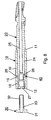
- Fig. 5 einen partiellen Längsschnitt durch die Vorrichtung nach Fig. 1;
- Fig. 6 einen vergrösserten Ausschnitt des Kreises VI in Fig. 5;
- Fig. 7 einen Schnitt längs der Linie VII-VII in Fig. 5;
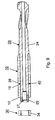
- Fig. 8 einen Längsschnitt durch eine modifizierte Gleithülse mit darin vormontierter Helix-Schraube; und
- Fig. 9 einen Längsschnitt durch eine Modifikation der Gleithülse nach Fig. 8 mit einer darin vormontierten Helix-Schraube.
- In den Fig. 1 - 2 sowie 5 - 7 ist eine Vorrichtung zur Behandlung von Frakturen des Femur dargestellt, welche einen intramedullären Nagel 1, eine Gleithülse 10, ein longitudinales Knochenfixationselement 20 in Form einer Helixschraube und ein Blockiermittel 30 in Form einer Feststellschraube umfasst.
Der intramedullären Nagel 1 besitzt eine zentrale Längsachse 2, einen in den Markkanal des Femur einführbaren Vorderteil 3, einen Hinterteil 4, sowie einen den Hinterteil 4, schräg zur Längsachse 2 durchbohrenden Durchgang 5 mit einem unrunden Querschnitt 6.
Die durch den unrunden Durchgang 5 hindurchführbare Gleithülse 10 besitzt ein vorderes Ende 11, ein hinteres Ende 12, eine zentrale Längsbohrung 13, eine äussere Mantelfläche 14, eine innere Mantelfläche 15 sowie eine Längsachse 16.
Das longitudinale Knochenfixationselement 20 in Form einer Helixschraube besitzt eine Längsachse 21, einen Kopfteil 22 mit Fixationsmitteln 23 in Form eines mehrgängigen Gewindes relativ hoher Steigung, die bei Benutzung mit dem Femurkopf in Eingriff bringbar sind, sowie einem, koaxial in die Gleithülse 10 einführbaren Schaft 24.
Die äussere Mantelfläche 14 der Gleithülse 10 weist einen unrunden Querschnitt 17 auf, während die innere Mantelfläche 15 der Gleithülse 10 einen runden Querschnitt 18 aufweist. Schliesslich sind Blockiermittel 30 in Form einer Feststellschraube vorgesehen, um die Rotation des longitudinalen Knochenfixationselementes 20 in der Gleithülse 10 wahlweise blockieren zu können. Am freien Ende 27 des Schaftes 24 des longitudinalen Knochenfixationselementes 20 ist eine koaxial zur Längsachse 21 angeordnete Bohrung 25 vorgesehen, welche mit einem Innengewinde 26 versehen ist.
Die Blockiermittel 30 in Form einer Feststellschraube weisen einen Schraubenkopf 31 des Durchmessers D und einen ein Aussengewinde 32 tragenden Schraubenschaft 33 des Durchmessers d auf, wobei D > d ist (Fig. 6). Das Aussengewinde 32 des Schraubenschaftes 33 korrespondiert mit dem Innengewinde 26 der Bohrung 25 des Schaftes 24 des longitudinalen Knochenfixationselementes 20 und ist in der Bohrung 25 soweit eindrehbar, bis der Schraubenkopf 31 auf das hintere Ende 12 der Gleithülse 10 auftrifft und durch ein weiteres Festziehen der als Blockiermittel 30 wirkenden Feststellschraube eine kraftschlüssige Verbindung zwischen dem longitudinalen Knochenfixationselement 20 und der Gleithülse 10 resultiert. - Bei einer weiteren in Fig. 8 dargestellten Ausführungsform ist der Schaft 24 des longitudinalen Knochenfixations-elementes 20 mit einer ersten Ringnut 28 und die innere Mantelfläche 15 der Gleithülse 10 mit einer zweiten Ringnut 19 versehen. In diese beiden Ringnuten 28,19 ist ein die axiale Beweglichkeit des Schaftes 24 in der Gleithülse 10 blockierendes Element 40 in Form eines Ringes gelagert. Dadurch ist der Schaft 24 des longitudinalen Knochenfixationselementes 20 rotativ aber axial fest in der Gleithülse 10 gelagert. Das hintere Ende 12 der Gleithülse 10 ragt dabei um einen definierten Betrag x über das freie Ende 27 des Schaftes 24 des longitudinalen Knochenfixationselementes 20 hervor, um einen sicheren Kraftschluss beim Anziehen der Feststellschraube zu garantieren. Durch diesen Kraftschluss ist es möglich die Rotation des longitudinalen Knochenfixationselementes 20 in der Gleithülse 10 wahlweise zu blockieren.
- In Fig. 2 ist dargestellt, wie der kreiszylindrische Schaft 24 des als Helixklinge ausgebildeten, longitudinalen Knochenfixationselementes 20 im Inneren der ebenfalls eine kreiszylindrische innere Mantelfläche 15 aufweisenden Gleithülse 10 rotativ frei gelagert ist. Die im wesentlichen einen quadratischen, d.h. unrunden Querschnitt 17 aufweisende äussere Mantelfläche 14 der Gleithülse 10 ist dagegen im ebenfalls einen unrunden Querschnitt 6 aufweisenden Durchgang 5 des Marknagels 1 gegen Rotation gesichert. Der unrunde Querschnitt 6 des Durchgangs 5 ist - wie in Fig. 2 dargestellt - ebenfalls annähernd quadratisch ausgebildet, weist aber zusätzlich periphere Teilabschnitte in Form von Teilkreisbögen auf. Dank dieser Gestaltung kann der Marknagel 1 auch mit einer konventionellen Hüftschraube mit kreiszylindrischen Schaft verwendet werden, d.h. auch ohne Gleithülse.
- In Fig. 3 ist eine Variante eines unrunden Querschnitts 6 des Durchgangs 5 dargestellt, bei welchem zwei kleine Teilkreisbögen und ein grösserer Teilkreisbogen vorhanden sind. Entsprechend ist der unrunde Querschnitt 17 der äusseren Mantelfläche 14 der Gleithülse 10 ausgebildet. Gegenüber der Ausführung nach Fig. 2 ergibt sich ein einfacheres Handling, da wegen der bestehenden Symmetrie ein falsches Einsetzen der Hüftschraube ausgeschlossen ist.
- In Fig. 4 ist noch eine weitere Variante eines unrunden Querschnitts 6 des Durchgangs 5 dargestellt, bei welchem der Querschnitt im wesentlichen zwar rund ist, aber eine Längsnut besitzt in welcher ein Längssteg 35 an der äusseren Mantelfläche 14 der Gleithülse 10 formschlüssig gelagert ist, so das die Rotation der beiden Elemente gesichert ist.
- Wie in Fig, 7 dargestellt, sind die fixationsmittel 23 des longitudinalen Knochenfixationselementes nach Fig. 5 als viergängige Helix-Schraube ausgebildet, wobei das Gewinde eine Steigung von ca. 120 mm aufweist.
- In Fig. 9 ist eine Variante der erfindungsgemässen Vorrichtung dargestellt bei welcher statt einer als Blockiermittel 30 wirkenden Feststellschraube eine Mutter vorgesehen ist. Dementsprechend weist das freie Ende 27 des Schaftes 24 des longitudinalen Knochenfixationselementes 20 statt eines Innengewindes ein Aussengewinde 29 auf, welches zum Innengewinde 34 der Mutter (Blockiermittel 30) korrespondiert. Innengewinde 34 und Aussengewinde 29 sind kreiszylindrisch ausgebildet. Das freie Ende 27 des Schaftes 24 des longitudinalen Knochenfixationselementes 20 ragt dabei um einen definierten Betrag x über das hintere Ende 12 der Gleithülse 10 hervor, damit die Mutter auf das Aussengewinde 29 aufgeschraubt werden kann. Sobald die Mutter auf das hintere Ende 12 der Gleithülse 10 stösst, entsteht ein sicherer Kraftschluss beim weiteren Verdrehen der Mutter. Durch diesen Kraftschluss ist es möglich die Rotation des longitudinalen Knochenfixationselementes 20 in der Gleithülse 10 wahlweise zu blockieren.
Claims (17)
- Vorrichtung zur Behandlung von Frakturen des Femur mitA) einem intramedullären Nagel (1) mit einer zentralen Längsachse (2), einem in den Markkanal des Femur einführbaren Vorderteil (3), einem Hinterteil (4), einen den Hinterteil (4), schräg zur Längsachse (2) durchbohrenden Durchgang (5) mit unrundem Querschnitt (6);B) einer durch den unrunden Durchgang (5) hindurchführbaren Gleithülse (10), mit einem vorderen Ende (11), einem hinteren Ende (12), einer zentralen Längsbohrung (13), einer äusseren Mantelfläche (14), einer inneren Mantelfläche (15) und einer Längsachse (16);C) einem longitudinalen Knochenfixationselement (20) mit einer Längsachse (21), einem Kopfteil (22) mit Fixationsmitteln (23), die bei Benutzung mit dem Femurkopf in Eingriff bringbar sind, sowie einem, koaxial in die Gleithülse (10) einführbaren Schaft (24); wobeiD) die äussere Mantelfläche (14) der Gleithülse (10) mindestens in einem Teilbereich einen unrunden Querschnitt (17) aufweist;
dadurch gekennzeichnet, dassE) die innere Mantelfläche (15) der Gleithülse (10) einen runden Querschnitt (18) aufweist; undF) Blockiermittel (30) vorgesehen sind, um die Rotation des longitudinalen Knochenfixationselementes (20) in der Gleithülse (10) wahlweise zu blockieren. - Vorrichtung nach Anspruch 1, dadurch gekennzeichnet, dass am freien Ende (27) des Schaftes (24) eine koaxial zur Längsachse (21) angeordnete Bohrung (25) vorgesehen ist, welche vorzugsweise mit einem Innengewinde (26) versehen ist.
- Vorrichtung nach Anspruch 1 oder 2, dadurch gekennzeichnet, dass die Blockiermittel (30) eine Feststellschraube mit einem Schraubenkopf (31) des Durchmessers D und einem ein Aussengewinde (32) tragenden Schraubenschaft (33) des Durchmessers d vorgesehen ist, wobei D > d ist.
- Vorrichtung nach Anspruch 3, dadurch gekennzeichnet, dass das Aussengewinde (32) des Schraubenschaftes (33) mit dem Innengewinde (26) der Bohrung (25) des Schaftes (24) des longitudinalen Knochenfixationselementes (20) korrespondiert und in der Bohrung (25) soweit eindrehbar ist, bis der Schraubenkopf (31) auf das hintere Ende (12) der Gleithülse (10) auftrifft und durch weiteres Festziehen der als Blockiermittel (30) wirkenden Feststellschraube eine kraftschlüssige Verbindung zwischen dem longitudinalen Knochenfixationselement (20) und der Gleithülse (10) resultiert.
- Vorrichtung nach einem der Ansprüche 1 bis 4, dadurch gekennzeichnet, dass der Schaft (24) des longitudinalen Knochenfixationselementes (20) rotativ aber axial fest in der Gleithülse (10) gelagert ist.
- Vorrichtung nach Anspruch 5, dadurch gekennzeichnet, dass der Schaft (24) des longitudinalen Knochenfixationselementes (20) mit einer ersten Ringnut (28) und die innere Mantelfläche (15) der Gleithülse (10) mit einer zweiten Ringnut (19) versehen sind und dass ein die axiale Beweglichkeit des Schaftes (24) in der Gleithülse (10) blockierendes Element (40), vorzugsweise in Form eines in die beiden Ringnuten (28,19) eingreifenden Ringes vorgesehen ist.
- Vorrichtung nach Anspruch 6, dadurch gekennzeichnet, dass das hintere Ende (12) der Gleithülse (10) um einen definierten Betrag x über das freie Ende (27) des Schaftes (24) des longitudinalen Knochenfixationselementes (20) hervorragt, vorzugsweise um mindestens x > 0,01 mm.
- Vorrichtung nach Anspruch 1, dadurch gekennzeichnet, dass am freien Ende (27) des Schaftes (24) ein Aussengewinde (29) vorgesehen ist.
- Vorrichtung nach Anspruch 8, dadurch gekennzeichnet, dass das Blockiermittel (30) eine Mutter ist mit einem zum Aussengewinde (29) des Schaftes (24) korrespondierenden Innengewinde (34).
- Vorrichtung nach einem der Ansprüche 1 bis 9, dadurch gekennzeichnet, dass der unrunde Querschnitt (6) des Durchgangs (5) periphere Teilabschnitte in Form von Teilkreisbögen aufweist.
- Vorrichtung nach einem der Ansprüche 1 bis 10, dadurch gekennzeichnet, dass die Fixationsmittel (23) des longitudinalen Knochenfixationselementes (20) eine Helixklinge, vorzugsweise eine Doppelhelixklinge sind.
- Vorrichtung nach einem der Ansprüche 1 bis 11, dadurch gekennzeichnet, dass die Fixationsmittel (23) ein Schraubengewinde, ein Meissel, ein Nagel, ein T-Profil oder ein Doppel-T-Profil sind.
- Vorrichtung nach einem der Ansprüche 1 bis 12, dadurch gekennzeichnet, dass der Kopfteil (22) des longitudinalen Knochenfixationselementes (20) als mehrgängiges Gewinde, vorzugsweise als viergängiges Gewinde ausgebildet ist.
- Vorrichtung nach einem der Ansprüche 1 bis 13, dadurch gekennzeichnet, dass das Gewinde des Kopfteils (22) eine Steigung von mindestens 50 mm, vorzugsweise mindestens 80 mm aufweist.
- Vorrichtung nach einem der Ansprüche 1 bis 14, dadurch gekennzeichnet, dass die Blockiermittel (30), welche vorzugsweise in Form einer Feststellschraube oder eine Mutter realisiert sind, derart dimensioniert sind, dass sie bezüglich des Durchgangs (5) als axialer Stop wirken.
- Vorrichtung nach einem der Ansprüche 1 bis 15, dadurch gekennzeichnet, dass das longitudinale Knochenfixationselement (20) eine Hüftschraube ist.
- Vorrichtung nach einem der Ansprüche 1 bis 15, dadurch gekennzeichnet, dass das longitudinale Knochenfixationselement (20) eine Helix-Schraube ist.
Applications Claiming Priority (1)
| Application Number | Priority Date | Filing Date | Title |
|---|---|---|---|
| PCT/CH2002/000584 WO2004039270A1 (de) | 2002-10-29 | 2002-10-29 | Vorrichtung zur behandlung von frakturen des femur |
Publications (2)
| Publication Number | Publication Date |
|---|---|
| EP1558159A1 EP1558159A1 (de) | 2005-08-03 |
| EP1558159B1 true EP1558159B1 (de) | 2007-11-14 |
Family
ID=32235038
Family Applications (1)
| Application Number | Title | Priority Date | Filing Date |
|---|---|---|---|
| EP02808064A Expired - Lifetime EP1558159B1 (de) | 2002-10-29 | 2002-10-29 | Vorrichtung zur behandlung von frakturen des femur |
Country Status (12)
| Country | Link |
|---|---|
| US (1) | US8454606B2 (de) |
| EP (1) | EP1558159B1 (de) |
| JP (1) | JP4218837B2 (de) |
| KR (1) | KR100953146B1 (de) |
| CN (1) | CN100411595C (de) |
| AT (1) | ATE378012T1 (de) |
| AU (1) | AU2002333153B2 (de) |
| BR (1) | BR0215926B1 (de) |
| CA (1) | CA2503943C (de) |
| DE (1) | DE50211236D1 (de) |
| ES (1) | ES2297058T3 (de) |
| WO (1) | WO2004039270A1 (de) |
Cited By (1)
| Publication number | Priority date | Publication date | Assignee | Title |
|---|---|---|---|---|
| US9895177B2 (en) | 2016-01-15 | 2018-02-20 | ARTHREX, GmbH | Bone fixation device for treatment of femoral fractures |
Families Citing this family (53)
| Publication number | Priority date | Publication date | Assignee | Title |
|---|---|---|---|---|
| US8070786B2 (en) * | 1993-01-21 | 2011-12-06 | Acumed Llc | System for fusing joints |
| US9161793B2 (en) | 1993-01-21 | 2015-10-20 | Acumed Llc | Axial tension screw |
| US7179260B2 (en) | 2003-09-29 | 2007-02-20 | Smith & Nephew, Inc. | Bone plates and bone plate assemblies |
| US7455673B2 (en) * | 2003-07-08 | 2008-11-25 | Yechiel Gotfried | Intramedullary nail system and method for fixation of a fractured bone |
| US7780667B2 (en) * | 2003-09-08 | 2010-08-24 | Smith & Nephew, Inc. | Orthopaedic plate and screw assembly |
| US7799030B2 (en) * | 2003-09-08 | 2010-09-21 | Smith & Nephew, Inc. | Orthopaedic plate and screw assembly |
| US20050055024A1 (en) | 2003-09-08 | 2005-03-10 | James Anthony H. | Orthopaedic implant and screw assembly |
| NZ545901A (en) * | 2003-09-18 | 2007-11-30 | Synthes Gmbh | Device for treating femoral fractures comprising means for releasable form-locking of the rotation between the longitudinal bone fixing element and the intramedullary pin |
| US20070049940A1 (en) * | 2005-08-31 | 2007-03-01 | Wallace Matthew S | Intramedullary nail assembly with fixed securement and associated method |
| US20070049938A1 (en) * | 2005-08-31 | 2007-03-01 | Wallace Matthew S | Intramedullary nail assembly with locking component, locking component and nail for use therewith |
| EP1945120A1 (de) * | 2005-09-28 | 2008-07-23 | Smith and Nephew, Inc. | Instrument zur reposition von frakturen, insbesondere des oberschenkelhalses |
| US20070155271A1 (en) * | 2005-12-30 | 2007-07-05 | Touzov Igor V | Heat conductive textile and method producing thereof |
| CA2648490C (en) * | 2006-04-06 | 2014-09-09 | Halifax Biomedical Inc. | Intramedullary rod with vent |
| CN101426442B (zh) | 2006-04-21 | 2013-05-29 | 新特斯有限责任公司 | 髋关节螺旋植入物 |
| CA2671523C (en) | 2006-12-07 | 2013-02-12 | Anatol Podolsky | Method and apparatus for total hip replacement |
| US8974540B2 (en) | 2006-12-07 | 2015-03-10 | Ihip Surgical, Llc | Method and apparatus for attachment in a modular hip replacement or fracture fixation device |
| US8579985B2 (en) * | 2006-12-07 | 2013-11-12 | Ihip Surgical, Llc | Method and apparatus for hip replacement |
| US7918853B2 (en) | 2007-03-20 | 2011-04-05 | Smith & Nephew, Inc. | Orthopaedic plate and screw assembly |
| US8177786B2 (en) * | 2007-03-30 | 2012-05-15 | Depuy Products, Inc. | Orthopaedic trauma hip screw assembly and associated method |
| CA2686932A1 (en) | 2007-05-25 | 2008-12-04 | Zimmer Gmbh | Reinforced intramedullary nail |
| GB2460909B (en) * | 2008-01-28 | 2010-09-08 | Mark B Sommers | Bone Nail |
| JP5158860B2 (ja) * | 2008-03-05 | 2013-03-06 | ナカシマプロペラ株式会社 | 大腿骨骨折治療用インプラント |
| US8668695B2 (en) | 2008-10-15 | 2014-03-11 | Zimmer Gmbh | Intramedullary nail |
| US9295504B2 (en) | 2009-03-31 | 2016-03-29 | Biomet C.V. | Intramedullary nail with locking key |
| AU2010266297B2 (en) | 2009-06-30 | 2016-02-25 | Smith & Nephew, Inc. | Orthopaedic implant and fastener assembly |
| US8449544B2 (en) | 2009-06-30 | 2013-05-28 | Smith & Nephew, Inc. | Orthopaedic implant and fastener assembly |
| US8808293B2 (en) * | 2011-01-21 | 2014-08-19 | DePuy Synthes Products, LLC | Trochanteric femoral nail augmentable |
| CN103079380A (zh) * | 2011-10-26 | 2013-05-01 | 鸿富锦精密工业(深圳)有限公司 | 风扇模组及具有该风扇模组的机柜 |
| ES2548045T3 (es) * | 2012-10-01 | 2015-10-13 | Stryker Trauma Gmbh | Clavo intramedular y sistema de implante que comprende dicho clavo |
| CA2928274C (en) * | 2013-10-22 | 2022-10-18 | General Surgical Company (India) Pvt Limited | A device for bone support with improved rotational stability |
| JP5770394B1 (ja) * | 2013-11-07 | 2015-08-26 | 株式会社フォーエス | 大腿骨近位部骨折の骨接合装置 |
| WO2015172842A1 (en) * | 2014-05-16 | 2015-11-19 | Stryker Trauma Gmbh | Orthopedic locking screw for an orthopedic fastening system and method of securing an orthopedic locking screw |
| US10045803B2 (en) | 2014-07-03 | 2018-08-14 | Mayo Foundation For Medical Education And Research | Sacroiliac joint fusion screw and method |
| EP3297555B1 (de) * | 2015-05-22 | 2019-06-26 | Stryker European Holdings I, LLC | Implantatsystem zur knochenfixierung |
| TWI589263B (zh) * | 2015-06-04 | 2017-07-01 | 愛派司生技股份有限公司 | 一種用於股骨骨折之固定系統 |
| US11076897B2 (en) | 2015-11-18 | 2021-08-03 | Stryker European Holdings I, Llc | Orthopedic locking screw for an orthopedic fastening system |
| CN105877830B (zh) * | 2015-12-14 | 2018-07-06 | 重庆医科大学附属永川医院 | 一种用于大段骨缺损的骨搬运装置 |
| CN105476702B (zh) * | 2015-12-14 | 2018-03-09 | 重庆医科大学附属永川医院 | 一种用于肱骨大段骨缺损的骨搬运装置 |
| CN105476701B (zh) * | 2015-12-14 | 2018-03-09 | 重庆医科大学附属永川医院 | 一种用于股骨大段骨缺损的骨搬运装置 |
| CN106859757B (zh) * | 2015-12-14 | 2018-07-06 | 重庆医科大学附属永川医院 | 一种用于胫骨大段骨缺损的骨搬运装置 |
| US10751071B2 (en) | 2016-04-25 | 2020-08-25 | Imds Llc | Joint fusion instrumentation and methods |
| US10413332B2 (en) | 2016-04-25 | 2019-09-17 | Imds Llc | Joint fusion implant and methods |
| US11083503B2 (en) | 2016-09-22 | 2021-08-10 | Globus Medical, Inc. | Systems and methods for intramedullary nail implantation |
| US10492803B2 (en) | 2016-09-22 | 2019-12-03 | Globus Medical, Inc. | Systems and methods for intramedullary nail implantation |
| EP3735193A1 (de) | 2018-01-03 | 2020-11-11 | GLW, Inc. | Hybride kanülierte orthopädische schrauben |
| WO2019140438A1 (en) | 2018-01-15 | 2019-07-18 | Sands Steven Saam | Hybrid intramedullary rods |
| CN108210047B (zh) * | 2018-03-27 | 2025-02-18 | 孙立山 | 股骨近端骨折髓内固定装置 |
| WO2020191009A1 (en) | 2019-03-18 | 2020-09-24 | Lee Thomas Hoon | Hybrid bone plate |
| US11633219B2 (en) | 2019-06-26 | 2023-04-25 | Globus Medical, Inc. | Fenestrated pedicle nail |
| US11553950B2 (en) * | 2020-10-27 | 2023-01-17 | Spinal Generations, Llc | Lag screw systems and nail systems and methods incorporating the same |
| US12193717B2 (en) | 2021-04-09 | 2025-01-14 | Glw, Inc. | Hybrid bone plates and related systems and methods |
| CN113229915B (zh) * | 2021-04-21 | 2022-12-13 | 天津市金兴达实业有限公司 | 髓内针 |
| CN114259287B (zh) * | 2021-12-24 | 2025-08-08 | 北京理贝尔生物工程研究所有限公司 | 髓内锁钉组件 |
Family Cites Families (15)
| Publication number | Priority date | Publication date | Assignee | Title |
|---|---|---|---|---|
| DE1071285B (de) * | 1959-12-17 | Verbindungsvorrichtung für gelenknahe Knochenbrüche | ||
| US4432358A (en) * | 1982-01-22 | 1984-02-21 | Fixel Irving E | Compression hip screw apparatus |
| US5032125A (en) * | 1990-02-06 | 1991-07-16 | Smith & Nephew Richards Inc. | Intramedullary hip screw |
| GB9113578D0 (en) | 1991-06-24 | 1991-08-14 | Howmedica | Intramedullary intertrochanteric fracture fixation appliance |
| FR2698261B1 (fr) * | 1992-11-24 | 1995-03-17 | Lacaffiniere Jean Yves De | Dispositif de guidage d'une double vis du col du fémur pour clou trochantéro-diaphysaire verrouillé. |
| US5324292A (en) | 1993-02-10 | 1994-06-28 | Zimmer, Inc. | Fracture fixation assembly with selectively removable protrusion |
| CA2260271C (en) * | 1996-07-31 | 2005-03-22 | Synthes Usa, Llc | Device for attaching fractured hip-joint heads |
| US5741256A (en) * | 1997-01-13 | 1998-04-21 | Synthes (U.S.A.) | Helical osteosynthetic implant |
| DE19723339C2 (de) * | 1997-06-04 | 1999-05-06 | Aesculap Ag & Co Kg | Implantat |
| CN2316927Y (zh) * | 1997-11-21 | 1999-05-05 | 海城市正骨医院 | 髋关节内支撑器 |
| US6648889B2 (en) * | 2001-04-24 | 2003-11-18 | Dale G. Bramlet | Intramedullary hip nail with bifurcated lock |
| US6835197B2 (en) * | 2001-10-17 | 2004-12-28 | Christoph Andreas Roth | Bone fixation system |
| US20040044345A1 (en) * | 2002-08-28 | 2004-03-04 | Demoss Richard Marshal | Shallow penetration bone screw |
| US20060155281A1 (en) * | 2002-10-01 | 2006-07-13 | Thomas Kaup | Device for fixing bones |
| US7455673B2 (en) * | 2003-07-08 | 2008-11-25 | Yechiel Gotfried | Intramedullary nail system and method for fixation of a fractured bone |
-
2002
- 2002-10-29 KR KR1020057007039A patent/KR100953146B1/ko not_active Expired - Fee Related
- 2002-10-29 BR BRPI0215926-0A patent/BR0215926B1/pt not_active IP Right Cessation
- 2002-10-29 US US10/532,909 patent/US8454606B2/en not_active Expired - Fee Related
- 2002-10-29 AT AT02808064T patent/ATE378012T1/de active
- 2002-10-29 EP EP02808064A patent/EP1558159B1/de not_active Expired - Lifetime
- 2002-10-29 DE DE50211236T patent/DE50211236D1/de not_active Expired - Lifetime
- 2002-10-29 AU AU2002333153A patent/AU2002333153B2/en not_active Ceased
- 2002-10-29 WO PCT/CH2002/000584 patent/WO2004039270A1/de not_active Ceased
- 2002-10-29 JP JP2004547329A patent/JP4218837B2/ja not_active Expired - Fee Related
- 2002-10-29 CA CA2503943A patent/CA2503943C/en not_active Expired - Fee Related
- 2002-10-29 CN CNB028298187A patent/CN100411595C/zh not_active Expired - Fee Related
- 2002-10-29 ES ES02808064T patent/ES2297058T3/es not_active Expired - Lifetime
Cited By (1)
| Publication number | Priority date | Publication date | Assignee | Title |
|---|---|---|---|---|
| US9895177B2 (en) | 2016-01-15 | 2018-02-20 | ARTHREX, GmbH | Bone fixation device for treatment of femoral fractures |
Also Published As
| Publication number | Publication date |
|---|---|
| AU2002333153A1 (en) | 2004-05-25 |
| CN1694650A (zh) | 2005-11-09 |
| CN100411595C (zh) | 2008-08-20 |
| US20060149247A1 (en) | 2006-07-06 |
| DE50211236D1 (de) | 2007-12-27 |
| KR20050083809A (ko) | 2005-08-26 |
| BR0215926A (pt) | 2005-08-09 |
| WO2004039270A1 (de) | 2004-05-13 |
| EP1558159A1 (de) | 2005-08-03 |
| CA2503943C (en) | 2010-12-14 |
| BR0215926B1 (pt) | 2012-05-02 |
| KR100953146B1 (ko) | 2010-04-16 |
| ATE378012T1 (de) | 2007-11-15 |
| CA2503943A1 (en) | 2004-05-13 |
| ES2297058T3 (es) | 2008-05-01 |
| JP2006504456A (ja) | 2006-02-09 |
| AU2002333153B2 (en) | 2006-09-28 |
| US8454606B2 (en) | 2013-06-04 |
| JP4218837B2 (ja) | 2009-02-04 |
Similar Documents
| Publication | Publication Date | Title |
|---|---|---|
| EP1558159B1 (de) | Vorrichtung zur behandlung von frakturen des femur | |
| EP1663036B1 (de) | Vorrichtung zur behandlung von frakturen des femur | |
| DE10246386B4 (de) | Knochenschraube, Knochenfixationseinrichtung und Halteelement | |
| EP1761182B1 (de) | Chirurgischer nagel | |
| EP1601297B1 (de) | Verriegelungsschraube für marknagel | |
| EP1681024B1 (de) | Knochenverankerungselement | |
| EP1430846B1 (de) | Knochenschraube für die Wirbelsäulen- oder Knochenchirurgie | |
| EP1631205B1 (de) | Chirurgischer nagel | |
| EP1131008B1 (de) | Markraumnagel zur operativen behandlung von unterarmfrakturen | |
| EP2317949B1 (de) | Knochenschraubenset | |
| WO1999062417A1 (de) | Chirurgische blindniete mit schliesselement | |
| EP1758513B1 (de) | Chirurgischer nagel | |
| DE2705154A1 (de) | Knochenmarknagel und zielgeraet zu seiner verankerung im markkanal | |
| DE2906068C2 (de) | Einrichtung zur Befestigung von Knochenstücken | |
| DE19852945B4 (de) | Knochennagel für die intramedulläre Kompressionsnagelung von Femurfrakturen | |
| WO2004000144A1 (de) | Knochenschraube mit tangentialer schneidkante | |
| WO2007147688A1 (de) | Femurkopf-implantat | |
| DE4418974C2 (de) | Bohrdraht zum Stabilisieren von Knochenbruchfragmenten sowie Bohraufsatz und Spannschraubenzieher | |
| DE9401916U1 (de) | Multifunktioneller Kulissen-Marknagel | |
| WO2007023101A1 (de) | Proximaler femurnagel | |
| DE19504115A1 (de) | Vorrichtung zur Behandlung von Schenkelhalsfrakturen | |
| WO2016083355A1 (de) | Befestigungselement |
Legal Events
| Date | Code | Title | Description |
|---|---|---|---|
| REG | Reference to a national code |
Ref country code: SE Ref legal event code: TRGR |
|
| PUAI | Public reference made under article 153(3) epc to a published international application that has entered the european phase |
Free format text: ORIGINAL CODE: 0009012 |
|
| 17P | Request for examination filed |
Effective date: 20050324 |
|
| AK | Designated contracting states |
Kind code of ref document: A1 Designated state(s): AT BE BG CH CY CZ DE DK EE ES FI FR GB GR IE IT LI LU MC NL PT SE SK TR |
|
| AX | Request for extension of the european patent |
Extension state: AL LT LV MK RO SI |
|
| RAP1 | Party data changed (applicant data changed or rights of an application transferred) |
Owner name: SYNTHES GMBH |
|
| RAP1 | Party data changed (applicant data changed or rights of an application transferred) |
Owner name: SYNTHES GMBH |
|
| DAX | Request for extension of the european patent (deleted) | ||
| RIN1 | Information on inventor provided before grant (corrected) |
Inventor name: BARRIOS, ELENA Inventor name: HATTLER, ERIC Inventor name: FRIGG, ROBERT Inventor name: WIDMER, WALTER |
|
| GRAP | Despatch of communication of intention to grant a patent |
Free format text: ORIGINAL CODE: EPIDOSNIGR1 |
|
| GRAS | Grant fee paid |
Free format text: ORIGINAL CODE: EPIDOSNIGR3 |
|
| GRAA | (expected) grant |
Free format text: ORIGINAL CODE: 0009210 |
|
| AK | Designated contracting states |
Kind code of ref document: B1 Designated state(s): AT BE BG CH CY CZ DE DK EE ES FI FR GB GR IE IT LI LU MC NL PT SE SK TR |
|
| REG | Reference to a national code |
Ref country code: GB Ref legal event code: FG4D Free format text: NOT ENGLISH |
|
| RIN1 | Information on inventor provided before grant (corrected) |
Inventor name: FRIGG, ROBERT Inventor name: HATTLER, ERIC Inventor name: WIDMER, WALTER Inventor name: BARRIOS, ELENA |
|
| REG | Reference to a national code |
Ref country code: CH Ref legal event code: EP |
|
| REG | Reference to a national code |
Ref country code: IE Ref legal event code: FG4D Free format text: LANGUAGE OF EP DOCUMENT: GERMAN |
|
| REG | Reference to a national code |
Ref country code: CH Ref legal event code: NV Representative=s name: DR. LUSUARDI AG |
|
| REF | Corresponds to: |
Ref document number: 50211236 Country of ref document: DE Date of ref document: 20071227 Kind code of ref document: P |
|
| GBT | Gb: translation of ep patent filed (gb section 77(6)(a)/1977) |
Effective date: 20071206 |
|
| ET | Fr: translation filed | ||
| PG25 | Lapsed in a contracting state [announced via postgrant information from national office to epo] |
Ref country code: NL Free format text: LAPSE BECAUSE OF FAILURE TO SUBMIT A TRANSLATION OF THE DESCRIPTION OR TO PAY THE FEE WITHIN THE PRESCRIBED TIME-LIMIT Effective date: 20071114 |
|
| NLV1 | Nl: lapsed or annulled due to failure to fulfill the requirements of art. 29p and 29m of the patents act | ||
| REG | Reference to a national code |
Ref country code: ES Ref legal event code: FG2A Ref document number: 2297058 Country of ref document: ES Kind code of ref document: T3 |
|
| PG25 | Lapsed in a contracting state [announced via postgrant information from national office to epo] |
Ref country code: FI Free format text: LAPSE BECAUSE OF FAILURE TO SUBMIT A TRANSLATION OF THE DESCRIPTION OR TO PAY THE FEE WITHIN THE PRESCRIBED TIME-LIMIT Effective date: 20071114 Ref country code: BG Free format text: LAPSE BECAUSE OF FAILURE TO SUBMIT A TRANSLATION OF THE DESCRIPTION OR TO PAY THE FEE WITHIN THE PRESCRIBED TIME-LIMIT Effective date: 20080214 |
|
| PG25 | Lapsed in a contracting state [announced via postgrant information from national office to epo] |
Ref country code: DK Free format text: LAPSE BECAUSE OF FAILURE TO SUBMIT A TRANSLATION OF THE DESCRIPTION OR TO PAY THE FEE WITHIN THE PRESCRIBED TIME-LIMIT Effective date: 20071114 Ref country code: CZ Free format text: LAPSE BECAUSE OF FAILURE TO SUBMIT A TRANSLATION OF THE DESCRIPTION OR TO PAY THE FEE WITHIN THE PRESCRIBED TIME-LIMIT Effective date: 20071114 |
|
| PG25 | Lapsed in a contracting state [announced via postgrant information from national office to epo] |
Ref country code: SK Free format text: LAPSE BECAUSE OF FAILURE TO SUBMIT A TRANSLATION OF THE DESCRIPTION OR TO PAY THE FEE WITHIN THE PRESCRIBED TIME-LIMIT Effective date: 20071114 |
|
| PLBE | No opposition filed within time limit |
Free format text: ORIGINAL CODE: 0009261 |
|
| STAA | Information on the status of an ep patent application or granted ep patent |
Free format text: STATUS: NO OPPOSITION FILED WITHIN TIME LIMIT |
|
| PG25 | Lapsed in a contracting state [announced via postgrant information from national office to epo] |
Ref country code: PT Free format text: LAPSE BECAUSE OF FAILURE TO SUBMIT A TRANSLATION OF THE DESCRIPTION OR TO PAY THE FEE WITHIN THE PRESCRIBED TIME-LIMIT Effective date: 20080414 |
|
| REG | Reference to a national code |
Ref country code: IE Ref legal event code: FD4D |
|
| 26N | No opposition filed |
Effective date: 20080815 |
|
| PG25 | Lapsed in a contracting state [announced via postgrant information from national office to epo] |
Ref country code: IE Free format text: LAPSE BECAUSE OF FAILURE TO SUBMIT A TRANSLATION OF THE DESCRIPTION OR TO PAY THE FEE WITHIN THE PRESCRIBED TIME-LIMIT Effective date: 20071114 |
|
| PG25 | Lapsed in a contracting state [announced via postgrant information from national office to epo] |
Ref country code: GR Free format text: LAPSE BECAUSE OF FAILURE TO SUBMIT A TRANSLATION OF THE DESCRIPTION OR TO PAY THE FEE WITHIN THE PRESCRIBED TIME-LIMIT Effective date: 20080215 |
|
| BERE | Be: lapsed |
Owner name: SYNTHES GMBH Effective date: 20081031 |
|
| PG25 | Lapsed in a contracting state [announced via postgrant information from national office to epo] |
Ref country code: EE Free format text: LAPSE BECAUSE OF FAILURE TO SUBMIT A TRANSLATION OF THE DESCRIPTION OR TO PAY THE FEE WITHIN THE PRESCRIBED TIME-LIMIT Effective date: 20071114 |
|
| PG25 | Lapsed in a contracting state [announced via postgrant information from national office to epo] |
Ref country code: MC Free format text: LAPSE BECAUSE OF NON-PAYMENT OF DUE FEES Effective date: 20081031 |
|
| PG25 | Lapsed in a contracting state [announced via postgrant information from national office to epo] |
Ref country code: CY Free format text: LAPSE BECAUSE OF FAILURE TO SUBMIT A TRANSLATION OF THE DESCRIPTION OR TO PAY THE FEE WITHIN THE PRESCRIBED TIME-LIMIT Effective date: 20071114 |
|
| PG25 | Lapsed in a contracting state [announced via postgrant information from national office to epo] |
Ref country code: BE Free format text: LAPSE BECAUSE OF NON-PAYMENT OF DUE FEES Effective date: 20081031 |
|
| PGFP | Annual fee paid to national office [announced via postgrant information from national office to epo] |
Ref country code: ES Payment date: 20091117 Year of fee payment: 8 Ref country code: SE Payment date: 20091007 Year of fee payment: 8 |
|
| PG25 | Lapsed in a contracting state [announced via postgrant information from national office to epo] |
Ref country code: LU Free format text: LAPSE BECAUSE OF NON-PAYMENT OF DUE FEES Effective date: 20081029 |
|
| PG25 | Lapsed in a contracting state [announced via postgrant information from national office to epo] |
Ref country code: TR Free format text: LAPSE BECAUSE OF FAILURE TO SUBMIT A TRANSLATION OF THE DESCRIPTION OR TO PAY THE FEE WITHIN THE PRESCRIBED TIME-LIMIT Effective date: 20071114 |
|
| PG25 | Lapsed in a contracting state [announced via postgrant information from national office to epo] |
Ref country code: SE Free format text: LAPSE BECAUSE OF NON-PAYMENT OF DUE FEES Effective date: 20101030 |
|
| REG | Reference to a national code |
Ref country code: ES Ref legal event code: FD2A Effective date: 20111118 |
|
| PG25 | Lapsed in a contracting state [announced via postgrant information from national office to epo] |
Ref country code: ES Free format text: LAPSE BECAUSE OF NON-PAYMENT OF DUE FEES Effective date: 20101030 |
|
| PGFP | Annual fee paid to national office [announced via postgrant information from national office to epo] |
Ref country code: AT Payment date: 20150928 Year of fee payment: 14 |
|
| REG | Reference to a national code |
Ref country code: FR Ref legal event code: PLFP Year of fee payment: 15 |
|
| REG | Reference to a national code |
Ref country code: AT Ref legal event code: MM01 Ref document number: 378012 Country of ref document: AT Kind code of ref document: T Effective date: 20161029 |
|
| PG25 | Lapsed in a contracting state [announced via postgrant information from national office to epo] |
Ref country code: AT Free format text: LAPSE BECAUSE OF NON-PAYMENT OF DUE FEES Effective date: 20161029 |
|
| REG | Reference to a national code |
Ref country code: FR Ref legal event code: PLFP Year of fee payment: 16 |
|
| REG | Reference to a national code |
Ref country code: FR Ref legal event code: PLFP Year of fee payment: 17 |
|
| PGFP | Annual fee paid to national office [announced via postgrant information from national office to epo] |
Ref country code: FR Payment date: 20190913 Year of fee payment: 18 |
|
| PGFP | Annual fee paid to national office [announced via postgrant information from national office to epo] |
Ref country code: DE Payment date: 20191015 Year of fee payment: 18 |
|
| PGFP | Annual fee paid to national office [announced via postgrant information from national office to epo] |
Ref country code: IT Payment date: 20191009 Year of fee payment: 18 |
|
| PGFP | Annual fee paid to national office [announced via postgrant information from national office to epo] |
Ref country code: CH Payment date: 20191015 Year of fee payment: 18 |
|
| PGFP | Annual fee paid to national office [announced via postgrant information from national office to epo] |
Ref country code: GB Payment date: 20191024 Year of fee payment: 18 |
|
| REG | Reference to a national code |
Ref country code: DE Ref legal event code: R119 Ref document number: 50211236 Country of ref document: DE |
|
| REG | Reference to a national code |
Ref country code: CH Ref legal event code: PL |
|
| GBPC | Gb: european patent ceased through non-payment of renewal fee |
Effective date: 20201029 |
|
| PG25 | Lapsed in a contracting state [announced via postgrant information from national office to epo] |
Ref country code: DE Free format text: LAPSE BECAUSE OF NON-PAYMENT OF DUE FEES Effective date: 20210501 Ref country code: FR Free format text: LAPSE BECAUSE OF NON-PAYMENT OF DUE FEES Effective date: 20201031 |
|
| PG25 | Lapsed in a contracting state [announced via postgrant information from national office to epo] |
Ref country code: GB Free format text: LAPSE BECAUSE OF NON-PAYMENT OF DUE FEES Effective date: 20201029 Ref country code: LI Free format text: LAPSE BECAUSE OF NON-PAYMENT OF DUE FEES Effective date: 20201031 Ref country code: CH Free format text: LAPSE BECAUSE OF NON-PAYMENT OF DUE FEES Effective date: 20201031 |
|
| PG25 | Lapsed in a contracting state [announced via postgrant information from national office to epo] |
Ref country code: IT Free format text: LAPSE BECAUSE OF NON-PAYMENT OF DUE FEES Effective date: 20201029 |