EP1557893B1 - Brennstoffzelle - Google Patents
Brennstoffzelle Download PDFInfo
- Publication number
- EP1557893B1 EP1557893B1 EP03758972A EP03758972A EP1557893B1 EP 1557893 B1 EP1557893 B1 EP 1557893B1 EP 03758972 A EP03758972 A EP 03758972A EP 03758972 A EP03758972 A EP 03758972A EP 1557893 B1 EP1557893 B1 EP 1557893B1
- Authority
- EP
- European Patent Office
- Prior art keywords
- coolant
- passage
- oxygen
- containing gas
- buffer
- Prior art date
- Legal status (The legal status is an assumption and is not a legal conclusion. Google has not performed a legal analysis and makes no representation as to the accuracy of the status listed.)
- Expired - Lifetime
Links
- 239000000446 fuel Substances 0.000 title claims description 70
- 239000000872 buffer Substances 0.000 claims abstract description 217
- 239000002826 coolant Substances 0.000 claims abstract description 196
- 229910052751 metal Inorganic materials 0.000 claims abstract description 153
- 239000002184 metal Substances 0.000 claims abstract description 153
- 239000007789 gas Substances 0.000 claims description 143
- QVGXLLKOCUKJST-UHFFFAOYSA-N atomic oxygen Chemical compound [O] QVGXLLKOCUKJST-UHFFFAOYSA-N 0.000 claims description 125
- 239000001301 oxygen Substances 0.000 claims description 125
- 229910052760 oxygen Inorganic materials 0.000 claims description 125
- 239000002737 fuel gas Substances 0.000 claims description 114
- 239000003792 electrolyte Substances 0.000 claims description 11
- 239000000376 reactant Substances 0.000 claims description 7
- 230000007423 decrease Effects 0.000 claims 1
- 239000012528 membrane Substances 0.000 description 25
- 238000010248 power generation Methods 0.000 description 11
- 239000001257 hydrogen Substances 0.000 description 8
- 229910052739 hydrogen Inorganic materials 0.000 description 8
- UFHFLCQGNIYNRP-UHFFFAOYSA-N Hydrogen Chemical compound [H][H] UFHFLCQGNIYNRP-UHFFFAOYSA-N 0.000 description 6
- 239000003054 catalyst Substances 0.000 description 6
- 230000000052 comparative effect Effects 0.000 description 6
- 239000007787 solid Substances 0.000 description 6
- OKTJSMMVPCPJKN-UHFFFAOYSA-N Carbon Chemical compound [C] OKTJSMMVPCPJKN-UHFFFAOYSA-N 0.000 description 5
- 229910052799 carbon Inorganic materials 0.000 description 5
- 239000005518 polymer electrolyte Substances 0.000 description 5
- XLYOFNOQVPJJNP-UHFFFAOYSA-N water Substances O XLYOFNOQVPJJNP-UHFFFAOYSA-N 0.000 description 5
- WYTGDNHDOZPMIW-RCBQFDQVSA-N alstonine Natural products C1=CC2=C3C=CC=CC3=NC2=C2N1C[C@H]1[C@H](C)OC=C(C(=O)OC)[C@H]1C2 WYTGDNHDOZPMIW-RCBQFDQVSA-N 0.000 description 4
- LYCAIKOWRPUZTN-UHFFFAOYSA-N Ethylene glycol Chemical compound OCCO LYCAIKOWRPUZTN-UHFFFAOYSA-N 0.000 description 3
- 229910052774 Proactinium Inorganic materials 0.000 description 3
- 238000007599 discharging Methods 0.000 description 3
- -1 hydrogen ions Chemical class 0.000 description 3
- 230000001590 oxidative effect Effects 0.000 description 3
- 239000003575 carbonaceous material Substances 0.000 description 2
- 239000000470 constituent Substances 0.000 description 2
- 238000009792 diffusion process Methods 0.000 description 2
- 229910052745 lead Inorganic materials 0.000 description 2
- 239000002245 particle Substances 0.000 description 2
- 229920000642 polymer Polymers 0.000 description 2
- 229910001260 Pt alloy Inorganic materials 0.000 description 1
- 238000006243 chemical reaction Methods 0.000 description 1
- 238000012790 confirmation Methods 0.000 description 1
- 230000005611 electricity Effects 0.000 description 1
- 238000003487 electrochemical reaction Methods 0.000 description 1
- UQSQSQZYBQSBJZ-UHFFFAOYSA-N fluorosulfonic acid Chemical compound OS(F)(=O)=O UQSQSQZYBQSBJZ-UHFFFAOYSA-N 0.000 description 1
- 239000003014 ion exchange membrane Substances 0.000 description 1
- 229910052763 palladium Inorganic materials 0.000 description 1
Images


Classifications
-
- H—ELECTRICITY
- H01—ELECTRIC ELEMENTS
- H01M—PROCESSES OR MEANS, e.g. BATTERIES, FOR THE DIRECT CONVERSION OF CHEMICAL ENERGY INTO ELECTRICAL ENERGY
- H01M8/00—Fuel cells; Manufacture thereof
- H01M8/02—Details
- H01M8/0202—Collectors; Separators, e.g. bipolar separators; Interconnectors
- H01M8/0247—Collectors; Separators, e.g. bipolar separators; Interconnectors characterised by the form
-
- H—ELECTRICITY
- H01—ELECTRIC ELEMENTS
- H01M—PROCESSES OR MEANS, e.g. BATTERIES, FOR THE DIRECT CONVERSION OF CHEMICAL ENERGY INTO ELECTRICAL ENERGY
- H01M8/00—Fuel cells; Manufacture thereof
- H01M8/02—Details
- H01M8/0202—Collectors; Separators, e.g. bipolar separators; Interconnectors
- H01M8/0258—Collectors; Separators, e.g. bipolar separators; Interconnectors characterised by the configuration of channels, e.g. by the flow field of the reactant or coolant
- H01M8/0263—Collectors; Separators, e.g. bipolar separators; Interconnectors characterised by the configuration of channels, e.g. by the flow field of the reactant or coolant having meandering or serpentine paths
-
- H—ELECTRICITY
- H01—ELECTRIC ELEMENTS
- H01M—PROCESSES OR MEANS, e.g. BATTERIES, FOR THE DIRECT CONVERSION OF CHEMICAL ENERGY INTO ELECTRICAL ENERGY
- H01M8/00—Fuel cells; Manufacture thereof
- H01M8/02—Details
- H01M8/0202—Collectors; Separators, e.g. bipolar separators; Interconnectors
- H01M8/0267—Collectors; Separators, e.g. bipolar separators; Interconnectors having heating or cooling means, e.g. heaters or coolant flow channels
-
- H—ELECTRICITY
- H01—ELECTRIC ELEMENTS
- H01M—PROCESSES OR MEANS, e.g. BATTERIES, FOR THE DIRECT CONVERSION OF CHEMICAL ENERGY INTO ELECTRICAL ENERGY
- H01M8/00—Fuel cells; Manufacture thereof
- H01M8/24—Grouping of fuel cells, e.g. stacking of fuel cells
- H01M8/241—Grouping of fuel cells, e.g. stacking of fuel cells with solid or matrix-supported electrolytes
-
- H—ELECTRICITY
- H01—ELECTRIC ELEMENTS
- H01M—PROCESSES OR MEANS, e.g. BATTERIES, FOR THE DIRECT CONVERSION OF CHEMICAL ENERGY INTO ELECTRICAL ENERGY
- H01M8/00—Fuel cells; Manufacture thereof
- H01M8/24—Grouping of fuel cells, e.g. stacking of fuel cells
- H01M8/2457—Grouping of fuel cells, e.g. stacking of fuel cells with both reactants being gaseous or vaporised
-
- H—ELECTRICITY
- H01—ELECTRIC ELEMENTS
- H01M—PROCESSES OR MEANS, e.g. BATTERIES, FOR THE DIRECT CONVERSION OF CHEMICAL ENERGY INTO ELECTRICAL ENERGY
- H01M8/00—Fuel cells; Manufacture thereof
- H01M8/24—Grouping of fuel cells, e.g. stacking of fuel cells
- H01M8/2465—Details of groupings of fuel cells
- H01M8/2483—Details of groupings of fuel cells characterised by internal manifolds
-
- H—ELECTRICITY
- H01—ELECTRIC ELEMENTS
- H01M—PROCESSES OR MEANS, e.g. BATTERIES, FOR THE DIRECT CONVERSION OF CHEMICAL ENERGY INTO ELECTRICAL ENERGY
- H01M8/00—Fuel cells; Manufacture thereof
- H01M8/04—Auxiliary arrangements, e.g. for control of pressure or for circulation of fluids
- H01M8/04007—Auxiliary arrangements, e.g. for control of pressure or for circulation of fluids related to heat exchange
- H01M8/04029—Heat exchange using liquids
-
- H—ELECTRICITY
- H01—ELECTRIC ELEMENTS
- H01M—PROCESSES OR MEANS, e.g. BATTERIES, FOR THE DIRECT CONVERSION OF CHEMICAL ENERGY INTO ELECTRICAL ENERGY
- H01M8/00—Fuel cells; Manufacture thereof
- H01M8/04—Auxiliary arrangements, e.g. for control of pressure or for circulation of fluids
- H01M8/04082—Arrangements for control of reactant parameters, e.g. pressure or concentration
- H01M8/04089—Arrangements for control of reactant parameters, e.g. pressure or concentration of gaseous reactants
-
- H—ELECTRICITY
- H01—ELECTRIC ELEMENTS
- H01M—PROCESSES OR MEANS, e.g. BATTERIES, FOR THE DIRECT CONVERSION OF CHEMICAL ENERGY INTO ELECTRICAL ENERGY
- H01M8/00—Fuel cells; Manufacture thereof
- H01M8/10—Fuel cells with solid electrolytes
- H01M8/1007—Fuel cells with solid electrolytes with both reactants being gaseous or vaporised
-
- Y—GENERAL TAGGING OF NEW TECHNOLOGICAL DEVELOPMENTS; GENERAL TAGGING OF CROSS-SECTIONAL TECHNOLOGIES SPANNING OVER SEVERAL SECTIONS OF THE IPC; TECHNICAL SUBJECTS COVERED BY FORMER USPC CROSS-REFERENCE ART COLLECTIONS [XRACs] AND DIGESTS
- Y02—TECHNOLOGIES OR APPLICATIONS FOR MITIGATION OR ADAPTATION AGAINST CLIMATE CHANGE
- Y02E—REDUCTION OF GREENHOUSE GAS [GHG] EMISSIONS, RELATED TO ENERGY GENERATION, TRANSMISSION OR DISTRIBUTION
- Y02E60/00—Enabling technologies; Technologies with a potential or indirect contribution to GHG emissions mitigation
- Y02E60/30—Hydrogen technology
- Y02E60/50—Fuel cells
Definitions
- the present invention relates to a fuel cell formed by alternatively stacking an electrolyte electrode assembly and separators.
- the electrolyte electrode assembly includes an anode, a cathode, and an electrolyte interposed between the anode and the cathode.
- a fuel gas such as a gas chiefly containing hydrogen (hereinafter also referred to as the hydrogen-containing gas) is supplied to the anode.
- the catalyst of the anode induces a chemical reaction of the fuel gas to split the hydrogen molecule into hydrogen ions and electrons.
- the hydrogen ions move toward the cathode through the electrolyte, and the electrons flow through an external circuit to the cathode, creating a DC electrical energy.
- An oxidizing gas such as a gas chiefly containing oxygen (hereinafter also referred to as the oxygen-containing gas) is supplied to the cathode.
- the hydrogen ions from the anode combine with the electrons and oxygen to produce water.
- a fuel gas flow field (reactant gas flow field) is formed on a surface of the separator facing the anode for supplying the fuel gas to the anode.
- An oxygen-containing gas flow field (reactant gas flow field) is formed on a surface of the separator facing the cathode for supplying the oxygen-containing gas to the cathode.
- a coolant flow field is provided between the anode side separator and the cathode side separator such that a coolant flows along the surfaces of the separators.
- the separators of this type are formed of carbon material.
- the metal separator has the higher strength, and it is possible to produce a thin metal separator easily.
- the desired reactant flow field can be formed on the metal separator under pressure to achieve the reduction in thickness of the metal separator.
- the metal separator 6a has a fuel gas flow field 7a for supplying a fuel gas such as a hydrogen-containing gas on its surface facing the anode 2.
- the metal separator 6b has an oxygen-containing gas flow field 7b for supplying an oxygen-containing gas such as the air on its surface facing the cathode 3.
- the metal separators 6a, 6b have planar regions 8a, 8b in contact with the anode 2 and the cathode 3. Further, coolant flow fields 9a, 9b as passages of a coolant is formed on back surfaces (surfaces opposite to the contact surfaces) of the planar regions 8a, 8b.
- the shapes of the coolant flow fields 9a, 9b are determined inevitably based on the shapes of the fuel gas flow field 7a and the oxygen-containing gas flow field 7b.
- the shapes of the coolant flow fields 9a, 9b are significantly constrained. Therefore, it is not possible to supply the coolant along the entire surfaces of the metal separators 6a, 6b. Thus, it is difficult to uniformly cool the electrode surfaces, and achieve the stable power generation performance.
- Japanese Laid-Open Patent Publication 2002-75395 discloses a separator of a fuel cell.
- the separator is a metal separator, and includes two corrugated metal plates having gas flow fields, and a corrugated metal intermediate plate sandwiched between the two metal plates.
- the metal intermediate plate has coolant water flow fields on both surfaces.
- the metal separator has three metal plates including the two metal plates having gas flow fields, and the one intermediate metal plate having the coolant flow fields on its both surfaces. Therefore, in particular, when a large number of metal separators are stacked to form the fuel cell stack, the number of components of the fuel cell stack is large, and the dimension in the stacking direction of the metal separators is large. Thus, the overall size of the fuel cell stack is large.
- JP 14-530836 A discloses a fuel cell of the type defined in the preamble of claim 1.
- the present invention provides a fuel cell formed by stacking an electrolyte electrode assembly and separators alternately, said electrolyte electrode assembly including an anode and a cathode and an electrolyte interposed between said anode and said cathode, wherein a fuel gas supply passage, an oxygen-containing gas supply passage, a coolant supply passage, a fuel gas discharge passage, an oxygen-containing gas discharge passage, and a coolant discharge passage extend through said fuel cell in a stacking direction of said fuel cell; said separator at least includes first and second metal plates stacked together; and said first metal plate has an oxygen-containing gas flow field including a curved flow passage for supplying an oxygen-containing gas along said cathode, and said second metal plate has a fuel gas flow field including a curved flow passage for supplying a fuel gas along said anode; characterised in that a coolant flow field including two or more inlet buffers each connected to said coolant supply passage, the two or more inlet buffers being separate from each other; two or more outlet
- the coolant between the first and second metal plates flows separately from the coolant supply passage into the two or more inlet buffers, flows through the straight flow grooves into the two or more outlet buffers, and is discharged into the coolant discharge passage.
- the coolant flows in the surface of the separator uniformly, and cools electrode surfaces uniformly.
- the stable power generation performance of the fuel cell can be achieved.
- the two or more inlet buffers are connected to the coolant supply passage through inlet connection passages, and the two or more outlet buffers are connected to the coolant discharge passage through outlet connection passages.
- the stagnation of the flow of the coolant due to the pressure equilibrium in the coolant flow field is prevented.
- the desired flow rate and the desired flow condition of the coolant in the coolant flow field are achieved. Accordingly, the coolant flows in the separator surface uniformly, and cools the entire electrode surface uniformly. Thus, the stable power generation performance can be achieved.
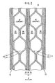
- FIG. 1 is an exploded perspective view showing main components of a fuel cell 10 according to a first embodiment of the present invention.
- FIG. 2 is a cross sectional view showing part of the fuel cell 10.
- the fuel cell 10 is formed by stacking a membrane electrode assembly 12 and separators 13 alternately in a horizontal direction.
- Each of the separators 13 includes first and second horizontally long rectangular metal plates 14, 16 which are stacked together.
- an oxygen-containing gas supply passage 20a for supplying an oxidizing gas such as an oxygen-containing gas, a coolant supply passage 22a for supplying a coolant, and a fuel gas discharge passage 24b for discharging a fuel gas such as a hydrogen-containing gas are arranged vertically in a direction indicated by an arrow C.
- the oxygen-containing gas supply passage 20a, the coolant supply passage 22a, and the fuel gas discharge passage 24b extend through the fuel cell 10 in the stacking direction (horizontal direction) indicated by an arrow A.
- a fuel gas supply passage 24a for supplying the fuel gas, a coolant discharge passage 22b for discharging the coolant, and an oxygen-containing gas discharge passage 20b for discharging the oxygen-containing gas are arranged vertically in the direction indicated by the arrow C.
- the fuel gas supply passage 24a, the coolant discharge passage 22b, and the oxygen-containing gas discharge passage 20b extend through the fuel cell 10 in the direction indicated by the arrow A.
- the membrane electrode assembly 12 comprises an anode 28, a cathode 30, and a solid polymer electrolyte membrane 26 interposed between the anode 28 and the cathode 30.
- the solid polymer electrolyte membrane 26 is formed by impregnating a thin membrane of perfluorosulfonic acid with water, for example.
- Each of the anode 28 and the cathode 30 has a gas diffusion layer such as a carbon paper, and an electrode catalyst layer of platinum alloy supported on carbon particles.
- the carbon particles are deposited uniformly on the surface of the gas diffusion layer.
- the electrode catalyst layer of the anode 28 and the electrode catalyst layer of the cathode 30 are fixed to both surfaces of the solid polymer electrolyte membrane 26, respectively.
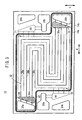
- the first metal plate 14 has an oxygen-containing gas flow field 32 on its surface 14a facing the membrane electrode assembly 12.
- the oxygen-containing gas flow field 32 is connected to the oxygen-containing gas supply passage 20a and the oxygen-containing gas discharge passage 20b.
- the oxygen-containing gas flow field 32 includes an inlet buffer 34 near the oxygen-containing gas supply passage 20a, and an outlet buffer 36 near the oxygen-containing gas discharge passage 20b.
- a plurality of bosses 34a, 36a are formed in the inlet buffer 34 and the outlet buffer 36, respectively.
- the inlet buffer 34 and the outlet buffer 36 are, connected by three oxygen-containing gas flow grooves 38a, 38b, 38c.
- the oxygen-containing gas flow grooves 38a through 38c extend in parallel with each other in a serpentine pattern for allowing the oxygen-containing gas to flow back and forth in the direction indicated by the arrow B, and flows in the direction indicated by the arrow C.
- the oxygen-containing gas flow grooves 38a through 38c have two turn regions T1, T2, and three straight regions extending in the direction indicated by the arrow B, for example.
- a line seal 40 is provided on the surface 14a of the first metal plate 14 around the oxygen-containing gas supply passage 20a, the oxygen-containing gas discharge passage 20b, and the oxygen-containing gas flow field 32 for preventing leakage of the oxygen-containing gas.
- the coolant flow field 42 includes, e.g., two inlet buffers 44, 46 near the coolant supply passage 22a, and includes, e.g., two outlet buffers 48, 50 near the coolant discharge passage 22b.
- the inlet buffers 44, 46 are provided at opposite sides of the coolant supply passage 22a in the direction indicated by the arrow C
- the outlet buffers 48, 50 are provided at opposite sides of the coolant discharge passage 22b in the direction indicated by the arrow C.
- a plurality of bosses 44a, 46a, 48a, and 50a are formed in the inlet buffers 44, 46 and the outlet buffers 48, 50, respectively.
- the coolant supply passage 22a and the inlet buffers 44, 46 are connected by two inlet flow grooves 52, 54, respectively, and the coolant discharge passage 22b and the outlet buffers 48, 50 are connected by two outlet flow grooves 56, 58, respectively.
- the inlet buffer 44 and the outlet buffer 48 are connected by straight flow grooves 60, 62, 64, and 66 extending in the direction indicated by the arrow B.
- the inlet buffer 46 and the outlet buffer 50 are connected by straight flow grooves 68, 70, 72, and 74 extending in the direction indicated by the arrow B.
- Straight flow grooves 76, 78 extending in the direction indicated by the arrow B for a predetermined distance are provided between the straight flow groove 66 and the straight flow groove 68.
- the straight flow grooves 60 through 74 are connected by straight flow grooves 80, 82 which are extending in the direction indicated by the arrow C.
- the straight flow grooves 62 through 72 are connected with each other by straight flow grooves 84, 86 which are extending discontinuously in the direction indicated by the arrow C.
- the straight flow grooves 64, 66, and 76 and the straight flow grooves 68, 70, and 78 are connected with each other by straight flow grooves 88, 90 which are extending discontinuously in the direction indicated by the arrow C, respectively.
- the coolant flow field 42 is partially defined by the first metal plate 14, and partially defined by the second metal plate 16.
- the coolant flow field 42 is formed between the first metal plate 14 and the second metal plate 16 when the first metal plate 14 and the second metal plate 16 are stacked together.
- part of the coolant flow field 42 is formed on the surface 14b where the oxygen-containing gas flow field 32 is not formed on the surface 14a.
- Protrusions on the surface 14b formed by the grooves of the oxygen-containing gas flow field 32 on the surface 14a are not shown for ease of understanding.
- protrusions on the surface 16b formed by the grooves of the fuel gas flow field 96 on the surface 16a are not shown.
- the inlet buffer 44 connected to the coolant supply passage 22a through the two inlet flow grooves 52 is provided on the surface 14b.
- the outlet buffer 50 connected to the coolant discharge passage 22b through the two outlet connection grooves 58 is provided on the surface 14b.
- Grooves 60a, 62a, 64a, and 66a connected to the inlet buffer 44 extend discontinuously in the direction indicated by the arrow B for a predetermined distance.
- the grooves 60a, 62a, 64a, and 66a are formed where the turn region T2 of the oxygen-containing gas flow grooves 38a through 38c and the outlet buffer 36 is not formed.
- Grooves 68a, 70a, 72a, and 74a connected to the outlet buffer 50 extend in the direction indicated by the arrow B.
- the grooves 68a, 70a, 72a, and 74a are formed where the turn region T1 of the oxygen-containing gas flow grooves 38a through 38c and the inlet buffer 34 is not formed.
- the grooves 60a through 78a are part of the straight flow grooves 60 through 78, respectively.
- Grooves 80a through 90a of the straight flow grooves 80 through 90 extend in the direction indicated by the arrow C for a predetermined distance where the serpentine oxygen-containing gas flow grooves 38a through 38c are not formed.
- part of the coolant flow field 42 is formed on the surface 16a of the second metal plate 16 where the fuel gas flow field 96 as described later is not formed.
- the inlet buffer 46 connected to the coolant supply passage 22a, and the outlet buffer 48 connected to the coolant discharge passage 22b are provided.
- Grooves 68b through 74b of the straight flow grooves 68 through 74 connected to the inlet buffer 46 extend discontinuously in the direction indicated by the arrow B for a predetermined distance.
- Grooves 60b through 66b of the straight flow grooves 60 through 66 connected to the outlet buffer 48 extend in a predetermined pattern.
- grooves 80b through 90b of the straight flow grooves 80 through 90 extend in the direction indicated by the arrow C.
- the second metal plate 16 has the fuel gas flow field 96 on its surface 16b facing the membrane electrode assembly 12.
- the fuel gas flow field 96 includes an inlet buffer 98 provided near the fuel gas supply passage 24a, and an outlet buffer 100 provided near the fuel gas discharge passage 24b.
- a plurality of bosses 98a, 100a are formed in the inlet buffer 98 and the outlet buffer 100, respectively.
- the inlet buffer 98 and the outlet buffer 100 are connected by three fuel gas flow grooves 102a, 102b, 102c.
- the fuel gas flow grooves 102a through 102c extend in a serpentine pattern for allowing the fuel gas to flow back and forth in the direction indicated by the arrow B, and flows in the direction indicated by the arrow C.
- the fuel gas flow grooves 102a through 102c are substantially serpentine flow grooves having two turn regions T3, T4, and three straight regions, for example.
- a line seal 40b is provided around the fuel gas flow field 96.
- an oxidizing gas such as an oxygen-containing gas is supplied to the oxygen-containing gas supply passage 20a
- a fuel gas such as a hydrogen-containing gas is supplied to the fuel gas supply passage 24a
- a coolant such as pure water, an ethylene glycol or an oil is supplied to the coolant supply passage 22a.
- the oxygen-containing gas flows from the oxygen-containing gas supply passage 20a into the oxygen-containing gas flow field 32 of the first metal plate 14. As shown in FIG. 3 , the oxygen-containing gas flows through the inlet buffer 34, and is distributed into the oxygen-containing gas flow grooves 38a through 38c. The oxygen-containing gas flows through the oxygen-containing gas flow grooves 38a through 38c in a serpentine pattern along the cathode 30 of the membrane electrode assembly 12.
- the fuel gas flows from the fuel gas supply passage 24a into the fuel gas flow field 96 of the second metal plate 16. As shown in FIG. 9 , the fuel gas flows through the inlet buffer 98, and is distributed into the fuel gas flow grooves 102a through 102c. The fuel gas flows through the fuel gas flow grooves 102a through 102c in a serpentine pattern along the anode 28 of the membrane electrode assembly 12.
- the oxygen-containing gas supplied to the cathode 30, and the fuel gas supplied to the anode 28 are consumed in the electrochemical reactions at catalyst layers of the cathode 30 and the anode 28 for generating electricity.
- the oxygen-containing gas After the oxygen-containing gas is consumed at the cathode 30, the oxygen-containing gas flows into the oxygen-containing gas discharge passage 20b through the outlet buffer 36. Likewise, after the fuel gas is consumed at the anode 28, the fuel gas flows into the fuel gas discharge passage 24b through the outlet buffer 100.
- the coolant supplied to the coolant supply passages 22a flows into the coolant flow field 42 between the first and second metal plates 14, 16. As shown in FIG. 4 , the coolant from the coolant supply passage 22a flows through the inlet flow grooves 52, 54 in the direction indicated by the arrow C, and flows into the inlet buffers 44, 46.
- the coolant is distributed from the inlet buffers 44, 46 into the straight flow grooves 60 through 66, and 68 through 74, and flows horizontally in the direction indicated by the arrow B.
- the coolant also flows through the straight flow grooves 80 through 90, 76, and 78.
- the coolant is supplied to the entire power generation surface of the membrane electrode assembly 12.
- the coolant flows through the outlet buffers 48, 50, and flows into the coolant discharge passages 22b through the outlet flow grooves 56, 58.
- the coolant flow field 42 between the first and second metal plates 14, 16 includes the two inlet buffers 44, 46 connected to the coolant supply passage 22a and the two outlet buffers 48, 50 connected to the coolant discharge passage 22b. Therefore, the coolant flows separately from the coolant supply passage 22a in the direction indicated by the arrow C, and flows into the inlet buffers 44, 46. Then, the coolant flows through the straight flow grooves 60 through 90 along the power generation surface, flows into the outlet buffers 48, 50, and is discharged into the coolant discharge passage 22b.
- the coolant flows along the entire surface of the separator 13 uniformly, and cools the power generation surface of the membrane electrode assembly 12 uniformly.
- the overall power generation performance of the fuel cell 10 is stable.
- part of the coolant flow field 42 is formed where the oxygen-containing gas flow field 32 is not formed on the surface 14a (the oxygen-containing gas flow field 32 is fabricated by pressure forming).
- the inlet buffer 44 is formed at a position below the coolant supply passage 22a where the inlet buffer 34 is not formed
- the outlet buffer 50 is formed at a position above the coolant discharge passage 22b where the outlet buffer 36 is not formed.
- the grooves 60a through 90a each having a predetermined shape are formed where the serpentine oxygen-containing gas flow grooves 38a through 38c are not formed (see FIGS. 3 and 5 ).
- the oxygen-containing gas flow field 32 and the coolant flow field 42 are formed on both surfaces 14a, 14b of the first metal plate 14, respectively.
- part of the coolant flow field 42 is formed on the surface 16a of the second metal plate 16 where the fuel gas flow field 96 on the surface 16b is not formed.
- the inlet buffer 46 is formed at a position above the coolant supply passage 22a where the outlet buffer 100 is not formed.
- the outlet buffer 48 is formed at a position below the coolant discharge passage 22b where the inlet buffer 98 is not formed.
- the grooves 60b through 90b each having a predetermined shape are formed where the serpentine oxygen fuel gas flow grooves 102a through 102c are not formed (see FIGS. 6 and 9 ).
- the fuel gas flow field 96 and the coolant flow field 42 are formed on both surfaces 16a, 16b of the second metal plate 16, respectively.
- the coolant flow field 42 on the first metal plate 14 is constrained by the oxygen-containing gas flow field 32, and the shape of the coolant flow field 42 on the second metal plate 16 is constrained by the fuel gas flow field 96, the coolant flow field 42 on the first metal plate 14 and the coolant flow field 42 on the second metal plate 16 compensate with each other. Therefore, with the simple structure, the coolant flow field 42 having the desired shape is reliably formed in the separator 13.
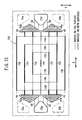
- FIG. 10 is an exploded perspective view showing a fuel cell 110 according to a second embodiment of the present invention.
- the constituent elements that are identical to those of the first embodiment are labeled with the same reference numeral, and description thereof will be omitted.
- the constituent elements that are identical to those of the first embodiment are labeled with the same reference numeral, and description thereof will be omitted.
- the fuel cell 110 is formed by stacking the membrane electrode assembly 12 and separators 112 alternately.
- Each of the separators 112 includes first and second metal plates 114, 116, which are stacked together.
- an oxygen-containing gas supply passage 20a, a coolant supply passage 22a, and an oxygen-containing gas discharge passage 20b are formed.
- a fuel gas supply passage 24a, a coolant discharge passage 22b, and a fuel gas discharge passage 24b are formed.
- the first metal plate 114 has an oxygen-containing gas flow field 118 on its surface 114a facing a cathode 30 of the first metal plate 114.
- the oxygen-containing gas flow field 118 includes an inlet buffer 34 connected to the oxygen-containing gas supply passage 20a through two inlet flow grooves 120 and an outlet buffer 36 connected to the oxygen-containing gas discharge passage 20b through two outlet flow grooves 122.
- the inlet buffer 34 and the outlet buffer 36 are adjacent to each other.
- the inlet buffer 34 and the outlet buffer 36 are connected through oxygen-containing gas flow grooves 124a, 124b, 124c each curved in a substantially U-shape.
- a coolant flow field 126 is formed between the first and second metal plates 114, 116.
- the second metal plate 116 has a fuel gas flow field 125 on its surface 116a facing an anode 28.
- the coolant flow field 126 includes inlet buffers 44, 46 near the coolant supply passage 22a, and outlet buffers 48, 50 near the coolant discharge passage 22b.
- the inlet buffer 44 and the outlet buffer are connected by straight flow grooves 128, 130 extending in the direction indicated by the arrow B.
- the inlet buffer 46 and the outlet buffer 50 are connected by straight flow grooves 132, 134 extending in the direction indicated by the arrow B.
- Straight flow grooves 136, 138 are formed outside the straight flow grooves 128, 134 in the direction indicated by the arrow C. Further, a straight flow groove 140 is formed between the straight flow grooves 130, 132.
- the straight flow grooves 128 through 140 are connected by straight flow grooves 142, 144 extending in the direction indicated by the arrow C.
- the straight flow grooves 128 through 134, and 140 are connected by straight flow grooves 146, 148 extending in the direction indicated by the arrow C.
- the straight flow grooves 130, 132, and 140 are connected by straight flow grooves 150, 152 extending in the direction indicated by the arrow C.
- the first metal plate 114 has outlet buffers 48, 50 connected to the coolant discharge passage 22b on its surface 114b facing the second metal plate 116.
- grooves 128a through 140a of the straight flow grooves 128 through 140 are formed where curved portions of the oxygen-containing containing gas flow grooves 124a through 124c of the oxygen-containing gas flow field 118 are not formed.
- straight flow grooves 146, 148 and 152 are formed in the direction indicated by the arrow C.
- the second metal plate 116 has inlet buffers 44, 46 near the coolant supply passage 22a on its surface 116b facing the first metal plate 114.
- grooves 128b through 140b of the straight flow grooves 128 through 140 are formed where curved portions of the fuel gas flow grooves 131a through 131c are not formed.
- straight flow grooves 142, 146 and 150 are formed in the direction indicated by the arrow C.
- Line seals 40c, 40d are formed on the surfaces 114a, 116a, and unillustrated line seals are formed between the surfaces 114b, 116b.
- the first metal plate 114 has an oxygen-containing gas flow field 118 on the surface 114a.
- the inlet buffer 34 and the outlet buffer 36 are connected through the oxygen-containing gas flow grooves 124a through 124c each curved in a substantially U-shape.
- the second metal plate 116 has the fuel gas flow field 125 on the surface 116a.
- the inlet buffer 98 and the outlet buffer 100 are connected by the fuel gas flow grooves 131a through 131c each curved in a substantially U-shape.
- the coolant flow field 126 is formed between the first metal plate 114 and the second metal plate 116 such that the grooves on the first metal plate 114 and the grooves on the second metal plate 116 compensate with each other.
- the coolant flow field 126 In the coolant flow field 126, the two inlet buffers 44, 46 connected to the coolant supply passage 22a, and the outlet buffers 48, 50 connected to the coolant discharge passage 22b are formed. Therefore, the coolant flows along the surface of the separator 112 uniformly.
- the same advantages as with the first embodiment can be obtained. For example, it is possible to uniformly cool the electrode surface of the membrane electrode assembly 12 to obtain the stable performance of the fuel cell.
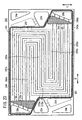
- FIG. 14 is a front view showing a first metal plate 160 of a fuel cell according to a third embodiment of the present invention.
- the first metal plate 160 has an oxygen-containing gas flow field 162 on its surface 160a facing the cathode 30.
- the oxygen-containing gas flow field 162 is connected to the oxygen-containing gas supply passage 20a and the oxygen-containing gas discharge passage 20b.
- the oxygen-containing gas flow field 162 includes three oxygen-containing gas flow grooves 164a through 164c connected between the inlet buffer 34 and the outlet buffer 36.
- the oxygen-containing gas flow grooves 164a through 164c extend in a serpentine pattern for allowing the oxygen-containing gas to flow back and forth in the direction indicated by the arrow B, and flow in the direction indicated by the arrow C.
- Each of the oxygen-containing gas flow grooves 164a through 164c have four turn regions and five straight regions extending in the direction indicated by the arrow B.
- FIG. 15 is a front view showing a second surface 166a of a second metal plate 166 facing the anode 28.
- the second metal plate 166 is stacked on the first metal plate 160.
- a fuel gas flow field 168 is formed on the surface 166a.
- the fuel gas flow field 168 is connected between the fuel gas supply passage 24a and the fuel gas discharge passage 24b.
- the fuel gas flow field 168 includes three fuel gas flow grooves 170a through 170c connected between the inlet buffer 98 and the outlet buffer 100.
- the fuel gas flow grooves 170a through 170c extend in a serpentine pattern for allowing the fuel gas to flow back and forth in the direction indicated by the arrow B, and flow in the direction indicated by the arrow C.
- Each of the fuel gas flow grooves 170a through 170c have four turn regions and five straight regions extending in the direction indicated by the arrow B.
- a coolant flow field 172 is formed between the first and second metal plates 160, 166.
- the coolant flow field 172 includes inlet buffers 44, 46 connected to the coolant supply passage 22a and outlet buffers 48, 50 connected to the coolant discharge passage 22b.
- the inlet buffer 44 and the outlet buffer 48 are connected by four straight flow grooves 174 extending in the direction indicated by the arrow B.
- the inlet buffer 46 and the outlet buffer 50 are connected by four straight flow grooves 176 extending in the direction indicated by the arrow B.
- Eight straight flow grooves 178 are formed in parallel in the direction indicated by the arrow B between the straight flow grooves 174, 176.
- the straight flow grooves 174 through 178 are connected together by two straight flow grooves 180 extending in the direction indicated by the arrow C. Further, the straight flow grooves 174 through 178 are connected by the two straight flow grooves 182 which are shorter than the straight flow groove 174, and two straight flow grooves 184 which are extending discontinuously, and shorter than the straight flow grooves 182.
- the coolant flow field 172 is partially defined by the first metal plate 160, and partially defined by the second metal plate 166. Specifically, as shown in FIG. 14 , on the surface 160b of the first metal plate 160, the inlet buffer 44 and the outlet buffer 50 are formed at positions where the inlet buffer 34 and the outlet buffer 36 are not formed. On the surface 160b, grooves 174a through 178a of the straight flow grooves 174 through 178 extending in the direction indicated by the arrow B are formed, and grooves 180a through 184a of the straight flow grooves 180 through 184 extending in the direction indicated by the arrow C are formed. The grooves 174a through 184a are formed at predetermined positions where the serpentine oxygen-containing gas flow grooves 164a through 164c are not formed.
- the inlet buffer 46 and the outlet buffer 48 are formed on the surface 166b of the second metal plate 166 where the outlet buffer 100 and the inlet buffer 98 are not formed.
- the grooves 174b through 184b as part of the straight flow grooves 174 through 184 are formed at positions where the fuel gas flow grooves 170a through 170c are not affected. Unillustrated line seals are formed between the surfaces 160b, 166b.
- the same advantages as with the first and second embodiments can be obtained.
- the grooves compensate with each other to form the coolant flow field 172 having the desired flow field structure as a whole.
- each of the oxygen-containing gas flow field 162 and the fuel gas flow field 168 have the flow field structure in which four turn regions and five straight regions are formed along the electrode surface. Therefore, the grooves in the flow field are long, the gas flow rate is high, and the gas pressure loss is large. Thus, the water produced in the power generation is discharged efficiently.
- FIG. 17 is a front view of a first metal plate 190 of a fuel cell according to a fourth embodiment of the present invention.
- FIG. 18 is a front view of a second metal plate 192 stacked on the first metal plate 190.
- the first metal plate 190 has an oxygen-containing gas flow field 194 on its surface 190a facing the cathode 30.
- the oxygen-containing gas flow field 194 includes an inlet buffer 196 connected to the oxygen-containing gas supply passage 20a and an outlet buffer 198 connected to the oxygen-containing gas discharge passage 20b.
- a plurality of bosses 196a, 198a are formed in the inlet buffer 196 and the outlet buffer 198, respectively.
- Each of the inlet buffer 196 and the outlet buffer 198 is elongated in the direction indicated by the arrow C.
- the inlet buffer 196 is connected to six oxygen-containing gas flow grooves 200. After the oxygen-containing gas flow grooves 200 extend in the direction in the arrow B, the oxygen-containing gas flow grooves 200 are curved in the direction in the arrow C. Then, every two of the oxygen-containing gas grooves 200 are joined together into the oxygen-containing gas flow grooves 202, and extend in the direction indicated by the arrow B. Every oxygen-containing gas flow grooves 202 is separated into two grooves, i.e., the oxygen-containing gas flow grooves 202 are separated into six oxygen-containing gas flow grooves 204. The oxygen-containing gas flow grooves 204 are curved from the direction indicated by the arrow C to the direction indicated by the arrow B. Then, the oxygen-containing gas flow grooves 204 are connected to the outlet buffer 198.
- the second metal plate 192 has a fuel gas flow field 206 on its surface 192a facing the anode 28.
- the fuel gas flow field 206 includes an inlet buffer 208 connected to the fuel gas supply passage 24a and an outlet buffer 210 connected to the fuel gas discharge passage 24b.
- a plurality of bosses 208a, 210a are formed in the inlet buffer 208, and the outlet buffer 210, respectively.
- Each of the inlet buffer 208 and the outlet buffer 210 is elongated in the direction indicated by the arrow C.
- the inlet buffer 208 is connected to six fuel gas flow grooves 212. After the fuel gas flow grooves 212 extend in the direction indicated by the arrow B, the fuel gas flow grooves 212 are curved in the direction indicated by the arrow C. Every two of the fuel gas flow grooves 212 are joined together to form three fuel gas flow grooves 214. After the fuel gas flow grooves 214 extend in the direction indicated by the arrow B, every fuel gas flow groove 214 is separated into two grooves to form six fuel gas flow grooves 216. After the fuel gas flow grooves 216 extend in the direction indicated by the arrow C, the fuel gas flow grooves 216 are curved in the direction indicated by the arrow B, and connected to the outlet buffer 210.
- a coolant flow field 218 is formed between a surface 190b of the first metal plate 190 and a surface 192b of the second metal plate 192.
- the coolant flow field 218 includes two inlet buffers 220, 222 connected to the coolant supply passage 22a and elongated in the direction indicated by the arrow C, and outlet buffers 224, 226 connected to the coolant discharge passage 22b and elongated in the direction indicated by the arrow C.
- a plurality of bosses 220a, 222a, 224a 226a are formed in the inlet buffers 220, 222, and the outlet buffers 224, 226, respectively.
- the inlet buffer 220 is directly connected to the outlet buffer 224 by six straight flow grooves 228 extending in the direction indicated by the arrow B, and the inlet buffer 222 is directly connected to the outlet buffer 226 by six straight flow grooves 228 extending in the direction indicated by the arrow B.
- Four straight flow grooves 230 are provided on the surface 190a. Each of the straight flow grooves 230 has open ends, and extends in the direction indicated by the arrow B.
- Two straight flow grooves 236 elongated in the direction arrow C are formed near the inlet buffers 220, 222, and the outlet buffers 224, 226.
- Eight straight flow grooves 238 each having a predetermined length are formed between the straight flow grooves 236.
- the coolant flow field 218 is partially defined by the first metal plate 190, and partially defined by the second metal plate 192. As shown in FIG. 17 , on the surface 190b of the first metal plate 190, the inlet buffer 220 and the outlet buffer 226 are formed, and the grooves 228a, 230a, 236a, 238a as part of the straight flow grooves 228, 230, 236, 238 are formed.
- the inlet buffer 222 and the outlet buffer 224 are formed, and the grooves 228b, 230b, 236b, 238b as part of the straight flow grooves 228, 230, 236, 238 are formed.
- Line seals 40g, 40h are formed on the surfaces 190a, 192a, and unillustrated line seals are provided between the surfaces 190b, 192b.
- the number of grooves in the oxygen-containing gas flow field 194 and the number of grooves in the fuel gas flow field 206 change from six to three, and three to six. Therefore, the inlet buffer 196 and the outlet buffer 198 for the oxygen-containing gas and the inlet buffer 208 and the outlet buffer 210 for the fuel gas, and the inlet buffers 220, 222 and the outlet buffers 224, 226 for the coolant are elongated respectively in the direction indicated by the arrow C. Thus, it is possible to supply the oxygen-containing gas, the fuel gas, and the coolant more uniformly and smoothly along the electrode surfaces.
- FIG. 20 is a front view showing a first metal plate 240 of a fuel cell according to a fifth embodiment.
- FIG. 21 is a front view showing a second metal plate 242 stacked on the first metal plate 240.
- the first metal plate 240 has an oxygen-containing gas flow field 244 on its surface 240a facing the cathode.
- the oxygen-containing gas flow field 244 includes four oxygen-containing gas flow grooves 246.
- Each of the oxygen-containing gas flow grooves 246 has a serpentine pattern having two turn regions and three straight regions for allowing the oxygen-containing gas to flow back and forth in the direction indicated by the arrow B.
- the oxygen-containing gas flow grooves 246 are connected between the inlet buffer 34 and the outlet buffer 36.
- the second metal plate 242 has a fuel gas flow field 248 on its surface 242a facing the anode 28.
- the fuel gas flow field 248 includes three fuel gas flow grooves 250.
- the fuel gas flow grooves 250 has a serpentine pattern having four turn regions and five straight regions for allowing the fuel gas to flow back and forth in the direction indicated by the arrow B.
- the fuel gas flow grooves 250 are connected between an inlet buffer 98 and an outlet buffer 100.
- a coolant flow field 252 is connected between the first and second metal plates 240, 242. As shown in FIG. 22 , the coolant flow field 252 includes inlet buffers 254, 256 connected to the coolant supply passage 22a, and outlet buffers 258, 260 connected to the coolant discharge passage 22b. A plurality of bosses 254a, 256a are formed in the inlet buffers 254, 256, respectively, and a plurality of bosses 258a, 260a are formed in the outlet buffers 258, 260, respectively.
- the inlet buffer 254 and the outlet buffer 258 are connected directly by four straight grooves 262 extending in the direction indicated by the arrow B, and the inlet buffer 256 and the outlet buffer 260 are connected by four straight grooves 262 extending in the direction indicated by the arrow B.
- Ends of two straight flow grooves 264 are connected to the inlet buffer 256, and the other ends of the straight flow grooves 264 terminate at an area adjacent to the outlet buffer 260.
- Ends of two straight flow grooves 266 are connected to the outlet buffer 258, and the other ends of the straight flow grooves 266 terminate at an area adjacent to the inlet buffer 254.
- four straight flow grooves 268 extending in the direction indicated by the arrow B are provided. Both ends of the straight flow grooves 268 are open.
- Straight flow grooves 270 elongated in the direction indicated by the arrow C are provided near the inlet buffers 254, 256, and near the outlet buffers 258, 260. Further, eight straight flow grooves 272 each having a predetermined length in the direction indicated by the arrow C are formed between the straight flow grooves 270.
- the surface 240b of the first metal plate 240 and the surface 242b of the second metal plate 242 face each other.
- the coolant flow field 252 is partially defined on the surface 240b of the first metal plate 240, and partially defined on the surface 242b of the second metal plate 242.
- the inlet buffer 254 and the outlet buffer 260 are formed on the surface 240b of the first metal plate 240.
- grooves 262a through 272a as part of the straight flow grooves 262 through 272 are formed on the surface 240b of the first metal plate 240.
- the inlet buffer 256 and the outlet buffer 258 are formed on the surface 242b of the second metal plate 242. Further, grooves 262b through 272b as part of the straight flow grooves 262 through 272 are formed on the surface 242a of the second metal plate 242. Line seals 40i, 40j are formed on the surfaces 240a, 242a. Unillustrated line seals are provided between the surfaces 240b, 242b.
- the fifth embodiment is advantageous in that even if the oxygen-containing gas flow field 244 and the fuel gas flow field 248 formed on the first and second metal plates 240, 242 have different shapes, it is possible to form the coolant flow field 252 having a predetermined shape between the first and second metal plates 240, 242.
- FIG. 23 is an exploded perspective view showing main components of a fuel cell 300 according to a sixth embodiment of the present invention.
- the fuel cell 300 is formed by stacking the membrane electrode assembly 12 and separators 302 alternately.
- the separator 302 includes first and second metal plates 304, 306 which are stacked together.
- the coolant supply passage 22a is connected to the first inlet buffer 44 through a first inlet connection passage 308, and connected to the second inlet buffer 46 through a second inlet connection passage 310.
- the coolant discharge passage 22b is connected to the first outlet buffer 48 through a first outlet connection passage 312, and connected to the second outlet buffer 50 through a second outlet connection passage 314.
- the first inlet connection passage 308 comprises, for example, two flow grooves
- the second inlet connection passage 310 comprises, for example, six flow grooves.
- the first outlet connection passage 312 comprises six flow grooves
- the second outlet connection passage 314 comprises two flow grooves.
- the number of flow grooves in the first inlet connection passage 308 is not limited to “two", and the number of flow grooves in the second inlet connection passage 310 is not limited to “six”.
- the number of flow grooves in the first outlet connection passage 312 is not limited to “six”
- the number of flow grooves in the second outlet connection passage 314 is not limited to "two”.
- the first and second inlet connection passages 308, 310 connecting the coolant supply passage 22a and the inlet buffers 44, 46 are provided.
- the first inlet connection passage 308 comprises two flow grooves
- the second inlet connection passage 310 includes six flow grooves.
- the first and second outlet connection passages 312, 314 connecting the coolant discharge passage 22b and the outlet buffers 48, 50 are provided.
- the first outlet connection passage 312 comprises six flow grooves
- the second outlet connection passage 314 comprises two flow grooves.
- a position near the inlet buffer 44 is defined as the position P1
- a position near the inlet buffer 46 is defined as the position P2
- the flow resistance from the coolant supply passage 22a to the position P1 is larger than the flow resistance from the coolant supply passage 22a to the position P2. Therefore, the pressure of the coolant applied to the position P2 is larger than the pressure of the coolant applied to the position P1.
- the coolant flows from the position P2 to the position P1. It is possible to prevent stagnation of the coolant, and produce the flow of the coolant from the position P2 to the position P1 in the coolant flow field 42.
- the flow rate and temperature distribution in the coolant flow field 42 were confirmed in a comparative example and the sixth embodiment.
- the number of flow grooves of the first inlet connection passage 308 and the number of flow grooves of the second inlet connection passage 310 are the same, and the number of the flow grooves of the first outlet connection passage 312 and the number of flow grooves of the second outlet connection passage 314 are the same.
- the confirmation was made around positions Pa, Pb, Pc, and Pd along a central line T connecting the coolant supply passage 22a and the coolant discharge passage 22b.
- the positions Pa, Pd are end positions of the coolant flow field 42.
- the distance (H) between the position Pb and the position Pa and the distance (H) between the position Pc and the position Pd were set to 1/2 of the entire flow field width (2H) of the coolant flow field 42.
- the temperature was high near the positions Pa, Pb and the positions Pc, Pd since the coolant did not flow smoothly.
- the coolant flowed smoothly by the pressure difference. Therefore, in the temperature distribution of the sixth embodiment, the temperature increased from the coolant supply passage 22a to the coolant discharge passage 22b.
- the coolant flows between the first and second metal plates of the separator.
- the coolant is supplied from the coolant supply passage separately into two or more inlet buffers. After the coolant flows through the straight flow grooves into two or more outlet buffers, the coolant is discharged into the coolant discharge passage. Therefore, the coolant flows along the surface of the separator uniformly, and cools the separator surface uniformly. Thus, the stable power generation performance can be achieved.
- the numbers of the flow grooves of the respective inlet connection passages are different, and the number of the flow grooves of the respective outlet connection passages are different.
- the desired flow rate and the desired flow condition of the coolant in the coolant flow field are achieved. Accordingly, the coolant flows in the separator surface uniformly, and cools the entire electrode surface uniformly. Thus, the stable power generation performance can be achieved.
Landscapes
- Life Sciences & Earth Sciences (AREA)
- Engineering & Computer Science (AREA)
- Manufacturing & Machinery (AREA)
- Sustainable Development (AREA)
- Sustainable Energy (AREA)
- Chemical & Material Sciences (AREA)
- Chemical Kinetics & Catalysis (AREA)
- Electrochemistry (AREA)
- General Chemical & Material Sciences (AREA)
- Fuel Cell (AREA)
Claims (15)
- Brennstoffzelle, die durch abwechselndes Stapeln einer Elektrolyt-Elektrode-Anordnung (12) und Trenneinrichtungen (13) gebildet ist, wobei die Elektrolyt-Elektrode-Anordnung (12) eine Anode (28) und eine Katode (30) enthält und ein Elektrolyt (26) zwischen der Anode (28) und der Katode (30) eingeschoben ist,
wobei ein Brennstoffgas-Zufuhrdurchlass (24a), ein Zufuhrdurchlass (20a) für sauerstoffhaltiges Gas, ein Brennstoffgas-Entladedurchlass (24b), ein Entladedurchlass (20b) für sauerstoffhaltiges Gas und ein Kühlmittel-Entladedurchlass (22b) durch die Brennstoffzelle in einer Stapelrichtung der Brennstoffzelle verlaufen;
wobei die Trenneinrichtung (13) wenigstens erste und zweite Metallplatten (14, 16) enthält, die gemeinsam gestapelt sind; und
wobei die erste Metallplatte (14) ein Strömungsfeld (32) für sauerstoffhaltiges Gas aufweist, das einen gekrümmten Strömungsdurchlass zum Zuführen eines sauerstoffhaltigen Gases längs der Katode (30) enthält, und die zweite Metallplatte (16) ein Brennstoffgas-Strömungsfeld (96) aufweist, das einen gekrümmten Strömungsdurchlass zum Zuführen eines Brennstoffgases längs der Anode (28) enthält;
dadurch gekennzeichnet, dass ein Kühlmittel-Strömungsfeld (42) zwei oder mehr Einlasspuffer (44, 46), wovon jeder mit dem Kühlmittel-Zufuhrdurchlass (22a) verbunden ist, wobei die zwei oder mehr Einlasspuffer (44, 46) voneinander getrennt sind; zwei oder mehr Auslasspuffer (48, 50), wovon jeder mit dem Kühlmittel-Entladedurchlass (22b) verbunden ist, wobei die zwei oder mehr Auslasspuffer (48, 50) voneinander getrennt sind, und geradlinige Strömungsrillen (60), die zwischen die zwei oder mehr getrennten Einlasspuffer (44, 46) und die zwei oder mehr getrennten Auslasspuffer (48, 50) geschaltet sind, enthält, zwischen der ersten und der zweiten Metallplatte (14, 16) vorgesehen ist. - Brennstoffzelle nach Anspruch 1, wobei ein erster Einlasspuffer (44), der mit dem Kühlmittel-Zufuhrdurchlass (22a) verbunden ist, und ein erster Auslasspuffer (50), der mit dem Kühlmittel-Entladedurchlass (22b) verbunden ist, an der ersten Metallplatte (14) ausgebildet sind; und
ein zweiter Einlasspuffer (46), der mit dem Kühlmittel-Zufuhrdurchlass (22a) verbunden ist, und ein zweiter Auslasspuffer (50), der mit dem Kühlmittel-Entladedurchlass (22b) verbunden ist, an Positionen, die von Positionen des ersten Einlasspuffers (44) und des ersten Auslasspuffers (50) verschieden sind, an der zweiten Metallplatte (16) ausgebildet sind. - Brennstoffzelle nach Anspruch 1 oder 2, wobei das Brennstoffgas-Strömungsfeld (96) einen Einlasspuffer (98), der mit dem Brennstoffgas-Zufuhrdurchlass (24a) verbunden ist, einen Auslasspuffer (100), der mit dem Brennstoffgas-Entladedurchlass (24b) verbunden ist, und eine gekrümmte Strömungsrille (102a), die sich längs der zweiten Metallplatte (16) erstreckt und zwischen den Einlasspuffer (98) und den Auslasspuffer (100) geschaltet ist, enthält; und
das Brennstoffgas-Strömungsfeld (96) einen Einlasspuffer (34), der mit dem Zufuhrdurchlass (20a) für sauerstoffhaltiges Gas verbunden ist, einen Auslasspuffer (36), der mit dem Entladedurchlass (20b) für sauerstoffhaltiges Gas verbunden ist, und eine gekrümmte Strömungsrille (38a), die sich längs der ersten Metallplatte (14) erstreckt und zwischen den Einlasspuffer (34) und den Auslasspuffer (36) geschaltet ist, enthält. - Brennstoffzelle nach Anspruch 1, 2 oder 3, wobei das Brennstoffgas-Strömungsfeld (96) und das Strömungsfeld (32) für sauerstoffhaltiges Gas jeweils einen serpentinenförmigen Strömungsdurchlass enthalten.
- Brennstoffzelle nach Anspruch 4, wobei die Anzahl von Rillen in dem serpentinenförmigen Strömungsdurchlass abnimmt und dann zunimmt.
- Brennstoffzelle nach einem vorhergehenden Anspruch, wobei das Brennstoffgas-Strömungsfeld (125) und das Strömungsfeld (118) für sauerstoffhaltiges Gas jeweils einen U-förmigen Strömungsdurchlass enthalten.
- Brennstoffzelle nach einem vorhergehenden Anspruch, wobei die erste und die zweite Metallplatte (14, 16) jeweils eine horizontal lange rechtwinklige Form aufweisen und in einer horizontalen Richtung gestapelt sind.
- Brennstoffzelle nach Anspruch 7, wobei von den sechs Durchlässen, die den Brennstoffgas-Zufuhrdurchlass (24a), den Zufuhrdurchlass (20a) für sauerstoffhaltiges Gas, den Kühlmittel-Zufuhrdurchlass (22a), den Brennstoffgas-Entladedurchlass (24b), den Entladedurchlass (20b) für sauerstoffhaltiges Gas und den Kühlmittel-Entladedurchlass (22b) umfassen, drei Durchlässe durch ein linkes Ende der ersten und zweiten Metallplatten (14, 16) verlaufen und die anderen drei Durchlässe durch ein rechtes Ende der ersten und zweiten Metallplatten (14, 16) verlaufen.
- Brennstoffzelle nach Anspruch 1, wobei
zwei oder mehr separate Einlasspuffer (44, 46) jeweils mit dem Kühlmittel-Zufuhrdurchlass (22a) über Einlassverbindungsdurchlässe verbunden sind, zwei oder mehr Auslasspuffer (48, 50) jeweils mit dem Kühlmittel-Entladedurchlass (22b) über Auslassverbindungsdurchlässe verbunden sind;
wenigstens die Anzahl von Rillen in einem ersten Einlassverbindungsdurchlass (308), der den ersten Einlasspuffer (44) mit dem Kühlmittel-Zufuhrdurchlass (22a) verbindet, und die Anzahl von Rillen in einem zweiten Einlassverbindungsdurchlass (310), der den zweiten Einlasspuffer (46) mit dem Kühlmittel-Zufuhrdurchlass (22a) verbindet, verschieden sind; und
wenigstens die Anzahl von Rillen in einem ersten Auslassverbindungsdurchlass (312), der den ersten Auslasspuffer (48) mit dem Kühlmittel-Entladedurchlass (22b) verbindet, und die Anzahl von Rillen in einem zweiten Auslassverbindungsdurchlass (314), der den zweiten Auslasspuffer (50) mit dem Kühlmittel-Entladedurchlass (22b) verbindet, verschieden sind. - Brennstoffzelle nach Anspruch 9, wobei ein Strömungsfeld (32) für sauerstoffhaltiges Gas, das einen gekrümmten Strömungsdurchlass enthält, an einer Oberfläche der ersten Metallplatte (304) zum Zuführen eines sauerstoffhaltigen Gases längs der Katode (30) ausgebildet ist und ein Brennstoffgas-Strömungsfeld (96), das einen gekrümmten Strömungsdurchlass enthält, an einer Oberfläche der zweiten Metallplatte (306) zum Zuführen eines Brennstoffgases längs der Anode (28) ausgebildet ist; und
ein erster Einlasspuffer (44), der mit dem Kühlmittel-Zufuhrdurchlass (22a) verbunden ist, und ein erster Auslasspuffer (50), der mit dem Kühlmittel-Entladedurchlass (22b) verbunden ist, an der anderen Oberfläche der ersten Metallplatte (304) ausgebildet sind; und
ein zweiter Einlasspuffer (46), der mit dem Kühlmittel-Zufuhrdurchlass (22a) verbunden ist, und ein zweiter Auslasspuffer (48), der mit dem Kühlmittel-Entladedurchlass (22b) verbunden ist, an Positionen, die von Positionen des ersten Einlasspuffers (44) und des ersten Auslasspuffers (50) verschieden sind, an der anderen Oberfläche der zweiten Metallplatte (306) ausgebildet sind. - Brennstoffzelle nach Anspruch 9 oder 10, wobei das Brennstoffgas-Strömungsfeld (96) und das Strömungsfeld (32) für sauerstoffhaltiges Gas jeweils einen serpentinenförmigen Strömungsdurchlass enthalten.
- Brennstoffzelle nach Anspruch 9, 10 oder 11, wobei jede von den ersten und zweiten Metallplatten (304, 306) eine horizontal lange rechtwinklige Form aufweist und in einer horizontalen Richtung gestapelt ist.
- Brennstoffzelle nach Anspruch 12, wobei der Reaktionsmittelgas-Zufuhrdurchlass einen Brennstoffgas-Zufuhrdurchlass (24a) und einen Zufuhrdurchlass (20a) für sauerstoffhaltiges Gas umfasst und der Reaktionsmittelgas-Entladedurchlass einen Brennstoffgas-Entladedurchlass (24b) und einen Entladedurchlass (20b) für sauerstoffhaltiges Gas umfasst; und
von den sechs Durchlässen, die den Brennstoffgas-Zufuhrdurchlass (24a), den Zufuhrdurchlass (20a) für sauerstoffhaltiges Gas, den Kühlmittel-Zufuhrdurchlass (22a), den Brennstoffgas-Entladedurchlass (24b), den Entladedurchlass (20b) für sauerstoffhaltiges Gas und den Kühlmittel-Entladedurchlass (22b) umfassen, drei Durchlässe durch ein linkes Ende der ersten und zweiten Metallplatten (304, 306) verlaufen und die anderen drei Durchlässe durch ein rechtes Ende der ersten und zweiten Metallplatten (304, 306) verlaufen. - Brennstoffzelle nach Anspruch 4, wobei der serpentinenförmige Strömungsdurchlass des Strömungsfelds (32) eines sauerstoffhaltigen Gases und der serpentinenförmige Strömungsdurchlass des Brennstoffgas-Strömungsfelds (96) die gleiche Anzahl von Kurvenbereichen aufweisen.
- Brennstoffzelle nach Anspruch 14, wobei von den sechs Durchlässen, die die den Brennstoffgas-Zufuhrdurchlass (24a), den Zufuhrdurchlass (20a) für sauerstoffhaltiges Gas, den Kühlmittel-Zufuhrdurchlass (22a), den Brennstoffgas-Entladedurchlass (24b), den Entladedurchlass (20b) für sauerstoffhaltiges Gas und den Kühlmittel-Entladedurchlass (22b) umfassen, drei Durchlässe durch ein linkes Ende der ersten und zweiten Metallplatten (14, 16) verlaufen und die anderen drei Durchlässe durch ein rechtes Ende der ersten und zweiten Metallplatten (14, 16) verlaufen.
Applications Claiming Priority (5)
| Application Number | Priority Date | Filing Date | Title |
|---|---|---|---|
| JP2002313242 | 2002-10-28 | ||
| JP2002313242A JP4344513B2 (ja) | 2002-10-28 | 2002-10-28 | 燃料電池 |
| JP2002333742 | 2002-11-18 | ||
| JP2002333742A JP4268400B2 (ja) | 2002-11-18 | 2002-11-18 | 燃料電池 |
| PCT/JP2003/013755 WO2004038840A1 (ja) | 2002-10-28 | 2003-10-28 | 燃料電池 |
Publications (3)
| Publication Number | Publication Date |
|---|---|
| EP1557893A1 EP1557893A1 (de) | 2005-07-27 |
| EP1557893A4 EP1557893A4 (de) | 2008-03-12 |
| EP1557893B1 true EP1557893B1 (de) | 2012-03-07 |
Family
ID=32179121
Family Applications (1)
| Application Number | Title | Priority Date | Filing Date |
|---|---|---|---|
| EP03758972A Expired - Lifetime EP1557893B1 (de) | 2002-10-28 | 2003-10-28 | Brennstoffzelle |
Country Status (4)
| Country | Link |
|---|---|
| US (1) | US7745062B2 (de) |
| EP (1) | EP1557893B1 (de) |
| CA (1) | CA2497258C (de) |
| WO (1) | WO2004038840A1 (de) |
Families Citing this family (9)
| Publication number | Priority date | Publication date | Assignee | Title |
|---|---|---|---|---|
| CN100541891C (zh) | 2005-01-13 | 2009-09-16 | 丰田自动车株式会社 | 燃料电池及燃料电池用隔板 |
| JP5082467B2 (ja) * | 2007-01-29 | 2012-11-28 | トヨタ自動車株式会社 | 燃料電池、および、燃料電池を構成するセパレータ |
| KR101240976B1 (ko) * | 2010-11-12 | 2013-03-11 | 현대자동차주식회사 | 차량용 연료전지의 냉각 시스템 |
| EP2775557B1 (de) * | 2011-11-02 | 2019-09-11 | NGK Sparkplug Co., Ltd. | Brennstoffzelle |
| US9350029B2 (en) * | 2012-11-21 | 2016-05-24 | Honda Motor Co., Ltd. | Fuel cell stack |
| JP5749703B2 (ja) * | 2012-12-10 | 2015-07-15 | 本田技研工業株式会社 | 燃料電池スタック |
| KR101959460B1 (ko) * | 2015-05-27 | 2019-03-18 | 주식회사 엘지화학 | 분리판 및 이를 포함하는 연료 전지 스택 |
| CN114628721B (zh) * | 2020-12-14 | 2024-05-07 | 中国科学院大连化学物理研究所 | 一种燃料电池电堆 |
| CN115241514B (zh) * | 2022-08-04 | 2024-08-16 | 中南大学 | 一种固体氧化物燃料电池/电解池电堆及制氢方法 |
Family Cites Families (18)
| Publication number | Priority date | Publication date | Assignee | Title |
|---|---|---|---|---|
| US5230966A (en) * | 1991-09-26 | 1993-07-27 | Ballard Power Systems Inc. | Coolant flow field plate for electrochemical fuel cells |
| JPH08222237A (ja) | 1995-02-14 | 1996-08-30 | Aisin Aw Co Ltd | 燃料電池用セパレータ |
| JP3713912B2 (ja) * | 1996-08-08 | 2005-11-09 | アイシン精機株式会社 | 燃料電池のガス通路板 |
| CA2256276C (en) * | 1997-12-18 | 2003-04-08 | Toyota Jidosha Kabushiki Kaisha | Fuel cell and separator for the same |
| US6410178B1 (en) * | 1998-05-08 | 2002-06-25 | Aisin Takaoka Co., Ltd. | Separator of fuel cell and method for producing same |
| US6261710B1 (en) * | 1998-11-25 | 2001-07-17 | Institute Of Gas Technology | Sheet metal bipolar plate design for polymer electrolyte membrane fuel cells |
| JP4120072B2 (ja) | 1998-11-27 | 2008-07-16 | アイシン精機株式会社 | 固体高分子電解質型燃料電池用セパレータ及び固体高分子電解質型燃料電池 |
| JP2000323149A (ja) * | 1999-05-07 | 2000-11-24 | Mitsubishi Heavy Ind Ltd | 燃料電池用セパレータ及び製造装置 |
| JP4590047B2 (ja) * | 1999-08-13 | 2010-12-01 | 本田技研工業株式会社 | 燃料電池スタック |
| JP3780775B2 (ja) | 1999-10-15 | 2006-05-31 | 富士電機ホールディングス株式会社 | 固体高分子電解質型燃料電池 |
| JP2001250569A (ja) | 2000-03-06 | 2001-09-14 | Toyota Motor Corp | 燃料電池及びその集電板 |
| AU5532601A (en) | 2000-04-12 | 2001-10-30 | Univ Rochester | Targeted vaccine delivery systems |
| JP3648128B2 (ja) * | 2000-05-02 | 2005-05-18 | 本田技研工業株式会社 | 燃料電池 |
| JP2002075395A (ja) | 2000-08-24 | 2002-03-15 | Toyota Motor Corp | 燃料電池用セパレータおよびそれを用いた固体高分子型燃料電池 |
| US20020055031A1 (en) | 2000-11-09 | 2002-05-09 | Honda Giken Kogyo Kabushiki Kaisha | Fuel cell |
| CN1293661C (zh) | 2000-12-05 | 2007-01-03 | 松下电器产业株式会社 | 高分子电解质型燃料电池及其运行方法 |
| JP4516229B2 (ja) | 2001-03-06 | 2010-08-04 | 本田技研工業株式会社 | 固体高分子型セルアセンブリ |
| JP4344500B2 (ja) * | 2002-01-07 | 2009-10-14 | 本田技研工業株式会社 | 燃料電池 |
-
2003
- 2003-10-28 WO PCT/JP2003/013755 patent/WO2004038840A1/ja not_active Ceased
- 2003-10-28 US US10/533,182 patent/US7745062B2/en not_active Expired - Fee Related
- 2003-10-28 CA CA002497258A patent/CA2497258C/en not_active Expired - Fee Related
- 2003-10-28 EP EP03758972A patent/EP1557893B1/de not_active Expired - Lifetime
Also Published As
| Publication number | Publication date |
|---|---|
| EP1557893A4 (de) | 2008-03-12 |
| US20060003206A1 (en) | 2006-01-05 |
| WO2004038840A1 (ja) | 2004-05-06 |
| US7745062B2 (en) | 2010-06-29 |
| CA2497258A1 (en) | 2004-05-06 |
| CA2497258C (en) | 2009-05-12 |
| EP1557893A1 (de) | 2005-07-27 |
Similar Documents
| Publication | Publication Date | Title |
|---|---|---|
| US7867666B2 (en) | Fuel cell with triangular buffers for reactant gas and coolant | |
| EP1239530B1 (de) | Brennstoffzellenanordnung mit festen Polymerelektrolyten, Brennstoffzellenstapel und Verfahren zur Reaktionsgasversorgung in der Brennstoffzellenanordnung | |
| CA2415601C (en) | Fuel cell separator with projecting protrusions and guide ribs | |
| JP2000231929A (ja) | 燃料電池 | |
| US20040106028A1 (en) | Fuel cell | |
| CN102460798A (zh) | 燃料电池 | |
| US7569301B2 (en) | Fuel cell | |
| EP1557893B1 (de) | Brennstoffzelle | |
| EP2023432B1 (de) | Brennstoffzelle | |
| US7951508B2 (en) | Fuel cell | |
| CA2594530C (en) | Fuel cell separator | |
| US8053125B2 (en) | Fuel cell having buffer and seal for coolant | |
| JP4031952B2 (ja) | 燃料電池 | |
| JP2004171824A (ja) | 燃料電池 | |
| JP4344513B2 (ja) | 燃料電池 | |
| EP1547181B1 (de) | Brennstoffzelle | |
| GB2404492A (en) | Fuel cell | |
| KR100654303B1 (ko) | 연료전지용 분리판 및 그 분리판이 구비된 연료전지 | |
| KR20070035859A (ko) | 바이폴라 플레이트 및 이를 채용한 연료전지 스택 |
Legal Events
| Date | Code | Title | Description |
|---|---|---|---|
| PUAI | Public reference made under article 153(3) epc to a published international application that has entered the european phase |
Free format text: ORIGINAL CODE: 0009012 |
|
| 17P | Request for examination filed |
Effective date: 20050207 |
|
| AK | Designated contracting states |
Kind code of ref document: A1 Designated state(s): AT BE BG CH CY CZ DE DK EE ES FI FR GB GR HU IE IT LI LU MC NL PT RO SE SI SK TR |
|
| RBV | Designated contracting states (corrected) |
Designated state(s): DE FR GB |
|
| A4 | Supplementary search report drawn up and despatched |
Effective date: 20080213 |
|
| 17Q | First examination report despatched |
Effective date: 20090319 |
|
| GRAP | Despatch of communication of intention to grant a patent |
Free format text: ORIGINAL CODE: EPIDOSNIGR1 |
|
| RIN1 | Information on inventor provided before grant (corrected) |
Inventor name: SUGIURA, SEIJI,C/O KABUSHIKI KAISHA HONDA GIJYUTSU Inventor name: MOURI, MASAHIRO,C/O KABUSHIKI KAISHA HONDA GIJYUTS Inventor name: GOTO, SHUHEI,C/O KABUSHIKI KAISHA HONDA GIJYUTSU K |
|
| GRAS | Grant fee paid |
Free format text: ORIGINAL CODE: EPIDOSNIGR3 |
|
| GRAA | (expected) grant |
Free format text: ORIGINAL CODE: 0009210 |
|
| AK | Designated contracting states |
Kind code of ref document: B1 Designated state(s): DE FR GB |
|
| REG | Reference to a national code |
Ref country code: GB Ref legal event code: FG4D |
|
| REG | Reference to a national code |
Ref country code: DE Ref legal event code: R096 Ref document number: 60340211 Country of ref document: DE Effective date: 20120510 |
|
| PLBE | No opposition filed within time limit |
Free format text: ORIGINAL CODE: 0009261 |
|
| STAA | Information on the status of an ep patent application or granted ep patent |
Free format text: STATUS: NO OPPOSITION FILED WITHIN TIME LIMIT |
|
| REG | Reference to a national code |
Ref country code: DE Ref legal event code: R084 Ref document number: 60340211 Country of ref document: DE Effective date: 20121116 |
|
| 26N | No opposition filed |
Effective date: 20121210 |
|
| REG | Reference to a national code |
Ref country code: DE Ref legal event code: R097 Ref document number: 60340211 Country of ref document: DE Effective date: 20121210 |
|
| GBPC | Gb: european patent ceased through non-payment of renewal fee |
Effective date: 20121028 |
|
| REG | Reference to a national code |
Ref country code: FR Ref legal event code: ST Effective date: 20130628 |
|
| PG25 | Lapsed in a contracting state [announced via postgrant information from national office to epo] |
Ref country code: GB Free format text: LAPSE BECAUSE OF NON-PAYMENT OF DUE FEES Effective date: 20121028 |
|
| PG25 | Lapsed in a contracting state [announced via postgrant information from national office to epo] |
Ref country code: FR Free format text: LAPSE BECAUSE OF NON-PAYMENT OF DUE FEES Effective date: 20121031 |
|
| PGFP | Annual fee paid to national office [announced via postgrant information from national office to epo] |
Ref country code: DE Payment date: 20171025 Year of fee payment: 15 |
|
| REG | Reference to a national code |
Ref country code: DE Ref legal event code: R119 Ref document number: 60340211 Country of ref document: DE |
|
| PG25 | Lapsed in a contracting state [announced via postgrant information from national office to epo] |
Ref country code: DE Free format text: LAPSE BECAUSE OF NON-PAYMENT OF DUE FEES Effective date: 20190501 |