EP1557805B1 - Strahlungsdetektor mit Linsen und Spiegeln - Google Patents
Strahlungsdetektor mit Linsen und Spiegeln Download PDFInfo
- Publication number
- EP1557805B1 EP1557805B1 EP20040293161 EP04293161A EP1557805B1 EP 1557805 B1 EP1557805 B1 EP 1557805B1 EP 20040293161 EP20040293161 EP 20040293161 EP 04293161 A EP04293161 A EP 04293161A EP 1557805 B1 EP1557805 B1 EP 1557805B1
- Authority
- EP
- European Patent Office
- Prior art keywords
- mirrors
- vision
- detection
- detection device
- fact
- Prior art date
- Legal status (The legal status is an assumption and is not a legal conclusion. Google has not performed a legal analysis and makes no representation as to the accuracy of the status listed.)
- Expired - Lifetime
Links
Images


Classifications
-
- G—PHYSICS
- G08—SIGNALLING
- G08B—SIGNALLING SYSTEMS, e.g. PERSONAL CALLING SYSTEMS; ORDER TELEGRAPHS; ALARM SYSTEMS
- G08B13/00—Burglar, theft or intruder alarms
- G08B13/18—Actuation by interference with heat, light, or radiation of shorter wavelength; Actuation by intruding sources of heat, light, or radiation of shorter wavelength
- G08B13/189—Actuation by interference with heat, light, or radiation of shorter wavelength; Actuation by intruding sources of heat, light, or radiation of shorter wavelength using passive radiation detection systems
- G08B13/19—Actuation by interference with heat, light, or radiation of shorter wavelength; Actuation by intruding sources of heat, light, or radiation of shorter wavelength using passive radiation detection systems using infrared-radiation detection systems
- G08B13/193—Actuation by interference with heat, light, or radiation of shorter wavelength; Actuation by intruding sources of heat, light, or radiation of shorter wavelength using passive radiation detection systems using infrared-radiation detection systems using focusing means
Definitions
- the present invention relates to a radiation detection device, in particular infrared radiation, generally used as a component of an alarm system for detecting the presence of intruders.
- a radiation detection device placed in height against a wall, which comprises a radiation sensor having a sensitive face oriented towards the front and a lens system placed in front and at a distance from this sensor, focusing towards the latter the radiation from detection or vision fields extending in front of the lens system, inclined downwards and distributed.
- a radiation detection device placed in height against a wall, which comprises a radiation sensor having a sensitive face oriented towards the front and a lens system placed in front and at a distance from this sensor, focusing towards the latter the radiation from detection or vision fields extending in front of the lens system, inclined downwards and distributed.
- a detection device which comprises a radiation sensor having a rearward sensitive face and a mirror system placed behind the radiation sensor and comprising horizontal rows of substantially identical focal mirrors in rows and different from one row to another to deflect radiation coming from forwardly inclined and distributed forward detection or vision fields to the radiation sensor.
- a detection device which comprises a radiation sensor having a rearward sensitive face and a mirror system placed behind the radiation sensor and comprising horizontal rows of substantially identical focal mirrors in rows and different from one row to another to deflect radiation coming from forwardly inclined and distributed forward detection or vision fields to the radiation sensor.
- the present invention aims to provide an improvement to the radiation detection devices, in particular infrared radiation.
- the device for detecting radiation comprises a radiation sensor comprising, on a frontal plane, at least one element sensitive to radiation and having an optical center and a main axis of vision, and a lens system placed in front of and away from the sensor, focussing thereto radiation from detection or vision fields extending in front of the lens system and determining, between the lens system and the sensor, fields focal points located in an enveloping volume,
- the detection device further comprises an additional system of mirrors situated laterally to said enveloping volume and comprising at least two mirrors focusing towards said sensor the radiation coming from additional detection or vision fields not passing through said lens system. and having different focal lengths such that said additional detection or vision fields have different angular apertures.
- said at least two mirrors preferably determine, between the mirror system and the sensor, additional focusing fields whose projections on said front plane are angularly offset.
- said at least two mirrors may advantageously determine, between the mirror system and the sensor, additional focusing fields whose projections on a plane containing said main axis substantially coincide.
- said mirror system preferably comprises at least one central mirror having a plane of symmetry containing said main axis and determining a detection or detection field.
- central vision and at least one secondary mirror having a focal length greater than that of the central mirror and determining a detection field or secondary vision inclined relative to said plane of symmetry.
- said mirror system preferably comprises at least one central mirror having a plane of symmetry containing said main axis and determining a central detection or vision field and a pair of secondary mirrors symmetrical with respect to this plane of symmetry. , the focal length of these secondary mirrors being greater than that of the central mirror and determining secondary fields of vision inclined and symmetrical with respect to said plane of symmetry.
- said mirror system furthermore preferably comprises a pair of tertiary mirrors symmetrical with respect to said plane of symmetry, the focal length of these tertiary mirrors being greater than that of said secondary mirrors and determining detection fields. or vision symmetrical with respect to said plane of symmetry and more inclined than the detection or vision fields of said secondary mirrors.
- said mirrors are preferably formed on end faces of studs projecting from a workpiece.
- said pads can be reported on a plate-shaped part.
- said pads can be formed in one piece.
- said piece can be attached to a plate carrying said radiation sensor.
- the device may advantageously comprise a housing having a wall transparent to said radiation, part of which comprises said lens system and another non-focal portion of which is traversed by said additional fields of view.
- said transparent wall is preferably attached to a housing.
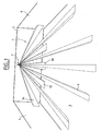
- an infrared radiation detection device 1 has been shown fixed against the upper part and at the mid-length of a wall 2 of a room or a room 3, the two side walls of which can also be seen 4 and 5 perpendicular to this wall 2.
- the wall 2 may in part be glazed and / or have openings or passages.
- the detection device 1 is adapted to present detection or vision fields 6 which are inclined forwards and distributed in the volume of the part 3 in order to detect the presence of intruders in this piece, as well as a series 7 additional detection or vision fields distributed to detect the presence of intruders near the wall 2.
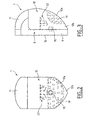
- a radiation detection device 1 comprises a housing 8 which has a parallelepipedal portion 9 whose vertical rear face 10 serves as a support during its attachment and an upper portion 11 projecting in front of the 9.
- the housing 8 is provided with an attached front wall 12 which defines, in front of its portion 9 and below its portion 11, an interior space 13.
- the front wall 12 is, in the vertical direction and in the horizontal direction, curved, its edges along the edges of the portion 9 and the portion 11 of the housing 8.
- the wall 12 is made of a material transparent to infra-red radiation.
- the portion 9 of the housing 8 frontally bears a vertical plate 14, constituted by printed circuit, on which is fixed an optical infrared radiation sensor 15 which has in its front plane 16, in a manner known per se, elements sensitive to a such radiation and differential electronic processing, connected to electronic circuits carried by the plate 14, this sensor having an optical center 17 from which a main axis of vision 18 extending horizontally.
- the front wall 12 has a zone 12a in which is formed a front lens system 19 thus placed in front of and away from the sensor 15 and focusing towards the latter the radiation coming from the detection or vision fields 6 and determining, between the system of lenses 19 and the sensor 15, main focusing fields 20 inscribed in an enveloping volume 21.
- the front wall 12 has a non-focusing zone 12b located between its zone 12a and its edge adjacent to the portion 9 of the housing 8 which is free of lenses and of constant thickness.
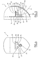
- the radiation detection device 1 further comprises an additional mirror system 22 located laterally and above the enveloping volume 21, in the space 13, whose mirrors focus towards the sensor 15 the radiation coming from the series 7 of the fields additional detection or vision 7 not passing through the lens system 12a and passing through the zone 12b of the front wall 12.
- the structure of the additional system 22 is such that the focusing fields, extending between the mirrors and the sensor 15 and associated with the additional detection or vision fields 7, do not encounter obstacles.
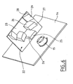
- the additional system 22 comprises, projecting beneath a horizontal plate 23 attached to the vertical plate 14, a central stud 24 whose lower face 25 constitutes a concave central mirror, two secondary studs 26 whose lower face 27 constitutes a concave secondary mirror and two tertiary studs 28 whose lower face 29 constitutes a concave tertiary mirror.
- the central mirror 25 has a vertical plane of symmetry P containing the main axis 18 of the sensor 15.
- the focal length of this central mirror 25 is smaller than that of the lenses of the lens frontal system 19.
- the central mirror 25 is oriented to determine an additional detection or vision field 30 with which a focusing field 31 is associated, this detection or vision field 30 dipping below the detection device, in the vicinity of the wall 2 of the local 3.
- the secondary mirrors 27 are placed symmetrically with respect to the plane of symmetry P and at a distance from this plane. The focal length of these secondary mirrors 27 is greater than that of the central mirror 25.
- the secondary mirrors 27 are oriented to determine additional fields of detection or vision 32 with which are associated focusing fields 33, these detection or vision fields 32 being inclined relative to said plane of symmetry P and extending in the vicinity of the wall 2 of the room 3.
- said detection or vision fields 32 of the secondary mirrors 27 have angular apertures smaller than that of the central mirror 25.
- the tertiary mirrors 29 are placed symmetrically with respect to the plane of symmetry P and at a distance from the plane.
- the focal length of these tertiary mirrors 29 is greater than that of the secondary mirrors 27.
- the tertiary mirrors 29 are oriented to determine additional fields of detection or vision 34 with which are associated focusing fields 35, these detection or vision fields 34 being inclined relative to said plane of symmetry P and extending in the vicinity of the wall 2 of the room 3, at angles of inclination greater than those of the detection or vision fields 32 associated with the secondary mirrors 27.
- said detection or vision fields 32 of the tertiary mirrors 29 have angular apertures smaller than those of the secondary mirrors 27.
- the projections of the detection or vision fields 30, 32 and 34 on the plane P coincide substantially, the projections of these detection or vision fields 30, 32 and 34 on a frontal plane are angularly offset, the projections of the detection fields or vision 34 on a frontal plane forming acute angles with the plane P greater than those of the detection or vision fields 32.
- the arrangement and the orientation of the mirrors 25, 27 and 29 are adapted to focus towards the sensor 15 any infrared radiation from the area located near the wall 2 of the local 3, in addition to the system of lenses 19 which is suitable to focus towards the sensor 15 any infrared radiation from the area of the local 3 located at a distance from the wall 2.
- the choice of different focal lengths of the mirrors 25, 27 and 29, increasing makes it possible to adapt the openings of detection or vision fields, decreasing, at the distance of the monitored locations along the wall 2 with respect to the vertical of the sensor 15, so that the amount of radiant energy from an individual arriving at the sensor 15 can be optimized.
- the room 3 can be completely and properly monitored.
- the pads 24, 26 and 28 are substantially of square or rectangular section and the mirrors 25, 27 and 29 cover their end surfaces.
- the central stud 24 is slightly in front of the front face 16 of the sensor 15.
- the secondary pads 26 are further forward of this front face 16 than the central stud 24 and on either side of the plane P.
- the tertiary studs 29 are even more forward of this front face 16 than the secondary pads 26 and on either side of the plane P, at a distance greater than that of these secondary pads 26.
- the secondary mirrors 27 are further away from the sensor 15 than the central mirror 25 and the tertiary mirrors 29 are further away from the sensor 15 than the secondary mirrors 27.
- the mirrors 25, 27 and 29 are preferably constituted by adapted portions of paraboloids 36, 37 and 38 whose foci are placed at the optical center 17 of the sensor 15, whose axes of revolution 39, 40 and 41 pass through the optical center. 17 of the sensor 15 and are arranged to fix the direction of the corresponding fields of vision or detection 30, 32 and 34 in the desired orientation parallel thereto. They could, however, be constituted by adapted portions of spheres whose focal points would also be placed at the optical center 17 of the sensor 15.
- the present invention is not limited to the example described above. Indeed, the mirrors 25, 27 and 29 could present other Arrangements relative to each other and be made on projecting parts of a single piece fixed on the vertical plate 14 or directly on the housing 8. In addition, other pairs of mirrors could be provided.
Landscapes
- Physics & Mathematics (AREA)
- General Physics & Mathematics (AREA)
- Photometry And Measurement Of Optical Pulse Characteristics (AREA)
- Geophysics And Detection Of Objects (AREA)
Claims (12)
- Vorrichtung zur Detektion von Strahlung, insbesondere Infrarotstrahlung, mit:einem Strahlungsaufnehmer, der an einer Stirnebene mindestens ein für die Strahlung empfindliches Element aufweist und ein optisches Zentrum und eine Hauptsichtachse aufweist, undeinem vor und in einem Abstand zu dem Aufnehmer angeordneten Linsensystem, welches die Strahlung, die von Detektions- oder Sichtfeldern herkommt, die sich vor dem Linsensystem erstrecken, zu dem Aufnehmer fokussiert und welches zwischen dem Linsensystem und dem Aufnehmer Hauptfokussierungsfelder festlegt, die in einem Hüllvolumen angeordnet sind,dadurch gekennzeichnet, daßdie Vorrichtung ferner ein zusätzliches System von Spiegeln aufweist, das neben dem Hüllvolumen (21) angeordnet ist und mindestens zwei Spiegel (25,27; 25,29; 27,29) aufweist, die die von zusätzlichen Detektions- oder Sichtfeldern herkommende, nicht durch das Linsensystem (19) hindurchgehende Strahlung zu dem Aufnehmer (15) hin fokussieren und unterschiedliche Fokuslängen aufweisen, so daß die zusätzlichen Detektions- oder Sichtfelder unterschiedliche Öffnungswinkel aufweisen.
- Detektionsvorrichtung nach Anspruch 1, dadurch gekennzeichnet, daß die mindestens zwei Spiegel zwischen dem Spiegelsystem und dem Aufnehmer zusätzliche Fokussierungsfelder festlegen, deren Projektionen auf die Stirnebene im Winkel zueinander versetzt angeordnet sind.
- Detektionsvorrichtung nach einem der Ansprüche 1 und 2, dadurch gekennzeichnet, daß die mindestens zwei Spiegel zwischen dem Spiegelsystem und dem Aufnehmer zusätzliche Fokussierungsfelder festlegen, deren Projektionen auf eine Ebene, die die Hauptachse aufweist, sich im wesentlichen decken.
- Detektionsvorrichtung nach einem der vorstehenden Ansprüche, dadurch gekennzeichnet, daß das Spiegelsystem aufweist:mindestens einen zentralen Spiegel (25), der eine die Hauptachse enthaltende Symmetrieebene aufweist und ein zentrales Detektions- oder Sichtfeld festlegt, undmindestens einen sekundären Spiegel (27), der eine größere Fokuslänge als der zentrale Spiegel hat und ein bezüglich der Symmetrieebene geneigtes Detektions- oder Sichtfeld festlegt.
- Detektionsvorrichtung nach einem der vorstehenden Ansprüche, dadurch gekennzeichnet, daß das Spiegelsystem aufweist:mindestens einen zentralen Spiegel (25), der eine die Hauptachse enthaltende Symmetrieebene aufweist und ein zentrales Detektions- oder Sichtfeld festlegt, undein Paar von sekundären Spiegeln (27), die symmetrisch zu dieser Symmetrieebene sind, wobei die Fokuslänge dieser sekundären Spiegel größer als diejenige des zentralen Spiegels ist und sekundäre Sichtfelder festlegt, die bezüglich der Symmetrieebene geneigt und symmetrisch sind.
- Detektionsvorrichtung nach Anspruch 5, dadurch gekennzeichnet, daß das Spiegelsystem ferner ein Paar von tertiären Spiegeln (29) aufweist, die symmetrisch bezüglich der Symmetrieebene sind, wobei die Fokuslänge dieser tertiären Spiegel größer als diejenige der sekundären Spiegel ist und Detektions- oder Sichtfelder festlegt, die bezüglich der Symmetrieebene symmetrisch sind und stärker geneigt sind, als die Detektions- oder Sichtfelder der sekundären Spiegel.
- Detektionsvorrichtung nach einem der vorstehenden Ansprüche, dadurch gekennzeichnet, daß die Spiegel an den Endflächen von Vorsprüngen (24,26) eines Stücks gebildet sind.
- Detektionsvorrichtung nach Anspruch 7, dadurch gekennzeichnet, daß die Vorsprünge an einem plattenförmigen Stück angebracht sind.
- Detektionsvorrichtung nach Anspruch 7, dadurch gekennzeichnet, daß die Vorsprünge aus einem einzigen Stück gebildet sind.
- Detektionsvorrichtung nach einem der Ansprüche 7 bis 9, dadurch gekennzeichnet, daß das Stück an einer Platte (14) angebracht ist, die den Strahlungsaufnehmer trägt.
- Detektionsvorrichtung nach einem der vorstehenden Ansprüche, dadurch gekennzeichnet, daß sie ein Gehäuse (8) aufweist, das eine für die Strahlung transparente Wand (12) aufweist, wobei ein Teil (12a) derer das Linsensystem (19) aufweist und ein anderer nicht-fokussierender Teil (12b) derer von den zusätzlichen Sichtfeldern überquert wird.
- Detektionsvorrichtung nach Anspruch 7, dadurch gekennzeichnet, daß die transparente Wand (12) an dem Gehäuse angebracht ist.
Applications Claiming Priority (2)
| Application Number | Priority Date | Filing Date | Title |
|---|---|---|---|
| FR0400532 | 2004-01-21 | ||
| FR0400532A FR2865304B1 (fr) | 2004-01-21 | 2004-01-21 | Dispositif de detection de rayonnement a lentilles et miroirs |
Publications (2)
| Publication Number | Publication Date |
|---|---|
| EP1557805A1 EP1557805A1 (de) | 2005-07-27 |
| EP1557805B1 true EP1557805B1 (de) | 2008-07-02 |
Family
ID=34630655
Family Applications (1)
| Application Number | Title | Priority Date | Filing Date |
|---|---|---|---|
| EP20040293161 Expired - Lifetime EP1557805B1 (de) | 2004-01-21 | 2004-12-29 | Strahlungsdetektor mit Linsen und Spiegeln |
Country Status (3)
| Country | Link |
|---|---|
| EP (1) | EP1557805B1 (de) |
| DE (1) | DE602004014709D1 (de) |
| FR (1) | FR2865304B1 (de) |
Families Citing this family (4)
| Publication number | Priority date | Publication date | Assignee | Title |
|---|---|---|---|---|
| DE102012201423B4 (de) * | 2012-02-01 | 2013-10-31 | Siemens Aktiengesellschaft | Anordnung zur Detektion von Partikeln |
| CN106679827B (zh) * | 2016-11-29 | 2023-07-04 | 美的集团武汉制冷设备有限公司 | 热释电红外传感装置和电器 |
| WO2018209220A1 (en) * | 2017-05-11 | 2018-11-15 | The Trustees Of Princeton University | Binocular vision occupancy detector |
| CN115574948A (zh) * | 2021-07-02 | 2023-01-06 | 杭州海康威视数字技术股份有限公司 | 被动光学探测器 |
Family Cites Families (3)
| Publication number | Priority date | Publication date | Assignee | Title |
|---|---|---|---|---|
| JPS62121523U (de) * | 1986-01-24 | 1987-08-01 | ||
| US4792685A (en) * | 1987-04-29 | 1988-12-20 | Masami Yamakawa | Photoelectric sensor |
| US6346705B1 (en) * | 1999-03-02 | 2002-02-12 | Cordelia Lighting, Inc. | Hidden PIR motion detector with mirrored optics |
-
2004
- 2004-01-21 FR FR0400532A patent/FR2865304B1/fr not_active Expired - Lifetime
- 2004-12-29 EP EP20040293161 patent/EP1557805B1/de not_active Expired - Lifetime
- 2004-12-29 DE DE200460014709 patent/DE602004014709D1/de not_active Expired - Lifetime
Also Published As
| Publication number | Publication date |
|---|---|
| EP1557805A1 (de) | 2005-07-27 |
| FR2865304A1 (fr) | 2005-07-22 |
| DE602004014709D1 (de) | 2008-08-14 |
| FR2865304B1 (fr) | 2006-04-07 |
Similar Documents
| Publication | Publication Date | Title |
|---|---|---|
| CH675170A5 (de) | ||
| FR2962534A1 (fr) | Dispositif de detection pour la detection des conditions environnantes | |
| FR3101468A1 (fr) | Détecteur de fumées | |
| EP2711687B1 (de) | Optischer Gasdetektor | |
| EP1884416A1 (de) | Blockrahmen vor Kraftfahrzeugen | |
| FR2865304A1 (fr) | Dispositif de detection de rayonnement a lentilles et miroirs | |
| WO2020104208A1 (fr) | Partie de véhicule comprenant un dispositif lumineux et une pièce opaque à la lumière visible | |
| FR3056176A1 (fr) | Agencement de fixation d'un ecran de protection d'un dispositif de detection dans un vehicule automobile | |
| FR2524984A1 (fr) | Detecteur optique | |
| FR3111597A1 (fr) | Absorbeur de choc pour parechoc avant de véhicule automobile | |
| WO2009115720A4 (fr) | Detecteur de fumee compact | |
| EP3206469B1 (de) | Halterungsvorrichtung für mindestens zwei leiterplatten, entsprechendes elektronisches modul und entsprechendes elektronisches system | |
| EP2005396A1 (de) | Einrichtung zum zählen und bestimmen der durchgangsrichtung von lebewesen | |
| EP2711686A1 (de) | Optischer Detektor eines Gases | |
| EP1981738B1 (de) | Kotflügelstütze für ein kraftfahrzeug | |
| EP1983495B1 (de) | Rauchmelder mit Vorrichtung an einem Reflektor zum Selektieren eines Lichtstrahles | |
| EP3782139B1 (de) | Optischer rauchdetektor mit streustrahlung | |
| CH662196A5 (fr) | Detecteur de fumee a lumiere diffuse. | |
| EP4229367B1 (de) | Vorrichtung zum zählen von gegenständen | |
| WO2004101916A1 (fr) | Dispositif de protection adapte pour former une palissade autour d’un ouvrage tel qu’une piscine | |
| FR3116148A1 (fr) | Bouton de demande d’arret pour vehicule de transport collectif | |
| FR3129887A1 (fr) | Dispositif fonctionnel d’un véhicule automobile | |
| FR3087930A1 (fr) | Element pour barriere infrarouge reduisant la formation de givre | |
| FR2912503A1 (fr) | Dispositif de detection de temperature | |
| FR3057663A1 (fr) | Boitier avec un capteur pyroelectrique |
Legal Events
| Date | Code | Title | Description |
|---|---|---|---|
| PUAI | Public reference made under article 153(3) epc to a published international application that has entered the european phase |
Free format text: ORIGINAL CODE: 0009012 |
|
| AK | Designated contracting states |
Kind code of ref document: A1 Designated state(s): AT BE BG CH CY CZ DE DK EE ES FI FR GB GR HU IE IS IT LI LT LU MC NL PL PT RO SE SI SK TR |
|
| AX | Request for extension of the european patent |
Extension state: AL BA HR LV MK YU |
|
| 17P | Request for examination filed |
Effective date: 20051212 |
|
| AKX | Designation fees paid |
Designated state(s): DE FR GB IT |
|
| GRAP | Despatch of communication of intention to grant a patent |
Free format text: ORIGINAL CODE: EPIDOSNIGR1 |
|
| GRAS | Grant fee paid |
Free format text: ORIGINAL CODE: EPIDOSNIGR3 |
|
| GRAA | (expected) grant |
Free format text: ORIGINAL CODE: 0009210 |
|
| AK | Designated contracting states |
Kind code of ref document: B1 Designated state(s): DE FR GB IT |
|
| REG | Reference to a national code |
Ref country code: GB Ref legal event code: FG4D Free format text: NOT ENGLISH |
|
| REF | Corresponds to: |
Ref document number: 602004014709 Country of ref document: DE Date of ref document: 20080814 Kind code of ref document: P |
|
| PLBE | No opposition filed within time limit |
Free format text: ORIGINAL CODE: 0009261 |
|
| STAA | Information on the status of an ep patent application or granted ep patent |
Free format text: STATUS: NO OPPOSITION FILED WITHIN TIME LIMIT |
|
| 26N | No opposition filed |
Effective date: 20090403 |
|
| REG | Reference to a national code |
Ref country code: FR Ref legal event code: TP |
|
| REG | Reference to a national code |
Ref country code: FR Ref legal event code: PLFP Year of fee payment: 12 |
|
| REG | Reference to a national code |
Ref country code: FR Ref legal event code: PLFP Year of fee payment: 13 |
|
| REG | Reference to a national code |
Ref country code: FR Ref legal event code: PLFP Year of fee payment: 14 |
|
| PGFP | Annual fee paid to national office [announced via postgrant information from national office to epo] |
Ref country code: GB Payment date: 20221227 Year of fee payment: 19 Ref country code: FR Payment date: 20221227 Year of fee payment: 19 |
|
| PGFP | Annual fee paid to national office [announced via postgrant information from national office to epo] |
Ref country code: IT Payment date: 20221221 Year of fee payment: 19 Ref country code: DE Payment date: 20221228 Year of fee payment: 19 |
|
| REG | Reference to a national code |
Ref country code: DE Ref legal event code: R119 Ref document number: 602004014709 Country of ref document: DE |
|
| GBPC | Gb: european patent ceased through non-payment of renewal fee |
Effective date: 20231229 |
|
| PG25 | Lapsed in a contracting state [announced via postgrant information from national office to epo] |
Ref country code: DE Free format text: LAPSE BECAUSE OF NON-PAYMENT OF DUE FEES Effective date: 20240702 |
|
| PG25 | Lapsed in a contracting state [announced via postgrant information from national office to epo] |
Ref country code: GB Free format text: LAPSE BECAUSE OF NON-PAYMENT OF DUE FEES Effective date: 20231229 |
|
| PG25 | Lapsed in a contracting state [announced via postgrant information from national office to epo] |
Ref country code: FR Free format text: LAPSE BECAUSE OF NON-PAYMENT OF DUE FEES Effective date: 20231231 |
|
| PG25 | Lapsed in a contracting state [announced via postgrant information from national office to epo] |
Ref country code: GB Free format text: LAPSE BECAUSE OF NON-PAYMENT OF DUE FEES Effective date: 20231229 Ref country code: FR Free format text: LAPSE BECAUSE OF NON-PAYMENT OF DUE FEES Effective date: 20231231 Ref country code: DE Free format text: LAPSE BECAUSE OF NON-PAYMENT OF DUE FEES Effective date: 20240702 |
|
| PG25 | Lapsed in a contracting state [announced via postgrant information from national office to epo] |
Ref country code: IT Free format text: LAPSE BECAUSE OF NON-PAYMENT OF DUE FEES Effective date: 20231229 |