EP1557688B1 - Akustisches Messsystem zur Ortung von Rauschquellen - Google Patents
Akustisches Messsystem zur Ortung von Rauschquellen Download PDFInfo
- Publication number
- EP1557688B1 EP1557688B1 EP05356001A EP05356001A EP1557688B1 EP 1557688 B1 EP1557688 B1 EP 1557688B1 EP 05356001 A EP05356001 A EP 05356001A EP 05356001 A EP05356001 A EP 05356001A EP 1557688 B1 EP1557688 B1 EP 1557688B1
- Authority
- EP
- European Patent Office
- Prior art keywords
- microphones
- noise
- groups
- group
- points
- Prior art date
- Legal status (The legal status is an assumption and is not a legal conclusion. Google has not performed a legal analysis and makes no representation as to the accuracy of the status listed.)
- Expired - Lifetime
Links
- 238000005259 measurement Methods 0.000 title claims description 10
- 239000000463 material Substances 0.000 claims abstract description 5
- 239000006260 foam Substances 0.000 claims abstract description 4
- 230000002745 absorbent Effects 0.000 claims abstract description 3
- 239000002250 absorbent Substances 0.000 claims abstract description 3
- 230000001413 cellular effect Effects 0.000 claims abstract description 3
- 238000011282 treatment Methods 0.000 description 6
- 230000010363 phase shift Effects 0.000 description 2
- 230000002860 competitive effect Effects 0.000 description 1
- 238000013016 damping Methods 0.000 description 1
- 238000009413 insulation Methods 0.000 description 1
- 238000011835 investigation Methods 0.000 description 1
- 230000004807 localization Effects 0.000 description 1
- 238000000034 method Methods 0.000 description 1
- 230000005855 radiation Effects 0.000 description 1
Images
Classifications
-
- G—PHYSICS
- G01—MEASURING; TESTING
- G01S—RADIO DIRECTION-FINDING; RADIO NAVIGATION; DETERMINING DISTANCE OR VELOCITY BY USE OF RADIO WAVES; LOCATING OR PRESENCE-DETECTING BY USE OF THE REFLECTION OR RERADIATION OF RADIO WAVES; ANALOGOUS ARRANGEMENTS USING OTHER WAVES
- G01S3/00—Direction-finders for determining the direction from which infrasonic, sonic, ultrasonic, or electromagnetic waves, or particle emission, not having a directional significance, are being received
- G01S3/80—Direction-finders for determining the direction from which infrasonic, sonic, ultrasonic, or electromagnetic waves, or particle emission, not having a directional significance, are being received using ultrasonic, sonic or infrasonic waves
- G01S3/802—Systems for determining direction or deviation from predetermined direction
- G01S3/803—Systems for determining direction or deviation from predetermined direction using amplitude comparison of signals derived from receiving transducers or transducer systems having differently-oriented directivity characteristics
- G01S3/8034—Systems for determining direction or deviation from predetermined direction using amplitude comparison of signals derived from receiving transducers or transducer systems having differently-oriented directivity characteristics wherein the signals are derived simultaneously
- G01S3/8036—Systems for determining direction or deviation from predetermined direction using amplitude comparison of signals derived from receiving transducers or transducer systems having differently-oriented directivity characteristics wherein the signals are derived simultaneously derived directly from separate directional systems
-
- G—PHYSICS
- G03—PHOTOGRAPHY; CINEMATOGRAPHY; ANALOGOUS TECHNIQUES USING WAVES OTHER THAN OPTICAL WAVES; ELECTROGRAPHY; HOLOGRAPHY
- G03H—HOLOGRAPHIC PROCESSES OR APPARATUS
- G03H3/00—Holographic processes or apparatus using ultrasonic, sonic or infrasonic waves for obtaining holograms; Processes or apparatus for obtaining an optical image from them
-
- H—ELECTRICITY
- H04—ELECTRIC COMMUNICATION TECHNIQUE
- H04R—LOUDSPEAKERS, MICROPHONES, GRAMOPHONE PICK-UPS OR LIKE ACOUSTIC ELECTROMECHANICAL TRANSDUCERS; DEAF-AID SETS; PUBLIC ADDRESS SYSTEMS
- H04R1/00—Details of transducers, loudspeakers or microphones
- H04R1/20—Arrangements for obtaining desired frequency or directional characteristics
- H04R1/32—Arrangements for obtaining desired frequency or directional characteristics for obtaining desired directional characteristic only
- H04R1/40—Arrangements for obtaining desired frequency or directional characteristics for obtaining desired directional characteristic only by combining a number of identical transducers
- H04R1/406—Arrangements for obtaining desired frequency or directional characteristics for obtaining desired directional characteristic only by combining a number of identical transducers microphones
-
- H—ELECTRICITY
- H04—ELECTRIC COMMUNICATION TECHNIQUE
- H04R—LOUDSPEAKERS, MICROPHONES, GRAMOPHONE PICK-UPS OR LIKE ACOUSTIC ELECTROMECHANICAL TRANSDUCERS; DEAF-AID SETS; PUBLIC ADDRESS SYSTEMS
- H04R2201/00—Details of transducers, loudspeakers or microphones covered by H04R1/00 but not provided for in any of its subgroups
- H04R2201/40—Details of arrangements for obtaining desired directional characteristic by combining a number of identical transducers covered by H04R1/40 but not provided for in any of its subgroups
- H04R2201/401—2D or 3D arrays of transducers
Definitions
- the present invention relates to an acoustic measurement system for locating sources of noise and measuring their intensity.
- a known device comprises several omnidirectional microphones, for example 24 in number, arranged on a plane.
- the plane on which the microphones are located is oriented substantially perpendicular to the presumed direction of the noise source.
- the microphones measure the sound pressure resulting from the noise emission, and each provide a signal to a processing device. This processing device makes it possible to obtain a hologram of the sources of noise.
- the hologram of the noise sources is obtained by performing calculations at different points, the microphones measuring the acoustic pressure for each of the points, taking into account the phase shift of the distances of the different microphones vis-à-vis the different points of measurement.
- these devices are suitable for external noise measurements, for example to measure the sound of a motor bench, they are faulted as soon as they are placed inside a cabin, because they do not know how to distinguish the waves that arrive in front of or behind the antenna constituted by all the microphones.
- the hologram of the noise sources is obtained by performing calculations at different points, the microphones measuring the sound pressure for each of the points, taking into account the phase shift of the distances of the different microphones vis-à-vis the different measuring points.
- JP 04 072525 discloses an acoustic measurement system of the prior art.
- the technical problem underlying the invention is to provide a system that allows the precise and simple localization of noise sources inside an enclosure.
- the system it concerns comprises a plurality of microphones oriented in several directions and mounted in a support so that each is flush with a rigid surface, the different microphones being connected to a signal processing device.
- Each microphone "sees” especially the noise sources placed opposite, the rigid body acting as a screen for noise sources placed behind the rigid body, relative to the microphone considered.
- the microphones support is coated with an absorbent material, such as a cellular foam.
- the support of the microphones is constituted by a sphere.
- the different microphones are distributed on the surface of the sphere.
- the sphere has the advantage that it is a natural form whose behavior is easy to model. For a given source position, the module and the phase of the sound pressure measured by each microphone can be calculated for each frequency.
- the microphones support is constituted by two parallel disks interconnected by a portion of the toric surface, the microphones being placed in the disks.
- This second embodiment has the advantage of separating the two half spaces.
- the rigid support which may have for example the shape of an ellipsoid or a parallelepiped.
- the measurement system according to the invention consists, for each group of microphones, of processing the signals coming from these microphones, in order to provide a hologram of the sources of noise, that is to say a distribution of the acoustic pressures or intensities. different points of the same surface.
- the system according to the invention consists, before performing a measurement, to distribute a number of microphones belonging to one or two supports, in two groups.
- This distribution of a certain number of microphones belonging to one or two supports, in two groups, makes it possible to perform for the two groups of microphones a differential treatment of the signals coming from the different microphones of the two groups.
- This differential treatment may represent the functioning of the human ear.
- this system consists in performing a focusing treatment for each group of microphones at each point where it is desired to know if there is a source of noise, then to perform for each calculation point the difference between the focused signals of the two groups, this difference being zero when the calculation point corresponds to the location of the noise source.
- this system consists in performing a focus processing for a group of microphones at different points situated on the side of this group, in order to determine the existence of noise sources at these points, and performing, for the other group of microphones, focusing processing at opposite points of the first and then performing for each group of two points the difference between the focused signals of the two groups, this difference being maximum when the calculation point corresponds to the location of the noise source.
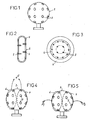
- the figure 1 represents a sphere 2 made of rigid material, and whose outer surface may be coated with a damping material, such as foam, or can be perforated. Inside the sphere 2 are mounted 24 microphones 3, each of which is flush with the surface of the sphere 2.
- FIG. 2 and 3 represent an alternative embodiment of this system in which the rigid body has a different shape, and is constituted by two flat discs 4 interconnected by a torus portion 5. As shown in FIG. figure 3 the microphones 3 are flush with the surfaces of the two disks. This realization has the advantage of separating the two half spaces.
- the Figures 4 and 5 represent the device of figure 1 , that is to say a sphere 2 equipped with a certain number of microphones, in this case 24. Some microphones are associated to form a group 6, while other microphones are associated to form a group 7. It should be noted that the groups 6 and 7 do not necessarily contain all the microphones of the sphere 2. It should also be noted that this grouping is a virtual group and not a physical one, this grouping being realized in the processing of the signals received by the different microphones of the two groups 6 and 7.
- the Figures 4 and 5 represent the implementation of a so-called differential processing.
- the processing makes it possible to estimate the position of the maximum noise source.
- a differential estimator For each point where you want to know if there is a source of noise, you need to calculate a differential estimator as follows. First of all, a focusing treatment is performed for the same calculation point C for the two groups 6 and 7 of microphones. The difference function of the two results of the groups of microphones is calculated. This calculation is repeated for all the points where one wishes to know if there is a source. In the embodiment shown in figure 4 the focus is on the same point C for the two groups 6 and 7, and the difference function is minimal, when the calculation point C is located at the position of the noise source.
- the figure 5 represents an execution variant in which the same elements are designated by the same references as before.
- a focusing treatment is performed for the group 6 of microphones, at a point P1 which is the point which is searched for if it corresponds to the source of noise, while the focus for the microphones of the group 7 is performed at a point P2 located on the opposite side to point P1.
- the difference function between the two focusing results is calculated.
- the difference function is maximum when the calculation point P1 is located at the position of the actual source of noise.
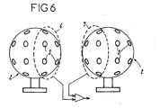
- the figure 6 represents an alternative embodiment in which the groups 6 and 7 of microphones 3 belong to two distinct spheres 2.
- the invention provides a great improvement to the existing technique by providing a simple structure device for determining the location of a noise source and measuring its intensity, including the interior of a cabin distinguishing the waves that arrive in front of or behind the antenna formed by different microphones, and providing a signal processing mode further improving the conditions of location of a source of noise.
- the invention is not limited to the embodiments of this system, described above as an example, it encompasses all variants.
- the rigid support of the microphones could have a different shape, for example a parallelepipedal shape, or the signal processing might not include differential processing, but the simple realization of a hologram in a manner known in the art. itself, without departing from the scope of the invention.
Landscapes
- Physics & Mathematics (AREA)
- Engineering & Computer Science (AREA)
- General Physics & Mathematics (AREA)
- Health & Medical Sciences (AREA)
- Otolaryngology (AREA)
- Radar, Positioning & Navigation (AREA)
- Remote Sensing (AREA)
- Acoustics & Sound (AREA)
- Signal Processing (AREA)
- Measurement Of Mechanical Vibrations Or Ultrasonic Waves (AREA)
- Measurement Of Velocity Or Position Using Acoustic Or Ultrasonic Waves (AREA)
Claims (8)
- Akustisches Messsystem, das es ermöglich, Geräuschquellen zu lokalisieren und ihre Stärke zu messen, mit mehreren Mikrophonen (3), die in mehrere Richtungen ausgerichtet und in einen Träger (2) montiert sind, wobei die verschiedenen Mikrophone (3) mit einer Signalverarbeitungseinrichtung verbunden sind, dadurch gekennzeichnet, dass die Mikrophone (3) so montiert sind, dass jedes mit einer steifen Fläche auf gleicher Höhe liegt, und dass die Signalverarbeitungseinrichtung geeignet ist, um von diesen Mikrophonen (3) stammende Signale durch Fokussierung zu verarbeiten, um ein Hologramm der Geräuschquellen, d.h. eine Verteilung der Schalldrücke oder -stärken an verschiedenen Punkten der gleichen Fläche, zu liefern.
- System nach Anspruch 1, dadurch gekennzeichnet, dass der Träger (2) der Mikrophone (3) mit einem absorbierenden Werkstoff wie einem Schaumstoff verkleidet ist.
- System nach einem der Ansprüche 1 und 2, dadurch gekennzeichnet, dass der Träger der Mikrophone aus einer Kugel (2) besteht.
- System nach einem der Ansprüche 1 und 2, dadurch gekennzeichnet, dass der Träger der Mikrophone aus zwei parallelen Scheiben (4) besteht, die miteinander über einen ringförmigen Flächenabschnitt (5) verbunden sind, wobei die Mikrophone (3) in den Scheiben (4) angeordnet sind.
- System nach einem der Ansprüche 1 bis 4, dadurch gekennzeichnet, dass es vor der Durchführung einer Messung darin besteht, eine bestimmte Anzahl von Mikrophonen (3), die zu einem oder zwei Trägern (2) gehören, in zwei Gruppen (6, 7) aufzuteilen.
- System nach Anspruch 5, dadurch gekennzeichnet, dass es darin besteht, für die zwei Gruppen (6, 7) von Mikrophonen eine differenzielle Verarbeitung der von den verschiedenen Mikrophonen (3) der zwei Gruppen stammenden Signale durchzuführen.
- System nach Anspruch 6, dadurch gekennzeichnet, dass es darin besteht, eine Fokussierungsverarbeitung für jede Gruppe (6, 7) von Mikrophonen (3) an jedem Punkt (C) durchzuführen, wo man wissen möchte, ob es eine Geräuschquelle gibt, dann für jeden Berechnungspunkt die Differenz zwischen den fokussierten Signalen der zwei Gruppen (6, 7), zu berechnen, wobei diese Differenz Null ist, wenn der Berechnungspunkt (C) dem Ort der Geräuschquelle entspricht.
- System nach Anspruch 6, dadurch gekennzeichnet, dass es darin besteht, eine Fokussierungsverarbeitung für eine Gruppe (6, 7) von Mikrophonen (3) an verschiedenen Punkten (P1) durchzuführen, die sich auf der Seite dieser Gruppe (6) befinden, um das Vorhandensein von Geräuschquellen an diesen verschiedenen Punkten zu bestimmen, und für die andere Gruppe (7) von Mikrophonen (3) eine Fokussierungsverarbeitung an den ersten entgegengesetzten Punkten (P2) durchzuführen, dann für jede Gruppe (6, 7) von zwei Punkten die Differenz zwischen den fokussierten Signalen der zwei Gruppen zu berechnen, wobei diese Differenz maximal ist, wenn der Berechnungspunkt dem Ort der Geräuschquelle entspricht.
Applications Claiming Priority (2)
| Application Number | Priority Date | Filing Date | Title |
|---|---|---|---|
| FR0400202 | 2004-01-09 | ||
| FR0400202A FR2865040B1 (fr) | 2004-01-09 | 2004-01-09 | Systeme de mesure acoustique permettant de localiser des sources de bruit |
Publications (2)
| Publication Number | Publication Date |
|---|---|
| EP1557688A1 EP1557688A1 (de) | 2005-07-27 |
| EP1557688B1 true EP1557688B1 (de) | 2009-04-08 |
Family
ID=34630641
Family Applications (1)
| Application Number | Title | Priority Date | Filing Date |
|---|---|---|---|
| EP05356001A Expired - Lifetime EP1557688B1 (de) | 2004-01-09 | 2005-01-03 | Akustisches Messsystem zur Ortung von Rauschquellen |
Country Status (6)
| Country | Link |
|---|---|
| US (1) | US7817804B2 (de) |
| EP (1) | EP1557688B1 (de) |
| AT (1) | ATE428121T1 (de) |
| DE (1) | DE602005013708D1 (de) |
| DK (1) | DK1557688T3 (de) |
| FR (1) | FR2865040B1 (de) |
Families Citing this family (11)
| Publication number | Priority date | Publication date | Assignee | Title |
|---|---|---|---|---|
| US8090117B2 (en) * | 2005-03-16 | 2012-01-03 | James Cox | Microphone array and digital signal processing system |
| FR2896314B1 (fr) * | 2006-01-18 | 2008-02-22 | Microdb Sa | Dispositif de localisation de sources acoustiques et de mesure de leur intensite |
| FR2899341B1 (fr) * | 2006-03-29 | 2008-06-20 | Microdb Sa | Dispositif de localisation acoustique et de mesure de leur intensite |
| WO2008042884A1 (en) * | 2006-10-02 | 2008-04-10 | Wayne State University | Locating arbitrary noise sources |
| SE534042C2 (sv) * | 2009-08-19 | 2011-04-12 | Scania Cv Ab | Metod och anordning för att simulera akustiska emissioner från en motor |
| FR2971341B1 (fr) | 2011-02-04 | 2014-01-24 | Microdb | Dispositif de localisation acoustique |
| GB201321852D0 (en) * | 2013-12-10 | 2014-01-22 | Thales Holdings Uk Plc | Acoustic Detector |
| CN104571492B (zh) * | 2014-10-10 | 2017-12-05 | 上海大学 | 一种虚拟现实声渲染中球面声源表面的位置分布方法 |
| US10337757B2 (en) * | 2016-08-31 | 2019-07-02 | The Boeing Company | In-duct acoustic measuring apparatus and method |
| NO20211439A1 (no) * | 2021-11-26 | 2023-05-29 | Momentum Tech As | Støykartleggingsinnretning |
| CN115027675B (zh) * | 2022-06-21 | 2023-05-19 | 江汉大学 | 一种基于无人机平台用爆破现场噪声测量装置 |
Family Cites Families (8)
| Publication number | Priority date | Publication date | Assignee | Title |
|---|---|---|---|---|
| US4332979A (en) * | 1978-12-19 | 1982-06-01 | Fischer Mark L | Electronic environmental acoustic simulator |
| US6310832B1 (en) * | 1982-11-17 | 2001-10-30 | Raytheon Company | Interpolated beamforming tracker |
| JPH0472525A (ja) | 1990-07-13 | 1992-03-06 | Nippon Telegr & Teleph Corp <Ntt> | 音源方向識別センサ |
| JP3789685B2 (ja) * | 1999-07-02 | 2006-06-28 | 富士通株式会社 | マイクロホンアレイ装置 |
| JP2001166025A (ja) * | 1999-12-14 | 2001-06-22 | Matsushita Electric Ind Co Ltd | 音源の方向推定方法および収音方法およびその装置 |
| JP4722347B2 (ja) * | 2000-10-02 | 2011-07-13 | 中部電力株式会社 | 音源探査システム |
| US7248703B1 (en) * | 2001-06-26 | 2007-07-24 | Bbn Technologies Corp. | Systems and methods for adaptive noise cancellation |
| US20030147539A1 (en) * | 2002-01-11 | 2003-08-07 | Mh Acoustics, Llc, A Delaware Corporation | Audio system based on at least second-order eigenbeams |
-
2004
- 2004-01-09 FR FR0400202A patent/FR2865040B1/fr not_active Expired - Fee Related
-
2005
- 2005-01-03 DK DK05356001T patent/DK1557688T3/da active
- 2005-01-03 DE DE602005013708T patent/DE602005013708D1/de not_active Expired - Lifetime
- 2005-01-03 EP EP05356001A patent/EP1557688B1/de not_active Expired - Lifetime
- 2005-01-03 AT AT05356001T patent/ATE428121T1/de not_active IP Right Cessation
- 2005-01-04 US US11/027,939 patent/US7817804B2/en not_active Expired - Fee Related
Also Published As
| Publication number | Publication date |
|---|---|
| FR2865040B1 (fr) | 2006-05-05 |
| US7817804B2 (en) | 2010-10-19 |
| ATE428121T1 (de) | 2009-04-15 |
| US20050163330A1 (en) | 2005-07-28 |
| DE602005013708D1 (de) | 2009-05-20 |
| EP1557688A1 (de) | 2005-07-27 |
| DK1557688T3 (da) | 2009-08-03 |
| FR2865040A1 (fr) | 2005-07-15 |
Similar Documents
| Publication | Publication Date | Title |
|---|---|---|
| EP1557688B1 (de) | Akustisches Messsystem zur Ortung von Rauschquellen | |
| Jaeger et al. | Effect of surface treatment on array microphone self-noise | |
| CA2318378C (fr) | Transducteur ultrasonore de contact, a elements multiples | |
| US7266044B2 (en) | Method and apparatus for acoustic source tracking using a horizontal line array | |
| EP0150634B1 (de) | Ultraschallwandler für Echographie mit einer eine convexe Oberfläche formende Matrix von Wandlerelementen | |
| EP2100161B1 (de) | Verfahren zur mehrwege-passivradar-verarbeitung eines fm-gelegenheitssignals | |
| FR2749938A1 (fr) | Procede et dispositif de detection et de localisation de source sonore reflechissante | |
| EP0416992A1 (de) | Lineare hydrophonische Antenne und dazugehörende elektronische Vorrichtung zum Aufheben der links-rechts Zweideutigkeit | |
| FR2790102A1 (fr) | Procede de traitement de jeux de donnees sismiques | |
| EP3785026B1 (de) | Verfahren und system zur zerstörungsfreien prüfung eines mechanischen bauteils | |
| EP0733408B1 (de) | Ultraschallsensor und Messverfahren unter Verwendung eines derartigen Sensors | |
| Dall'Osto et al. | Measurement of acoustic particle motion in shallow water and its application to geoacoustic inversion | |
| EP2018579B1 (de) | Verbesserter frontalsonar | |
| FR2845510A1 (fr) | Installation et procede de mesure acoustique par microphone repere dans l'espace | |
| FR2525774A1 (fr) | Dispositif de filtrage adaptatif de signaux recus par un sonar actif pour la rejection de la reverberation | |
| EP2485062A2 (de) | Schallortungsvorrichtung | |
| FR2590679A1 (fr) | Procede de determination passive de donnees de reperage d'un vehicule | |
| FR3017708A1 (fr) | Dispositif de mesure acoustique dans un ecoulement d'air | |
| EP2182334B1 (de) | Vorrichtung zum Messen und Darstellen der Geräuschquellen innerhalb eines Raums | |
| FR2988173A1 (fr) | Dispositif de sondage a ultrasons multicapteurs et procede de fabrication d'un tel dispositif, procede de commande de capteurs d'une sonde a ultrasons et programme d'ordinateur correspondant | |
| FR2896314A1 (fr) | Dispositif de localisation de sources acoustiques et de mesure de leur intensite | |
| Gerges et al. | State of the art beamforming software and hardware for applications | |
| Dreier et al. | Speed-dependent directivity patterns of road-traffic vehicles | |
| Brusniak et al. | Phased array measurements of full-scale engine exhaust noise | |
| To et al. | Power estimation of sound sources on low-speed electric trains using a deconvolution approach |
Legal Events
| Date | Code | Title | Description |
|---|---|---|---|
| PUAI | Public reference made under article 153(3) epc to a published international application that has entered the european phase |
Free format text: ORIGINAL CODE: 0009012 |
|
| AK | Designated contracting states |
Kind code of ref document: A1 Designated state(s): AT BE BG CH CY CZ DE DK EE ES FI FR GB GR HU IE IS IT LI LT LU MC NL PL PT RO SE SI SK TR |
|
| AX | Request for extension of the european patent |
Extension state: AL BA HR LV MK YU |
|
| 17P | Request for examination filed |
Effective date: 20051219 |
|
| AKX | Designation fees paid |
Designated state(s): AT BE BG CH CY CZ DE DK EE ES FI FR GB GR HU IE IS IT LI LT LU MC NL PL PT RO SE SI SK TR |
|
| GRAP | Despatch of communication of intention to grant a patent |
Free format text: ORIGINAL CODE: EPIDOSNIGR1 |
|
| GRAS | Grant fee paid |
Free format text: ORIGINAL CODE: EPIDOSNIGR3 |
|
| GRAA | (expected) grant |
Free format text: ORIGINAL CODE: 0009210 |
|
| AK | Designated contracting states |
Kind code of ref document: B1 Designated state(s): AT BE BG CH CY CZ DE DK EE ES FI FR GB GR HU IE IS IT LI LT LU MC NL PL PT RO SE SI SK TR |
|
| REG | Reference to a national code |
Ref country code: GB Ref legal event code: FG4D Free format text: NOT ENGLISH |
|
| REG | Reference to a national code |
Ref country code: CH Ref legal event code: EP |
|
| REG | Reference to a national code |
Ref country code: IE Ref legal event code: FG4D |
|
| REF | Corresponds to: |
Ref document number: 602005013708 Country of ref document: DE Date of ref document: 20090520 Kind code of ref document: P |
|
| PG25 | Lapsed in a contracting state [announced via postgrant information from national office to epo] |
Ref country code: SI Free format text: LAPSE BECAUSE OF FAILURE TO SUBMIT A TRANSLATION OF THE DESCRIPTION OR TO PAY THE FEE WITHIN THE PRESCRIBED TIME-LIMIT Effective date: 20090408 |
|
| REG | Reference to a national code |
Ref country code: DK Ref legal event code: T3 |
|
| REG | Reference to a national code |
Ref country code: SE Ref legal event code: TRGR |
|
| NLV1 | Nl: lapsed or annulled due to failure to fulfill the requirements of art. 29p and 29m of the patents act | ||
| REG | Reference to a national code |
Ref country code: IE Ref legal event code: FD4D |
|
| PG25 | Lapsed in a contracting state [announced via postgrant information from national office to epo] |
Ref country code: LT Free format text: LAPSE BECAUSE OF FAILURE TO SUBMIT A TRANSLATION OF THE DESCRIPTION OR TO PAY THE FEE WITHIN THE PRESCRIBED TIME-LIMIT Effective date: 20090408 Ref country code: FI Free format text: LAPSE BECAUSE OF FAILURE TO SUBMIT A TRANSLATION OF THE DESCRIPTION OR TO PAY THE FEE WITHIN THE PRESCRIBED TIME-LIMIT Effective date: 20090408 Ref country code: ES Free format text: LAPSE BECAUSE OF FAILURE TO SUBMIT A TRANSLATION OF THE DESCRIPTION OR TO PAY THE FEE WITHIN THE PRESCRIBED TIME-LIMIT Effective date: 20090719 Ref country code: AT Free format text: LAPSE BECAUSE OF FAILURE TO SUBMIT A TRANSLATION OF THE DESCRIPTION OR TO PAY THE FEE WITHIN THE PRESCRIBED TIME-LIMIT Effective date: 20090408 Ref country code: PT Free format text: LAPSE BECAUSE OF FAILURE TO SUBMIT A TRANSLATION OF THE DESCRIPTION OR TO PAY THE FEE WITHIN THE PRESCRIBED TIME-LIMIT Effective date: 20090908 |
|
| PG25 | Lapsed in a contracting state [announced via postgrant information from national office to epo] |
Ref country code: PL Free format text: LAPSE BECAUSE OF FAILURE TO SUBMIT A TRANSLATION OF THE DESCRIPTION OR TO PAY THE FEE WITHIN THE PRESCRIBED TIME-LIMIT Effective date: 20090408 Ref country code: IS Free format text: LAPSE BECAUSE OF FAILURE TO SUBMIT A TRANSLATION OF THE DESCRIPTION OR TO PAY THE FEE WITHIN THE PRESCRIBED TIME-LIMIT Effective date: 20090808 Ref country code: NL Free format text: LAPSE BECAUSE OF FAILURE TO SUBMIT A TRANSLATION OF THE DESCRIPTION OR TO PAY THE FEE WITHIN THE PRESCRIBED TIME-LIMIT Effective date: 20090408 |
|
| PG25 | Lapsed in a contracting state [announced via postgrant information from national office to epo] |
Ref country code: EE Free format text: LAPSE BECAUSE OF FAILURE TO SUBMIT A TRANSLATION OF THE DESCRIPTION OR TO PAY THE FEE WITHIN THE PRESCRIBED TIME-LIMIT Effective date: 20090408 Ref country code: IE Free format text: LAPSE BECAUSE OF FAILURE TO SUBMIT A TRANSLATION OF THE DESCRIPTION OR TO PAY THE FEE WITHIN THE PRESCRIBED TIME-LIMIT Effective date: 20090408 Ref country code: CZ Free format text: LAPSE BECAUSE OF FAILURE TO SUBMIT A TRANSLATION OF THE DESCRIPTION OR TO PAY THE FEE WITHIN THE PRESCRIBED TIME-LIMIT Effective date: 20090408 Ref country code: RO Free format text: LAPSE BECAUSE OF FAILURE TO SUBMIT A TRANSLATION OF THE DESCRIPTION OR TO PAY THE FEE WITHIN THE PRESCRIBED TIME-LIMIT Effective date: 20090408 |
|
| PLBE | No opposition filed within time limit |
Free format text: ORIGINAL CODE: 0009261 |
|
| STAA | Information on the status of an ep patent application or granted ep patent |
Free format text: STATUS: NO OPPOSITION FILED WITHIN TIME LIMIT |
|
| PG25 | Lapsed in a contracting state [announced via postgrant information from national office to epo] |
Ref country code: SK Free format text: LAPSE BECAUSE OF FAILURE TO SUBMIT A TRANSLATION OF THE DESCRIPTION OR TO PAY THE FEE WITHIN THE PRESCRIBED TIME-LIMIT Effective date: 20090408 |
|
| 26N | No opposition filed |
Effective date: 20100111 |
|
| PG25 | Lapsed in a contracting state [announced via postgrant information from national office to epo] |
Ref country code: BG Free format text: LAPSE BECAUSE OF FAILURE TO SUBMIT A TRANSLATION OF THE DESCRIPTION OR TO PAY THE FEE WITHIN THE PRESCRIBED TIME-LIMIT Effective date: 20090708 |
|
| BERE | Be: lapsed |
Owner name: AIRBUS FRANCE Effective date: 20100131 Owner name: MICRODB Effective date: 20100131 |
|
| PG25 | Lapsed in a contracting state [announced via postgrant information from national office to epo] |
Ref country code: MC Free format text: LAPSE BECAUSE OF NON-PAYMENT OF DUE FEES Effective date: 20100131 |
|
| REG | Reference to a national code |
Ref country code: CH Ref legal event code: PL |
|
| PG25 | Lapsed in a contracting state [announced via postgrant information from national office to epo] |
Ref country code: GR Free format text: LAPSE BECAUSE OF FAILURE TO SUBMIT A TRANSLATION OF THE DESCRIPTION OR TO PAY THE FEE WITHIN THE PRESCRIBED TIME-LIMIT Effective date: 20090709 Ref country code: LI Free format text: LAPSE BECAUSE OF NON-PAYMENT OF DUE FEES Effective date: 20100131 Ref country code: CH Free format text: LAPSE BECAUSE OF NON-PAYMENT OF DUE FEES Effective date: 20100131 |
|
| PG25 | Lapsed in a contracting state [announced via postgrant information from national office to epo] |
Ref country code: BE Free format text: LAPSE BECAUSE OF NON-PAYMENT OF DUE FEES Effective date: 20100131 |
|
| REG | Reference to a national code |
Ref country code: GB Ref legal event code: 732E Free format text: REGISTERED BETWEEN 20110721 AND 20110727 |
|
| REG | Reference to a national code |
Ref country code: DE Ref legal event code: R082 Ref document number: 602005013708 Country of ref document: DE Representative=s name: PATENTANWAELTE MAGENBAUER & KOLLEGEN, DE |
|
| REG | Reference to a national code |
Ref country code: FR Ref legal event code: CD Owner name: AIRBUS OPERATIONS, FR Effective date: 20120313 Ref country code: FR Ref legal event code: CA Effective date: 20120313 Ref country code: FR Ref legal event code: CJ Effective date: 20120313 |
|
| REG | Reference to a national code |
Ref country code: DE Ref legal event code: R082 Ref document number: 602005013708 Country of ref document: DE Representative=s name: PATENTANWAELTE MAGENBAUER & KOLLEGEN PARTNERSC, DE Effective date: 20120326 Ref country code: DE Ref legal event code: R081 Ref document number: 602005013708 Country of ref document: DE Owner name: AIRBUS OPERATIONS SAS, FR Free format text: FORMER OWNER: MICRODB, AIRBUS FRANCE, , FR Effective date: 20120326 Ref country code: DE Ref legal event code: R081 Ref document number: 602005013708 Country of ref document: DE Owner name: MICRODB, FR Free format text: FORMER OWNER: MICRODB, AIRBUS FRANCE, , FR Effective date: 20120326 Ref country code: DE Ref legal event code: R082 Ref document number: 602005013708 Country of ref document: DE Representative=s name: PATENTANWAELTE MAGENBAUER & KOLLEGEN, DE Effective date: 20120326 Ref country code: DE Ref legal event code: R081 Ref document number: 602005013708 Country of ref document: DE Owner name: MICRODB, FR Free format text: FORMER OWNERS: MICRODB, ECULLY, FR; AIRBUS FRANCE, TOULOUSE, FR Effective date: 20120326 Ref country code: DE Ref legal event code: R081 Ref document number: 602005013708 Country of ref document: DE Owner name: AIRBUS OPERATIONS SAS, FR Free format text: FORMER OWNERS: MICRODB, ECULLY, FR; AIRBUS FRANCE, TOULOUSE, FR Effective date: 20120326 |
|
| PG25 | Lapsed in a contracting state [announced via postgrant information from national office to epo] |
Ref country code: CY Free format text: LAPSE BECAUSE OF FAILURE TO SUBMIT A TRANSLATION OF THE DESCRIPTION OR TO PAY THE FEE WITHIN THE PRESCRIBED TIME-LIMIT Effective date: 20090408 |
|
| PG25 | Lapsed in a contracting state [announced via postgrant information from national office to epo] |
Ref country code: HU Free format text: LAPSE BECAUSE OF FAILURE TO SUBMIT A TRANSLATION OF THE DESCRIPTION OR TO PAY THE FEE WITHIN THE PRESCRIBED TIME-LIMIT Effective date: 20091009 Ref country code: LU Free format text: LAPSE BECAUSE OF NON-PAYMENT OF DUE FEES Effective date: 20100103 |
|
| PG25 | Lapsed in a contracting state [announced via postgrant information from national office to epo] |
Ref country code: TR Free format text: LAPSE BECAUSE OF FAILURE TO SUBMIT A TRANSLATION OF THE DESCRIPTION OR TO PAY THE FEE WITHIN THE PRESCRIBED TIME-LIMIT Effective date: 20090408 |
|
| REG | Reference to a national code |
Ref country code: FR Ref legal event code: TP Owner name: AIRBUS HOLDING, FR Effective date: 20130322 |
|
| REG | Reference to a national code |
Ref country code: FR Ref legal event code: PLFP Year of fee payment: 12 |
|
| REG | Reference to a national code |
Ref country code: FR Ref legal event code: PLFP Year of fee payment: 13 |
|
| REG | Reference to a national code |
Ref country code: FR Ref legal event code: PLFP Year of fee payment: 14 |
|
| PGFP | Annual fee paid to national office [announced via postgrant information from national office to epo] |
Ref country code: GB Payment date: 20180119 Year of fee payment: 14 Ref country code: DE Payment date: 20180122 Year of fee payment: 14 Ref country code: DK Payment date: 20180119 Year of fee payment: 14 |
|
| PGFP | Annual fee paid to national office [announced via postgrant information from national office to epo] |
Ref country code: IT Payment date: 20180129 Year of fee payment: 14 Ref country code: SE Payment date: 20180119 Year of fee payment: 14 Ref country code: FR Payment date: 20180119 Year of fee payment: 14 |
|
| REG | Reference to a national code |
Ref country code: DE Ref legal event code: R119 Ref document number: 602005013708 Country of ref document: DE |
|
| REG | Reference to a national code |
Ref country code: DK Ref legal event code: EBP Effective date: 20190131 |
|
| GBPC | Gb: european patent ceased through non-payment of renewal fee |
Effective date: 20190103 |
|
| PG25 | Lapsed in a contracting state [announced via postgrant information from national office to epo] |
Ref country code: FR Free format text: LAPSE BECAUSE OF NON-PAYMENT OF DUE FEES Effective date: 20190131 Ref country code: DE Free format text: LAPSE BECAUSE OF NON-PAYMENT OF DUE FEES Effective date: 20190801 Ref country code: SE Free format text: LAPSE BECAUSE OF NON-PAYMENT OF DUE FEES Effective date: 20190104 |
|
| PG25 | Lapsed in a contracting state [announced via postgrant information from national office to epo] |
Ref country code: GB Free format text: LAPSE BECAUSE OF NON-PAYMENT OF DUE FEES Effective date: 20190103 |
|
| PG25 | Lapsed in a contracting state [announced via postgrant information from national office to epo] |
Ref country code: DK Free format text: LAPSE BECAUSE OF NON-PAYMENT OF DUE FEES Effective date: 20190131 |
|
| PG25 | Lapsed in a contracting state [announced via postgrant information from national office to epo] |
Ref country code: IT Free format text: LAPSE BECAUSE OF NON-PAYMENT OF DUE FEES Effective date: 20190103 |