EP1557643B1 - Capteur d'angle de rotation - Google Patents
Capteur d'angle de rotation Download PDFInfo
- Publication number
- EP1557643B1 EP1557643B1 EP05000439A EP05000439A EP1557643B1 EP 1557643 B1 EP1557643 B1 EP 1557643B1 EP 05000439 A EP05000439 A EP 05000439A EP 05000439 A EP05000439 A EP 05000439A EP 1557643 B1 EP1557643 B1 EP 1557643B1
- Authority
- EP
- European Patent Office
- Prior art keywords
- attachment
- rotation angle
- measurement device
- lugs
- rotary encoder
- Prior art date
- Legal status (The legal status is an assumption and is not a legal conclusion. Google has not performed a legal analysis and makes no representation as to the accuracy of the status listed.)
- Expired - Lifetime
Links
- 230000008878 coupling Effects 0.000 claims abstract description 21
- 238000010168 coupling process Methods 0.000 claims abstract description 21
- 238000005859 coupling reaction Methods 0.000 claims abstract description 21
- 238000005259 measurement Methods 0.000 claims description 13
- 229910000639 Spring steel Inorganic materials 0.000 claims description 4
- 230000006835 compression Effects 0.000 claims description 2
- 238000007906 compression Methods 0.000 claims description 2
- 230000001419 dependent effect Effects 0.000 claims 1
- 239000013013 elastic material Substances 0.000 claims 1
- 238000009434 installation Methods 0.000 description 3
- 239000012858 resilient material Substances 0.000 description 2
- 230000001133 acceleration Effects 0.000 description 1
- 238000005452 bending Methods 0.000 description 1
- 238000010276 construction Methods 0.000 description 1
- 238000000034 method Methods 0.000 description 1
- 239000013589 supplement Substances 0.000 description 1
Images

Classifications
-
- G—PHYSICS
- G01—MEASURING; TESTING
- G01D—MEASURING NOT SPECIALLY ADAPTED FOR A SPECIFIC VARIABLE; ARRANGEMENTS FOR MEASURING TWO OR MORE VARIABLES NOT COVERED IN A SINGLE OTHER SUBCLASS; TARIFF METERING APPARATUS; MEASURING OR TESTING NOT OTHERWISE PROVIDED FOR
- G01D11/00—Component parts of measuring arrangements not specially adapted for a specific variable
- G01D11/30—Supports specially adapted for an instrument; Supports specially adapted for a set of instruments
Definitions
- the invention relates to a rotational angle measuring device according to the preamble of claim 1.
- Such a rotational angle measuring device is known from DE 102 16 376 A1, the content of which supplements the disclosure content of the present application by this reference.
- the known rotation angle measuring device consists of a rotary encoder, which is rotationally connected via a stator coupling with a stationary part of a drive to be measured.
- the housing of the rotary encoder by means of the stator coupling is rotationally rigidly connected to an actuator housing of the drive device in order to avoid a Winkelmesshou.
- the angle measurement error caused by the stator coupling should be less than the measurement accuracy of the encoder.
- measuring devices which measure mechanical measured variables such as the angular velocity, the angular acceleration or the torque, can also be coupled to the stator of a drive device by means of this stator coupling.
- the stator coupling has a torque arm, which has the actual task of anti-rotation.
- This consists of a ring-like base plate, on the two tabs for mounting the encoder and two tabs for attachment are provided on the drive device.
- the torque arm consists of spring steel to radial shear movements and in particular axial movements, for example, during assembly of the encoder to the drive device, as described in DE 102 16 376 A1, allow.
- stator coupling encoder shaft can still, in particular thanks to the configuration described in DE 102 16 376 A1, connect to the shaft of the drive device.
- the encoder stator clutch unit can be screwed on. There is the particular problem of the introduction of the small screws in the corresponding openings.
- the invention achieves this object by providing a new angle of rotation measuring device whose torque support has holding means for holding fastening means, which as a rule consist of screws.
- fastening means which as a rule consist of screws.
- the rotation angle measuring device according to the invention can be mounted in smaller spaces.
- the fasteners need only be accessible with a suitable tool, such as a screwdriver.
- the holding means are an integral part of the fastening tabs, in that they are each formed by two clamping tabs which are end pieces of the fastening tabs and clamp the fastening means in the relaxed state.
- the clamping tabs are formed by two superimposed tabs, each having a bore for receiving the fastener, wherein the holes are slightly offset parallel in the relaxed state of the clamping straps, so that the holes passing through fastener is held clamped in the relaxed state.
- the clamping straps are preferably bent to form an approximately oval-shaped end of the respective second fastening strap.
- the torque arm is made of a resilient material, such as spring steel
- the second mounting tabs can be made resilient, with the spring force resulting from compression of the oval shape.
- stator coupling has a mounting plate for mounting the stator coupling to the stationary part of the drive, so that the mounting plate, as known from the prior art (DE 102 16 376 A1), held in the axial direction resiliently movable is, with no additional parts were used.
- the fastening tabs of the torque arm of the rotation angle measuring device according to the invention thus have holding means for holding fastening means, which are an integral part of the fastening tab and at the same time have a shape (oval), which allows a resilient attachment.
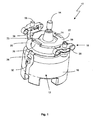
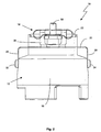
- a rotary angle measuring device 10 shown in FIGS. 1 and 2 has a rotary encoder 12 with an encoder shaft 14.
- the encoder shaft 14 is rotatably connected to a shaft, not shown, of a drive system to be measured, so that the rotation of the encoder shaft 14 corresponds to the shaft of the drive system and the rotation of the shafts can thus be measured via the rotary encoder 12.
- a housing 16 of the rotary encoder 12 can not rotate. Therefore, the housing 16 is usually non-rotatably connected to a non-illustrated stationary part of the drive system to be measured.
- This rotationally fixed connection of the stationary parts of the rotary encoder 12 and the drive can be connected to one another via a stator coupling 18.
- the stator coupling has a torque arm 20 and a mounting plate 22.
- the torque arm 20 causes the actual rotation of the stators, so encoders housing 16 and stationary part of the drive system to be measured.
- the mounting plate 22 is merely for easy installation of the encoder 12 to the drive, as explained below in the description of the assembly process in detail.
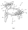
- the torque arm 20 of the illustrated embodiment is shown separately in FIG. It consists of a one-piece punched and bent part 24, which has an annular base plate 26, from the edge of two first substantially diametrically arranged fastening tabs 28 and 30 extending parallel in protrude a first axial direction + R. With these first fastening tabs 28 and 30, the torque arm 20 on the housing 16 via fastening means, in particular screws 32 and 34, can be fixed. In the opposite axial direction -R protrude second fastening tabs 36 and 38, which are also arranged approximately diametrically and which serve the attachment of the torque arm 20 to the stator of the drive system to be measured.
- the torque arm 20 forms a spring parallelogram, which ensures an angle-faithful coupling of the rotary encoder 12 to the drive system to be measured in a special way.
- the torque arm 20 is preferably made of a resilient material high alternating strength, such as spring steel.
- the ends 40 and 42 of the second attachment tabs 36 and 38 are specially designed in accordance with the invention.
- the ends 40 and 42 are bent such that in each case a mounting plane 44 and 46 is formed, which lie approximately parallel to the base plate 26.
- end tabs 48 and 50 of the fastening tab 36 and end tabs 52 and 54 of the fastening tab 38 are bent by approximately 180 ° in such a way that a roughly oval-like shape is formed.
- At least the end tabs 48 and 50 and 52 and 54 are again parallel to the mounting plane 44 and 46 and are superimposed.
- the attachment planes 44 and 46 and the end tabs 48 and 50 and 52 and 54, respectively, are drilled through by fasteners, preferably attachment screws 56 and 58.
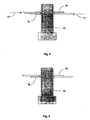
- the end tabs 48 and 50 or 52 and 54 are specially designed.
- the holes in the respective overlying end flaps 48 and 50 or 52 and 54 are not aligned exactly. Only pressure on the arches 60 and 62 or 64 and 66 of the ends 48 and 50 in the direction of the arrows 70 and 72 brings the bores into alignment, so that a fastening screw 56 or 58 can be introduced without problems, as in FIG. 5 shown.
- the fixing screw 56 or 58 is inserted, the pressure is released.
- the end tabs 48 and 50 or 52 and 54 again go a distance apart and the fastening screw 56 or 58 is held jammed in the holes, as shown in Fig. 6.
- stator coupling 18 The function of the stator coupling 18 is clear from the following step-by-step description of the installation of the rotational angular measurement direction 12.
- the stator coupling 14 is attached via the screws 32 and 34 to the rotary encoder 12, wherein the encoder shaft 14 is inserted positively with a hexagonal projection 73 in a recess 74 of the mounting plate 22.
- the mounting plate 22 is supported in the direction -R, the mounting plate 22 is held in position.
- the ends 40 and 42 thus form clamping elements for holding the mounting plate 22.
- the encoder housing 16, the encoder shaft 14 and the stator coupling 18 with its mounting plate 22 form a rotationally fixed unit, as shown in Fig. 1.
- the fastening screws 56 and 58 are also already introduced and held in their shown in Fig. 1 and 2 position in the holes of the mounting tabs 36 and 38.
- the encoder shaft 14 is fixedly secured to a drive shaft of the drive to be measured, e.g. screwed by the encoder housing 16 and thus on the stator coupling 18 with mounting plate 22 ultimately the encoder shaft 14 is rotated. It may be advantageous that areas 76 of the encoder housing 16 also engage in a recess of the mounting plate 22, so that the encoder housing 16 is secured against rotation directly and not only indirectly via the torque arm 20 relative to the mounting plate 22. Then, if necessary, a larger torque for tightening the encoder shaft 14 can be applied without the risk of bending the torque arm 20.
- the encoder shaft 14 After the encoder shaft 14 has been connected to the drive shaft, the already pre-assembled and held by the end tabs mounting screws 56 and 58 attracted. As a result, the mounting plate 22 is moved in the direction of - R and ultimately lifted from the neck 73, whereby the encoder shaft 14 is released.
- the dimensions of the shafts are dimensioned such that when tightening the fasteners 56 and 58, the mounting plate 22 is completely lifted from the neck 73.
- the rotation angle measuring device 10 according to the invention is mounted and ready for operation.
Landscapes
- Physics & Mathematics (AREA)
- General Physics & Mathematics (AREA)
- Transmission And Conversion Of Sensor Element Output (AREA)
- Measurement Of Length, Angles, Or The Like Using Electric Or Magnetic Means (AREA)
- Length Measuring Devices With Unspecified Measuring Means (AREA)
- Body Structure For Vehicles (AREA)
Claims (8)
- Dispositif de mesure d'angle de rotation destiné à la mesure de grandeurs de mesure dépendant de l'angle, comportant un indicateur de rotation (12) avec un arbre d'encodeur (14), qui est monté dans un boîtier (16) d'indicateur de rotation, un accouplement de stator (18) pourvu d'un support (20) de couple de rotation pour la liaison solidaire en rotation du boîtier (16) d'indicateur de rotation avec une partie stationnaire d'un système d'entraînement à mesurer, le support (20) de couple de rotation comportant au moins deux premiers colliers de fixation (28, 30) pour la fixation du support (20) de couple de rotation au boîtier (16) d'indicateur de rotation, et au moins deux deuxièmes colliers de fixation (36, 38) pour la fixation du support (20) de couple de rotation sur la partie stationnaire, caractérisé en ce que les deuxièmes colliers de fixation (36, 38) comportent des moyens de retenue (48, 50 ; 52, 54) pour la retenue de moyens de fixation (56, 58).
- Dispositif de mesure d'angle de rotation selon la revendication 1, caractérisé en ce que les moyens de retenue (48, 50 ; 52, 54) sont respectivement constitués de deux colliers de serrage (48, 50 ; 52, 54) qui enserrent le moyen de fixation(56 ; 58) à l'état détendu.
- Dispositif de mesure d'angle de rotation selon la revendication 2, caractérisé en ce que les colliers de serrage (48, 50 ; 52, 54) sont constitués de deux colliers d'extrémité (48, 50 ; 52, 54) situés l'un au-dessus de l'autre, qui comportent chacun un perçage pour le logement du moyen de fixation (56, 58), et en ce que, à l'état détendu des colliers de serrage (48, 50 ; 52, 54), les perçages sont légèrement décalés parallèlement.
- Dispositif de mesure d'angle de rotation selon la revendication 2 ou 3, caractérisé en ce que les colliers d'extrémité (48, 50 ; 52, 54) sont coudés vers une extrémité de forme grossièrement ovalisée des deuxièmes colliers de fixation (36, 38) respectifs.
- Dispositif de mesure d'angle de rotation selon l'une des revendications précédentes, caractérisé en ce que l'accouplement de stator (18) comporte une plaque de montage (22) pour le montage de l'accouplement de stator (18) sur la partie stationnaire de l'entraînement.
- Dispositif de mesure d'angle de rotation selon la revendication 5, caractérisé en ce que le support (20) de couple de rotation comporte au moins un élément de serrage qui, à l'état non monté de l'indicateur de rotation (12), maintient la plaque de montage (22) sur l'indicateur de rotation (12), et qui pour le montage de l'indicateur de rotation (12) sur la partie stationnaire de l'entraînement, peut se déformer à l'opposé de sa force de serrage.
- Dispositif de mesure d'angle de rotation selon la revendication 6, caractérisé en ce que l'élément de serrage est constitué des deuxièmes colliers de fixation (36, 38) comportant les extrémités de forme ovalisée (40, 42), dont le serrage résulte de la compression de la forme ovale par les moyens de fixation (56, 58).
- Dispositif de mesure d'angle de rotation selon l'une des revendications précédentes, caractérisé en ce que le support de couple de rotation est constitué d'un matériau élastique à ressort, par exemple d'un acier à ressort.
Applications Claiming Priority (2)
| Application Number | Priority Date | Filing Date | Title |
|---|---|---|---|
| DE202004001066U DE202004001066U1 (de) | 2004-01-23 | 2004-01-23 | Drehwinkelmesseinrichtung |
| DE202004001066U | 2004-01-23 |
Publications (3)
| Publication Number | Publication Date |
|---|---|
| EP1557643A1 EP1557643A1 (fr) | 2005-07-27 |
| EP1557643B1 true EP1557643B1 (fr) | 2006-06-07 |
| EP1557643B2 EP1557643B2 (fr) | 2013-04-24 |
Family
ID=32240780
Family Applications (1)
| Application Number | Title | Priority Date | Filing Date |
|---|---|---|---|
| EP05000439.9A Expired - Lifetime EP1557643B2 (fr) | 2004-01-23 | 2005-01-12 | Capteur d'angle de rotation |
Country Status (3)
| Country | Link |
|---|---|
| EP (1) | EP1557643B2 (fr) |
| AT (1) | ATE329232T1 (fr) |
| DE (2) | DE202004001066U1 (fr) |
Families Citing this family (6)
| Publication number | Priority date | Publication date | Assignee | Title |
|---|---|---|---|---|
| DE102006038981B4 (de) * | 2006-08-21 | 2010-09-30 | Lenord, Bauer & Co.Gmbh | Statorkupplung |
| EP2693170B1 (fr) * | 2012-07-31 | 2014-09-24 | SICK STEGMANN GmbH | Couplage de stator |
| DE102012023679C5 (de) * | 2012-11-26 | 2016-11-17 | Fritz Kübler GmbH Zähl- und Sensortechnik | Lagesicherungselement, Drehgebersystem mit einem Lagesicherungselement sowie Verfahren zur Befestigung eines Drehgebersystems |
| CN114234795B (zh) * | 2021-12-17 | 2024-02-13 | 上海易咖智车科技有限公司 | 一种运输车转角机械范围检测装置 |
| CN115164015A (zh) * | 2022-07-11 | 2022-10-11 | 徐州徐工矿业机械有限公司 | 一种工程机械回转平台回转角度监测装置 |
| DE102024129918B3 (de) | 2024-10-15 | 2026-03-12 | Baumer Germany Gmbh & Co. Kg | Drehmomentstütze für einen Drehgeber und ein solcher Drehgeber |
Family Cites Families (5)
| Publication number | Priority date | Publication date | Assignee | Title |
|---|---|---|---|---|
| US5018397A (en) * | 1990-01-26 | 1991-05-28 | The Boeing Company | Transducer input shaft lock mechanism |
| DE19629585C2 (de) * | 1995-09-06 | 1998-12-10 | Heidenhain Gmbh Dr Johannes | Winkelmeßeinrichtung |
| JP2000046244A (ja) † | 1998-07-29 | 2000-02-18 | Nichiei Intekku Kk | 配管バンド装置 |
| DE10102957A1 (de) † | 2001-01-23 | 2002-07-25 | Heidenhain Gmbh Dr Johannes | Winkelmeßsystem |
| DE10216376B4 (de) * | 2002-04-12 | 2005-08-25 | Sick Stegmann Gmbh | Drehwinkel-Messsystem |
-
2004
- 2004-01-23 DE DE202004001066U patent/DE202004001066U1/de not_active Expired - Lifetime
-
2005
- 2005-01-12 DE DE502005000016T patent/DE502005000016D1/de not_active Expired - Lifetime
- 2005-01-12 AT AT05000439T patent/ATE329232T1/de not_active IP Right Cessation
- 2005-01-12 EP EP05000439.9A patent/EP1557643B2/fr not_active Expired - Lifetime
Also Published As
| Publication number | Publication date |
|---|---|
| DE502005000016D1 (de) | 2006-07-20 |
| EP1557643A1 (fr) | 2005-07-27 |
| EP1557643B2 (fr) | 2013-04-24 |
| DE202004001066U1 (de) | 2004-04-29 |
| ATE329232T1 (de) | 2006-06-15 |
Similar Documents
| Publication | Publication Date | Title |
|---|---|---|
| EP1353150B1 (fr) | Capteur d'angle | |
| EP0520164B1 (fr) | Raccord à vis | |
| EP1979634B1 (fr) | Unité de montage destinée à un anneau de fixation d'une boucle de ceinture | |
| DE19629585C2 (de) | Winkelmeßeinrichtung | |
| DE2460961C3 (de) | Vorrichtung zum Aufbringen einer Vorspannkraft auf einen Schraubenbolzen mit Mutter | |
| DE10203278B4 (de) | Kupplung und Winkelmessvorrichtung mit einer derartigen Kupplung | |
| EP3717786A1 (fr) | Dispositif de compensation de tolérance avec sécurité par serrage | |
| EP2331913B1 (fr) | Dispositif de fixation d'une règle par serrage | |
| EP2372202B1 (fr) | Couplage d'un élément de positionnement d'une soupape avec un élément de raccordement d'un mécanisme de commande | |
| AT974U1 (de) | Verbindungsanordnung | |
| EP1557643B1 (fr) | Capteur d'angle de rotation | |
| DE102013113639B3 (de) | Befestigungsvorrichtung zum konzentrischen Befestigen einer Welle an eine Drehgeberwelle und Motorfeedback-System mit dieser Befestigung | |
| DE10063013A1 (de) | Winkelmesseinrichtung | |
| WO2001065634A1 (fr) | Dispositif de fixation d'une antenne de vehicule automobile | |
| EP3765883B1 (fr) | Monture d'ajustage conçue pour réaliser l'ajustage radial d'une unité optique présentant un axe optique | |
| DE102014009257B4 (de) | Exzenterelement und Verfahren zum Einstellen einer Relativposition eines Anbauteils | |
| DE102005059247B4 (de) | Bremsvorrichtung | |
| DE102008021162A1 (de) | Halterung für eine Pedalkraftservoeinrichtung an einer Fahrzeugstruktur | |
| DE10026958A1 (de) | Stator-Kupplung | |
| DE102021114125B3 (de) | Montagewerkzeug zum Montieren eines Nockenwellenverstellers sowie Bausatz mit diesem Montagewerkzeug | |
| EP1643217B1 (fr) | Unité de balayage et arrangement pour mesurer une position | |
| DE102019008731A1 (de) | Schraubanordnung | |
| DE10031610A1 (de) | Kettenspanner | |
| DE202006010183U1 (de) | Winkelmesseinrichtung und Messanordnung mit einer derartigen Winkelmesseinrichtung | |
| EP2818617B2 (fr) | Élément de réception de paumelle pour paumelles de porte |
Legal Events
| Date | Code | Title | Description |
|---|---|---|---|
| PUAI | Public reference made under article 153(3) epc to a published international application that has entered the european phase |
Free format text: ORIGINAL CODE: 0009012 |
|
| AK | Designated contracting states |
Kind code of ref document: A1 Designated state(s): AT BE BG CH CY CZ DE DK EE ES FI FR GB GR HU IE IS IT LI LT LU MC NL PL PT RO SE SI SK TR |
|
| AX | Request for extension of the european patent |
Extension state: AL BA HR LV MK YU |
|
| 17P | Request for examination filed |
Effective date: 20051012 |
|
| GRAP | Despatch of communication of intention to grant a patent |
Free format text: ORIGINAL CODE: EPIDOSNIGR1 |
|
| AKX | Designation fees paid |
Designated state(s): AT BE BG CH CY CZ DE DK EE ES FI FR GB GR HU IE IS IT LI LT LU MC NL PL PT RO SE SI SK TR |
|
| GRAS | Grant fee paid |
Free format text: ORIGINAL CODE: EPIDOSNIGR3 |
|
| GRAA | (expected) grant |
Free format text: ORIGINAL CODE: 0009210 |
|
| AK | Designated contracting states |
Kind code of ref document: B1 Designated state(s): AT BE BG CH CY CZ DE DK EE ES FI FR GB GR HU IE IS IT LI LT LU MC NL PL PT RO SE SI SK TR |
|
| PG25 | Lapsed in a contracting state [announced via postgrant information from national office to epo] |
Ref country code: IT Free format text: LAPSE BECAUSE OF FAILURE TO SUBMIT A TRANSLATION OF THE DESCRIPTION OR TO PAY THE FEE WITHIN THE PRESCRIBED TIME-LIMIT;WARNING: LAPSES OF ITALIAN PATENTS WITH EFFECTIVE DATE BEFORE 2007 MAY HAVE OCCURRED AT ANY TIME BEFORE 2007. THE CORRECT EFFECTIVE DATE MAY BE DIFFERENT FROM THE ONE RECORDED. Effective date: 20060607 Ref country code: CZ Free format text: LAPSE BECAUSE OF FAILURE TO SUBMIT A TRANSLATION OF THE DESCRIPTION OR TO PAY THE FEE WITHIN THE PRESCRIBED TIME-LIMIT Effective date: 20060607 Ref country code: IE Free format text: LAPSE BECAUSE OF FAILURE TO SUBMIT A TRANSLATION OF THE DESCRIPTION OR TO PAY THE FEE WITHIN THE PRESCRIBED TIME-LIMIT Effective date: 20060607 Ref country code: LT Free format text: LAPSE BECAUSE OF FAILURE TO SUBMIT A TRANSLATION OF THE DESCRIPTION OR TO PAY THE FEE WITHIN THE PRESCRIBED TIME-LIMIT Effective date: 20060607 Ref country code: RO Free format text: LAPSE BECAUSE OF FAILURE TO SUBMIT A TRANSLATION OF THE DESCRIPTION OR TO PAY THE FEE WITHIN THE PRESCRIBED TIME-LIMIT Effective date: 20060607 Ref country code: PL Free format text: LAPSE BECAUSE OF FAILURE TO SUBMIT A TRANSLATION OF THE DESCRIPTION OR TO PAY THE FEE WITHIN THE PRESCRIBED TIME-LIMIT Effective date: 20060607 Ref country code: SK Free format text: LAPSE BECAUSE OF FAILURE TO SUBMIT A TRANSLATION OF THE DESCRIPTION OR TO PAY THE FEE WITHIN THE PRESCRIBED TIME-LIMIT Effective date: 20060607 Ref country code: FI Free format text: LAPSE BECAUSE OF FAILURE TO SUBMIT A TRANSLATION OF THE DESCRIPTION OR TO PAY THE FEE WITHIN THE PRESCRIBED TIME-LIMIT Effective date: 20060607 Ref country code: NL Free format text: LAPSE BECAUSE OF FAILURE TO SUBMIT A TRANSLATION OF THE DESCRIPTION OR TO PAY THE FEE WITHIN THE PRESCRIBED TIME-LIMIT Effective date: 20060607 Ref country code: SI Free format text: LAPSE BECAUSE OF FAILURE TO SUBMIT A TRANSLATION OF THE DESCRIPTION OR TO PAY THE FEE WITHIN THE PRESCRIBED TIME-LIMIT Effective date: 20060607 |
|
| REG | Reference to a national code |
Ref country code: GB Ref legal event code: FG4D Free format text: NOT ENGLISH |
|
| REG | Reference to a national code |
Ref country code: CH Ref legal event code: EP |
|
| GBT | Gb: translation of ep patent filed (gb section 77(6)(a)/1977) |
Effective date: 20060607 |
|
| REG | Reference to a national code |
Ref country code: IE Ref legal event code: FG4D Free format text: LANGUAGE OF EP DOCUMENT: GERMAN |
|
| REF | Corresponds to: |
Ref document number: 502005000016 Country of ref document: DE Date of ref document: 20060720 Kind code of ref document: P |
|
| PG25 | Lapsed in a contracting state [announced via postgrant information from national office to epo] |
Ref country code: DK Free format text: LAPSE BECAUSE OF FAILURE TO SUBMIT A TRANSLATION OF THE DESCRIPTION OR TO PAY THE FEE WITHIN THE PRESCRIBED TIME-LIMIT Effective date: 20060907 Ref country code: SE Free format text: LAPSE BECAUSE OF FAILURE TO SUBMIT A TRANSLATION OF THE DESCRIPTION OR TO PAY THE FEE WITHIN THE PRESCRIBED TIME-LIMIT Effective date: 20060907 |
|
| PG25 | Lapsed in a contracting state [announced via postgrant information from national office to epo] |
Ref country code: ES Free format text: LAPSE BECAUSE OF FAILURE TO SUBMIT A TRANSLATION OF THE DESCRIPTION OR TO PAY THE FEE WITHIN THE PRESCRIBED TIME-LIMIT Effective date: 20060918 |
|
| PG25 | Lapsed in a contracting state [announced via postgrant information from national office to epo] |
Ref country code: PT Free format text: LAPSE BECAUSE OF FAILURE TO SUBMIT A TRANSLATION OF THE DESCRIPTION OR TO PAY THE FEE WITHIN THE PRESCRIBED TIME-LIMIT Effective date: 20061107 |
|
| NLV1 | Nl: lapsed or annulled due to failure to fulfill the requirements of art. 29p and 29m of the patents act | ||
| REG | Reference to a national code |
Ref country code: IE Ref legal event code: FD4D |
|
| PG25 | Lapsed in a contracting state [announced via postgrant information from national office to epo] |
Ref country code: MC Free format text: LAPSE BECAUSE OF NON-PAYMENT OF DUE FEES Effective date: 20070131 |
|
| PLBI | Opposition filed |
Free format text: ORIGINAL CODE: 0009260 |
|
| 26 | Opposition filed |
Opponent name: DR. JOHANNES HEIDENHAIN GMBH Effective date: 20070220 |
|
| PLAX | Notice of opposition and request to file observation + time limit sent |
Free format text: ORIGINAL CODE: EPIDOSNOBS2 |
|
| EN | Fr: translation not filed | ||
| PLBB | Reply of patent proprietor to notice(s) of opposition received |
Free format text: ORIGINAL CODE: EPIDOSNOBS3 |
|
| BERE | Be: lapsed |
Owner name: SICK STEGMANN G.M.B.H. Effective date: 20070131 |
|
| PG25 | Lapsed in a contracting state [announced via postgrant information from national office to epo] |
Ref country code: BE Free format text: LAPSE BECAUSE OF NON-PAYMENT OF DUE FEES Effective date: 20070131 |
|
| PG25 | Lapsed in a contracting state [announced via postgrant information from national office to epo] |
Ref country code: GR Free format text: LAPSE BECAUSE OF FAILURE TO SUBMIT A TRANSLATION OF THE DESCRIPTION OR TO PAY THE FEE WITHIN THE PRESCRIBED TIME-LIMIT Effective date: 20060908 Ref country code: FR Free format text: LAPSE BECAUSE OF FAILURE TO SUBMIT A TRANSLATION OF THE DESCRIPTION OR TO PAY THE FEE WITHIN THE PRESCRIBED TIME-LIMIT Effective date: 20070309 |
|
| PG25 | Lapsed in a contracting state [announced via postgrant information from national office to epo] |
Ref country code: BG Free format text: LAPSE BECAUSE OF FAILURE TO SUBMIT A TRANSLATION OF THE DESCRIPTION OR TO PAY THE FEE WITHIN THE PRESCRIBED TIME-LIMIT Effective date: 20060907 Ref country code: AT Free format text: LAPSE BECAUSE OF NON-PAYMENT OF DUE FEES Effective date: 20070112 |
|
| PG25 | Lapsed in a contracting state [announced via postgrant information from national office to epo] |
Ref country code: EE Free format text: LAPSE BECAUSE OF FAILURE TO SUBMIT A TRANSLATION OF THE DESCRIPTION OR TO PAY THE FEE WITHIN THE PRESCRIBED TIME-LIMIT Effective date: 20060607 |
|
| PG25 | Lapsed in a contracting state [announced via postgrant information from national office to epo] |
Ref country code: FR Free format text: LAPSE BECAUSE OF FAILURE TO SUBMIT A TRANSLATION OF THE DESCRIPTION OR TO PAY THE FEE WITHIN THE PRESCRIBED TIME-LIMIT Effective date: 20060607 |
|
| PG25 | Lapsed in a contracting state [announced via postgrant information from national office to epo] |
Ref country code: IS Free format text: LAPSE BECAUSE OF NON-PAYMENT OF DUE FEES Effective date: 20070131 |
|
| PGRI | Patent reinstated in contracting state [announced from national office to epo] |
Ref country code: IT Effective date: 20090301 |
|
| PG25 | Lapsed in a contracting state [announced via postgrant information from national office to epo] |
Ref country code: CY Free format text: LAPSE BECAUSE OF FAILURE TO SUBMIT A TRANSLATION OF THE DESCRIPTION OR TO PAY THE FEE WITHIN THE PRESCRIBED TIME-LIMIT Effective date: 20060607 Ref country code: LU Free format text: LAPSE BECAUSE OF NON-PAYMENT OF DUE FEES Effective date: 20070112 |
|
| REG | Reference to a national code |
Ref country code: CH Ref legal event code: PL |
|
| PG25 | Lapsed in a contracting state [announced via postgrant information from national office to epo] |
Ref country code: HU Free format text: LAPSE BECAUSE OF FAILURE TO SUBMIT A TRANSLATION OF THE DESCRIPTION OR TO PAY THE FEE WITHIN THE PRESCRIBED TIME-LIMIT Effective date: 20061208 Ref country code: TR Free format text: LAPSE BECAUSE OF FAILURE TO SUBMIT A TRANSLATION OF THE DESCRIPTION OR TO PAY THE FEE WITHIN THE PRESCRIBED TIME-LIMIT Effective date: 20060607 |
|
| PG25 | Lapsed in a contracting state [announced via postgrant information from national office to epo] |
Ref country code: LI Free format text: LAPSE BECAUSE OF NON-PAYMENT OF DUE FEES Effective date: 20090131 Ref country code: CH Free format text: LAPSE BECAUSE OF NON-PAYMENT OF DUE FEES Effective date: 20090131 |
|
| PUAH | Patent maintained in amended form |
Free format text: ORIGINAL CODE: 0009272 |
|
| STAA | Information on the status of an ep patent application or granted ep patent |
Free format text: STATUS: PATENT MAINTAINED AS AMENDED |
|
| 27A | Patent maintained in amended form |
Effective date: 20130424 |
|
| AK | Designated contracting states |
Kind code of ref document: B2 Designated state(s): AT BE BG CH CY CZ DE DK EE ES FI FR GB GR HU IE IS IT LI LT LU MC NL PL PT RO SE SI SK TR |
|
| PGFP | Annual fee paid to national office [announced via postgrant information from national office to epo] |
Ref country code: GB Payment date: 20130122 Year of fee payment: 9 |
|
| REG | Reference to a national code |
Ref country code: DE Ref legal event code: R102 Ref document number: 502005000016 Country of ref document: DE Effective date: 20130424 |
|
| GBPC | Gb: european patent ceased through non-payment of renewal fee |
Effective date: 20140112 |
|
| PG25 | Lapsed in a contracting state [announced via postgrant information from national office to epo] |
Ref country code: GB Free format text: LAPSE BECAUSE OF NON-PAYMENT OF DUE FEES Effective date: 20140112 |
|
| REG | Reference to a national code |
Ref country code: DE Ref legal event code: R082 Ref document number: 502005000016 Country of ref document: DE Ref country code: DE Ref legal event code: R081 Ref document number: 502005000016 Country of ref document: DE Owner name: SICK AG, DE Free format text: FORMER OWNER: SICK STEGMANN GMBH, 78166 DONAUESCHINGEN, DE |
|
| PGFP | Annual fee paid to national office [announced via postgrant information from national office to epo] |
Ref country code: IT Payment date: 20230131 Year of fee payment: 19 |
|
| PGFP | Annual fee paid to national office [announced via postgrant information from national office to epo] |
Ref country code: DE Payment date: 20240119 Year of fee payment: 20 |
|
| REG | Reference to a national code |
Ref country code: DE Ref legal event code: R071 Ref document number: 502005000016 Country of ref document: DE |
|
| PG25 | Lapsed in a contracting state [announced via postgrant information from national office to epo] |
Ref country code: IT Free format text: LAPSE BECAUSE OF NON-PAYMENT OF DUE FEES Effective date: 20240112 |