EP1557641A1 - Verfahren und Messvorrichtung zum Ermitteln der Ausrichtung eines zylindrischen Körpers - Google Patents
Verfahren und Messvorrichtung zum Ermitteln der Ausrichtung eines zylindrischen Körpers Download PDFInfo
- Publication number
- EP1557641A1 EP1557641A1 EP04001176A EP04001176A EP1557641A1 EP 1557641 A1 EP1557641 A1 EP 1557641A1 EP 04001176 A EP04001176 A EP 04001176A EP 04001176 A EP04001176 A EP 04001176A EP 1557641 A1 EP1557641 A1 EP 1557641A1
- Authority
- EP
- European Patent Office
- Prior art keywords
- measurement
- peripheral surface
- probe
- angle
- respect
- Prior art date
- Legal status (The legal status is an assumption and is not a legal conclusion. Google has not performed a legal analysis and makes no representation as to the accuracy of the status listed.)
- Granted
Links
- 238000005259 measurement Methods 0.000 title claims abstract description 83
- 238000000034 method Methods 0.000 title claims abstract description 29
- 239000000523 sample Substances 0.000 claims abstract description 71
- 230000002093 peripheral effect Effects 0.000 claims abstract description 44
- 238000011156 evaluation Methods 0.000 claims description 7
- 230000001404 mediated effect Effects 0.000 claims description 2
- 230000003287 optical effect Effects 0.000 claims description 2
- 238000003825 pressing Methods 0.000 claims description 2
- 230000000717 retained effect Effects 0.000 claims 1
- 230000008569 process Effects 0.000 abstract description 3
- 238000001514 detection method Methods 0.000 description 3
- 230000008859 change Effects 0.000 description 2
- 239000007787 solid Substances 0.000 description 2
- 230000001419 dependent effect Effects 0.000 description 1
- 230000004048 modification Effects 0.000 description 1
- 238000012986 modification Methods 0.000 description 1
- 238000005096 rolling process Methods 0.000 description 1
- 230000009466 transformation Effects 0.000 description 1
Images


Classifications
-
- G—PHYSICS
- G01—MEASURING; TESTING
- G01B—MEASURING LENGTH, THICKNESS OR SIMILAR LINEAR DIMENSIONS; MEASURING ANGLES; MEASURING AREAS; MEASURING IRREGULARITIES OF SURFACES OR CONTOURS
- G01B21/00—Measuring arrangements or details thereof, where the measuring technique is not covered by the other groups of this subclass, unspecified or not relevant
- G01B21/22—Measuring arrangements or details thereof, where the measuring technique is not covered by the other groups of this subclass, unspecified or not relevant for measuring angles or tapers; for testing the alignment of axes
- G01B21/24—Measuring arrangements or details thereof, where the measuring technique is not covered by the other groups of this subclass, unspecified or not relevant for measuring angles or tapers; for testing the alignment of axes for testing alignment of axes
Definitions
- the present invention relates to a method and a device for determining the Alignment of a cylindrical body with respect to a reference direction by means of a Lümesssonde that is calibrated to the reference direction and to capture a first Angle of rotation about a first defined solid axis and a second angle of rotation about one second defined solid space axis is formed.
- Such a measuring device or such a measuring method are for example from the DE 199 49 834 A1 discloses, wherein by means of the position measuring probe in a first measuring position the peripheral surface of the cylindrical body is carried out a first position measurement and in at least one second measuring position on the peripheral surface of the body, extending through its rotational angle in the circumferential direction with respect to the body axis of the first Measuring position is different, a second position measurement is performed, and from the measured data calculated the orientation of the body with respect to the reference direction becomes.
- the disadvantage here is that while determining the orientation of the body mandatory the Measurement of the rotation angle with appropriate accuracy is required.
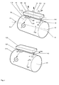
- a measuring device 100 is shown, which on the peripheral surface of a first roller 110, which may be, for example, a pressure roller, created or is scheduled.
- the measuring device 100 comprises a position measuring probe 130, which at its front end a first attachment area, which is formed by a magnetic base 120, and at its rear end a second attachment region formed by a stylus tip 140.
- the Lümesssonde 130 is formed so that they each by means of a mechanical or optical gyroscope the angle of rotation of the probe 130 about a space fixed elevation axis 12, the that is approximately in the transverse direction of the probe 130 and in the example shown substantially is perpendicular to the roll longitudinal axis 10 and tangent to the roll peripheral surface, and about a perpendicular azimuthal axis 14, which in the example shown in the is substantially perpendicular to the roll longitudinal axis 10 and to the roll peripheral surface, can capture.
- a rotation about the axis 14 then changes the azimuth angle ("Yaw") and a rotation about the axis 12 the elevation angle ("pitch").
- the detection of the angle of rotation about an axis 16, which is approximately in the longitudinal direction of the probe 130th runs and is perpendicular to the axes 12 and 14, can be optional, if necessary (The rotation about the axis 16 indicates the so-called "roll angle").
- the measuring device 100 is shown in the position at the beginning of a first measurement.
- the magnetic base 120 is in the first measuring position E with respect to the roller circumferential surface determined while the probe tip 140 at a point A2 on the roller peripheral surface is scheduled.
- the probe 130 is mounted with respect to the magnetic base 120 so that it is around a Axis 30, which is substantially parallel to axis 14 in the measuring position shown, as well as about a perpendicular axis 32, which in the measuring position shown in is substantially parallel to the axis 12, with respect to the magnetic base is rotatable.
- the magnetic base 120 and the probe tip 140 are dimensioned so that the probe 130 is not around the axis 12 is tilted with respect to the roller 110 or the roller longitudinal axis 10, i. the Probe 130 should be as exactly as possible parallel to the roll surface. Furthermore, lies the Longitudinal axis 16 of the probe 130 is preferably approximately parallel to the roll axis 10, i. the connecting line between the magnetic base 120 and the probe tip 140 is approximately parallel to the roll axis 10.
- the first measurement is carried out by the probe tip 140 starting from the Support point A2 in contact with the roller peripheral surface manually to the support point A2 ' is moved, wherein the probe 130 about the axis 30 with respect to the magnetic base 120th is pivoted.
- the line of movement of the probe tip 140 is on the Roller circumferential surface in the first measurement by the reference numeral 34 denotes.
- the points A2 and A2 ' are selected such that when the probe tip 140 is located in the middle between the two points, the probe 130 exactly parallel to the Roller shaft 10 is.
- the Recording process can be started or stopped by means of a detector device be, for example, the pressing force of the probe tip 140 on the roller peripheral surface or the existence of an electrical contact mediated by the roller peripheral surface detected between the magnetic base 120 and the probe tip 140.
- the magnetic base 120 is released and the measuring device 100 is in a Position brought in which the magnetic base 120 in the position Z at the Roll peripheral surface is set, while the probe tip 140 in the start position B2 is brought.
- the second measurement in which the Probe tip 140 analogous to the first measurement from position B2 in contact with the Roll peripheral surface is manually brought to the position B2 ', in which the second Measurement is stopped.
- a pivoting of the probe takes place 130 around the bearing axis 30.
- the magnetic base 120 is preferably formed so that the Axis 30 can be pivoted about the axis 16 so that the axis 30 at the second Measurement at least approximately parallel to the orientation of the axis 30 at the first Measurement, e.g. by the bearing is designed as a ball bearing.
- a check of the Orientation of the pivot axis 30 could for example by means of a pendulum weight or a level provided on the probe 130 (not shown).
- the aim of the measurements is the alignment of the roll axis 10 with respect to a Reference direction 10 ', i. the horizontal deviation ⁇ h and the vertical deviation ⁇ v the roll axis 10 with respect to the reference direction 10 'to determine.
- the Probe 130 is calibrated to reference direction 10 ', i. it measures the pitch and yaw angles as a deviation from the reference direction.
- FIG. 5 shows, by way of example, the result of the above-described measuring process, in which for both the first measurement and the second measurement, the measured pitch angle as Function of the measured Yaw angle is plotted.
- the curves of the first and the second measurement are designated MA or MB.
- For both measurements results each a circular arc whose radius is identical and whose center, however according to the different roll angle of the positions E and Z is different.
- a measurement of the roll angle (Rotation of the probe about the axis 16) is not required. This is especially true when the roll angle is kept constant during the first and second measurements.
- Fig. 1 is further indicated that the probe 130 after determining the orientation of the first roller 110 can be applied in an analogous manner to a second roller 210 to their Alignment with respect to the reference direction 10 'or another reference direction determine (in the latter case, the calibration of the probe 130 before the measurement accordingly be changed).
- the second roller 210 is parallel to the first roller 110 is to be aligned, it is appropriate that the determined orientation of the first roller 110 is used as the reference direction for the alignment measurement of the second roller 210.
- the measuring methods described can also be used to determine from the radii of the Circular arcs MA and MB to determine the roller radius. If further instead of the previously described two measurements on a roller a third analog measurement in a third Roll angle is performed, which optionally a conical or crowning of the Roller can be determined.
- a survey of several rolls can be carried out in the vocational step method.
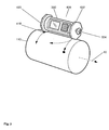
- the calibration of the probe 130 on the reference direction 10 'can take place, for example, by that the probe 130 prior to the first measurement to a corresponding fixed Reference surface combination 410, 430, as shown schematically in Fig. 2, created becomes.
- FIG. 2 shows a second embodiment of a measuring device 300 in which the Probe 330 is provided instead of a Tastspitze with a circular disk 322 as Ansetz Berlin.
- 324 is a handle for manual pivoting of the probe 330 during the first and the second measurement.
- the circular disk 322 can in this case with respect to the probe 330 fixed and acts in this case as a circular curved cutting edge, which forms a point contact with the roller peripheral surface during the measurement.
- manual Pivoting the probe 330 during the measurement slides the disc 322 on the Roll circumferential surface.
- the front support point 318 of the probe 330 is like the previous embodiment during each individual measurement fixed and serves as Fulcrum.
- the circular disc 322 may also be rotatable be mounted with respect to the probe 330 and act in this case as a wheel which at Pivoting the probe 330 around the front support point 318 during each measurement rolls the roller peripheral surface.
- the front end of the probe 330 may also be provided with a circular disk 320 be provided, the stationary on their circumference during the respective measurement Ansetztician 318 forms.
- the measuring device 300 it is possible to unroll the probe 330 on the roller peripheral surface about the roller axis 10 bring the probe 330 from the first measuring position to the second measuring position.
- a roll angle detection must be done to get the measurement results evaluate. If a detection of the roll angle should be avoided, the probe is likely 330 does not roll on the roller peripheral surface, but would have to slipping off the Circular disks 320, 322 on the roller peripheral surface so from the first to the second In this case, no rolling movement of the probe 330, i. none Rotation about the longitudinal axis of the probe 330, takes place.
- a modification of the embodiment of Fig. 1 is shown, wherein the Probe tip 140 is replaced by a straight cutting edge 540, which at one point on the Roller peripheral surface rests.
- the cutting edge 540 is manually in contact with the roller peripheral surface pushed over the roller peripheral surface, whereby the probe 130 is pivoted about the magnetic shoe 120 and the axis 30. If the axis 30 is not tilts sideways, only the yaw angle changes with each measurement, but not the pitch angle.
- a straight line results, wherein this offset to the straight line measured at another roll angle, since the pitch angle at every measurement depends on the roll angle. For the lines to intersect, is to determine the misalignment, the evaluation of the roll angle in this case mandatory.
- the cutting edge 540 may also be curved, for example, arcuately curved, be formed.
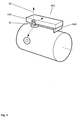
- FIG. 3 A modified embodiment of the principle of Fig. 2 is shown in Fig. 3, where the two circular disks 320, 322 through a corresponding disc 420, 422 with polygonal Outer circumference are replaced.
- the respective straight section of the polygon with which the rear disc 422 is placed on the roller peripheral surface is doing manually at the respective measurement in contact with the roller peripheral surface over the roller peripheral surface pushed, wherein the probe 330 is pivoted about the front bearing point 418.
- this is equivalent functional of the embodiment of Fig. 4.
- the different sections of the polygon are used to create a Roll angle influence to keep low.
- the front attachment point of the Probe on the roller peripheral surface should also be designed so that during the Pivoting the rear attachment point a certain tilting of the probe, i.e. a change in the roll angle of the probe is allowed. In this case, however, the Roll angle or its change to be recorded to a reliable evaluation of To allow measurement results of the pitch and yaw angle.
- the swing angle range of the rear Ansetzddlings to the front attachment point chosen so that a sufficiently large number of Measured value pairs (pitch angle, yaw angle) is obtained to make a reliable Curve fitting and thus a reliable determination of the intersection of the curves enable.
- the pivot angle is at least 10 °.
- the measuring device To evaluate the measured values or to determine the orientation of the to be measured Roller, the measuring device is provided with a corresponding evaluation unit, which in the However, figures are not shown separately.
Landscapes
- Physics & Mathematics (AREA)
- General Physics & Mathematics (AREA)
- A Measuring Device Byusing Mechanical Method (AREA)
- Length Measuring Devices With Unspecified Measuring Means (AREA)
Abstract
Description
Claims (23)
- Verfahren zum Ermitteln der Ausrichtung eines zylindrischen Körpers (110, 210) bezüglich einer Referenzrichtung (10') mittels einer Messvorrichtung (100, 300, 400, 500), die einen ersten (120, 320, 420) und einen zweiten Ansetzbereich (140, 322, 422, 540) und eine Lagemesssonde (130, 330) aufweist, die auf die Referenzrichtung geeicht ist und zur Erfassung eines ersten Drehwinkels der Sonde um eine erste raumfeste Achse (12) und eines zweiten Drehwinkels der Sonde um eine zweite raumfeste Achse (14) ausgebildet ist,
wobei eine erste Messung durchgeführt wird, bei welcher die Sonde mit dem ersten und dem zweiten Ansetzbereich auf der Umfangsfläche des Körpers angesetzt wird, wobei der erste Ansetzbereich eine erste Messposition (E, E') einnimmt, in welcher er bezüglich der Körperumfangsfläche festgehalten wird, während der zweite Ansetzbereich in Kontakt mit der Körperumfangsfläche bezüglich des ersten Ansetzbereichs verschwenkt wird und dabei der Verlauf des ersten und des zweiten Drehwinkels erfasst wird,
und anschließend eine zweite Messung durchgeführt wird, bei welcher die Sonde mit dem ersten und dem zweiten Ansetzbereich auf der Umfangsfläche des Körpers angesetzt wird, wobei der erste Ansetzbereich eine zweite Messposition (Z, Z') einnimmt, die bezüglich der ersten Messposition des ersten Ansetzbereichs in Umfangsrichtung versetzt ist und in welcher er bezüglich der Körperumfangsfläche festgehalten wird, während der zweite Ansetzbereich in Kontakt mit der Körperumfangsfläche bezüglich des ersten Ansetzbereichs verschwenkt wird und dabei der Verlauf des ersten und des zweiten Drehwinkels erfasst wird,
und wobei aus dem Vergleich des bei der ersten Messung gewonnen Verlaufs (MA) des ersten und des zweiten Drehwinkels und des bei der zweiten Messung gewonnen Verlaufs (MB) ersten und des zweiten Drehwinkels die Ausrichtung des Körpers bezüglich der Referenzrichtung ermittelt wird. - Verfahren gemäß Anspruch 1, dadurch gekennzeichnet, dass die erste Achse (12) zu der zweiten Achse (14) senkrecht ist.
- Verfahren gemäß Anspruch 2; dadurch gekennzeichnet, dass die erste (12) und die zweite Achse (14) so liegen, dass es sich, wenn die Sonde (130, 330) horizontal ausgerichtet ist, bei dem ersten Drehwinkel um den Elevations-Winkel (Pitch-Winkel) und bei dem zweiten Drehwinkel um den Azimut-Winkel (Yaw-Winkel) handelt.
- Verfahren gemäß einem der vorhergehenden Ansprüche, dadurch gekennzeichnet, dass bei der Auswertung für die erste und die zweite Messung jeweils der erste Drehwinkel als Funktion des zweiten Drehwinkels oder umgekehrt dargestellt wird und die Abweichung der Ausrichtung des Körpers von der Referenzrichtung aus dem Schnittpunkt (X) der Kurve (MA) der ersten Messung mit der entsprechenden Kurve (MB) der zweiten Messung ermittelt wird.
- Verfahren gemäß Anspruch 4, dadurch gekennzeichnet, dass aus den Messwerten der ersten bzw. der zweiten Messung durch Kurvenanpassung jeweils eine Ausgleichsfunktion ermittelt wird, wobei die Abweichung der Ausrichtung des Körpers von der Referenzrichtung aus dem Schnittpunkt dieser Ausgleichsfunktionen ermittelt wird.
- Verfahren gemäß einem der vorhergehenden Ansprüche, dadurch gekennzeichnet, dass die erste und die zweite Messung über einen Schwenkwinkelbereich des zweiten Ansetzbereichs (140, 322, 422, 540) bezüglich des ersten Ansetzbereichs (120, 320, 420) von mindestens 10 Grad ausgeführt wird.
- Verfahren gemäß einem der vorhergehenden Ansprüche, dadurch gekennzeichnet, dass bei der zweiten Messung die Messsonde (130, 330) sowohl in der Anfangsstellung als auch in der Endstellung im wesentlichen parallel zu den entsprechenden Positionen bei der ersten Messung ist.
- Verfahren gemäß einem der vorhergehenden Ansprüche, dadurch gekennzeichnet, dass die Sonde (130, 330) während der ersten bzw. der zweiten Messung im wesentlichen so ausgerichtet ist, dass die Verbindungslinie zwischen dem ersten und dem zweiten Ansetzbereich im wesentlichen parallel zu der Längsachse (10, 20) des Körpers (110, 210) ausgerichtet ist.
- Verfahren gemäß einem der vorhergehenden Ansprüche, dadurch gekennzeichnet, dass der zweite Ansetzbereich als Spitze (140) ausgebildet ist, die bei der ersten und der zweiten Messung in Kontakt mit der Körperumfangsfläche manuell über die Körperumfangsfläche geschoben wird.
- Verfahren gemäß einem der Ansprüche 1 bis 9, dadurch gekennzeichnet, dass der zweite Ansetzbereich als Rad (322) ausgebildet ist, das bezüglich der Sonde (330) drehbar gelagert ist und tangential bezüglich der Schwenkbewegung des zweiten Ansetzbereichs relativ zum ersten Ansetzbereich (320) steht, wobei das Rad bei der ersten und der zweiten Messung auf der Körperumfangsfläche manuell abgerollt wird.
- Verfahren gemäß einem der Ansprüche 1 bis 9, dadurch gekennzeichnet, dass der zweite Ansetzbereich als Schneide (322, 540) ausgebildet ist, die tangential bezüglich der Schwenkbewegung des zweiten Ansetzbereichs relativ zum ersten Ansetzbereich (120, 320) steht, wobei die Schneide bei der ersten und der zweiten Messung in Kontakt mit der Körperumfangsfläche manuell über die Körperumfangsfläche geschoben wird.
- Verfahren gemäß Anspruch 11, dadurch gekennzeichnet, dass die Schneide (540) eben oder als Polygonzug ausgebildet ist.
- Verfahren gemäß Anspruch 11, dadurch gekennzeichnet, dass die Schneide (540, 322) gekrümmt, insbesondere kreisförmig bzw. kreisbogenförmig gekrümmt, ausgebildet ist.
- Verfahren gemäß einem der vorhergehenden Ansprüche, dadurch gekennzeichnet, dass eine Detektoreinrichtung vorgesehen ist, um zu erfassen, wenn der zweite Ansetzbereich (140, 322, 422, 540) in Kontakt mit der Körperumfangsfläche steht, in welchem Fall Messwerte für den Verlauf des ersten und des zweiten Drehwinkels aufgenommen werden.
- Verfahren gemäß Anspruch 14, dadurch gekennzeichnet, dass die Detektoreinrichtung die Andrückkraft des zweiten Ansetzbereichs (140, 322, 422, 540) an der Körperumfangsfläche erfasst.
- Verfahren gemäß Anspruch 14, dadurch gekennzeichnet, dass die Detektoreinrichtung erfasst, ob ein von der Körperumfangsfläche vermittelter elektrischer Kontakt zwischen dem ersten (120, 320, 420) und dem zweiten Ansetzbereich (140, 322, 422, 540) besteht.
- Verfahren gemäß einem der vorhergehenden Ansprüche, dadurch gekennzeichnet, dass die Achse der Schwenkbewegung bei der ersten Messung und die Achse der Schwenkbewegung bei der zweiten Messung im wesentlichen zueinander parallel stehen.
- Messvorrichtung zum Ermitteln der Ausrichtung eines zylindrischen Körpers (110, 210) bezüglich einer Referenzrichtung (10'), mit einer Lagemesssonde (130, 330), die auf die Referenzrichtung geeicht ist und zur Erfassung eines ersten Drehwinkels der Sonde um eine erste raumfeste Achse (12) und eines zweiten Drehwinkels der Sonde um eine zweite raumfeste Achse (14) ausgebildet ist, sowie einem ersten Ansetzbereich (120, 320, 420) und einem zweiten Ansetzbereich (140, 322, 422, 540) zum Ansetzen der Sonde auf der Umfangsfläche des Körpers, sowie einer Auswerteeinheit,
wobei der erste und der zweite Ansetzbereich so ausgebildet sind, dass der erste Ansetzbereich für eine erste Messung nach den Ansetzen eine erste Messposition (E, E') einnimmt, welche er beibehält, während der zweite Ansetzbereich in Kontakt mit der Körperumfangsfläche bezüglich des ersten Ansetzbereichs verschwenkbar ist, und wobei der erste Ansetzbereich für eine zweite Messung in eine zweite Messposition (Z, Z') bringbar ist, die bezüglich der ersten Messposition des ersten Ansetzbereichs in Umfangsrichtung versetzt ist und welche er beibehält, während der zweite Ansetzbereich in Kontakt mit der Körperumfangsfläche bezüglich des ersten Ansetzbereichs verschwenkbar ist, und
wobei die Auswerteeinheit so ausgebildet ist, dass während der ersten und der zweiten Messung der Verlauf des ersten und des zweiten Drehwinkels erfasst wird und aus dem Vergleich des bei der ersten Messung gewonnen Verlaufs (MA) des ersten und des zweiten Drehwinkels und des bei der zweiten Messung gewonnen Verlaufs (MB) ersten und des zweiten Drehwinkels die Ausrichtung des Körpers bezüglich der Referenzrichtung ermittelt wird. - Vorrichtung gemäß Anspruch 18, dadurch gekennzeichnet, dass der erste Ansetzbereich einen an der Körperumfangsfläche lösbar anbringbaren Fuß (120) aufweist, der bezüglich der Sonde (130, 330) um zwei senkrecht zueinander stehende Achsen (30, 32) schwenkbar ist.
- Vorrichtung gemäß Anspruch 19, dadurch gekennzeichnet, dass die erste Schwenkachse (30) des Fußes (120) senkrecht zu der Körperumfangsfläche steht und die zweite Schwenkachse (32) des Fußes senkrecht zu der Verbindungslinie zwischen dem ersten und dem zweiten Ansetzbereich (140, 540) steht.
- Vorrichtung gemäß Anspruch 20, dadurch gekennzeichnet, dass die Ausrichtung der ersten Schwenkachse (30) des Fußes (120) bezüglich des Fußes fest ist dergestalt variabel ist, dass die erste Schwenkachse unabhängig von der Position des Fußes auf der Körperumfangsfläche im wesentlichen raumfest und zu der zweiten raumfesten Achse parallel ist..
- Vorrichtung gemäß einem der Ansprüche 19 bis 21, dadurch gekennzeichnet, dass der Fuß als Magnetfuß (120) ausgebildet ist.
- Vorrichtung gemäß einem der Ansprüche 18 bis 22, dadurch gekennzeichnet, dass die Sonde für jede Drehwinkelachse (12, 14, 16) einen mechanischen oder optischen Kreisel aufweist.
Priority Applications (2)
| Application Number | Priority Date | Filing Date | Title |
|---|---|---|---|
| EP20040001176 EP1557641B1 (de) | 2004-01-21 | 2004-01-21 | Verfahren und Messvorrichtung zum Ermitteln der Ausrichtung eines zylindrischen Körpers |
| DE200450010106 DE502004010106D1 (de) | 2004-01-21 | 2004-01-21 | Verfahren und Messvorrichtung zum Ermitteln der Ausrichtung eines zylindrischen Körpers |
Applications Claiming Priority (1)
| Application Number | Priority Date | Filing Date | Title |
|---|---|---|---|
| EP20040001176 EP1557641B1 (de) | 2004-01-21 | 2004-01-21 | Verfahren und Messvorrichtung zum Ermitteln der Ausrichtung eines zylindrischen Körpers |
Publications (2)
| Publication Number | Publication Date |
|---|---|
| EP1557641A1 true EP1557641A1 (de) | 2005-07-27 |
| EP1557641B1 EP1557641B1 (de) | 2009-09-23 |
Family
ID=34626471
Family Applications (1)
| Application Number | Title | Priority Date | Filing Date |
|---|---|---|---|
| EP20040001176 Expired - Lifetime EP1557641B1 (de) | 2004-01-21 | 2004-01-21 | Verfahren und Messvorrichtung zum Ermitteln der Ausrichtung eines zylindrischen Körpers |
Country Status (2)
| Country | Link |
|---|---|
| EP (1) | EP1557641B1 (de) |
| DE (1) | DE502004010106D1 (de) |
Cited By (1)
| Publication number | Priority date | Publication date | Assignee | Title |
|---|---|---|---|---|
| CN114993236A (zh) * | 2022-04-19 | 2022-09-02 | 北京自动化控制设备研究所 | 用于水平度和平行度测量的方法及装置 |
Citations (4)
| Publication number | Priority date | Publication date | Assignee | Title |
|---|---|---|---|---|
| JPH10160432A (ja) * | 1996-11-29 | 1998-06-19 | Nippon Steel Corp | ロ−ル平行度測定方法および装置 |
| EP0928951A2 (de) * | 1998-01-13 | 1999-07-14 | Prüftechnik Dieter Busch Ag | Lagemesssonde zum gegenseitigem Ausrichten von Körpern |
| DE19949834A1 (de) * | 1999-10-15 | 2001-04-19 | Busch Dieter & Co Prueftech | Verfahren zum Ermitteln der Ausrichtung eines zylindrischen Körpers bezüglich einer Referenzrichtung |
| DE10051870A1 (de) * | 1999-12-08 | 2001-07-12 | Busch Dieter & Co Prueftech | Ergonomisch gestaltete, störsignalreduzierende Lagemesssonde zum gegenseitigen Ausrichten von Körpern |
-
2004
- 2004-01-21 EP EP20040001176 patent/EP1557641B1/de not_active Expired - Lifetime
- 2004-01-21 DE DE200450010106 patent/DE502004010106D1/de not_active Expired - Lifetime
Patent Citations (4)
| Publication number | Priority date | Publication date | Assignee | Title |
|---|---|---|---|---|
| JPH10160432A (ja) * | 1996-11-29 | 1998-06-19 | Nippon Steel Corp | ロ−ル平行度測定方法および装置 |
| EP0928951A2 (de) * | 1998-01-13 | 1999-07-14 | Prüftechnik Dieter Busch Ag | Lagemesssonde zum gegenseitigem Ausrichten von Körpern |
| DE19949834A1 (de) * | 1999-10-15 | 2001-04-19 | Busch Dieter & Co Prueftech | Verfahren zum Ermitteln der Ausrichtung eines zylindrischen Körpers bezüglich einer Referenzrichtung |
| DE10051870A1 (de) * | 1999-12-08 | 2001-07-12 | Busch Dieter & Co Prueftech | Ergonomisch gestaltete, störsignalreduzierende Lagemesssonde zum gegenseitigen Ausrichten von Körpern |
Non-Patent Citations (1)
| Title |
|---|
| PATENT ABSTRACTS OF JAPAN vol. 1998, no. 11 30 September 1998 (1998-09-30) * |
Cited By (1)
| Publication number | Priority date | Publication date | Assignee | Title |
|---|---|---|---|---|
| CN114993236A (zh) * | 2022-04-19 | 2022-09-02 | 北京自动化控制设备研究所 | 用于水平度和平行度测量的方法及装置 |
Also Published As
| Publication number | Publication date |
|---|---|
| EP1557641B1 (de) | 2009-09-23 |
| DE502004010106D1 (de) | 2009-11-05 |
Similar Documents
| Publication | Publication Date | Title |
|---|---|---|
| EP2032936B1 (de) | Verfahren und vorrichtung zum einstellen des lenkrades von kraftfahrzeugen | |
| DE3446358C2 (de) | ||
| DE7838170U1 (de) | Vorrichtung zum Korrigieren des Schlagfehlers von Fahrzeugräder-Prüfinstrumenten | |
| DE4122844A1 (de) | Auswuchtmaschine fuer kraftfahrzeugraeder | |
| DE202011101009U1 (de) | Versuchsanlage | |
| EP2364430A1 (de) | Vorrichtung und verfahren zum bestimmen einer messgrösse an einem messobjekt | |
| DE102019104466A1 (de) | Vorrichtung zur Kraftfahrzeug-Spurmessung und Verfahren zur Kraftfahrzeug-Spurmessung | |
| DE3900491A1 (de) | Messeinrichtung fuer eine rundschleifmaschine | |
| DE3514759A1 (de) | Einrichtung zur vermessung der achsgeometrie an den radachsen von kraftfahrzeugen bei drehenden raedern | |
| DE10301304A1 (de) | Verfahren und Messvorrichtung zum Ermitteln der Ausrichtung eines zylindrischen Körpers | |
| DE112020001949B4 (de) | Verschiebungsdetektor, Oberflächenform-Messvorrichtung und Rundheitsmessvorrichtung | |
| DE102011084522A1 (de) | Messtaster, Verwendung des Messtasters und Verfahren zur photogrammetrischen Vermessung eines Durchmessers und einer Lage einer zylindrischen Rolle | |
| EP0630803A1 (de) | Fahrradzentrierhilfe | |
| EP1557641B1 (de) | Verfahren und Messvorrichtung zum Ermitteln der Ausrichtung eines zylindrischen Körpers | |
| WO2002033347A2 (de) | Verfahren zum ermitteln der ausrichtung eines zylindrischen körpers bezüglich einer referenzrichtung | |
| DE102013210724A1 (de) | Kalottenschleifgerät und Verfahren zu dessen Verwendung | |
| EP2028407A2 (de) | Wagen mit einer Laufrichtungseinstellvorrichtung zur Durchführung von Kreisfahrten, insbesondere für Film- und Videoaufnahmen | |
| DE19949834A1 (de) | Verfahren zum Ermitteln der Ausrichtung eines zylindrischen Körpers bezüglich einer Referenzrichtung | |
| EP1037031B1 (de) | Reifenprüfverfahren und -Vorrichtung | |
| DE2358313A1 (de) | Verfahren und vorrichtung zur elektronischen achsvermessung | |
| DE3136145A1 (de) | Geraet zum pruefen der fahrwerksgeometrie von kraftfahrzeugen | |
| DE69423337T2 (de) | Apparat zum Markieren der Koordinaten von Punkten einer Figur | |
| DE3422161C2 (de) | ||
| DE102016226087B4 (de) | Dreh-Schwenk-Sensorsystem für ein Koordinatenmessgerät | |
| EP1980818B1 (de) | Verfahren zur Ermittlung des Sturzes und/oder der Spur und zugehörige Vorrichtung |
Legal Events
| Date | Code | Title | Description |
|---|---|---|---|
| PUAI | Public reference made under article 153(3) epc to a published international application that has entered the european phase |
Free format text: ORIGINAL CODE: 0009012 |
|
| 17P | Request for examination filed |
Effective date: 20041021 |
|
| AK | Designated contracting states |
Kind code of ref document: A1 Designated state(s): AT BE BG CH CY CZ DE DK EE ES FI FR GB GR HU IE IT LI LU MC NL PT RO SE SI SK TR |
|
| AX | Request for extension of the european patent |
Extension state: AL LT LV MK |
|
| AKX | Designation fees paid | ||
| RBV | Designated contracting states (corrected) |
Designated state(s): DE FR GB SE |
|
| GRAP | Despatch of communication of intention to grant a patent |
Free format text: ORIGINAL CODE: EPIDOSNIGR1 |
|
| GRAS | Grant fee paid |
Free format text: ORIGINAL CODE: EPIDOSNIGR3 |
|
| GRAA | (expected) grant |
Free format text: ORIGINAL CODE: 0009210 |
|
| AK | Designated contracting states |
Kind code of ref document: B1 Designated state(s): DE FR GB SE |
|
| REG | Reference to a national code |
Ref country code: GB Ref legal event code: FG4D Free format text: NOT ENGLISH |
|
| REF | Corresponds to: |
Ref document number: 502004010106 Country of ref document: DE Date of ref document: 20091105 Kind code of ref document: P |
|
| REG | Reference to a national code |
Ref country code: SE Ref legal event code: TRGR |
|
| PLBE | No opposition filed within time limit |
Free format text: ORIGINAL CODE: 0009261 |
|
| STAA | Information on the status of an ep patent application or granted ep patent |
Free format text: STATUS: NO OPPOSITION FILED WITHIN TIME LIMIT |
|
| 26N | No opposition filed |
Effective date: 20100624 |
|
| REG | Reference to a national code |
Ref country code: FR Ref legal event code: PLFP Year of fee payment: 13 |
|
| REG | Reference to a national code |
Ref country code: FR Ref legal event code: PLFP Year of fee payment: 14 |
|
| REG | Reference to a national code |
Ref country code: FR Ref legal event code: PLFP Year of fee payment: 15 |
|
| REG | Reference to a national code |
Ref country code: DE Ref legal event code: R081 Ref document number: 502004010106 Country of ref document: DE Owner name: PRUEFTECHNIK DIETER BUSCH GMBH, DE Free format text: FORMER OWNER: PRUEFTECHNIK DIETER BUSCH AG, 85737 ISMANING, DE |
|
| PGFP | Annual fee paid to national office [announced via postgrant information from national office to epo] |
Ref country code: FR Payment date: 20230125 Year of fee payment: 20 |
|
| PGFP | Annual fee paid to national office [announced via postgrant information from national office to epo] |
Ref country code: SE Payment date: 20230127 Year of fee payment: 20 Ref country code: GB Payment date: 20230127 Year of fee payment: 20 Ref country code: DE Payment date: 20230127 Year of fee payment: 20 |
|
| REG | Reference to a national code |
Ref country code: DE Ref legal event code: R071 Ref document number: 502004010106 Country of ref document: DE |
|
| REG | Reference to a national code |
Ref country code: GB Ref legal event code: PE20 Expiry date: 20240120 |
|
| REG | Reference to a national code |
Ref country code: SE Ref legal event code: EUG |
|
| PG25 | Lapsed in a contracting state [announced via postgrant information from national office to epo] |
Ref country code: GB Free format text: LAPSE BECAUSE OF EXPIRATION OF PROTECTION Effective date: 20240120 |