EP1557321B1 - Vehicle driver warning procedure - Google Patents
Vehicle driver warning procedure Download PDFInfo
- Publication number
- EP1557321B1 EP1557321B1 EP05101988A EP05101988A EP1557321B1 EP 1557321 B1 EP1557321 B1 EP 1557321B1 EP 05101988 A EP05101988 A EP 05101988A EP 05101988 A EP05101988 A EP 05101988A EP 1557321 B1 EP1557321 B1 EP 1557321B1
- Authority
- EP
- European Patent Office
- Prior art keywords
- driver
- vehicle
- warning
- attentiveness
- determined
- Prior art date
- Legal status (The legal status is an assumption and is not a legal conclusion. Google has not performed a legal analysis and makes no representation as to the accuracy of the status listed.)
- Expired - Lifetime
Links
Images


Classifications
-
- B—PERFORMING OPERATIONS; TRANSPORTING
- B60—VEHICLES IN GENERAL
- B60R—VEHICLES, VEHICLE FITTINGS, OR VEHICLE PARTS, NOT OTHERWISE PROVIDED FOR
- B60R16/00—Electric or fluid circuits specially adapted for vehicles and not otherwise provided for; Arrangement of elements of electric or fluid circuits specially adapted for vehicles and not otherwise provided for
- B60R16/02—Electric or fluid circuits specially adapted for vehicles and not otherwise provided for; Arrangement of elements of electric or fluid circuits specially adapted for vehicles and not otherwise provided for electric constitutive elements
- B60R16/023—Electric or fluid circuits specially adapted for vehicles and not otherwise provided for; Arrangement of elements of electric or fluid circuits specially adapted for vehicles and not otherwise provided for electric constitutive elements for transmission of signals between vehicle parts or subsystems
- B60R16/0231—Circuits relating to the driving or the functioning of the vehicle
- B60R16/0232—Circuits relating to the driving or the functioning of the vehicle for measuring vehicle parameters and indicating critical, abnormal or dangerous conditions
Definitions
- the invention is based on a method for warning a vehicle driver according to the preamble of the main claim. It is known to warn a driver by warning displays, which are preferably arranged in an instrument cluster in front of the driver, against malfunction of a vehicle or other dangerous critical situations. For this purpose, it is known to evaluate vehicle functions for the warning displays by means of sensors, for example the thickness of the brake linings, the cooling water temperature, the oil pressure or the outside temperature. Furthermore, sensors are known which detect obstacles in the track in front of or behind the vehicle, such as a parking aid or an ACC system (Adaptive Cruise Control), which detect distances to obstacles by means of electromagnetic or acoustic sensors.
- ACC system Adaptive Cruise Control
- a piece of paper or a piece of wood on the road and the driver differs briefly over a boundary of the lane marking, he is warned on the one hand before the obstacle and on the other hand when crossing the lane boundary marker, although he has seen the obstacle on the one hand and the lane marking has overrun deliberately and on the other hand also by crossing the paper or piece of wood no damage to the vehicle would have arisen.
- a driver may be overwhelmed with unnecessary warnings that lower his or her threshold to warnings from the vehicle electronics as a whole. A possibly important warning may then no longer be perceived by a driver, so that he no longer reacts to a warning despite a suitable warning system in a real danger situation
- a logic circuit activates a signal of a delay unit when an exhausting driving situation exists and / or a control is currently being operated by the driver. This temporarily relieves a driver from presenting new information during the driving situation when his concentration is required for other temporary tasks.
- a display system for a vehicle is known in which a driver's line of sight is detected and a warning is displayed on the display of the vehicle that the driver is currently looking at.
- the inventive method with the features of the main claim has the advantage that prior to the issue of a warning attention of the driver is determined and that issued a warning of a critical situation only at a low attention of the driver becomes. This will alert a driver only to hazards that are likely to escape his attention, reducing the number of superfluous warnings. Incoming warnings are therefore observed by the driver, so that an efficient issuance of warnings with a high level of driver acceptance is achieved. By issuing warnings only with low driver attention, a driver will pay particular attention to the warnings issued.
- the measures listed in the dependent claims advantageous refinements and improvements of the main claim method are possible. It is particularly advantageous to detect a driver's image by means of a camera device and to draw attention to the driver's attention by means of processing by an arithmetic unit, since in contrast to indirect methods, the attention and, in particular, the waking state of the driver are determined directly. It is particularly advantageous to determine the line of sight, the blinking frequency and / or the head position of the driver. A high eyelid frequency or closed eyelids, as well as a lowered head, indicate fatigue for the driver. It is advantageous to evaluate the viewing direction so that only the direction in which the driver looks, a high attention is assigned, while the other directions in which he does not look and therefore lie outside his field of view, a low attention is assigned.
- a driver looks ahead and is e.g. detected by a distance measuring device too low, rearward distance of the vehicle to an obstacle, so takes place in addition to an optical warning, for. by means of a light-emitting diode display very early an additional audible warning, e.g. already at a distance of 2 m.
- an additional audible warning e.g. already at a distance of 2 m.
- an additional audible warning In a driver whose view is directed in the vehicle to the rear, takes place only at a rear distance of preferably 50 cm, an additional audible warning.
- a driver's attention dependent on the operation of the vehicle arranged devices If e.g. If a driver determines that a navigation device is being programmed or is operating a car radio unit, he will be given less attention for that period. The same applies in the event that the arranged in the vehicle phone is used.
- a driver's state of tiredness via sensors, by determining preferably the body temperature and / or pulse frequency. Also via this determined, physiological data is a direct information about the driver's attention possible.
- a warning is emitted acoustically in an advantageous manner since the driver's line of sight does not have to be directed to a warning display.
- FIG. 1 shows the arrangement of sensors for carrying out the method according to the invention in a vehicle
- Figure 2 shows a circuit according to the invention sensors to a computing unit with an output unit for carrying out the method according to the invention
- Figure 3 shows an embodiment of a sequence of the method according to the invention
- Figure 4 shows an embodiment for an evaluation step of the method according to the invention.
- the method of the invention can be used in a variety of vehicles, e.g. in rail vehicles, in airplanes, in ships and in motor vehicles. Furthermore, a use in a remote control of vehicles or other machines from a command post is possible.
- the method according to the invention will be explained below with reference to the embodiment in a motor vehicle.
- a combination of sensors, which serve to detect critical situations for the vehicle, can be chosen arbitrarily. In the cited embodiment, an advantageous combination of sensors was selected, however, in which, depending on the design of the vehicle, additional sensors can be added or sensors can also be omitted for reasons of cost.
- a passenger vehicle 1 with a windshield 2, a vehicle roof 3 and a rear window 4 in a plan view of the vehicle.
- a camera device 5 is arranged, which covers below the vehicle roof 3 through the vehicle roof 3 and therefore dashed lines in the figure 1 is located.
- a radar device 8 and a camera device 9 is arranged at a front side 6 of the vehicle behind a radiator cover 7, a radar device 8 and a camera device 9 is arranged.
- a left side mirror 12 is arranged with a first exterior mirror camera 13.
- a right side mirror 14 with a second exterior mirror camera 15 is arranged.
- a distance sensor 16 and on the right side surface 11, a distance sensor 17 is arranged.
- a steering wheel 20 is arranged with physiological sensors 21 in front of a driver, which are located in a handle portion of the steering wheel 20. Between a driver and a passenger electric devices 22 are arranged in a central region of the vehicle. Dashed lines in the area of the dashboard show a computing unit 23 which serves to evaluate the sensors arranged in the passenger vehicle 1. A connection from the arithmetic unit 23 to the individual sensors is not shown in FIG. An output of warnings via speakers 24, preferably via speakers of a car radio, and / or via a display 25, which is preferably arranged in an instrument cluster in front of the driver.
- the physiological sensors 21 are touched during the control of the passenger vehicle 1 when a touch of the steering wheel 20 by a driver, wherein a pulse rate preferably via a capacitive measurement and the body temperature is preferably determined by an infrared measurement. These data are then forwarded to the arithmetic unit 23, in which a memory unit with limit values is arranged. The arithmetic unit 23 compares the physiological sensor data with the stored limits and determines whether the driver is awake or drowsy depending on the comparison. If the driver is sleepy, he will be given less attention. Otherwise, based on this criterion, low driver attention is not detected. Furthermore, an image of the driver is taken by the camera device 5 and forwarded to the arithmetic unit 23.
- the driver's attention is determined to be low. Furthermore, a viewing direction of the driver is determined from the head position of the driver. For all directions other than the driver's line of sight, which at least almost completely includes the field of vision perceivable by the driver, the driver's attention is thereby set as a low attention. Attention may be paid to the direction of the driver's attention unless, for example, a driver's previously determined fatigue is in conflict.
- the driver's attention is digitally determined between "high attention” and "lower attention.” Furthermore, it is also possible to further divide the size of the attention or to set it on a continuous scale.
- the attention of the driver is first determined individually for the driver as a whole and also for different possible directions of the driver. If, for example, it is determined via the physiological sensors 21 or by means of image evaluation by the camera device that the driver is asleep, the attention for any of the viewing directions can not be high. On the other hand, if it is determined that the driver is not asleep, so can the attention for a maximum of one line of sight of the driver to be high.
- Viewing directions may, in a preferred embodiment, be the "forward" viewing directions toward the front 6, "left” toward the left side surface 10, "right” toward the right side surface 11, and “backward” toward the rear surface 18 be set of the vehicle.
- an operation of the electrical devices 22 is detected.
- the electrical devices 22 are implemented as a car radio device, a navigation device, and a mobile telephone unit. Once the mobile phone unit is operated, the driver's attention is set to a low value. If more than two actuations of operating elements are detected on the car radio device and on the navigation device in a preferred embodiment over a period of 20 seconds, ie an operating frequency greater than 0.1 Hz, a low driver's attention is also determined.
- FIG. 24 Further sensors that monitor vehicle functions such as the oil pressure, the cooling water temperature or the brake circuit are not shown in FIG. As a rule, such vehicle malfunctions occur very rarely and are important for the driver, even in the case of an attentive driver since, in general, an indication is only given via small warning lamps in the display 25. An additional audible warning is therefore output via the speakers 24 regardless of the driver's attention.
- the speakers 24 are executed in a preferred embodiment as speakers of the car radio device, which is a part of the electrical equipment 22.
- the route of the vehicle is observed.
- An image of the travel path is transmitted to the computing unit 23, which determines whether the passenger vehicle 1 is still on the route in which a position of lane boundaries and the position of the passenger vehicle 1 to the lane boundaries is determined. If it is determined that the driver is attentive, an acoustic warning is issued to the driver only if the lane boundaries are exceeded for a long time. If, on the other hand, it is determined by the arithmetic unit 23 that the driver only briefly exceeds the lane boundaries, a warning is suppressed.
- the camera device 9 is arranged next to the radar device 8 behind the radiator cover 7, so that neither the camera device 9 nor the radar device 8 are visible to a viewer outside the vehicle.
- the radar device 8 monitors the distance to a preceding vehicle or to an obstacle located in front of the vehicle.
- a warning up to a distance of 75% of the so-called "half speed distance", in which from the speed in kilometers by dividing by 2 a preferably observed distance is determined. At 100 km / h these are eg 50 m. If it is determined by the arithmetic unit 23 that the driver is alert, a warning is issued only when the distance falls below a distance of 38 m, unless the distance is automatically controlled by the arithmetic unit 23 by acting on the drive train or on the brakes. If, on the other hand, less attention is given to the driver, the driver is warned if the distance is less than 50 m.
- a reduced attention is detected when the driver is not looking in the direction of the front side 6 of the vehicle.
- the first outside mirror camera and the second Exterior mirror camera 15 are used to monitor a so-called blind spot of the vehicle, so an area that is not visible in the exterior mirrors 12 and 14 of the vehicle for a driver. If, for example, determined by an operation of a turn signal lever, not shown in Figure 1, that a driver wants to change the road, and is determined by the exterior mirror cameras 13, 15, a vehicle in the respective blind spot, so with a low attention of the driver, a warning in particular when the driver is not looking in the direction of the left side surface 10 or the right side surface 11 of the vehicle.
- the distance sensors 16, 17, 19 measure a distance to possible obstacles.
- the distance sensors 16, 17, 19 are preferably designed as ultrasonic sensors, but may also be used as electromagnetic sensors, e.g. Microwave sensors, be executed. If a high level of driver attention is detected in the direction of the rear side 18 by evaluating its viewing direction, a warning is preferably only issued when the distance from the distance sensors 16, 17, 19 to an obstacle is 50 cm or less. If, on the other hand, a low level of attention is detected or it is determined that the driver is looking forward, a warning to the driver in a preferred exemplary embodiment is already detected if the distance from, for example, 2 m to one of the distance sensors 16, 17, 19 is undershot Obstacle issued.
- Critical situations for the vehicle may be, for example, acute vehicle defects, such as a defect in the brake system, a small distance of the vehicle to an obstacle, exceeding a lane boundary marking or too short distance to a vehicle in front or to the side. A determination is made in each case by suitable sensors.
- FIG. 2 shows a circuit of vehicle sensors to the computing unit 23.
- a memory unit 31 for storing limit values with which the values determined by the vehicle sensors are compared.
- the arithmetic unit 23 decides whether the driver is attentive or not. If the arithmetic unit 23 determines that a warning is issued, then the command for issuing a warning is forwarded to an output unit 32. By means of the output unit 32, a warning is forwarded to a display unit 33 in which the warning is displayed.
- the display unit 33 is preferably implemented in a location well visible to the driver, e.g. in the form of the display 25 according to FIG. 1.
- a voice-forming unit 34 converts the warning into a voice output which, like a warning sound, is output via a loudspeaker 24.
- the camera device 5, the radar device 8, the camera device 9, a first exterior mirror camera 13, a second exterior mirror camera 15, the distance sensors 16, 17, 19, the physiological sensors 21, the electrical devices 22 and in FIG. 1 are not shown vehicle sensors, eg a coolant control 35 and a brake system control 36 connected.
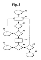
- FIG. 3 shows a first exemplary embodiment of a method sequence according to the invention.
- an initialization step 40 in which the method according to the invention is started for example at a Start of the passenger vehicle 1, is further branched to a determination step 41.
- the radar device 8, the camera device 9, the exterior mirror cameras 13, 15 and the distance sensors 16, 17, 19 are queried as to whether a critical situation exists. This is checked in a subsequent first test step 42. If there is no critical situation, then branching back to the determination step 41. On the other hand, if it is determined that a critical situation exists, a further branch is made to a second checking step 43. In the second checking step 43, it is checked whether the critical situation determined by the determining step 41 has a high priority.
- third test step 46 it is checked whether the determined attention is low or high. If the determined attention is low, it branches to an output step 47 in which a warning is issued in the same way as in the output step 44. On the other hand, in the third test step 46 If the driver's attention for the corresponding area has been determined to be high, a further branch is made to a fourth test step 48. In the fourth test step 48, it is checked whether the fourth test step 48 has already been achieved repeatedly for the same, determined, critical situation. This is the case, for example, when a driver exceeds the road boundary with the vehicle in the longer term. In this case, it branches to an output step 49 in which a warning as well as the output step 44 is output.
- the fourth checking step 48 if the fourth checking step 48 reveals that a critical situation ascertained in the determining step 41 is reached for the first time, then branching is made to the determining step 41 and subsequently it is checked whether the critical situation still exists.
- a counter not shown in FIG. 3, is incremented, which is reset after a predetermined time, if the critical situation has not recurred or not consists.
- the attention determination step 45 from FIG. 3 is shown in detail.
- a first test step 51 it is checked in a first test step 51 whether the physiological sensors 21 give an indication that the driver is tired. If fatigue is detected, for example, from a low body temperature or a low pulse beat, the procedure branches to a first setting step 52, which sets the driver's attention low.
- the memory unit 31 can store non-volatile specific physiological characteristics of the driver.
- the physiological data is in a denomination range If there is no conclusion as to driver fatigue, then a further branch is made to a second test step 53. In the second test step 53 it is determined based on an evaluation of the determined by the camera device 5 image of the driver, whether the driver is tired.
- a branch is made to a second setting step 54, in which it is likewise established that the driver's attention is low. Otherwise, a further branch is made to a third checking step 55, in which it is checked whether the mobile telephone is activated. If so, low driver attention is also set in a third commit step 56. If, on the other hand, it is determined that the mobile telephone is not being used, a further branch is made to a fourth checking step 57, in which it is checked whether an increased frequency of operation of the remaining electrical devices 22, for example the navigation device or the car radio device, has taken place within a predetermined time interval.
- a further branching step 58 in which a low attention of the driver is determined. If no increased operating frequency is detected, a further branch is made to a fifth checking step 59, in which it is checked whether the driver's line of sight coincides with the direction which is important for the critical situation determined in the determining step 41. If, for example, the critical situation is a reduced distance of the vehicle from an obstacle located behind it, in the event that the driver also looks backwards, the driver will receive a high level of attention in a fifth setting step 60 following the fifth checking step 59 determined. On the other hand, if it is determined that the viewing direction important for the critical situation does not coincide with the driver's line of vision, then the route branches to a sixth setting step 61 where a low driver's attention is detected.
- an output of the warning relevant to a direction in which the driver is not looking toward a warning of a direction in which the driver is watching, is issued first has directed. This ensures that alerts are issued first for critical situations that are not in the driver's field of vision.
Description
Die Erfindung geht aus von einem Verfahren zur Warnung eines Fahrzeugführers nach der Gattung des Hauptanspruchs. Es ist bekannt, einen Fahrer durch Warnanzeigen, die vorzugsweise in einem Kombiinstrument vor dem Fahrer angeordnet sind, vor Fehlfunktionen eines Fahrzeugs oder vor sonstigen, gefährlichen kritischen Situationen zu warnen. Hierzu ist bekannt, für die Warnanzeigen mittels Sensoren Fahrzeugfunktionen auszuwerten, z.B. die Dicke der Bremsbeläge, die Kühlwassertemperatur, den Öldruck oder die Außentemperatur. Weiterhin sind Sensoren bekannt, die Hindernisse im Fahrweg vor oder hinter dem Fahrzeug erkennen, so z.B. eine Einparkhilfe oder ein ACC-System (Adaptiv Cruise Control), die mittels elektromagnetischen oder akustischen Sensoren Abstände zu Hindernissen erfassen. Weiterhin sind Verfahren bekannt, bei denen mittels einer Kamera der Fahrweg und die Umgebung des Fahrzeugs überwacht werden, um z.B. ein Verlassen des Fahrwegs durch das Fahrzeug zu detektieren. Ferner sind Systeme bekannt, mit denen ein Fahrer dahingehend überwacht wird, ob er ermüdet oder einschläft. Nachteilig bei diesen Warnvorrichtungen ist, dass ein Fahrer einerseits vor gefährlichen Situationen mehrfach gewarnt wird und andererseits auch bei möglichen Gefahrensituationen gewarnt wird, die der Fahrer längst erkannt hat oder die keine Gefahrensituation für das Fahrzeug darstellen. Liegt z.B. ein Stück Papier oder ein Stück Holz auf der Fahrbahn und weicht der Fahrer kurz über eine Begrenzung der Fahrbahnmarkierung aus, wird er einerseits möglicherweise vor dem Hindernis und andererseits bei dem Überfahren der Fahrbahnbegrenzungsmarkierung gewarnt, obwohl er das Hindernis einerseits gesehen hat sowie die Fahrbahnmarkierung willentlich überfahren hat und andererseits auch durch ein Überfahren des Papiers oder Holzstücks kein Schaden an dem Fahrzeug entstanden wäre. Folglich kann ein Fahrer mit unnötigen Warnungen überhäuft werden, die seine Reizschwelle gegenüber Warnungen durch die Fahrzeugelektronik insgesamt absenken. Eine möglicherweise wichtige Warnung nimmt ein Fahrer dann gegebenenfalls nicht mehr wahr, sodass er trotz eines geeigneten Warnsystems in einer wirklichen Gefahrensituation nicht mehr auf eine Warnung reagiertThe invention is based on a method for warning a vehicle driver according to the preamble of the main claim. It is known to warn a driver by warning displays, which are preferably arranged in an instrument cluster in front of the driver, against malfunction of a vehicle or other dangerous critical situations. For this purpose, it is known to evaluate vehicle functions for the warning displays by means of sensors, for example the thickness of the brake linings, the cooling water temperature, the oil pressure or the outside temperature. Furthermore, sensors are known which detect obstacles in the track in front of or behind the vehicle, such as a parking aid or an ACC system (Adaptive Cruise Control), which detect distances to obstacles by means of electromagnetic or acoustic sensors. Furthermore, methods are known in which by means of a camera, the track and the surroundings of the vehicle are monitored, for example, to detect a departure from the track through the vehicle. Furthermore, systems are known which monitor a driver for fatiguing or falling asleep. A disadvantage of these warning devices is that a driver is on the one hand warned of dangerous situations several times and on the other hand is warned in possible dangerous situations that the driver long ago has detected or that represent no dangerous situation for the vehicle. For example, if a piece of paper or a piece of wood on the road and the driver differs briefly over a boundary of the lane marking, he is warned on the one hand before the obstacle and on the other hand when crossing the lane boundary marker, although he has seen the obstacle on the one hand and the lane marking has overrun deliberately and on the other hand also by crossing the paper or piece of wood no damage to the vehicle would have arisen. As a result, a driver may be overwhelmed with unnecessary warnings that lower his or her threshold to warnings from the vehicle electronics as a whole. A possibly important warning may then no longer be perceived by a driver, so that he no longer reacts to a warning despite a suitable warning system in a real danger situation
Aus der gattungsbildenden
Aus der
Das erfindungsgemäße Verfahren mit den Merkmalen des Hauptanspruchs hat demgegenüber den Vorteil, dass vor der Ausgabe einer Warnung eine Aufmerksamkeit des Fahrzeugführers ermittelt wird und dass eine Warnung vor einer kritischen Situation nur bei einer niedrigen Aufmerksamkeit des Fahrers ausgegeben wird. Hierdurch wird ein Fahrer nur vor solchen Gefahren gewarnt, die seiner Aufmerksamkeit wahrscheinlich entgehen, sodass die Anzahl überflüssiger Warnungen reduziert wird. Eingehende Warnungen werden daher von dem Fahrer beachtet, sodass eine effiziente Ausgabe von Warnungen mit einer hohen Akzeptanz durch den Fahrer erreicht wird. Indem Warnungen nur bei einer niedrigen Aufmerksamkeit des Fahrers ausgegeben werden, wird ein Fahrer die ausgegebenen Warnungen vielmehr besonders beachten.The inventive method with the features of the main claim has the advantage that prior to the issue of a warning attention of the driver is determined and that issued a warning of a critical situation only at a low attention of the driver becomes. This will alert a driver only to hazards that are likely to escape his attention, reducing the number of superfluous warnings. Incoming warnings are therefore observed by the driver, so that an efficient issuance of warnings with a high level of driver acceptance is achieved. By issuing warnings only with low driver attention, a driver will pay particular attention to the warnings issued.
Durch die in den Unteransprüchen aufgeführten Maßnahmen sind vorteilhafte Weiterbildungen und Verbesserungen des im Hauptanspruch angegebenen Verfahrens möglich. Besonders vorteilhaft ist, durch eine Kameravorrichtung ein Bild eines Fahrers zu erfassen und mittels einer Verarbeitung durch eine Recheneinheit auf die Aufmerksamkeit des Fahrers zu schließen, da hierdurch im Gegensatz zu indirekten Methoden, direkt die Aufmerksamkeit und insbesondere der Wachzustand des Fahrers ermittelt wird. Hierbei ist besonders vorteilhaft, die Blickrichtung, die Lidschlagsfrequenz und/oder die Kopfposition des Fahrers zu ermitteln. Eine hohe Lidschlagsfrequenz bzw. geschlossene Augenlider lassen ebenso wie ein gesenkter Kopf auf eine Ermüdung des Fahrers schließen. Vorteilhaft ist dabei, die Blickrichtung dahingehend auszuwerten, dass lediglich der Richtung, in die der Fahrer schaut, eine hohe Aufmerksamkeit zugewiesen wird, während den übrigen Richtungen, in die er nicht schaut und die also außerhalb seines Blickfelds liegen, eine niedrige Aufmerksamkeit zugewiesen wird. Schaut folglich beim Rückwärtsfahren ein Fahrer nach vorne und wird z.B. von einer Abstandsmessungsvorrichtung ein zu niedriger, rückwärtiger Abstand des Fahrzeugs zu einem Hindernis erfasst, so erfolgt neben einer optischen Warnung z.B. mittels einer Leuchtdiodenanzeige sehr früh eine zusätzliche akustische Warnung, z.B. bereits bei einem Abstand von 2 m. Bei einem Fahrer, dessen Blick im Fahrzeug nach hinten gerichtet ist, erfolgt erst bei einem rückwärtigen Abstand von vorzugsweise 50 cm eine zusätzliche, akustische Warnung.The measures listed in the dependent claims advantageous refinements and improvements of the main claim method are possible. It is particularly advantageous to detect a driver's image by means of a camera device and to draw attention to the driver's attention by means of processing by an arithmetic unit, since in contrast to indirect methods, the attention and, in particular, the waking state of the driver are determined directly. It is particularly advantageous to determine the line of sight, the blinking frequency and / or the head position of the driver. A high eyelid frequency or closed eyelids, as well as a lowered head, indicate fatigue for the driver. It is advantageous to evaluate the viewing direction so that only the direction in which the driver looks, a high attention is assigned, while the other directions in which he does not look and therefore lie outside his field of view, a low attention is assigned. Consequently, when reversing, a driver looks ahead and is e.g. detected by a distance measuring device too low, rearward distance of the vehicle to an obstacle, so takes place in addition to an optical warning, for. by means of a light-emitting diode display very early an additional audible warning, e.g. already at a distance of 2 m. In a driver whose view is directed in the vehicle to the rear, takes place only at a rear distance of preferably 50 cm, an additional audible warning.
Ferner ist vorteilhaft, insbesondere bei mehreren gleichzeitig auszugebenden Warnungen, die Warnung vor einer kritischen Situation, die im Blickfeld des Fahrers liegt, erst nach einer Warnung vor einer kritischen Situation auszugeben, die außerhalb des Blickfelds des Fahrers liegt.Furthermore, it is advantageous, in particular in the case of a plurality of warnings to be output simultaneously, to issue the warning of a critical situation which is within the driver's field of vision only after a warning of a critical situation that is outside the field of vision of the driver.
Denn eine kritische Situation in seinem Blickfeld hat der Fahrer wahrscheinlich bereits ohne eine ausgegebene Warnung erfasst.Because a critical situation in his field of vision, the driver has probably already detected without an issued warning.
Weiterhin ist vorteilhaft, die Aufmerksamkeit eines Fahrers von der Bedienung im Fahrzeug angeordneter Geräte abhängig zu machen. Wird z.B. festgestellt, dass ein Fahrer eine Navigationsvorrichtung programmiert oder eine Autoradioeinheit bedient, so wird ihm für diesen Zeitraum eine niedrigere Aufmerksamkeit zugewiesen. Gleiches gilt für den Fall, dass das im Fahrzeug angeordnete Telefon benutzt wird.Furthermore, it is advantageous to make a driver's attention dependent on the operation of the vehicle arranged devices. If e.g. If a driver determines that a navigation device is being programmed or is operating a car radio unit, he will be given less attention for that period. The same applies in the event that the arranged in the vehicle phone is used.
Weiterhin ist vorteilhaft, über Sensoren einen Müdigkeitszustand des Fahrers zu ermitteln, indem vorzugsweise die Körpertemperatur und/oder Pulsfrequenz bestimmt wird. Auch über diese ermittelten, physiologischen Daten ist eine direkte Auskunft über die Aufmerksamkeit des Fahrers möglich.Furthermore, it is advantageous to determine a driver's state of tiredness via sensors, by determining preferably the body temperature and / or pulse frequency. Also via this determined, physiological data is a direct information about the driver's attention possible.
Um gerade einen Fahrer mit niedriger Aufmerksamkeit erreichen zu können, wird eine Warnung dabei in vorteilhafter Weise akustisch ausgegeben, da so die Blickrichtung des Fahrers nicht auf eine Warnanzeige gerichtet sein muss.In order to be able to reach a driver with low attention, a warning is emitted acoustically in an advantageous manner since the driver's line of sight does not have to be directed to a warning display.
Ausführungsbeispiele der Erfindung sind in der Zeichnung dargestellt und in der nachfolgenden Beschreibung näher erläutert. Es zeigen Figur 1 die Anordnung von Sensoren zur Durchführung des erfindungsgemäßen Verfahrens in einem Fahrzeug, Figur 2 eine Schaltung erfindungsgemäßer Sensoren an eine Recheneinheit mit einer Ausgabeeinheit zur Durchführung des erfindungsgemäßen Verfahrens, Figur 3 ein Ausführungsbeispiel für einen Ablauf des erfindungsgemäßen Verfahrens und Figur 4 ein Ausführungsbeispiel für einen Auswerteschritt des erfindungsgemäßen Verfahrens.Embodiments of the invention are illustrated in the drawings and explained in more detail in the following description. 1 shows the arrangement of sensors for carrying out the method according to the invention in a vehicle, Figure 2 shows a circuit according to the invention sensors to a computing unit with an output unit for carrying out the method according to the invention, Figure 3 shows an embodiment of a sequence of the method according to the invention and Figure 4 shows an embodiment for an evaluation step of the method according to the invention.
Das erfindungsgemäße Verfahren kann in einer Vielzahl von Fahrzeugen eingesetzt werden, so z.B. in Schienenfahrzeugen, in Flugzeugen, in Schiffen und in Kraftfahrzeugen. Ferner ist auch eine Verwendung bei einer Fernbedienung von Fahrzeugen oder anderen Maschinen von einem Kommandostand aus möglich. Im Folgenden wird das erfindungsgemäße Verfahren anhand der Ausführung in einem Kraftfahrzeug erläutert. Eine Kombination von Sensoren, die zu einer Erfassung von kritischen Situationen für das Fahrzeug dienen, kann hierbei beliebig gewählt werden. In dem angeführten Ausführungsbeispiel wurde eine vorteilhafte Kombination von Sensoren ausgewählt, bei der jedoch je nach Ausführung des Fahrzeugs weitere Sensoren ergänzt oder auch aus Kostengründen Sensoren weggelassen werden können.The method of the invention can be used in a variety of vehicles, e.g. in rail vehicles, in airplanes, in ships and in motor vehicles. Furthermore, a use in a remote control of vehicles or other machines from a command post is possible. The method according to the invention will be explained below with reference to the embodiment in a motor vehicle. A combination of sensors, which serve to detect critical situations for the vehicle, can be chosen arbitrarily. In the cited embodiment, an advantageous combination of sensors was selected, however, in which, depending on the design of the vehicle, additional sensors can be added or sensors can also be omitted for reasons of cost.
In der Figur 1 ist ein Personenkraftfahrzeug 1 mit einer Windschutzscheibe 2, einem Fahrzeugdach 3 und einer Rückscheibe 4 in einer Aufsicht auf das Fahrzeug dargestellt. In dem Fahrzeugdach 3 ist eine Kameravorrichtung 5 angeordnet, die unterhalb des Fahrzeugdachs 3 durch das Fahrzeugdach 3 verdeckt und daher gestrichelt in der Figur 1 eingezeichnet ist. An einer Vorderseite 6 des Fahrzeugs ist hinter einer Kühlerabdeckung 7 eine Radarvorrichtung 8 und eine Kameravorrichtung 9 angeordnet. An einer linken Seitenfläche 10 des Fahrzeugs ist ein linker Außenspiegel 12 mit einer ersten Außenspiegelkamera 13 angeordnet. An einer rechten Seitenfläche 11 ist ein rechter Außenspiegel 14 mit einer zweiten Außenspiegelkamera 15 angeordnet. Ferner ist an der linken Seitenfläche 10 ein Abstandssensor 16 und an der rechten Seitenfläche 11 ein Abstandssensor 17 angeordnet. In einer Rückseite 18 des Fahrzeugs sind rückwärtige Abstandssensoren 19 angeordnet. Unterhalb der Windschutzscheibe 2 ist vor einem Fahrer ein Lenkrad 20 mit physiologischen Sensoren 21 angeordnet, die sich in einem Griffbereich des Lenkrads 20 befinden. Zwischen einem Fahrer und einem Beifahrer sind in einem mittleren Bereich des Fahrzeugs elektrische Geräte 22 angeordnet. Im Bereich des Dashboards ist gestrichelt eine Recheneinheit 23 eingezeichnet, die der Auswertung der in dem Personenkraftfahrzeug 1 angeordneten Sensoren dient. Eine Verbindung von der Recheneinheit 23 zu den einzelnen Sensoren ist in der Figur 1 nicht dargestellt. Eine Ausgabe von Warnungen erfolgt über Lautsprecher 24, vorzugsweise über Lautsprecher eines Autoradios, und/oder über eine Anzeige 25, die vorzugsweise in einem Kombiinstrument vor dem Fahrer angeordnet ist.1 shows a
Die physiologischen Sensoren 21 werden während des Steuerns des Personenkraftfahrzeugs 1 bei einer Berührung des Lenkrads 20 von einem Fahrer berührt, wobei eine Pulsfrequenz vorzugsweise über eine kapazitive Messung und die Körpertemperatur vorzugsweise über eine Infrarotmessung bestimmt wird. Diese Daten werden anschließend an die Recheneinheit 23 weitergeleitet, in der eine Speichereinheit mit Grenzwerten angeordnet ist. Die Recheneinheit 23 vergleicht die Daten der physiologischen Sensoren mit den gespeicherten Grenzwerten und legt in Abhängigkeit von dem Vergleich fest, ob der Fahrer wach oder schläfrig ist. Ist der Fahrer schläfrig, so wird ihm eine niedrigere Aufmerksamkeit zugewiesen. Andernfalls wird anhand dieses Kriteriums keine niedrige Aufmerksamkeit des Fahrers festgestellt. Weiterhin wird ein Bild des Fahrers von der Kameravorrichtung 5 aufgenommen und an die Recheneinheit 23 weitergeleitet. Wird nun vorzugsweise durch den Vergleich mehrerer Bilder festgestellt, dass der Fahrer entweder seine Augen geschlossen hat, die Lidschlagsfrequenz sehr hoch ist oder dass der Kopf des Fahrers gesenkt ist, so wird eine Aufmerksamkeit des Fahrers als niedrig ermittelt. Weiterhin wird aus der Kopfposition des Fahrers eine Blickrichtung des Fahrers ermittelt. Für alle anderen Richtungen außer der Blickrichtung des Fahrers, die das von dem Fahrer wahrnehmbare Blickfeld zumindest nahezu vollständig einschließt, wird dabei die Aufmerksamkeit des Fahrers als eine niedrige Aufmerksamkeit festgelegt. Für die Blickrichtung des Fahrers kann eine Aufmerksamkeit festgelegt werden, sofern nicht z.B. eine zuvor festgestellte Ermüdung des Fahrers dem entgegensteht. In einem bevorzugten Ausführungsbeispiel wird die Aufmerksamkeit des Fahrers digital zwischen "hoher Aufmerksamkeit" und "niedrigerer Aufmerksamkeit" festgelegt. Weiterhin ist auch möglich, die Größe der Aufmerksamkeit weiter zu unterteilen oder auf einer kontinuierlichen Skala festzulegen. Die Aufmerksamkeit des Fahrers wird zunächst für den Fahrer insgesamt und außerdem für verschiedene mögliche Blickrichtungen des Fahrers jeweils einzeln festgelegt. Wird z.B. über die physiologischen Sensoren 21 oder mittels Bildauswertung durch die Kameravorrichtung festgestellt, dass der Fahrer schläft, so kann die Aufmerksamkeit für keine der Blickrichtungen hoch sein. Wird dagegen festgestellt, dass der Fahrer nicht schläft, so kann die Aufmerksamkeit für maximal eine Blickrichtung des Fahrers hoch sein. Blickrichtungen können in einem bevorzugten Ausführungsbeispiel als die Blickrichtungen "nach vorne" in Richtung der Vorderseite 6, "nach links" in Richtung der linken Seitenfläche 10, "nach rechts" in Richtung der rechten Seitenfläche 11 und "nach hinten" in Richtung der Rückseite 18 des Fahrzeugs festgelegt sein. Weiterhin wird eine Bedienung der elektrischen Geräte 22 erfasst. In einem bevorzugten Ausführungsbeispiel sind die elektrischen Geräte 22 als eine Autoradiovorrichtung, eine Navigationsvorrichtung und eine Mobiltelefoneinheit ausgeführt. Sobald die Mobiltelefoneinheit betätigt wird, wird die Aufmerksamkeit des Fahrers auf einen niedrigen Wert festgelegt. Werden an der Autoradiovorrichtung und an der Navigationsvorrichtung in einem bevorzugten Ausführungsbeispiel in einem Zeitraum von 20 Sekunden mehr als zwei Betätigungen von Bedienelementen erfasst, also eine Bedienfrequenz größer 0,1 Hz, so wird ebenfalls eine niedrige Aufmerksamkeit des Fahrers festgelegt.The
Weitere Sensoren, die Fahrzeugfunktionen wie den Öldruck, die Kühlwassertemperatur oder den Bremskreislauf überwachen sind in der Figur 1 nicht eingezeichnet. Derartige Fahrzeugfehlfunktionen treten im Regelfall sehr selten auf und sind auch im Falle eines aufmerksamen Fahrers für diesen wichtig, da im allgemeinen eine Anzeige lediglich über kleine Warnleuchten in der Anzeige 25 erfolgt. Eine zusätzliche, akustische Warnung wird daher unabhängig von der Aufmerksamkeit des Fahrers über die Lautsprecher 24 ausgegeben. Die Lautsprecher 24 sind dabei in einem bevorzugten Ausführungsbeispiel als Lautsprecher der Autoradiovorrichtung ausgeführt, die ein Teil der elektrischen Geräte 22 ist.Further sensors that monitor vehicle functions such as the oil pressure, the cooling water temperature or the brake circuit are not shown in FIG. As a rule, such vehicle malfunctions occur very rarely and are important for the driver, even in the case of an attentive driver since, in general, an indication is only given via small warning lamps in the
Über die Kameravorrichtung 9 wird der Fahrweg des Fahrzeugs beobachtet. Ein Bild des Fahrwegs wird an die Recheneinheit 23 übermittelt, die feststellt, ob sich das Personenkraftfahrzeug 1 noch auf dem Fahrweg befindet, in dem eine Position von Fahrbahnbegrenzungen und die Position des Personenkraftfahrzeugs 1 zu den Fahrbahnbegrenzungen bestimmt wird. Wird festgestellt, dass der Fahrer aufmerksam ist, so wird lediglich bei einer längeren Überschreitung der Fahrbahnbegrenzungen eine akustische Warnung an den Fahrer ausgegeben. Wird dagegen von der Recheneinheit 23 festgestellt, dass der Fahrer nur kurzzeitig die Fahrbahnbegrenzungen überschreitet, so wird eine Warnung unterdrückt. Die Kameravorrichtung 9 ist neben der Radarvorrichtung 8 hinter der Kühlerabdeckung 7 angeordnet, so dass weder die Kameravorrichtung 9, noch die Radarvorrichtung 8 für einen Betrachter außerhalb des Fahrzeugs sichtbar sind. Die Radarvorrichtung 8 überwacht den Abstand zu einem vorhergehenden Fahrzeug bzw. zu einem vor dem Fahrzeug liegenden Hindernis. Bei einem aufmerksamen Fahrer unterbleibt eine Warnung bis zu einem Abstand von 75 % des sogenannten "Halben Tachoabstandes", bei dem aus der gefahrenen Geschwindigkeit in Kilometern durch Division durch 2 ein vorzugsweise einzuhaltender Abstand ermittelt wird. Bei 100 km/h sind dies z.B. 50 m. Wird von der Recheneinheit 23 festgestellt, dass der Fahrer aufmerksam ist, erfolgt eine Warnung erst bei einem Unterschreiten eines Abstandes von 38 m, sofern nicht durch die Recheneinheit 23 der Abstand automatisch durch ein Einwirken auf den Antriebsstrang bzw. auf die Bremsen gesteuert wird. Wird dagegen eine geringere Aufmerksamkeit des Fahrers festgestellt, so wird bereits bei einem Unterschreiten eines Abstands von 50 m der Fahrer gewarnt. Unter anderem wird eine verringerte Aufmerksamkeit festgestellt, wenn der Fahrer nicht in Richtung der Vorderseite 6 des Fahrzeugs schaut. Die erste Außenspiegelkamera und die zweite Außenspiegelkamera 15 dienen der Überwachung eines sogenannten toten Winkels des Fahrzeugs, also einem Bereich, der nicht in den Außenspiegeln 12 bzw. 14 des Fahrzeugs für einen Fahrer ersichtlich ist. Wird z.B. durch eine Betätigung eines in Figur 1 nicht dargestellten Blinkerhebels festgestellt, dass ein Fahrer die Fahrbahn wechseln will, und wird von den Außenspiegelkameras 13, 15 ein Fahrzeug in dem jeweiligen, toten Winkel ermittelt, so erfolgt bei einer niedrigen Aufmerksamkeit des Fahrers eine Warnung, insbesondere wenn der Fahrer nicht in Richtung der linken Seitenfläche 10 bzw. der rechten Seitenfläche 11 des Fahrzeugs schaut.About the
Parkt ein Fahrer rückwärts ein, so wird von den Abstandssensoren 16, 17, 19 ein Abstand zu möglichen Hindernissen gemessen. Die Abstandssensoren 16, 17, 19 sind vorzugsweise als Ultraschallsensoren ausgeführt, können aber ferner auch als elektromagnetische Sensoren, z.B. Mikrowellensensoren, ausgeführt sein. Wird eine hohe Aufmerksamkeit des Fahrers in Richtung der Rückseite 18 mittels Auswertung seiner Blickrichtung festgestellt, so erfolgt eine Warnung vorzugsweise erst bei einem von den Abstandssensoren 16, 17, 19 zu einem Hindernis ermittelten Abstand von 50 cm oder weniger. Wird dagegen eine niedrige Aufmerksamkeit festgestellt oder wird festgestellt, dass der Fahrer nach vorne sieht, so wird eine Warnung an den Fahrer bei einem bevorzugten Ausführungsbeispiel bereits bei einer Unterschreitung von einem Abstand von beispielsweise 2 m zu einem von den Abstandssensoren 16, 17, 19 ermittelten Hindernis ausgegeben.If a driver parks backwards, the
Kritische Situationen für das Fahrzeug können z.B. akute Fahrzeugdefekte, so z.B. ein Defekt im Bremssystem, ein geringer Abstand des Fahrzeugs zu einem Hindernis, eine Überschreitung einer Fahrbahnbegrenzungsmarkierung oder ein zu geringer Abstand zu einem vorausfahrenden oder zu einem nebenher fahrenden Fahrzeug sein. Eine Ermittlung erfolgt jeweils durch geeignete Sensoren.Critical situations for the vehicle may be, for example, acute vehicle defects, such as a defect in the brake system, a small distance of the vehicle to an obstacle, exceeding a lane boundary marking or too short distance to a vehicle in front or to the side. A determination is made in each case by suitable sensors.
In der Figur 2 ist eine Schaltung von Fahrzeugsensoren zu der Recheneinheit 23 dargestellt. In der Recheneinheit 23 ist eine Speichereinheit 31 zum Abspeichern von Grenzwerten angeordnet, mit denen die von den Fahrzeugsensoren ermittelten Werte verglichen werden. Mittels Vergleich zu den in der Speichereinheit 31 abgelegten Grenzwerten wird von der Recheneinheit 23 entschieden, ob der Fahrer aufmerksam ist oder nicht. Legt die Recheneinheit 23 fest, dass eine Warnung ausgegeben wird, so wird der Befehl zur Ausgabe einer Warnung an eine Ausgabeeinheit 32 weitergeleitet. Mittels der Ausgabeeinheit 32 wird eine Warnung an eine Anzeigeeinheit 33 weitergeleitet, in der die Warnung zur Anzeige gelangt. Die Anzeigeeinheit 33 ist vorzugsweise in einer für den Fahrer gut sichtbaren Stelle ausgeführt, z.B. in der Form der Anzeige 25 gemäß der Figur 1. In einem bevorzugten Ausführungsbeispiel wird durch eine Sprachbildungseinheit 34 die Warnung in eine Sprachausgabe umgewandelt, die ebenso wie ein Warnton über einen Lautsprecher 24 ausgegeben wird. Mit der Recheneinheit 23 ist die Kameravorrichtung 5, die Radarvorrichtung 8, die Kameravorrichtung 9, eine erste Außenspiegelkamera 13, eine zweite Außenspiegelkamera 15, die Abstandssensoren 16, 17, 19, die physiologischen Sensoren 21, die elektrischen Geräte 22 und in der Figur 1 nicht dargestellte Fahrzeugsensoren, z.B. eine Kühlmittelkontrolle 35 und eine Bremssystemkontrolle 36 verbunden.FIG. 2 shows a circuit of vehicle sensors to the
In der Figur 3 ist ein erstes Ausführungsbeispiel für einen erfindungsgemäßen Verfahrensablauf dargestellt. Ausgehend von einem Initialisierungsschritt 40, in dem das erfindungsgemäße Verfahren gestartet wird, z.B. bei einem Start des Personenkraftfahrzeugs 1, wird zu einem Ermittlungsschritt 41 weiter verzweigt. In dem Ermittlungsschritt 41 werden die Radarvorrichtung 8, die Kameravorrichtung 9, die Außenspiegelkameras 13, 15 und die Abstandssensoren 16, 17, 19 dahingehend abgefragt, ob eine kritische Situation vorliegt. Dies wird in einem anschließenden ersten Prüfschritt 42 überprüft. Liegt keine kritische Situation vor, so wird zu dem Ermittlungsschritt 41 zurückverzweigt. Wird dagegen festgestellt, dass eine kritische Situation vorliegt, wird zu einem zweiten Prüfschritt 43 weiterverzweigt. In dem zweiten Prüfschritt 43 wird überprüft, ob die dem Ermittlungsschritt 41 ermittelte, kritische Situation eine hohe Priorität aufweist. Dies ist z.B. der Fall, wenn der Abstand der Abstandssensoren 16, 17, 19 geringer als 50 cm ist, wenn das Bremssystem ausgefallen ist, wenn die Kühlwassertemperatur überschritten wird oder wenn der Abstand zu einem vorrausfahrenden Fahrzeug weit unterhalb des halben Tachoabstandes liegt. Wird eine solche kritische Situation festgestellt, liegt eine Warnung hoher Priorität vor. Es wird daher zu einem Ausgabeschritt 44 weiterverzeigt, in dem die Warnung hoher Priorität über die Ausgabeeinheit 32 mittels der Lautsprecher 24 und der Anzeigeeinheit 33 ausgegeben wird. Wird dagegen in dem zweiten Prüfschritt 43 festgestellt, dass keine solche Warnung hoher Priorität vorliegt, wird zu dem Aufmerksamkeitsermittlungsschritt 45 weiterverzweigt, in dem die Aufmerksamkeit des Fahrers über den für die in dem Ermittlungsschritt 41 ermittelte kritische Situation relevanten Bereich bestimmt wird. In dem anschließenden, dritten Prüfschritt 46, wird überprüft, ob die ermittelte Aufmerksamkeit niedrig oder hoch ist. Ist die ermittelte Aufmerksamkeit niedrig, so wird zu einem Ausgabeschritt 47 weiterverzweigt, in dem eine Warnung in gleicher Weise wie bei dem Ausgabeschritt 44 ausgegeben wird. Wird dagegen in dem dritten Prüfschritt 46 festgestellt, dass die Aufmerksamkeit des Fahrers für den entsprechenden Bereich hoch ist, so wird zu einem vierten Prüfschritt 48 weiterverzweigt. In dem vierten Prüfschritt 48 wird überprüft, ob für die gleiche, ermittelte, kritische Situation der vierte Prüfschritt 48 bereits mehrfach erreicht wurde. Dies ist z.B. dann der Fall, wenn ein Fahrer längerfristig die Fahrbahnbegrenzung mit dem Fahrzeug überschreitet. In diesem Fall wird zu einem Ausgabeschritt 49 weiterverzweigt, in dem eine Warnung ebenso wie in dem Ausgabeschritt 44 ausgegeben wird. Ergibt dagegen der vierte Prüfschritt 48, dass eine in dem Ermittlungsschritt 41 ermittelte, kritische Situation das erste Mal erreicht wird, so wird zu dem Ermittlungsschritt 41 weiterverzweigt und im weiteren Verlauf wird überprüft, ob die kritische Situation weiterhin besteht. Um ein wiederholtes Auftreten einer kritischen Situation ermitteln zu können, wird in dem vierten Prüfschritt 48 für kritische Situationen ein in der Figur 3 nicht dargestellter Zähler inkrementiert, der nach einer vorgegebenen Zeit zurückgesetzt wird, wenn die kritische Situation nicht erneut aufgetreten ist bzw. nicht mehr besteht.FIG. 3 shows a first exemplary embodiment of a method sequence according to the invention. Starting from an
In der Figur 4 ist der Aufmerksamkeitsermittlungsschritt 45 aus der Figur 3 im Detail dargestellt. Ausgehend von einem Initialisierungsschritt 50 wird in einem ersten Prüfschritt 51 geprüft, ob die physiologischen Sensoren 21 einen Hinweis darauf geben, dass der Fahrer ermüdet ist. Wird eine Ermüdung festgestellt, z.B. anhand einer niedrigen Körpertemperatur oder eines niedrigen Pulsschlages, wird zu einem ersten Festlegungsschritt 52 weiterverzweigt, dem die Aufmerksamkeit des Fahrers als niedrig festgelegt wird. In einer bevorzugten Ausführung sind hierbei der Speichereinheit 31 spezielle physiologische Kenndaten des Fahrers nicht flüchtig ablegbar. Wird dagegen festgestellt, dass die physiologischen Daten in einem Nennwertbereich liegen und keinen Rückschluss auf eine Müdigkeit des Fahrers geben, so wird zu einem zweiten Prüfschritt 53 weiterverzweigt. In dem zweiten Prüfschritt 53 wird anhand einer Auswertung des von der Kameravorrichtung 5 ermittelten Bilds des Fahrers festgestellt, ob der Fahrer ermüdet ist. Dies erfolgt vorzugsweise über die Auswertung der Lidschlagsfrequenz bzw. über eine Auswertung, ob die Augen des Fahrers geschlossen sind. Wird dies festgestellt, so wird zu einem zweiten Festlegungsschritt 54 verzweigt, in dem ebenfalls festgelegt wird, dass die Aufmerksamkeit des Fahrers niedrig ist. Andernfalls wird zu einem dritten Prüfschritt 55 weiterverzweigt, in dem überprüft wird, ob das Mobiltelefon aktiviert ist. Ist dies der Fall, so wird ebenfalls eine niedrige Aufmerksamkeit des Fahrers in einem dritten Festlegungsschritt 56 festgelegt. Wird dagegen festgestellt, dass das Mobiltelefon nicht benutzt wird, so wird zu einem vierten Prüfschritt 57 weiterverzweigt, in dem überprüft wird, ob eine erhöhte Bedienungshäufigkeit der übrigen elektrischen Geräte 22, so z.B. der Navigationsvorrichtung oder der Autoradiovorrichtung, in einem vorgegebenen Zeitintervall erfolgt ist. Wird festgestellt, dass eine solche erhöhte Bedienfrequenz erfolgt ist, so wird ebenfalls zu einem vierten Feststellungsschritt 58 weiterverzweigt in dem eine niedrige Aufmerksamkeit des Fahrers ermittelt wird. Wird keine erhöhte Bedienfrequenz festgestellt, so wird zu einem fünften Prüfschritt 59 weiterverzweigt, in dem überprüft wird, ob die Blickrichtung des Fahrers mit der Richtung übereinstimmt, die für die im Ermittlungsschritt 41 ermittelte kritische Situation wichtig ist. Ist die kritische Situation z.B. ein verringerter Abstand des Fahrzeugs zu einem hinter ihm befindlichen Hindernis, so wird in dem Fall, dass der Fahrer auch nach hinten schaut, eine hohe Aufmerksamkeit des Fahrers in einem an den fünften Prüfschritt 59 anschließenden fünften Festlegungsschritt 60 ermittelt. Wird dagegen festgestellt, dass die Blickrichtung, die für die kritische Situation wichtig ist, mit der Blickrichtung des Fahrers nicht übereinstimmt, so wird zu einem sechsten Festlegungsschritt 61 weiterverzweigt, in dem eine niedrige Aufmerksamkeit des Fahrers ermittelt wird.In FIG. 4, the
Gehen in der Ausgabeeinheit 32 mehrere Warnungen zur Ausgabe ein, so erfolgt in einem bevorzugten Ausführungsbeispiel eine Ausgabe derjenigen Warnung zuerst, die für eine Richtung relevant ist, in die der Fahrer nicht schaut gegenüber einer Warnung für eine Richtung, in die der Fahrer gerade seinen Blick gerichtet hat. Hierdurch wird gewährleistet, dass Warnungen für kritische Situationen zuerst ausgegeben werden, die sich nicht in einem Blickfeld des Fahrers befinden.In the
Claims (7)
- Method for warning a driver of a vehicle, a critical situation being sensed by vehicle sensors and the attentiveness of the driver being determined, a warning about the critical situation being issued as a function of the attentiveness of the driver the driver operating and/or using devices arranged in the vehicle being sensed, and a low level of attentiveness of the driver being determined if one of the devices is used and/or if a predefined value of an operating frequency of one of the devices is exceeded, characterized in that a warning is issued only if there is a low level of attentiveness of the driver.
- Method according to Claim 1, characterized in that a camera device senses an image of the driver, in that the image is processed by the computing unit and the attentiveness of the driver is determined from the image.
- Method according to Claim 2, characterized in that the attentiveness of the driver is determined by means of the viewing direction, the frequency of blinking and/or the position of the head.
- Method according to one of Claims 2 and 3, characterized in that a high level of attentiveness is assigned to the viewing direction of the driver, and in that a low level of attentiveness is assigned to the other directions.
- Method according to one of the preceding claims, characterized in that the warning is issued at least audibly.
- Device for carrying out the method according to one of the preceding claims with vehicle sensors and with at least one device which is arranged in the vehicle, the device being configured in such a way that the vehicle sensors sense a critical situation, that the attentiveness of the driver is determined, that a warning about the critical situation is issued as a function of the attentiveness of the driver, that the driver operating and/or using at least one device is sensed, and that a low level of attentiveness of the driver is determined if one of the devices is used and/or if a predefined value of an operating frequency of one of the devices is exceeded, characterized in that the device issues a warning only if there is a lower level of attentiveness of the driver.
- Device according to Claim 6, characterized in that the vehicle sensors are a parking aid device, a device for maintaining inter-vehicle distance, a device for detecting obstacles in a blind angle and/or a device for monitoring the boundaries of the carriageway, and in that the device which is arranged in the vehicle is a car radio, a navigation device or a mobile telephone.
Applications Claiming Priority (3)
| Application Number | Priority Date | Filing Date | Title |
|---|---|---|---|
| DE10039795 | 2000-08-16 | ||
| DE10039795A DE10039795C2 (en) | 2000-08-16 | 2000-08-16 | Method for warning a driver of a vehicle |
| EP01119211A EP1182089B2 (en) | 2000-08-16 | 2001-08-09 | Vehicle driver warning procedure |
Related Parent Applications (1)
| Application Number | Title | Priority Date | Filing Date |
|---|---|---|---|
| EP01119211A Division EP1182089B2 (en) | 2000-08-16 | 2001-08-09 | Vehicle driver warning procedure |
Publications (2)
| Publication Number | Publication Date |
|---|---|
| EP1557321A1 EP1557321A1 (en) | 2005-07-27 |
| EP1557321B1 true EP1557321B1 (en) | 2007-07-18 |
Family
ID=7652459
Family Applications (2)
| Application Number | Title | Priority Date | Filing Date |
|---|---|---|---|
| EP01119211A Expired - Lifetime EP1182089B2 (en) | 2000-08-16 | 2001-08-09 | Vehicle driver warning procedure |
| EP05101988A Expired - Lifetime EP1557321B1 (en) | 2000-08-16 | 2001-08-09 | Vehicle driver warning procedure |
Family Applications Before (1)
| Application Number | Title | Priority Date | Filing Date |
|---|---|---|---|
| EP01119211A Expired - Lifetime EP1182089B2 (en) | 2000-08-16 | 2001-08-09 | Vehicle driver warning procedure |
Country Status (2)
| Country | Link |
|---|---|
| EP (2) | EP1182089B2 (en) |
| DE (3) | DE10039795C2 (en) |
Families Citing this family (81)
| Publication number | Priority date | Publication date | Assignee | Title |
|---|---|---|---|---|
| DE10223210A1 (en) * | 2002-05-24 | 2003-12-04 | Stotz Feinmesstechnik Gmbh | Vehicle driver alerting method for alerting a driver upon falling to sleep momentarily monitors the duration of the driver's eyelids closing prior to triggering a warning signal |
| DE10238324B4 (en) * | 2002-08-21 | 2014-02-13 | Volkswagen Ag | Method and device for monitoring the driver of a motor vehicle |
| DE10240018B4 (en) * | 2002-08-27 | 2016-09-15 | Volkswagen Ag | Method and device for generating a warning signal before an emergency measure of a driver assistance system of a vehicle |
| DE10241922A1 (en) * | 2002-09-10 | 2004-03-18 | Bayerische Motoren Werke Ag | Driver assist circuit for motor vehicle, has sensors for vehicle surroundings data and driver display in real time |
| DE10244205A1 (en) | 2002-09-23 | 2004-03-25 | Robert Bosch Gmbh | Vehicle collision prevention method for preventing collision between motor vehicles uses sensors to detect a vehicle's surroundings and its amount of movement |
| WO2004044861A1 (en) * | 2002-11-13 | 2004-05-27 | Hannah Collip | A vehicle interior air treatment apparatus |
| DE10305935A1 (en) * | 2003-02-13 | 2004-08-26 | Valeo Schalter Und Sensoren Gmbh | Device for detecting objects in the environment of a motor vehicle |
| DE10322458A1 (en) | 2003-05-16 | 2004-12-02 | Daimlerchrysler Ag | Method and device for influencing the stress of a driver in a motor vehicle |
| DE10339647A1 (en) | 2003-08-28 | 2005-03-24 | Robert Bosch Gmbh | Device for driver warning |
| DE10340870A1 (en) * | 2003-09-04 | 2005-04-28 | Siemens Ag | Controlling output of messages in vehicle information system, by outputting messages based on priority and on criteria received from information system |
| DE10343683A1 (en) * | 2003-09-20 | 2005-04-21 | Daimler Chrysler Ag | Information system for motor vehicles |
| DE102004012475A1 (en) * | 2004-03-15 | 2005-10-06 | Carl Zeiss Jena Gmbh | Indicator device e.g. head-up-display indicator device, for vehicle, has virtual image generating optics and IR light source used with camera to monitor driver activity |
| DE102004022113A1 (en) * | 2004-05-05 | 2005-11-24 | Robert Bosch Gmbh | Monitoring a car trailer with a reversing camera |
| DE102004039305A1 (en) * | 2004-08-12 | 2006-03-09 | Bayerische Motoren Werke Ag | Device for evaluating the attention of a driver in a collision avoidance system in motor vehicles |
| DE102004047136A1 (en) * | 2004-09-27 | 2006-04-13 | Daimlerchrysler Ag | Learning reactions of vehicle driver involves correcting actual reaction on vehicle side into reaction usually recognized as desired reaction when driver tiredness detected |
| DE102004048011A1 (en) | 2004-10-01 | 2006-04-06 | Robert Bosch Gmbh | Method and device for driver assistance |
| DE102004048009A1 (en) * | 2004-10-01 | 2006-04-06 | Robert Bosch Gmbh | Method and device for driver assistance |
| DE102004054472B3 (en) * | 2004-11-11 | 2006-03-16 | Bayerische Motoren Werke Ag | Driver assistance system |
| DE102005010230B4 (en) * | 2005-03-05 | 2008-06-19 | Daimler Ag | Method for outputting help information |
| DE102005010229A1 (en) * | 2005-03-05 | 2006-09-14 | Daimlerchrysler Ag | Auxiliary information displaying method for road vehicle`s navigation system, involves finding information and display sequence based on actual situation and activated driver assisting system, and displaying information based on sequence |
| DE102005018688A1 (en) * | 2005-04-22 | 2006-10-26 | Bayerische Motoren Werke Ag | Driver assistance system |
| DE102005021141A1 (en) * | 2005-05-06 | 2006-11-09 | Bayerische Motoren Werke Ag | Avoiding injury or damage when opening vehicle doors, by varying trip point or intensity of warning or door braking signal based on attentiveness of occupants |
| US7403124B2 (en) * | 2005-05-10 | 2008-07-22 | Fuji Jukogyo Kabushiki Kaisha | Driving support equipment for vehicles |
| DE102005054152A1 (en) * | 2005-11-14 | 2007-05-16 | Viasys Healthcare Gmbh | Pulse sensor, pulse meter, oximeter, joystick and helmet |
| US7884705B2 (en) * | 2005-12-12 | 2011-02-08 | Panasonic Corporation | Safety-drive assistance device |
| DE102006008981A1 (en) * | 2006-02-23 | 2007-08-30 | Siemens Ag | Driver assistance system for motor vehicle, has determination unit that combines data with signals from channels during detection of objects/situation by sensors and video sources with respect to control/influence of interface module |
| JP2007259931A (en) * | 2006-03-27 | 2007-10-11 | Honda Motor Co Ltd | Visual axis detector |
| JP4911453B2 (en) * | 2006-08-03 | 2012-04-04 | トヨタ自動車株式会社 | Driving assistance device |
| DE102006050017B4 (en) * | 2006-10-24 | 2019-07-11 | Volkswagen Ag | Motor vehicle with a sensor arrangement for determining a condition of a driver of the motor vehicle |
| DE102007038973A1 (en) * | 2007-08-17 | 2009-02-19 | GM Global Technology Operations, Inc., Detroit | Motor vehicle, has sensor e.g. parking space sensor, arranged on exterior mirror at passenger's side, and monitoring dead angle of exterior mirror, where monitoring is executable upto definite speed of vehicle |
| DE102007053721A1 (en) * | 2007-11-10 | 2009-05-14 | Götting jun., Hans-Heinrich | Automated vehicle i.e. passenger car, for transportation of passenger, has shock absorbers extending at vehicle, where vehicle independently follows trajectory, which is accessible for other members |
| DE102008040149A1 (en) * | 2008-07-03 | 2010-01-07 | Robert Bosch Gmbh | Device and method for releasing an automatic guidance of a vehicle |
| DE102008038585A1 (en) * | 2008-08-21 | 2010-02-25 | Continental Automotive Gmbh | Assistance system, particularly for motor vehicle, has avionics, display device for displaying information controlled by avionics, input device and memory element |
| DE102008046695A1 (en) * | 2008-09-10 | 2010-03-11 | Volkswagen Ag | Critical driving condition identifying method for motor vehicle, involves comparing actual driving conditions after diversion situation of driver with future driving conditions, and forming measure for criticality of actual conditions |
| DE102008042521A1 (en) | 2008-10-01 | 2010-04-08 | Robert Bosch Gmbh | Procedure for displaying a visual warning |
| DE102008056343A1 (en) * | 2008-11-07 | 2010-05-12 | Bayerische Motoren Werke Aktiengesellschaft | Warning system for a motor vehicle |
| DE102009041187A1 (en) * | 2009-08-13 | 2011-02-17 | Volkswagen Ag | Method and device for adaptation of parameters of a driver assistance system |
| DE102010044449B4 (en) * | 2009-12-31 | 2014-05-08 | Volkswagen Ag | Recognizing the degree of driving ability of the driver of a motor vehicle |
| DE102010003985A1 (en) * | 2010-01-04 | 2011-08-18 | Audi Ag, 85057 | Method for operating a driver assistance system of a motor vehicle and motor vehicle |
| US9598070B2 (en) | 2010-03-02 | 2017-03-21 | GM Global Technology Operations LLC | Infotainment system control |
| DE102010021898A1 (en) | 2010-05-28 | 2011-12-01 | Volkswagen Ag | Method for determining response time of rider for operating brake pedals of motor car in emergency situation to support operations of brake assistance system of vehicle, involves detecting readiness of rider for operating brake pedals |
| DE102011112445A1 (en) | 2011-03-12 | 2012-09-13 | Volkswagen Aktiengesellschaft | Multi-functional control device |
| DE102011016772B4 (en) * | 2011-04-12 | 2024-04-25 | Mercedes-Benz Group AG | 12.04.2021Method and device for monitoring at least one vehicle occupant and method for operating at least one assistance device |
| DE102011101708A1 (en) * | 2011-05-17 | 2012-11-22 | GM Global Technology Operations LLC (n. d. Gesetzen des Staates Delaware) | Method for automatic controlling of motor vehicle, particularly passenger car, involves monitoring traffic awareness of vehicle driver based on input of vehicle driver in mode for automatic controlling |
| DE102011109564B4 (en) | 2011-08-05 | 2024-05-02 | Mercedes-Benz Group AG | Method and device for monitoring at least one vehicle occupant and method for operating at least one assistance device |
| DE102011110486A1 (en) | 2011-08-17 | 2013-02-21 | Daimler Ag | Method and device for monitoring at least one vehicle occupant and method for operating at least one assistance device |
| DE102011083770A1 (en) | 2011-09-29 | 2013-04-04 | Bayerische Motoren Werke Aktiengesellschaft | Method for the computer-aided processing of the near field of a vehicle |
| DE102011083833A1 (en) * | 2011-09-30 | 2013-04-04 | Bayerische Motoren Werke Aktiengesellschaft | Vehicle with a device for influencing the driver's attention and for determining the driver's line of vision |
| DE102011083836A1 (en) * | 2011-09-30 | 2013-04-04 | Bayerische Motoren Werke Aktiengesellschaft | Vehicle e.g. motor vehicle such as car, detects operating mode of vehicle driver with respect to operation of central control unit |
| DE102011084367A1 (en) | 2011-10-12 | 2013-04-18 | Bayerische Motoren Werke Aktiengesellschaft | Method for determining driver-side perception of e.g. pedestrian provided in surrounding of motor car by driver assistance system, involves determining perception based on frequency of view of driver striking same object per time unit |
| DE102012208822A1 (en) | 2012-05-25 | 2013-11-28 | Robert Bosch Gmbh | Method and device for driver status detection |
| DE102012022819A1 (en) | 2012-11-17 | 2014-05-22 | GM Global Technology Operations LLC (n. d. Ges. d. Staates Delaware) | Method and devices for outputting information in a motor vehicle |
| DE102012024319B4 (en) * | 2012-12-13 | 2024-01-25 | Volkswagen Aktiengesellschaft | Device, method and computer program for processing image data in a vehicle |
| DE102012112801A1 (en) * | 2012-12-20 | 2014-06-26 | Continental Teves Ag & Co. Ohg | Method for operating driver assistance system of vehicle, involves determining state of driver, where time period until last possible evasion of object is determined according to determined driver condition |
| DE102013007257A1 (en) * | 2013-04-26 | 2014-10-30 | Audi Ag | Method and system for the viewing direction-dependent operation of a motor vehicle |
| JP6023654B2 (en) | 2013-05-15 | 2016-11-09 | 本田技研工業株式会社 | Driving support device and driving support method |
| DE102013106347A1 (en) * | 2013-06-18 | 2014-12-18 | MULAG FAHRZEUGWERK Heinz Wössner GmbH & Co. KG | Method and device for monitoring the eyes of the driver |
| EP2848488B2 (en) | 2013-09-12 | 2022-04-13 | Volvo Car Corporation | Method and arrangement for handover warning in a vehicle having autonomous driving capabilities |
| DE202013008392U1 (en) * | 2013-09-21 | 2015-01-08 | GM Global Technology Operations LLC (n. d. Gesetzen des Staates Delaware) | Device for estimating a driver's attention |
| DE102013221526A1 (en) | 2013-10-23 | 2015-04-23 | Robert Bosch Gmbh | A control device for a vehicle, display device and method for operating a display device in a vehicle |
| DE102014100672A1 (en) * | 2014-01-22 | 2015-07-23 | Dr. Ing. H.C. F. Porsche Aktiengesellschaft | Attention control method and apparatus |
| DE102015201588B4 (en) | 2015-01-29 | 2022-01-05 | Volkswagen Aktiengesellschaft | Method and system for performing automatic control of the movement of a vehicle |
| DE102015003498A1 (en) * | 2015-03-18 | 2016-09-22 | Audi Ag | Method for operating at least one information to a driver issuing driver assistance system of a motor vehicle and motor vehicle |
| DE102015212676A1 (en) * | 2015-07-07 | 2017-01-12 | Bayerische Motoren Werke Aktiengesellschaft | Determining the driving ability of the driver of a first motor vehicle |
| DE102016113939A1 (en) | 2016-07-28 | 2018-02-01 | Valeo Schalter Und Sensoren Gmbh | Viewing direction recognition for a driver assistance system of a motor vehicle |
| WO2018023387A1 (en) * | 2016-08-02 | 2018-02-08 | 张阳 | Lane change warning based information pushing method and alarm system |
| CN106183986A (en) * | 2016-09-12 | 2016-12-07 | 北海和思科技有限公司 | A kind of intelligent driving safety system and method |
| CN109523450A (en) * | 2018-12-10 | 2019-03-26 | 鄂尔多斯市普渡科技有限公司 | A kind of bus driving monitoring system |
| JP7259356B2 (en) * | 2019-01-28 | 2023-04-18 | スズキ株式会社 | Control device and electric vehicle |
| DE102019205004A1 (en) * | 2019-04-08 | 2020-10-08 | Volkswagen Aktiengesellschaft | Method and device for the display of traffic information |
| DE102019206500A1 (en) * | 2019-05-07 | 2020-11-12 | Volkswagen Aktiengesellschaft | Method for operating a voice assistance system of a motor vehicle and voice assistance system for a motor vehicle |
| CN110194105A (en) * | 2019-06-06 | 2019-09-03 | 厦门大学嘉庚学院 | Passenger car locking states children in vehicles calls for help alarm system |
| CN110606041A (en) * | 2019-09-16 | 2019-12-24 | 江苏天安智联科技股份有限公司 | Infrared induction automobile flameout detained personnel detection early warning system |
| DE102019127077A1 (en) * | 2019-10-09 | 2021-04-15 | Bayerische Motoren Werke Aktiengesellschaft | Method for assisting a driver in controlling a motor vehicle |
| DE102020214908B4 (en) | 2020-11-27 | 2024-01-04 | Volkswagen Aktiengesellschaft | Method and device for monitoring the line of sight of a driver when driving a motor vehicle |
| FR3118444B1 (en) * | 2020-12-31 | 2023-01-06 | Valeo Comfort & Driving Assistance | Device for analyzing the perception of a danger by a vehicle driver and associated method |
| DE102021212664A1 (en) | 2021-11-10 | 2023-05-11 | Volkswagen Aktiengesellschaft | Method and notification system for a vehicle for providing a notification signal to be transmitted to at least one occupant |
| DE102021214283A1 (en) | 2021-12-14 | 2023-06-15 | Robert Bosch Gesellschaft mit beschränkter Haftung | Method for detecting a physiological parameter of a driver of a vehicle |
| DE102021214286B3 (en) * | 2021-12-14 | 2023-03-23 | Robert Bosch Gesellschaft mit beschränkter Haftung | Method for operating a collision warning system of a vehicle |
| DE102022119772B4 (en) | 2022-08-05 | 2024-03-14 | Cariad Se | Method for operating a motor vehicle with at least one environment detection device |
| DE102023002261A1 (en) | 2023-06-05 | 2023-09-14 | Mercedes-Benz Group AG | Method for operating an assistance system of a vehicle |
Family Cites Families (8)
| Publication number | Priority date | Publication date | Assignee | Title |
|---|---|---|---|---|
| DE3108874C2 (en) * | 1980-03-10 | 1984-11-08 | Hitachi, Ltd., Tokio/Tokyo | Alarm devices for motor vehicles |
| DE3803916A1 (en) * | 1988-02-09 | 1989-08-17 | Messerschmitt Boelkow Blohm | METHOD AND DEVICE FOR DETERMINING THE DRIVABILITY OF A DRIVER |
| JPH06150199A (en) * | 1992-11-13 | 1994-05-31 | Mitsubishi Electric Corp | Preventive safety device for vehicle |
| JPH06197888A (en) * | 1993-01-06 | 1994-07-19 | Mitsubishi Motors Corp | Doze warning device for vehicle |
| EP0614104A3 (en) * | 1993-03-05 | 1995-12-20 | Hughes Aircraft Co | Virtual image display management system with head-up display. |
| DE19518914A1 (en) * | 1994-05-30 | 1995-12-07 | Kord Stelter | Reaction testing for vehicle driver |
| JP3134667B2 (en) * | 1994-06-02 | 2001-02-13 | 日産自動車株式会社 | Display device for vehicles |
| SE515699C2 (en) * | 1996-06-12 | 2001-09-24 | Saab Automobile | Signal indication device and method for indicating the condition of systems in a vehicle |
-
2000
- 2000-08-16 DE DE10039795A patent/DE10039795C2/en not_active Expired - Fee Related
-
2001
- 2001-08-09 EP EP01119211A patent/EP1182089B2/en not_active Expired - Lifetime
- 2001-08-09 DE DE50105598T patent/DE50105598D1/en not_active Expired - Lifetime
- 2001-08-09 EP EP05101988A patent/EP1557321B1/en not_active Expired - Lifetime
- 2001-08-09 DE DE50112751T patent/DE50112751D1/en not_active Expired - Lifetime
Also Published As
| Publication number | Publication date |
|---|---|
| DE10039795C2 (en) | 2003-03-27 |
| DE50105598D1 (en) | 2005-04-21 |
| EP1557321A1 (en) | 2005-07-27 |
| EP1182089B1 (en) | 2005-03-16 |
| DE10039795A1 (en) | 2002-03-28 |
| EP1182089A3 (en) | 2002-10-09 |
| EP1182089B2 (en) | 2008-02-27 |
| DE50112751D1 (en) | 2007-08-30 |
| EP1182089A2 (en) | 2002-02-27 |
Similar Documents
| Publication | Publication Date | Title |
|---|---|---|
| EP1557321B1 (en) | Vehicle driver warning procedure | |
| EP2172801B1 (en) | Method for displaying a visual warning sign | |
| DE102015201456B4 (en) | Method and system for issuing a warning message in a vehicle | |
| EP2720899B1 (en) | Method and display device for displaying a driving state of a vehicle and corresponding computer program product | |
| DE102011083770A1 (en) | Method for the computer-aided processing of the near field of a vehicle | |
| DE102015116280B4 (en) | vehicle information presentation device | |
| DE102011084367A1 (en) | Method for determining driver-side perception of e.g. pedestrian provided in surrounding of motor car by driver assistance system, involves determining perception based on frequency of view of driver striking same object per time unit | |
| EP1630756A1 (en) | Warning device in a vehicle | |
| EP3437929A1 (en) | Visual system with visual field/view area display depending on the driving situation | |
| EP2643188A1 (en) | Method and device for assisting a driver of a motor vehicle when exiting a parking space, and motor vehicle | |
| DE102011121285A1 (en) | parking aid | |
| WO2005119624A1 (en) | Assistance system for motor vehicles | |
| DE102005062275A1 (en) | Method for detecting impending rear end impact upon first vehicle entails additionally checking whether second vehicle is starting overtaking action, and if overtaking maneuver is detected, a rear end impact is excluded | |
| EP3695395A1 (en) | Method for reproducing the surroundings of a vehicle | |
| DE102012005075A1 (en) | A method of warning against a possible collision of an object with a vehicle door of a stationary motor vehicle | |
| WO2016162282A1 (en) | Control system and method for assisting motor vehicles in safely pulling in after overtaking | |
| DE102005013335A1 (en) | Motor vehicles` collision preventing method, involves determining distance and/or relative speed of one vehicle with respect to succeeding vehicle, and issuing warning to latter vehicle from former vehicle, during dangerous drive situation | |
| DE102019201407A1 (en) | Method and device for controlling a driver's attention | |
| DE102015206209A1 (en) | Method for determining a measure of the attention of a driver and device for monitoring the attention of a driver | |
| DE112019007195T5 (en) | DISPLAY CONTROL DEVICE, DISPLAY CONTROL METHOD AND DISPLAY CONTROL PROGRAM | |
| DE102009046656A1 (en) | A method of detecting a parking space suitable for parking a vehicle | |
| DE102009003220B4 (en) | Procedure for collision warning and collision warning device | |
| DE102015013043A1 (en) | Method for avoiding a collision or at least for reducing a collision severity of a vehicle | |
| DE102015208570A1 (en) | Method for controlling vehicle functions | |
| DE112019003127T5 (en) | HEAD-UP DISPLAY DEVICE |
Legal Events
| Date | Code | Title | Description |
|---|---|---|---|
| PUAI | Public reference made under article 153(3) epc to a published international application that has entered the european phase |
Free format text: ORIGINAL CODE: 0009012 |
|
| AC | Divisional application: reference to earlier application |
Ref document number: 1182089 Country of ref document: EP Kind code of ref document: P |
|
| AK | Designated contracting states |
Kind code of ref document: A1 Designated state(s): DE FR GB IT |
|
| 17P | Request for examination filed |
Effective date: 20060127 |
|
| AKX | Designation fees paid |
Designated state(s): DE FR GB IT |
|
| 17Q | First examination report despatched |
Effective date: 20060810 |
|
| GRAP | Despatch of communication of intention to grant a patent |
Free format text: ORIGINAL CODE: EPIDOSNIGR1 |
|
| GRAS | Grant fee paid |
Free format text: ORIGINAL CODE: EPIDOSNIGR3 |
|
| GRAA | (expected) grant |
Free format text: ORIGINAL CODE: 0009210 |
|
| AC | Divisional application: reference to earlier application |
Ref document number: 1182089 Country of ref document: EP Kind code of ref document: P |
|
| AK | Designated contracting states |
Kind code of ref document: B1 Designated state(s): DE FR GB IT |
|
| REG | Reference to a national code |
Ref country code: GB Ref legal event code: FG4D Free format text: NOT ENGLISH |
|
| REF | Corresponds to: |
Ref document number: 50112751 Country of ref document: DE Date of ref document: 20070830 Kind code of ref document: P |
|
| GBT | Gb: translation of ep patent filed (gb section 77(6)(a)/1977) |
Effective date: 20071024 |
|
| ET | Fr: translation filed | ||
| PLBE | No opposition filed within time limit |
Free format text: ORIGINAL CODE: 0009261 |
|
| STAA | Information on the status of an ep patent application or granted ep patent |
Free format text: STATUS: NO OPPOSITION FILED WITHIN TIME LIMIT |
|
| 26N | No opposition filed |
Effective date: 20080421 |
|
| PGFP | Annual fee paid to national office [announced via postgrant information from national office to epo] |
Ref country code: GB Payment date: 20140821 Year of fee payment: 14 |
|
| GBPC | Gb: european patent ceased through non-payment of renewal fee |
Effective date: 20150809 |
|
| PG25 | Lapsed in a contracting state [announced via postgrant information from national office to epo] |
Ref country code: GB Free format text: LAPSE BECAUSE OF NON-PAYMENT OF DUE FEES Effective date: 20150809 |
|
| REG | Reference to a national code |
Ref country code: FR Ref legal event code: PLFP Year of fee payment: 16 |
|
| PGFP | Annual fee paid to national office [announced via postgrant information from national office to epo] |
Ref country code: DE Payment date: 20161027 Year of fee payment: 16 |
|
| REG | Reference to a national code |
Ref country code: FR Ref legal event code: PLFP Year of fee payment: 17 |
|
| REG | Reference to a national code |
Ref country code: DE Ref legal event code: R119 Ref document number: 50112751 Country of ref document: DE |
|
| PG25 | Lapsed in a contracting state [announced via postgrant information from national office to epo] |
Ref country code: DE Free format text: LAPSE BECAUSE OF NON-PAYMENT OF DUE FEES Effective date: 20180301 |
|
| REG | Reference to a national code |
Ref country code: FR Ref legal event code: PLFP Year of fee payment: 18 |
|
| PGFP | Annual fee paid to national office [announced via postgrant information from national office to epo] |
Ref country code: IT Payment date: 20180823 Year of fee payment: 18 Ref country code: FR Payment date: 20180824 Year of fee payment: 18 |
|
| PG25 | Lapsed in a contracting state [announced via postgrant information from national office to epo] |
Ref country code: FR Free format text: LAPSE BECAUSE OF NON-PAYMENT OF DUE FEES Effective date: 20190831 |
|
| PG25 | Lapsed in a contracting state [announced via postgrant information from national office to epo] |
Ref country code: IT Free format text: LAPSE BECAUSE OF NON-PAYMENT OF DUE FEES Effective date: 20190809 |