EP1557244A2 - Werkzeugmaschine mit Handhabungsgerät - Google Patents
Werkzeugmaschine mit Handhabungsgerät Download PDFInfo
- Publication number
- EP1557244A2 EP1557244A2 EP05006505A EP05006505A EP1557244A2 EP 1557244 A2 EP1557244 A2 EP 1557244A2 EP 05006505 A EP05006505 A EP 05006505A EP 05006505 A EP05006505 A EP 05006505A EP 1557244 A2 EP1557244 A2 EP 1557244A2
- Authority
- EP
- European Patent Office
- Prior art keywords
- platform
- movement
- plane
- frame
- assembly
- Prior art date
- Legal status (The legal status is an assumption and is not a legal conclusion. Google has not performed a legal analysis and makes no representation as to the accuracy of the status listed.)
- Ceased
Links
Images
Classifications
-
- B—PERFORMING OPERATIONS; TRANSPORTING
- B23—MACHINE TOOLS; METAL-WORKING NOT OTHERWISE PROVIDED FOR
- B23Q—DETAILS, COMPONENTS, OR ACCESSORIES FOR MACHINE TOOLS, e.g. ARRANGEMENTS FOR COPYING OR CONTROLLING; MACHINE TOOLS IN GENERAL CHARACTERISED BY THE CONSTRUCTION OF PARTICULAR DETAILS OR COMPONENTS; COMBINATIONS OR ASSOCIATIONS OF METAL-WORKING MACHINES, NOT DIRECTED TO A PARTICULAR RESULT
- B23Q1/00—Members which are comprised in the general build-up of a form of machine, particularly relatively large fixed members
- B23Q1/01—Frames, beds, pillars or like members; Arrangement of ways
- B23Q1/012—Portals
-
- B—PERFORMING OPERATIONS; TRANSPORTING
- B23—MACHINE TOOLS; METAL-WORKING NOT OTHERWISE PROVIDED FOR
- B23Q—DETAILS, COMPONENTS, OR ACCESSORIES FOR MACHINE TOOLS, e.g. ARRANGEMENTS FOR COPYING OR CONTROLLING; MACHINE TOOLS IN GENERAL CHARACTERISED BY THE CONSTRUCTION OF PARTICULAR DETAILS OR COMPONENTS; COMBINATIONS OR ASSOCIATIONS OF METAL-WORKING MACHINES, NOT DIRECTED TO A PARTICULAR RESULT
- B23Q1/00—Members which are comprised in the general build-up of a form of machine, particularly relatively large fixed members
- B23Q1/25—Movable or adjustable work or tool supports
- B23Q1/44—Movable or adjustable work or tool supports using particular mechanisms
- B23Q1/445—Movable or adjustable work or tool supports using particular mechanisms using a first carriage for a smaller workspace mounted on a second carriage for a larger workspace, both carriages moving on the same axes
-
- B—PERFORMING OPERATIONS; TRANSPORTING
- B25—HAND TOOLS; PORTABLE POWER-DRIVEN TOOLS; MANIPULATORS
- B25J—MANIPULATORS; CHAMBERS PROVIDED WITH MANIPULATION DEVICES
- B25J9/00—Programme-controlled manipulators
- B25J9/16—Programme controls
- B25J9/1615—Programme controls characterised by special kind of manipulator, e.g. planar, scara, gantry, cantilever, space, closed chain, passive/active joints and tendon driven manipulators
-
- G—PHYSICS
- G05—CONTROLLING; REGULATING
- G05B—CONTROL OR REGULATING SYSTEMS IN GENERAL; FUNCTIONAL ELEMENTS OF SUCH SYSTEMS; MONITORING OR TESTING ARRANGEMENTS FOR SUCH SYSTEMS OR ELEMENTS
- G05B19/00—Programme-control systems
- G05B19/02—Programme-control systems electric
- G05B19/18—Numerical control [NC], i.e. automatically operating machines, in particular machine tools, e.g. in a manufacturing environment, so as to execute positioning, movement or co-ordinated operations by means of programme data in numerical form
- G05B19/19—Numerical control [NC], i.e. automatically operating machines, in particular machine tools, e.g. in a manufacturing environment, so as to execute positioning, movement or co-ordinated operations by means of programme data in numerical form characterised by positioning or contouring control systems, e.g. to control position from one programmed point to another or to control movement along a programmed continuous path
- G05B19/39—Numerical control [NC], i.e. automatically operating machines, in particular machine tools, e.g. in a manufacturing environment, so as to execute positioning, movement or co-ordinated operations by means of programme data in numerical form characterised by positioning or contouring control systems, e.g. to control position from one programmed point to another or to control movement along a programmed continuous path using a combination of the means covered by at least two of the preceding sub-groups G05B19/21, G05B19/27, and G05B19/33
-
- G—PHYSICS
- G05—CONTROLLING; REGULATING
- G05B—CONTROL OR REGULATING SYSTEMS IN GENERAL; FUNCTIONAL ELEMENTS OF SUCH SYSTEMS; MONITORING OR TESTING ARRANGEMENTS FOR SUCH SYSTEMS OR ELEMENTS
- G05B2219/00—Program-control systems
- G05B2219/30—Nc systems
- G05B2219/40—Robotics, robotics mapping to robotics vision
- G05B2219/40289—Scara for coarse movement, xy table for fine movement
-
- G—PHYSICS
- G05—CONTROLLING; REGULATING
- G05B—CONTROL OR REGULATING SYSTEMS IN GENERAL; FUNCTIONAL ELEMENTS OF SUCH SYSTEMS; MONITORING OR TESTING ARRANGEMENTS FOR SUCH SYSTEMS OR ELEMENTS
- G05B2219/00—Program-control systems
- G05B2219/30—Nc systems
- G05B2219/40—Robotics, robotics mapping to robotics vision
- G05B2219/40293—Gantry, portal
-
- G—PHYSICS
- G05—CONTROLLING; REGULATING
- G05B—CONTROL OR REGULATING SYSTEMS IN GENERAL; FUNCTIONAL ELEMENTS OF SUCH SYSTEMS; MONITORING OR TESTING ARRANGEMENTS FOR SUCH SYSTEMS OR ELEMENTS
- G05B2219/00—Program-control systems
- G05B2219/30—Nc systems
- G05B2219/41—Servomotor, servo controller till figures
- G05B2219/41457—Superposition of movement
-
- G—PHYSICS
- G05—CONTROLLING; REGULATING
- G05B—CONTROL OR REGULATING SYSTEMS IN GENERAL; FUNCTIONAL ELEMENTS OF SUCH SYSTEMS; MONITORING OR TESTING ARRANGEMENTS FOR SUCH SYSTEMS OR ELEMENTS
- G05B2219/00—Program-control systems
- G05B2219/30—Nc systems
- G05B2219/42—Servomotor, servo controller kind till VSS
- G05B2219/42225—Coarse and fine position control combined, added, superposed
-
- G—PHYSICS
- G05—CONTROLLING; REGULATING
- G05B—CONTROL OR REGULATING SYSTEMS IN GENERAL; FUNCTIONAL ELEMENTS OF SUCH SYSTEMS; MONITORING OR TESTING ARRANGEMENTS FOR SUCH SYSTEMS OR ELEMENTS
- G05B2219/00—Program-control systems
- G05B2219/30—Nc systems
- G05B2219/49—Nc machine tool, till multiple
- G05B2219/49284—Two cascaded slides, large range sits on small range, piggyback
-
- Y—GENERAL TAGGING OF NEW TECHNOLOGICAL DEVELOPMENTS; GENERAL TAGGING OF CROSS-SECTIONAL TECHNOLOGIES SPANNING OVER SEVERAL SECTIONS OF THE IPC; TECHNICAL SUBJECTS COVERED BY FORMER USPC CROSS-REFERENCE ART COLLECTIONS [XRACs] AND DIGESTS
- Y10—TECHNICAL SUBJECTS COVERED BY FORMER USPC
- Y10T—TECHNICAL SUBJECTS COVERED BY FORMER US CLASSIFICATION
- Y10T74/00—Machine element or mechanism
- Y10T74/20—Control lever and linkage systems
- Y10T74/20207—Multiple controlling elements for single controlled element
- Y10T74/20341—Power elements as controlling elements
- Y10T74/20354—Planar surface with orthogonal movement only
Definitions
- the present invention relates to a machine tool which may be any type of numerically controlled machine, such as for example a plotter, a laser machine for the cutting of sheet metal, a milling machine for carrying out three-dimensional surface finishing operations.
- a machine tool which may be any type of numerically controlled machine, such as for example a plotter, a laser machine for the cutting of sheet metal, a milling machine for carrying out three-dimensional surface finishing operations.
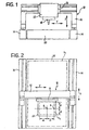
- Figure 1 is an end elevational view and Figure 2 is a plan view of a machine tool operating according to Cartesian coordinates of a generally known type, which has a manipulator device according to the invention associated thereto, as will be described below.
- the carriage 12 supports in its turn a slide 16 which is adapted to move in an orthogonal linear direction Y.
- a tool 18 which in the above-mentioned examples may be a drawing pen, a laser source or a milling cutter, is directly supported by the slide.
- the tool 18 may also be connected to the slide 16 in such a manner that it can be moved in a linear direction Z orthogonal to the said two linear directions X and Y.
- a worktable is interposed between the slideways 14 and is adapted to support a workpiece, such as a metal sheet, to be machined by means of the tool 18.
- travelling members such as the carriage 12 and the slide 16 of the travelling assembly 10 of Figures 1 and 2, will be equipped with respective numerically controlled actuators, not shown.
- the cutting path should have to be followed ideally at a constant tangential speed equal to the maximum macining speed allowed by the power of the laser, by the type and the thickness of the material, and by other well known factors related to this cutting technology.
- the object of the invention is to provide a machine tool which, although including heavy elements, such as the carriage 12 and the slide 16, in order to accomplish large movements, is able to quickly perform, in the whole area or volume of the machine, precision operations, such as plotting, cutting, drilling or shaping operations, even on workpieces of large dimensions.
- the first assembly 10 carries in its turn a second assembly, indicated 22 in Figures 1 and 2, four preferred embodiments of which will be described below.
- the second assembly 22 which includes a tool, is fixed to the slide 16 of the first assembly 10 and a moves with it in the direction conventionally indicated Y, as well as with the carriage 1, in the direction conventionally indicated X.
- the second assembly 22 will also be called below "light assembly”.
- the invention is based on the remark that only a light assembly and therefore with limited strokes can develop very high dynamic performances. In order to extend the benefits of these performances to spaces much wider than those of the light assembly it is necessary for it to be continuously displaced along the cutting path (or other working path) by a conventional heavy assembly having two or three axes, such as that indicated 10 in Figures 1 and 2.
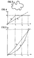
- the tool 18 is at point A, in the centre of the square S 2 .
- the half-side d is equal to the minimum distance between the centre A and the periphery of the narrow space S 2 , the most critical case is that of the movement of the light assembly 22 from A to B, considering that the tool 18, and therefore the assembly 22, will then have to go on further, in the space S 1 , in order to perform a rectilinear cut beyond the point B in the direction A-B.
- the movements of the two assemblies 10 and 22 start at the same time.
- the light assembly 22 starts with the highest possible acceleration (line v 2 , Figure 4) in order to reach as soon as possible the maximum cutting speed v t , which is reached at time t 1 , after which it goes on maintaining its speed constant.
- the carriage 16 which displaces the narrow space S 2 , begins to move with an acceleration which is substantially lower than the previous one and is consistent with the characteristics of the first assembly 10.
- the maximum speed the first assembly 10 can reach be substantially higher than the maximum cutting speed v t .
- the speed of movement v 1 of the heavy assembly 10 will reach, at the time t 2 , the cutting speed of the tool 18 and will exceed it, recovering the previously accrued delay to bring back the position of the tool 18 to the centre of the narrow space S 2 .
- the machine of the invention is provided with a manipulator device for the tool that is particularly effective, can be used independently on relatively small workpieces and can be mounted as well as a second assembly on a machine tool as claimed, in order to operate on relatively large workpieces.
- Manipulator devices particularly adapted to comply with the above definition are known in various forms and an example of them is disclosed by the document US-A-5 656 905.
- the devices in question are the so-called “concurrent axes devices” or “space robots” or “PKMs” ("Parallel Kinematic Machines").
- the means which control the movements and support the platform comprise numerically controlled actuators which are connected to the platform by linkages adapted to vary the distance between the ends of the linkages.
- the known PKM devices have however the drawback to be remarkably bulky in comparison with the space of movement of the travelling platform, because of the shapes of the said linkages, as well as the drawback of requiring a complicated algorithm for controlling the movements of the platform, which in its turn requires a complex software.
- the space of evolution of the travelling platform turns out to be of a complex shape, so that it cannot be fully exploited both for practical (topological) reasons and for the fact that substantial portions of this space can be reached only by passing through singular points of the linkage, which are insurmountable.
- the machine of the present invention is therefore provided with a manipulator device of the concurrent axes type, which on the one hand is much less bulky than the known devices and allows to fully exploit the available space of movement without having singular points, and which, on the other hand, requires a very simple software for controlling the movements of the platform.
- the movements imparted to the platform are linear and directed only according to Cartesian axes.
- These movements are obtainable from actuators preferably constituted by numerically controlled electric motors which, as in the known PKMs, can be advantageously installed on the fixed structure constituted by the frame of the device.
- the actuators can be all identical.
- the actuators of the horizontal axes can be identical to each other, while the third actuator may differ only for the power developed and/or the presence of counterweights.
- the actuators thanks to the fact that they produce linear movements, can be controlled by a software much simpler than those of the known prior art, because of the simplicity of the algorithm which can be used, because it has only to manage Cartesian coordinates.
- the manipulator device of the machine according to the invention can be contained in a volume which is much more reduced with respect to the volume which is required by the linkages of the known PKM technique, for the same volume of the space available for the movements of the platform, such space being likely to be fully exploited thanks to the absence of singular points.
- the manipulator device can be advantageously applied as a travelling second assembly of high dynamics on a travelling member of a machine tool with Cartesian or polar coordinates, or variously articulated as in a robot.
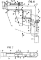
- the tool 18 is carried by a support platform constituted by a block 24 having a square shape in plan view.
- the platform 24 is supported by a frame generally indicated 26.
- the frame 26 is constituted by a rigid member having two branches 28, 30 extending according to two orthogonal directions X, Y in a working plan which is parallel to these directions.
- Each branch 28, 30 is equipped with a respective slideway 32, 34.
- slideways 32, 34 are staggered in the direction Z perpendicular to the sliding plan.
- Each slideway 32, 34 has a respective structure 36, 38 associated thereto, which is adapted to travel in the manner of a slide.
- the two sliding structures 36, 38 are constituted by respective beams which are staggered like the slideways 32, 34 in order not to interfere with each other in their movements. This is the reason for which the guides 32, 34 are staggered.
- the two beams 36 and 38 extend in cantilever fashion from the respective branches 28, 30.
- Each sliding structure or beam 36, 38 is equipped with sliding shoes 40, 42, respectively, which are coupled with the respective slideways 32, 34.
- each of the sliding structures or beams 36, 38 is equipped with a slideway 44, 46, respectively, on a side thereof which faces the branch 30, 28, respectively, of the frame 26 to which the other sliding structure or beam is associated.
- the platform 24 is provided, on two sides orthogonal to each other, with sliding shoes 48, 50 which are coupled with the respective slideways 44, 46.
- the configuration of all the slideways 32, 34, 44, 46, on the one hand, and of all the shoes 40, 42, 44, 46, on the other hand is such as to provide a form fit between the slideways and the shoes so that the platform 24 is supported, in addition to be guided, by the frame 26.
- the movements in the direction X of the beam 36 and, consequently, of the platform 24 are imparted by a numerically controlled actuator which, in the example shown, is constituted by an electric motor 52.
- the motor 52 drives a lead screw 54 which is rotatably mounted on two fixed supports 55 and drives in the direction X a nut screw 56 which has a bracket 58 fixed thereto, the bracket being fixed in its turn to the sliding structure or beam 36.
- a numerically controlled actuator which, in the case shown, is also an electric motor 60, identical to the motor 52 and which, through a lead screw 62 which is rotatably mounted on two fixed supports 63, drives in the direction Y a nut screw 64 which has a bracket 66 fixed thereto, the bracket being fixed in its turn to the sliding structure or beam 38.
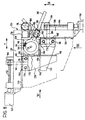
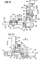
- the tool which in this case may be a cutter for shaping a three-dimensional workpiece, is indicated 118 and its platform is indicated 124.
- the two directions of the platform 124 in the working plane are still indicated X and Y, while the third direction, orthogonal to the preceding ones, is indicated Z.
- the platform 124 is also adapted to move in the direction Z perpendicular to the plane of movement parallel to the directions X and Y, while the motor 176, which is the actuator for the movement according to Z, is still kept on a fixed part, it being secured to the frame 126, as was already done with the actuators for the movements according to X and Y.
- Each carriage 168, 170 bears a pair of guide columns 172, 174 (or equivalent members) which extend in the perpendicular direction Z.
- This solution which can be better understood from Figures 8 to 10, can be obtained by any type of prismatic sliding in the direction Z.
- Each of the pairs of guide columns 172, 174 is in engagement with the respective beam 136, 138, which therefore can also translate according to Z while remaining parallel to itself.
- the two beams 136, 138 are staggered in the direction perpendicular to Z.
- the platform 124 has displacing means associated thereto for displacing in unison in the direction Z both the platform itself and the two beams 136, 138 which, in that direction, are bound to the platform by the shoes 148, 150 and the respective slideways 144, 146, irrespective of the position of the platform 124 in the plane of movement according to X, Y.
- the displacement means in the direction Z comprise a numerically controlled actuator, preferably an electric motor 176, whose body is fixed, as already said before, because it is fastened to the frame 126 by a post 178.
- a numerically controlled actuator preferably an electric motor 176, whose body is fixed, as already said before, because it is fastened to the frame 126 by a post 178.
- the shaft of the motor 176 through a lead screw 180 rotatably mounted on fixed supports 181, moves a nut screw 182 according to Z.
- the nut screw 182 is fastened to a driving member 184 in the form of a slide which is adapted to move in the direction Z along slideways 186.
- the slide or driving member 184 has, through a radial-axial bearing 188, a head 190 associated thereto, which is adapted to revolve in a plane parallel to the plane of movement according to X, Y, as well as adapted to be moved by the motor 176 in the direction Z.
- the head 190 is shaped like a guide bushing having an axis parallel to the plane of movement according to X, Y.
- a rod 192 is slidably mounted in the head or bushing 190.
- the rod 192 at one of its ends which is contiguous to the platform 124, has a ring-like frame 194 which is parallel to the platform 124.
- a hub 196 which is contained in the ring-like frame 194, is fastened to the platform 124.
- An axial-radial bearing 198 is interposed between the hub 196 and the frame 194 a 198.
- the movements imparted by the motor or actuator 176 in the direction Z are transmitted to the platform 124 and, through the latter, to the two beams 136, 138, irrespective of the position taken by the platform 124 within the frame 126.
- This is obtained thanks to the fact that the rod 192 can slide in the head or bushing 190 as well as to the fact that the head 190 and the rod 192 can revolve around an axis which is parallel to the direction Z.
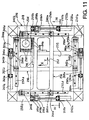
- the tool 218 is carried by a support platform constituted by a block 224 having a square shape in plan view.
- the platform 224 is supported by a frame generally indicated 226.
- the frame 226 is constituted by a rigid member in the form of a square or rectangular frame with branches 228a, 228b and 230a, 230b, respectively, facing each other by pairs.
- the branches 228a, 228b extend according to a direction X and the branches 230a, 230b extend according to an orthogonal direction Y, the two directions X, Y still defining a working plane.
- Each branch 228a, 228b and 230a, 230b is equipped with a slideway 232a, 232b and 234a, 234b, respectively.
- the slideways 232a, 232b, on the one hand, and the slideways 234a, 234b, on the other hand, are parallel to each other.
- the slideways 232a, 232b, on the one hand, and the slideways 234a, 234b, on the other hand, are staggered in the direction Z perpendicular to the sliding plane.
- Each slideway 232a, 232b and 234a, 234b has a structure 236 and 238, respectively, associated thereto, which is adapted to travel in the manner of a slide.
- the sliding structures 236, 238 are constituted by orthogonal beams extending, in the manner of bridges, between two opposite branches 228a, 228b and 230a, 230b, respectively, of the frame 226 and are guided along both of these branches.
- the two beams 236, 238 have rectangular lightening windows, 237 and 239, respectively, to reduce their weight and therefore their inertial mass.
- the two sliding structures or beams 236, 238 are staggered like the slideways 232a, 232b and 234a, 234b in order not to interfere with each other in their movements.
- Each of the sliding structures or beams 236, 238 is equipped with sliding shoes 240a, 240b and 242a, 242b, respectively, which are coupled with the respective slideways 232a, 232b and 234a, 234b.
- each of the sliding structures or beams 236, 238 is equipped with a slideway 244, 246, respectively.
- the platform 224 is provided, on two sides orthogonal to each other, with sliding shoes 248, 250 which are coupled with the respective slideways 244, 246.
- the configuration of all the slideways 232, 234, 244, 246, on the one hand, and of all the shoes 240, 242, 244, 246, on the other hand, is such as to provide a form fit, more particularly a dovetail fit, between the slideways and the shoes, so that the platform 224 is both supported and guided by the frame 226.
- the movements in the direction X of the beam 236 and, consequently, of the platform 224 are produced by a pair of numerically controlled actuators working in parallel which, in the example shown, are still constituted by two electric motors 252a, 252b.
- the two motors 252a, 252b drive in unison each a respective lead screw 254a, 254b which is rotatably mounted on two fixed supports 255a, 255b.
- the lead screws 254a, 254b drive in the direction X respective nut screws 256a, 256b which are fixed in brackets constituted by respective side appendages 258a, 258b of the sliding structure or beam 236.
- the motors 260a, 260b drive in unison each a respective lead screw 262a, 262b which is rotatably mounted on two fixed supports 263a, 263b.
- the lead screws 262a, 262b drive in the direction Y respective nut screws 264a, 264b which are fixed in brackets constituted by respective side appendages 266a, 266b of the sliding structure or beam 238.
- the manipulator device shown in Figures 11 and 12 has, with respect to the one shown in Figures 6 and 7, the advantage that much more accurate movements can be imparted to the tool 218 for the fact that each of the two beams 236, 238 is guided by parallel slideways at both ends and, in addition, is driven, at each end, by driving means operating synchronously in parallel.
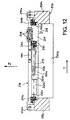
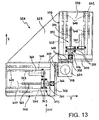
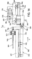
- the tool 318 is still carried by a support platform constituted by a block 324 having a square shape in plan view.
- the platform 324 is supported by a frame generally indicated 326.
- the frame 326 is constituted by a rigid member which includes two rectangular tables 328, 330 which are rigidly interconnected by a gusset or brace 329.
- the major axes of the tables 328, 330 extend according to two orthogonal directions X, Y, respectively, in a working plane which is parallel to these directions.
- Each table 328, 330 is equipped, on its underside, with respective pairs of parallel slideways 332, 334.
- pairs of slideways 332, 334 are staggered in the direction Z perpendicular to the sliding plane.
- Each pair of slideways 332, 334 has a respective structure 336, 338 associated thereto, which is adapted to travel in the manner of a slide.
- the two sliding structures 336, 338 comprise respective plates which are staggered like the slideways 332, 334 in order not to interfere with each other in their movements.
- Each of the two sliding plates 336 and 338 extends under a respective table 328, 330 and is parallel to the latter.
- Each sliding plate 336, 338 is equipped, on its upper face, with sliding shoes 340, 342, respectively, which are coupled with the respective pairs of slideways 332, 334.
- each of the sliding plates 336, 338 is equipped with a slideway 344, 346, respectively, on a side thereof which faces the table 330, 328.
- the platform 324 is provided, on two sides orthogonal to each other, with sliding shoes 348, 350 which are coupled with the respective slideways 344, 346.
- the configuration of all the slideways 332, 334, 344, 346, on the one hand, and of all the shoes 340, 342, 344, 346, on the other hand, is such as to provide a form fit, more particularly a dovetail fit, between the slideways and the shoes so that the platform 324 is supported, in addition to be guided, by the frame 326.
- the drive unit 351 includes a numerically controlled actuator which, in the example shown, is still constituted by an electric motor 352.
- the motor 352 drives a lead screw 354 which is rotatably mounted on two fixed supports 355, carried by the top of the table 328.
- the lead screw 354 drives in the direction X a nut screw 356 which has a bracket 358 fixed thereto, the bracket being 358 fixed in its turn to the sliding plate 336 which underlies the table 328.
- the drive unit includes a numerically controlled actuator which, in the case shown, is still an electric motor 360, identical to the motor 352.
- the motor 360 drives a lead screw 362 which is rotatably mounted on two fixed supports 363, carried by the top of the table 330.
- the lead screw 362 drives in the direction Y a nut screw 364 which has a bracket 366 fixed thereto, the bracket being fixed in its turn to the sliding plate 338.
- a manipulator as shown in Figures 13 ad 14 is likely to be even more accurate, as regards the movements of the tool 318, because the sliding structures 336, 338 are not beams subject to flexure, such as the cantilever beams 36, 38 of Figures 6 and 7 and the beams or girders 236, 238 supported at both ends of Figures 11 and 12.
- the manipulator of Figures 13 and 14 Due to the arrangement of the whole driving units 351, 359 on the top of the tables 328, 330, the manipulator of Figures 13 and 14 has the further advantage that the space under the manipulator, in which the tool 318 moves, is completely free from obstacles an can be fully exploited for the machining or cutting operations etc.
Landscapes
- Engineering & Computer Science (AREA)
- Mechanical Engineering (AREA)
- General Health & Medical Sciences (AREA)
- Orthopedic Medicine & Surgery (AREA)
- Physics & Mathematics (AREA)
- General Physics & Mathematics (AREA)
- Automation & Control Theory (AREA)
- Health & Medical Sciences (AREA)
- Human Computer Interaction (AREA)
- Manufacturing & Machinery (AREA)
- Robotics (AREA)
- Manipulator (AREA)
- Machine Tool Units (AREA)
- Automobile Manufacture Line, Endless Track Vehicle, Trailer (AREA)
- Feeding Of Workpieces (AREA)
- Automatic Control Of Machine Tools (AREA)
Applications Claiming Priority (3)
| Application Number | Priority Date | Filing Date | Title |
|---|---|---|---|
| ITTO20000657 | 2000-06-30 | ||
| IT2000TO000657A IT1320478B1 (it) | 2000-06-30 | 2000-06-30 | Macchina operatrice e dispositivo manipolatore installabile su talemacchina. |
| EP01956494A EP1294544B1 (de) | 2000-06-30 | 2001-06-23 | Werkzeugmaschine und manipulatoranordnung, die auf einer solchen maschine montiert ist |
Related Parent Applications (1)
| Application Number | Title | Priority Date | Filing Date |
|---|---|---|---|
| EP01956494A Division EP1294544B1 (de) | 2000-06-30 | 2001-06-23 | Werkzeugmaschine und manipulatoranordnung, die auf einer solchen maschine montiert ist |
Publications (2)
| Publication Number | Publication Date |
|---|---|
| EP1557244A2 true EP1557244A2 (de) | 2005-07-27 |
| EP1557244A3 EP1557244A3 (de) | 2005-11-30 |
Family
ID=11457882
Family Applications (2)
| Application Number | Title | Priority Date | Filing Date |
|---|---|---|---|
| EP05006505A Ceased EP1557244A3 (de) | 2000-06-30 | 2001-06-23 | Werkzeugmaschine mit Handhabungsgerät |
| EP01956494A Expired - Lifetime EP1294544B1 (de) | 2000-06-30 | 2001-06-23 | Werkzeugmaschine und manipulatoranordnung, die auf einer solchen maschine montiert ist |
Family Applications After (1)
| Application Number | Title | Priority Date | Filing Date |
|---|---|---|---|
| EP01956494A Expired - Lifetime EP1294544B1 (de) | 2000-06-30 | 2001-06-23 | Werkzeugmaschine und manipulatoranordnung, die auf einer solchen maschine montiert ist |
Country Status (8)
| Country | Link |
|---|---|
| US (1) | US7886629B2 (de) |
| EP (2) | EP1557244A3 (de) |
| JP (1) | JP4902086B2 (de) |
| AT (1) | ATE302669T1 (de) |
| DE (1) | DE60112937T2 (de) |
| ES (1) | ES2248367T3 (de) |
| IT (1) | IT1320478B1 (de) |
| WO (1) | WO2002002281A1 (de) |
Cited By (2)
| Publication number | Priority date | Publication date | Assignee | Title |
|---|---|---|---|---|
| EP2008752A1 (de) * | 2007-06-30 | 2008-12-31 | Trumpf Werkzeugmaschinen GmbH + Co. KG | Maschine zum Bearbeiten von Werkstücken und Verfahren zum maschinellen Bearbeiten von Werkstücken |
| US7767932B2 (en) | 2007-06-29 | 2010-08-03 | Trumpf, Inc. | High dynamics laser processing machine |
Families Citing this family (25)
| Publication number | Priority date | Publication date | Assignee | Title |
|---|---|---|---|---|
| DE10333456A1 (de) | 2003-07-22 | 2005-02-24 | Kuka Schweissanlagen Gmbh | Verfahren und Vorrichtung zum Laserbearbeiten von Werkstücken |
| ITTO20040647A1 (it) * | 2004-09-28 | 2004-12-28 | Prima Ind Spa | Punzonatrice laser |
| ITTO20050016A1 (it) * | 2005-01-13 | 2006-07-14 | Prima Ind Spa | Macchina operatrice laser |
| ES2317178T3 (es) * | 2005-05-18 | 2009-04-16 | Franco Sartorio | Dispositivo de equilibrado para una maquina herramienta. |
| ITTO20050578A1 (it) * | 2005-08-16 | 2007-02-17 | Prima Ind Spa | Procedimento di gestione di sistemi dotati di attuatori ridondanti |
| JP4926758B2 (ja) * | 2007-02-27 | 2012-05-09 | 株式会社ハーモニック・ドライブ・システムズ | 粗微動機構 |
| US20080295746A1 (en) * | 2007-05-30 | 2008-12-04 | Chien-Cheng Lin | Linear Table with an Adjustable Dust-proof Structure |
| DE102007026356A1 (de) | 2007-06-06 | 2009-01-08 | Trumpf Werkzeugmaschinen Gmbh + Co. Kg | Mess- oder Werkzeugmaschine mit redundanten translatorisch wirksamen Achsen zur kontinuierlichen Bewegung an komplexen Bahnkurven |
| DE102007027503A1 (de) | 2007-06-14 | 2009-01-08 | Trumpf Werkzeugmaschinen Gmbh + Co. Kg | Verfahren zur optimierten Bewegungskoordination von Mess- oder Werkzeugmaschinen mit redundanten translatorisch wirksamen Achsen |
| DE102007028934A1 (de) * | 2007-06-22 | 2008-12-24 | Trumpf Werkzeugmaschinen Gmbh + Co. Kg | Verfahren zur optimierten Bewegungskoordination von Mess-oder Werkzeugmaschinen mit redundanten translatorisch wirksamen Achsen |
| DE102007034885A1 (de) | 2007-07-14 | 2009-01-15 | Trumpf Werkzeugmaschinen Gmbh + Co. Kg | Einrichtung oder Verfahren einer Steuerung für Mess- und Werkzeugmaschinen mit redundanten translatorisch wirkenden Achsen |
| DE102007040022A1 (de) | 2007-08-24 | 2009-02-26 | Trumpf Werkzeugmaschinen Gmbh + Co. Kg | Verfahren zur optimierten Bewegungskoordination von Mess- oder Werkzeugmaschinen mit redundanten translatorisch wirksamen Achsen |
| CA2604860A1 (en) * | 2007-10-01 | 2009-04-01 | Prism Medical Ltd. | Track for patient lift devices |
| US8458871B2 (en) * | 2008-06-26 | 2013-06-11 | Hg-Farley Laserlab Co. Pty Ltd | Secondary positioning device for workpiece machining |
| IT1394985B1 (it) | 2009-07-27 | 2012-08-07 | Salvagnini Italia Spa | Manipolatore a bassa inerzia per macchina per taglio laser di lamiere metalliche piane. |
| DE102010050149A1 (de) * | 2010-11-03 | 2012-05-03 | Mubea Systems, S.A. | Vorrichtung zum Bearbeiten eines großformatigen Werkstücks |
| DE102011119211A1 (de) | 2011-11-23 | 2013-05-23 | Andreas Ehlerding | Bewegungseinrichtung mit kombiniert rotorischer und translatorischer Bewegung einer redundant wirksamen Zusatzachseneinheit als Teil einer Werkzeugmaschine |
| DE102011120318A1 (de) | 2011-12-06 | 2013-06-06 | Andreas Ehlerding | Bewegungseinrichtung zur kombiniert translatorischen und rotorischen Bewegung mit redundant wirksamer Zusatzachseneinheit, als Teil einer Werkzeugmaschine |
| DE102011122202A1 (de) | 2011-12-23 | 2013-06-27 | Andreas Ehlerding | Bewegungseinrichtung mit translatorischer Bewegung eines längenveränderlichen Auslegers, der eine hierzu redundant wirksame Zusatzachseneinheit trägt |
| EP2692481A1 (de) | 2012-08-03 | 2014-02-05 | Bystronic Laser AG | Strahlbearbeitungsvorrichtung |
| US9205600B1 (en) * | 2014-03-04 | 2015-12-08 | New Matter, Inc. | Moveable platform with 2-axis rack and pinion drive |
| WO2015181772A1 (en) | 2014-05-30 | 2015-12-03 | Prima Industrie S.P.A. | Laser operating machine for additive manufacturing by laser sintering and corresponding method |
| JP6847865B2 (ja) | 2015-06-22 | 2021-03-24 | エレクトロ サイエンティフィック インダストリーズ インコーポレーテッド | 多軸工作機械及びこれを制御する方法 |
| EP3272455B1 (de) * | 2016-07-20 | 2021-05-26 | AFW Holding GmbH | Bearbeitungseinheit zur spanenden bearbeitung von werkstücken |
| EP3793768B1 (de) * | 2018-05-15 | 2024-01-03 | Universität Stuttgart | Vorrichtung und verfahren zur erzeugung einer relativbewegung zwischen einem werkzeug und einem werkstück |
Citations (3)
| Publication number | Priority date | Publication date | Assignee | Title |
|---|---|---|---|---|
| EP0448107A1 (de) * | 1990-03-22 | 1991-09-25 | Toyoda Koki Kabushiki Kaisha | Verfahren und Vorrichtung zum Bearbeiten von unrunden Werkstücken |
| US5309847A (en) * | 1990-04-27 | 1994-05-10 | Ntn Corporation | Adjustably movable work table |
| WO1996029634A1 (en) * | 1995-03-20 | 1996-09-26 | Electro Scientific Industries, Inc. | Multi-rate positioner system having an improved profiling filter |
Family Cites Families (16)
| Publication number | Priority date | Publication date | Assignee | Title |
|---|---|---|---|---|
| US3638933A (en) * | 1970-08-10 | 1972-02-01 | Yosemite Lab | Precision x-y positioning table |
| JPS55134414A (en) * | 1979-04-06 | 1980-10-20 | Hitachi Ltd | Precise moving unit |
| JPS60232839A (ja) * | 1984-05-04 | 1985-11-19 | Hitachi Ltd | 直線状案内軌道の固定装置 |
| JPS61145938A (ja) * | 1984-12-19 | 1986-07-03 | Fujitsu Ltd | 回線割当制御方式 |
| JPS63191533A (ja) * | 1987-01-30 | 1988-08-09 | Kokuyou Denki Kogyo Kk | 2次元位置決め駆動装置 |
| JPH0811337B2 (ja) * | 1990-01-12 | 1996-02-07 | 健 柳沢 | 多重型2次元運動機構 |
| US5311791A (en) * | 1991-08-07 | 1994-05-17 | Ken Yanagisawa | Two dimensional drive system |
| US5390128A (en) * | 1993-04-12 | 1995-02-14 | Cargill Detroit Corporation | Robotic processing and inspection system |
| JP3459315B2 (ja) * | 1994-07-11 | 2003-10-20 | 日本トムソン株式会社 | ボールねじを具備した駆動装置及び該駆動装置を含むxy駆動装置 |
| US6134981A (en) * | 1999-12-03 | 2000-10-24 | Nikon Research Corporation Of America | Precision scanning apparatus and method with fixed and movable guide members |
| US5656905A (en) * | 1995-04-03 | 1997-08-12 | Tsai; Lung-Wen | Multi-degree-of-freedom mechanisms for machine tools and the like |
| US5724893A (en) * | 1996-10-15 | 1998-03-10 | Taichung Machinery Works Co. Ltd. | Servo-type shaking table assembly |
| US5971254A (en) * | 1997-01-02 | 1999-10-26 | Texas Instruments Incorporated | Decoupled xyz stage |
| JPH11138371A (ja) * | 1997-10-31 | 1999-05-25 | Yaskawa Electric Corp | X−yテーブル |
| JP2000230991A (ja) * | 1999-02-12 | 2000-08-22 | Takeshi Yanagisawa | 2次元運動機構 |
| DE19932645C5 (de) * | 1999-07-13 | 2007-01-11 | Agie S.A., Losone | Funkenerosionsmaschine und Modulsatz für den Zusammenbau von Werkzeugmaschinen, insbesondere Funkenerosionsmaschinen |
-
2000
- 2000-06-30 IT IT2000TO000657A patent/IT1320478B1/it active
-
2001
- 2001-06-23 EP EP05006505A patent/EP1557244A3/de not_active Ceased
- 2001-06-23 DE DE60112937T patent/DE60112937T2/de not_active Expired - Lifetime
- 2001-06-23 AT AT01956494T patent/ATE302669T1/de not_active IP Right Cessation
- 2001-06-23 US US10/332,262 patent/US7886629B2/en active Active
- 2001-06-23 EP EP01956494A patent/EP1294544B1/de not_active Expired - Lifetime
- 2001-06-23 JP JP2002506897A patent/JP4902086B2/ja not_active Expired - Lifetime
- 2001-06-23 WO PCT/EP2001/007045 patent/WO2002002281A1/en active IP Right Grant
- 2001-06-23 ES ES01956494T patent/ES2248367T3/es not_active Expired - Lifetime
Patent Citations (3)
| Publication number | Priority date | Publication date | Assignee | Title |
|---|---|---|---|---|
| EP0448107A1 (de) * | 1990-03-22 | 1991-09-25 | Toyoda Koki Kabushiki Kaisha | Verfahren und Vorrichtung zum Bearbeiten von unrunden Werkstücken |
| US5309847A (en) * | 1990-04-27 | 1994-05-10 | Ntn Corporation | Adjustably movable work table |
| WO1996029634A1 (en) * | 1995-03-20 | 1996-09-26 | Electro Scientific Industries, Inc. | Multi-rate positioner system having an improved profiling filter |
Cited By (4)
| Publication number | Priority date | Publication date | Assignee | Title |
|---|---|---|---|---|
| US7767932B2 (en) | 2007-06-29 | 2010-08-03 | Trumpf, Inc. | High dynamics laser processing machine |
| EP2008752A1 (de) * | 2007-06-30 | 2008-12-31 | Trumpf Werkzeugmaschinen GmbH + Co. KG | Maschine zum Bearbeiten von Werkstücken und Verfahren zum maschinellen Bearbeiten von Werkstücken |
| US8294061B2 (en) | 2007-06-30 | 2012-10-23 | Trumpf Werkzeugmaschinen Gmbh + Co. Kg | Machine for machining workpieces and a method of machining workpieces |
| US8909367B2 (en) | 2007-06-30 | 2014-12-09 | Trumpf Werkzeugmaschinen Gmbh + Co. Kg | Machine for machining workpieces and a method of machining workpieces |
Also Published As
| Publication number | Publication date |
|---|---|
| ITTO20000657A0 (it) | 2000-06-30 |
| DE60112937D1 (de) | 2005-09-29 |
| EP1294544A1 (de) | 2003-03-26 |
| EP1294544B1 (de) | 2005-08-24 |
| EP1557244A3 (de) | 2005-11-30 |
| JP2004501790A (ja) | 2004-01-22 |
| JP4902086B2 (ja) | 2012-03-21 |
| ES2248367T3 (es) | 2006-03-16 |
| ITTO20000657A1 (it) | 2001-12-30 |
| IT1320478B1 (it) | 2003-11-26 |
| US7886629B2 (en) | 2011-02-15 |
| ATE302669T1 (de) | 2005-09-15 |
| WO2002002281A1 (en) | 2002-01-10 |
| DE60112937T2 (de) | 2006-06-29 |
| US20040025761A1 (en) | 2004-02-12 |
Similar Documents
| Publication | Publication Date | Title |
|---|---|---|
| EP1294544B1 (de) | Werkzeugmaschine und manipulatoranordnung, die auf einer solchen maschine montiert ist | |
| JP5102632B2 (ja) | レーザ加工機 | |
| JP4763938B2 (ja) | 工作機械 | |
| EP2745959B1 (de) | Werkzeugmaschine mit Drehwerkzeug und Schabschneider | |
| RU2546269C2 (ru) | Низкоинерционный манипулятор для станков для лазерной резки плоского листового металла | |
| US6099217A (en) | Device for spatially moving a body with three to six degrees of freedom in a controlled manner | |
| JP4258790B2 (ja) | 一平面内でプラットホームを移動させる駆動装置 | |
| US6068431A (en) | Machine tool having a gantry and a vertical spindle | |
| EA005147B1 (ru) | Кинематическое устройство для обеспечения опоры и программируемого перемещения терминального элемента в станке или приборе | |
| JP4804473B2 (ja) | レーザ穴開け機 | |
| JPH06155203A (ja) | 多重スピンドル機械加工装置のための位置決め装置及び加工方法 | |
| JP2798530B2 (ja) | レーザ加工機 | |
| TWI477350B (zh) | 進給裝置及應用該進給裝置之機床 | |
| JP2000079527A5 (de) | ||
| US6835912B2 (en) | Laser cutting machine with two Y-axis drives | |
| GB2082484A (en) | Machine with horizontally sliding tool head carriage | |
| JP2003145374A (ja) | 工作機械 | |
| CN109227318A (zh) | 双工位数控机床 | |
| JP3126216B2 (ja) | レーザ加工機 | |
| KR20130043724A (ko) | 레이저 가공장치 | |
| US20050103764A1 (en) | Laser cutting machine with two X-axis drives | |
| KR20130043715A (ko) | 발진기 이동형 레이저 가공장치 | |
| RU2290283C1 (ru) | Многооперационный металлообрабатывающий станок | |
| JPH0347974B2 (de) | ||
| CN113843529A (zh) | 一种汽车设备加工用激光切割机 |
Legal Events
| Date | Code | Title | Description |
|---|---|---|---|
| PUAI | Public reference made under article 153(3) epc to a published international application that has entered the european phase |
Free format text: ORIGINAL CODE: 0009012 |
|
| AC | Divisional application: reference to earlier application |
Ref document number: 1294544 Country of ref document: EP Kind code of ref document: P |
|
| AK | Designated contracting states |
Kind code of ref document: A2 Designated state(s): AT BE CH CY DE DK ES FI FR GB GR IE IT LI LU MC NL PT SE TR |
|
| PUAL | Search report despatched |
Free format text: ORIGINAL CODE: 0009013 |
|
| AK | Designated contracting states |
Kind code of ref document: A3 Designated state(s): AT BE CH CY DE DK ES FI FR GB GR IE IT LI LU MC NL PT SE TR |
|
| 17P | Request for examination filed |
Effective date: 20060524 |
|
| AKX | Designation fees paid |
Designated state(s): AT BE CH CY DE LI |
|
| RBV | Designated contracting states (corrected) |
Designated state(s): DE ES FR GB IT |
|
| 17Q | First examination report despatched |
Effective date: 20060901 |
|
| STAA | Information on the status of an ep patent application or granted ep patent |
Free format text: STATUS: THE APPLICATION HAS BEEN REFUSED |
|
| 18R | Application refused |
Effective date: 20080204 |