EP1556619B1 - Spülvorrichtung für einen kreislauf mit mindestens einem hydraulischen motor - Google Patents
Spülvorrichtung für einen kreislauf mit mindestens einem hydraulischen motor Download PDFInfo
- Publication number
- EP1556619B1 EP1556619B1 EP03778478A EP03778478A EP1556619B1 EP 1556619 B1 EP1556619 B1 EP 1556619B1 EP 03778478 A EP03778478 A EP 03778478A EP 03778478 A EP03778478 A EP 03778478A EP 1556619 B1 EP1556619 B1 EP 1556619B1
- Authority
- EP
- European Patent Office
- Prior art keywords
- valve
- pressure
- circuit according
- control
- exchange
- Prior art date
- Legal status (The legal status is an assumption and is not a legal conclusion. Google has not performed a legal analysis and makes no representation as to the accuracy of the status listed.)
- Expired - Fee Related
Links
Images


Classifications
-
- F—MECHANICAL ENGINEERING; LIGHTING; HEATING; WEAPONS; BLASTING
- F16—ENGINEERING ELEMENTS AND UNITS; GENERAL MEASURES FOR PRODUCING AND MAINTAINING EFFECTIVE FUNCTIONING OF MACHINES OR INSTALLATIONS; THERMAL INSULATION IN GENERAL
- F16K—VALVES; TAPS; COCKS; ACTUATING-FLOATS; DEVICES FOR VENTING OR AERATING
- F16K17/00—Safety valves; Equalising valves, e.g. pressure relief valves
- F16K17/003—Safety valves; Equalising valves, e.g. pressure relief valves reacting to pressure and temperature
-
- F—MECHANICAL ENGINEERING; LIGHTING; HEATING; WEAPONS; BLASTING
- F15—FLUID-PRESSURE ACTUATORS; HYDRAULICS OR PNEUMATICS IN GENERAL
- F15B—SYSTEMS ACTING BY MEANS OF FLUIDS IN GENERAL; FLUID-PRESSURE ACTUATORS, e.g. SERVOMOTORS; DETAILS OF FLUID-PRESSURE SYSTEMS, NOT OTHERWISE PROVIDED FOR
- F15B21/00—Common features of fluid actuator systems; Fluid-pressure actuator systems or details thereof, not covered by any other group of this subclass
- F15B21/005—Filling or draining of fluid systems
-
- F—MECHANICAL ENGINEERING; LIGHTING; HEATING; WEAPONS; BLASTING
- F15—FLUID-PRESSURE ACTUATORS; HYDRAULICS OR PNEUMATICS IN GENERAL
- F15B—SYSTEMS ACTING BY MEANS OF FLUIDS IN GENERAL; FLUID-PRESSURE ACTUATORS, e.g. SERVOMOTORS; DETAILS OF FLUID-PRESSURE SYSTEMS, NOT OTHERWISE PROVIDED FOR
- F15B21/00—Common features of fluid actuator systems; Fluid-pressure actuator systems or details thereof, not covered by any other group of this subclass
- F15B21/04—Special measures taken in connection with the properties of the fluid
- F15B21/042—Controlling the temperature of the fluid
- F15B21/0423—Cooling
-
- F—MECHANICAL ENGINEERING; LIGHTING; HEATING; WEAPONS; BLASTING
- F16—ENGINEERING ELEMENTS AND UNITS; GENERAL MEASURES FOR PRODUCING AND MAINTAINING EFFECTIVE FUNCTIONING OF MACHINES OR INSTALLATIONS; THERMAL INSULATION IN GENERAL
- F16H—GEARING
- F16H61/00—Control functions within control units of change-speed- or reversing-gearings for conveying rotary motion ; Control of exclusively fluid gearing, friction gearing, gearings with endless flexible members or other particular types of gearing
- F16H61/38—Control of exclusively fluid gearing
- F16H61/40—Control of exclusively fluid gearing hydrostatic
- F16H61/4078—Fluid exchange between hydrostatic circuits and external sources or consumers
- F16H61/4104—Flushing, e.g. by using flushing valves or by connection to exhaust
-
- F—MECHANICAL ENGINEERING; LIGHTING; HEATING; WEAPONS; BLASTING
- F16—ENGINEERING ELEMENTS AND UNITS; GENERAL MEASURES FOR PRODUCING AND MAINTAINING EFFECTIVE FUNCTIONING OF MACHINES OR INSTALLATIONS; THERMAL INSULATION IN GENERAL
- F16K—VALVES; TAPS; COCKS; ACTUATING-FLOATS; DEVICES FOR VENTING OR AERATING
- F16K17/00—Safety valves; Equalising valves, e.g. pressure relief valves
- F16K17/02—Safety valves; Equalising valves, e.g. pressure relief valves opening on surplus pressure on one side; closing on insufficient pressure on one side
- F16K17/04—Safety valves; Equalising valves, e.g. pressure relief valves opening on surplus pressure on one side; closing on insufficient pressure on one side spring-loaded
- F16K17/10—Safety valves; Equalising valves, e.g. pressure relief valves opening on surplus pressure on one side; closing on insufficient pressure on one side spring-loaded with auxiliary valve for fluid operation of the main valve
- F16K17/105—Safety valves; Equalising valves, e.g. pressure relief valves opening on surplus pressure on one side; closing on insufficient pressure on one side spring-loaded with auxiliary valve for fluid operation of the main valve using choking or throttling means to control the fluid operation of the main valve
-
- F—MECHANICAL ENGINEERING; LIGHTING; HEATING; WEAPONS; BLASTING
- F16—ENGINEERING ELEMENTS AND UNITS; GENERAL MEASURES FOR PRODUCING AND MAINTAINING EFFECTIVE FUNCTIONING OF MACHINES OR INSTALLATIONS; THERMAL INSULATION IN GENERAL
- F16K—VALVES; TAPS; COCKS; ACTUATING-FLOATS; DEVICES FOR VENTING OR AERATING
- F16K17/00—Safety valves; Equalising valves, e.g. pressure relief valves
- F16K17/36—Safety valves; Equalising valves, e.g. pressure relief valves actuated in consequence of extraneous circumstances, e.g. shock, change of position
- F16K17/38—Safety valves; Equalising valves, e.g. pressure relief valves actuated in consequence of extraneous circumstances, e.g. shock, change of position of excessive temperature
-
- F—MECHANICAL ENGINEERING; LIGHTING; HEATING; WEAPONS; BLASTING
- F15—FLUID-PRESSURE ACTUATORS; HYDRAULICS OR PNEUMATICS IN GENERAL
- F15B—SYSTEMS ACTING BY MEANS OF FLUIDS IN GENERAL; FLUID-PRESSURE ACTUATORS, e.g. SERVOMOTORS; DETAILS OF FLUID-PRESSURE SYSTEMS, NOT OTHERWISE PROVIDED FOR
- F15B2211/00—Circuits for servomotor systems
- F15B2211/60—Circuit components or control therefor
- F15B2211/61—Secondary circuits
- F15B2211/611—Diverting circuits, e.g. for cooling or filtering
-
- F—MECHANICAL ENGINEERING; LIGHTING; HEATING; WEAPONS; BLASTING
- F15—FLUID-PRESSURE ACTUATORS; HYDRAULICS OR PNEUMATICS IN GENERAL
- F15B—SYSTEMS ACTING BY MEANS OF FLUIDS IN GENERAL; FLUID-PRESSURE ACTUATORS, e.g. SERVOMOTORS; DETAILS OF FLUID-PRESSURE SYSTEMS, NOT OTHERWISE PROVIDED FOR
- F15B2211/00—Circuits for servomotor systems
- F15B2211/60—Circuit components or control therefor
- F15B2211/62—Cooling or heating means
Definitions
- the present invention relates to a circuit comprising an exchange and / or sweeping device and at least one hydraulic motor having a housing which defines an interior space in which the motor cylinder block is arranged, and two main ducts, which are connected to a main pump and which respectively constitute a main supply line and a main exhaust pipe for said hydraulic motor, the exchange device comprising an exchange valve connected to at least one of the mains and able to adopt an open configuration in which it establishes a connection between said main pipe to which it is connected and a tank without pressure, and a closed configuration in which it prevents this connection.
- Such an exchange device has the function of taking fluid on the main druet, to allow the cooling of the fluid before its discharge to a tank without pressure and its feedback into the circuit.
- the sampled fluid passes through the crankcase of the engine and / or the main pump before being discharged to the tank without pressure and reclaimed, usually by an auxiliary pump.
- Known exchange devices comprise a selector which allows the main pipe which is at the lowest pressure to communicate with a valve which allows the evacuation of the fluid only from a pressure threshold. In some devices, the fluid flow taken can be limited.
- document DE-195 22 448 shows an exchange device comprising an exchange selector and a valve arranged one after the other on the exchange circuit.
- US 6,339,928 discloses an exchange device for a closed circuit comprising a selector of the aforementioned type and an exchange valve which is controlled to allow or not the discharge of the fluid under certain operating conditions.
- this exchange valve is controlled according to operating parameters such as the speed of the vehicle driven by the hydraulic motor, the rotational speed of a combustion engine which drives the main pump and the temperature of the fluid in this pump.
- the device exchange valve of US 6,339,928 is entirely electrically controlled by a processor which, from parameters representative of a state of the circuit, determines a control command.
- the device of US 6,339,928 can take this pressure into account only if pressure sensors are arranged in the two main lines or at the outlet of a selector connected to these lines, so that the pressures measured by these sensors are used. by the processor when determining its order.
- the present invention aims to overcome the drawbacks of the state of the art cited above by allowing the exchange of pressure in the pipe to which the exchange valve is connected by a hydraulic control, in addition to the exchange of heat. a parameter other than this pressure.
- the exchange valve comprises a movable member between a first and a second position respectively corresponding to the closed configuration and to the open configuration of the exchange valve.
- the device comprises a control valve which is controlled according to said at least one control parameter to allow the displacement of said movable member
- the device comprises a control valve which is controlled according to said at least one control parameter to allow the displacement of said movable member
- the device comprises an opening control chamber adapted to be connected to the one of the main ducts by a first connecting line for biasing the movable member towards its second position in which said main duct is connected to the unpressurized tank and a closing control chamber able to be connected to a pressure vessel to solicit the movable member to its first position
- the control valve is controlled according to said at least one parameter of comm ande for connecting said closing control chamber to the pressure-free tank or for isolating this chamber from this tank.
- control valve which is controlled by the parameter other than the pressure in the pipe to which the exchange valve is connected, whereas, by the judicious arrangement of the opening control chambers and closing of this exchange valve, the latter is controlled by the pressure in the main pipe to which it is connected.
- the exchange may not be desired under certain particular conditions, for example when starting the hydraulic motor.
- the device comprises a slide switch selector
- the device comprises a slide switch selector
- the drawer can remain momentarily in the position it had before this inversion and thus put the main pipe which was previously at low pressure and which is then at high pressure in communication with the exchange valve, thereby depriving the engine of some of its power.
- the control valve When the value of said at least one control parameter is indicative of the fact that the exchange is not desired, the control valve is controlled to isolate the closure control chamber from the reservoir. Due to this isolation, the pressure in the closing control chamber may be such that the pressure in the opening control chamber, connected to one of the main ducts, is not sufficient to control the opening of the control chamber. exchange valve.
- this parameter other than the fluid pressure in the main pipe is called the first control parameter.
- the pressure in the closing chamber of the exchange valve is such that it prevents leaks between the inlet of the valve. exchange and the tank.
- control valve connects the closing control chamber to the reservoir and the exchange valve. performs the exchange when the pressure in the main pipe to which it is connected allows it.
- the first control parameter representing a state of the circuit is chosen from the pressure of the fluid in an auxiliary line of the circuit (for example the boosting pressure), the temperature of the fluid in a region of the circuit, the speed of the rotor of the motor , accelerating or decelerating said rotor, and the active displacement of the engine.
- the first control parameter can be of any type, since its value is representative of a state of the circuit that conditions the operation of the exchange device.
- the device comprises an actuator able to control the control valve as a function of a threshold of the first control parameter.
- the actuator authorizes the control valve to connect the closing control chamber to the pressure-free tank, allowing then the exchange by the exchange valve hydraulically controlled by the pressure in the main pipe to which it is connected.
- the device comprises an exchange selector adapted to put the main pipe which is at the lowest pressure in communication with the exchange valve.
- This selector therefore allows in a known manner, to connect the exchange valve to the pipe which is at the lowest pressure.
- the invention also applies to an exchange device without such a selector, in particular of the type described in French Patent Application No. 2,819,023.
- the exchange valve may be a non-progressive two-position selector, in which case the fluid flow taken from its open position is limited by a restriction.
- it is a progressive valve such as a valve or pressure limiter that regulates the pressure in the pipe to which it is connected regardless of the flow
- the exchange valve comprises a valve body having an inlet connected to one of the main pipes and an outlet adapted to be connected to the tank without pressure and a movable member between a first and a second position. respectively corresponding to the closed configuration and the open configuration of the exchange valve, said movable member isolating the inlet of the outlet in its first position and connecting the latter in its second position.
- the closing control chamber is associated with resilient exchange return means permanently urging the movable member to its first position.
- the opening control chamber is located at one end of the movable member which is close to the inlet of the valve body, while the closing control chamber is located at the other end of this movable member and communicates with the opening control chamber by a piercing of the movable member.
- the valve body is advantageously arranged in a bore of the housing.
- the exchange valve is advantageously integrated in a cartridge which is directly attached to the engine casing, allowing from a standard motor structure to choose the best-adapted exchange and scanning mode, by modifying only this cartridge.
- the first control parameter can be directly related to a state of the engine, such as its temperature, the fluid temperature which crosses it, its engine capacity, etc.
- the outlet of the exchange valve is connected to the tank without pressure via the interior space of the motor housing.
- the fluid sampled for exchange is used to perform a scan of the interior space of the engine. Indeed, the fluid taken by the exchange valve is injected into the housing, while the fluid in the housing is discharged through the usual leakage return port.
- control valve is a progressive valve.
- the fluid flow rate taken to effect the exchange can thus vary according to the situation of the circuit, in particular as a function of the variation of the first control parameter.
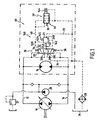
- FIG. 1 shows a closed circuit whose main pump 10 has its orifices respectively connected to two main ducts, respectively 12 and 14, which respectively serve as supply and exhaust ducts for a hydraulic motor 16 to which they are connected.
- This circuit furthermore comprises an exchange device which comprises an exchange selector 20 which has two input channels 20A and 20B respectively connected to each of the two main lines 12 and 14 and an output channel 20C which, via a control 22 discharges the fluid taken by the selector 20 to the input 24A of a suitable exchange valve 24, when its input is connected to its output 24B, to connect the output 20C of the selector 20 to a tank without pressure 26 via a cooler 28.
- an exchange device which comprises an exchange selector 20 which has two input channels 20A and 20B respectively connected to each of the two main lines 12 and 14 and an output channel 20C which, via a control 22 discharges the fluid taken by the selector 20 to the input 24A of a suitable exchange valve 24, when its input is connected to its output 24B, to connect the output 20C of the selector 20 to a tank without pressure 26 via a cooler 28.
- the fluid taken by the selector 20 is cooled before being reinjected into the main circuit by a booster pump 30.
- the tank is said to be "without pressure” because it
- the outlet 24B of the exchange valve 24 can be directly connected to the unpressurized reservoir 26 via an outlet pipe 32 to serve only for exchange, or be connected to this reservoir 26 via the interior space the motor 16, to also serve for scanning said interior space, as shown in Figure 1, before being discharged to the reservoir by the engine 34 leakage return duct. In the latter case, it is called scanning device .
- scanning device it is called scanning device .
- the motor 16 is not shown in detail, but it is for example a radial piston engine of the same type as that described in FR-A-2,673,684.
- the exchange selector 20 is controlled by control means 36 and 38 from its neutral position shown in FIG. 1, in which no communication is established between the main ducts 12 and 14 and the duct 22, towards the one or the other of its two exchange positions in which it connects the main pipe 12 or 14 which is at the lowest pressure to the pipe 22.
- the exchange valve 24 is controlled via a control valve 46 which, as shown in Figure 1, is disposed between a connecting line 48 and the leakage return 34 of the engine.
- the exchange valve 24 comprises, a member movable between a first and a second position, respectively corresponding to the closed and open configuration of this valve.
- the exchange valve 24 is a valve or a pressure limiter whose movable member is the valve or the slide.
- this mobile member will be called drawer.
- the control means 60 of this exchange valve 24 comprise the control valve 46 and means 140 for controlling the displacement of the slide, when this is made possible by the state of the control valve 46.
- the control means 140 of the drawer illustrated in FIG. 2 are hydraulic control means and comprise a connecting pipe 142 which is connected to the pipe 22 and which opens on one side of the slide in an opening control chamber (no shown in Figure 1), so that the fluid pressure in the connecting line 142 tends to push this drawer to its open position.
- the control means 140 further comprise means for returning them to the closed position, which comprise in this case a spring 145 and a connecting pipe 52A, connected to the pipe 22 via a restriction 54 and opening on one side of the slide in a closing control chamber (not shown in FIG. 1), so that the fluid pressure in the pipe 52A and the spring 145 tend to push this movable member towards its closed position, against the force exerted by the fluid pressure in the connecting line 142.
- the restriction 54 is disposed on the section 52B connecting the connecting pipe 52A to the pipe 22, so as to establish a pressure drop between the pipe 22 and the closing control chamber which is fed by the connecting pipe 52A .
- the opening and closing control chambers of the exchange valve are connected to the same main pipe, since they are both connected to the pipe 22. It can be envisaged that the opening control chamber remains connected to the main pipe to which the inlet of the exchange valve is connected, but that the closure control chamber is connected to another pressure vessel, for example to an auxiliary pressure source such as the booster pump.
- control valve 46 is itself controlled by control means 50 between an open configuration in which it allows the fluid coming from the connecting pipe 52A and therefore from the closing control chamber of the exchange valve 24 to flow to the pressure-free reservoir 26 and a closed configuration in which it isolates this chamber from this reservoir 26.
- control means 50 comprise a control 144 of any suitable type (hydraulic, electrical, pneumatic, thermal, mechanical, etc ...) which is actuated as a function of a first parameter P representing a state of the circuit for soliciting the passage of the control valve 46 between its closed position and its open position.
- This first parameter P represents a state of the circuit and its value indicates whether the exchange can take place or, conversely, if it is preferable to avoid taking fluid for the exchange, in order to preserve the quantity of fluid and its pressure in the circuit and thus guarantee its proper functioning.
- This first parameter P is for example chosen to represent a cold start situation of the engine or specific operating phases, such as acceleration, deceleration, a maneuver requiring all the power of the engine, etc.
- the first control parameter may be selected from the fluid pressure in an auxiliary conduit of the circuit, the temperature of the fluid in a region of the circuit, the speed of the rotor of the motor, the acceleration or deceleration of said rotor and the active engine displacement, etc.
- the control valve 46 may for example be a solenoid valve controlled by an electronic control unit which gives an opening or closing command as a function of the value of the first detected control parameter P, transmitted to this unit and compared to a value reference.
- the valve 46 advantageously comprises a movable member, such as a slide which is able to move between two positions, respectively corresponding to the open and closed configurations of this valve 46, the displacement of this movable member being controlled according to the first parameter of P. command
- control 144 shown in Figure 1 for the control valve 46 is an actuator capable of moving the movable member of the control valve 46, depending on the temperature.
- the control valve 46 is brought into its open position by the actuator 144, while it is brought into its closed position by elastic control return means, in this case a spring 55, the efforts of which in addition, those resulting from the fluid pressure from the connecting line 48 which is connected to the connecting line 52A.
- control valve 46 When the control valve 46 is in the closed position, it does not allow the fluid from the lines 52A and 52B, and the closure control chamber, to flow to the pressure-free reservoir 26, so that the pressure in the connecting line 52A (a fortiori in the closing control chamber), is equal to the pressure in the pipe 22 and in the pipe 142, this being whatever the 22. It follows that the return forces due to the spring 145, combined with the fluid pressure in the connecting pipe 52A are then greater than those exerted by the pressure of the fluid contained in the pipe. connection 142, so that the exchange valve 24 is positioned in its closed configuration thus prohibiting the evacuation of an exchange flow to the pressure-free reservoir 26, as illustrated in FIG.
- control valve 46 when the control valve 46 is in the open position, it allows the fluid from the connecting line 52A and the closure control chamber to escape to the pressure-free reservoir 26, so that the fluid pressure in the connecting line 52A (a fortiori in the closing control chamber) is lower due to the presence of the restriction 54 than that of the fluid contained in the connecting line 142 (a fortiori in the chamber of opening command).
- the pressure of the fluid in the connecting pipe 142 is greater than a threshold value which generates a force greater than the force of the spring 145
- the exchange valve 24 when the pressure of the fluid in the connecting pipe 142 is greater than a threshold value which generates a force greater than the force of the spring 145, the exchange valve 24 is positioned in its opening configuration. thus allowing an exchange flow to the reservoir without pressure 26 by making a connection between the pipe 22 and the outlet pipe 32.
- the fluid pressure in the connecting pipe 142 when the fluid pressure in the connecting pipe 142 is below this threshold value, it generates a lower force than the spring 145 and the exchange valve
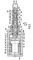
- FIGS. 2A and 2B show in detail, according to one example, an exchange valve 24 and a control valve 46 of the aforementioned type.
- the exchange valve 24, shown in the closed position in FIG. 2A comprises a valve body 62 having an inlet 62A adapted to be connected to one of the main ducts 12 or 14 or to the duct 22 of FIG. 1, and an output 62B adapted to be connected to the tank without pressure 26.
- the movable member of this exchange valve 24, in this case a valve spool 64 is movable in this valve body 62 between a first open position in which it isolates the inlet 62A of the valve exchange 24 of the output 62B of the latter and a second position (shown in Figure 2B) in which it connects said input 62A and 62B output.
- These input and output 62A and 62B of the body 62 form the input and output 24A and 24B evoked in connection with FIG.
- the spring 145 tends to push the slide 64 against a shoulder 62C formed in the valve body 62 in the direction of arrow F1 to its closed position in which It obstructs the outlet 62B.
- the opening control chamber 66A of the exchange valve 24 is located at the end 64A of the slide 64 which is close to the inlet 62A of the valve body 62, while the closing control chamber 66B is located at the other end 64B of this drawer 64.
- the two control chambers 66A and 66B communicate with each other by a hole in the slide 64, in this case a connecting pipe 68.
- This connecting pipe 68 includes the restriction 54 for limiting the flow rate of fluid entering the control chamber closing 66B and thus create a pressure drop between the opening 66A and closing 66B chambers.
- the pipe 68 thus forms the pipes 142, 52A and 52B evoked in relation with FIG.
- the control valve 46 comprises a control valve having a ball and a seat, which makes it possible to connect the closing control chamber 66B of the exchange valve 24 to the tank without pressure or to isolate this chamber 66B from the tank.
- This valve comprises a ball 70 which is disposed in the valve body 62 so as to cooperate against a seat 72 forming a stop integral with the valve body 62.
- the seat 72 is formed at the end of a sleeve 72 'held fixed in the valve body 62 by a snap ring 73.
- a rod 74 cooperating with this ball 70 is adapted according to a threshold of the parameter P, to urge the ball 70 in the direction indicated by the arrow F1 to move the ball 70 from its seat 72, while the elastic control return means, in this case the spring 55, constantly urge the ball 70 in the opposite direction, indicated by the arrow F2, towards its closed position.
- the spring 55 is advantageously a conical spring whose top 55A supports the ball 70.
- the ball 70 bears against the top 55A of the spring 55, while the other end 55B of the spring 55, forming its base, bears against an element 76 held fixed in the valve body 62 by a snap ring. stop 76 '.
- This element 76 is provided with a bore 76A allowing the fluid coming from the connecting pipe 68 to flow to the enclosure that contains the ball 70. It follows that the closing control chamber 66B extends from both sides of this piercing 76A.
- the rod 74 cooperates with a temperature-sensitive member 84, in this case the rod 74 and said member 84 form the actuator 144, the rod 74 being displaceable in the direction of the arrows F1 or F2 in a function of the value of the first control parameter P, which is in this case a temperature taken in a chamber 144 ', to request the passage of the control valve 46 between its closed position and its open position.
- the actuator is a thermosensitive element 144, such as a thermal cylinder. It may also be an electric or electromechanical actuator controlled by an electronic control unit.
- the chamber 144 ' is naturally filled by the fluid present in the motor housing.
- the actuator can react to a parameter other than the temperature and in particular other than the temperature of a fluid, for example the fluid pressure in another part of the product than the main pipe which is at the lowest pressure, the temperature engine crankcase, active engine displacement, etc.).
- the actuator 144 is integral with the valve body 62. In this case, it is held against the valve body 62 via the sleeve 72 'and a cap 78 sealingly secured in a sleeve 80 disposed in the hydraulic motor housing (not shown). It is understood that at one end 80A, the sleeve 80 is closed by the plug 78, while at its other end 80B, it has a bore 80 'in which the valve body 62 is disposed with a clearance e allowing the fluid passage between the enclosure of the motor housing and the chamber 144 '.
- the sleeve 72 ' has a bore 72A in which the rod 74 is movable and a passage 72B which communicates this passage 72A with the chamber 144'.
- the seat 72 of the ball 70 is located at the end of the bore 72A closing control chamber side 66B, so that the position of the ball 70 prohibits or allows the connection between the passage 72B and said chamber 66B.
- the passage 72B is in relation to the pressure-free reservoir 26 (shown in FIG. 1) via the chamber 144 'and the gap e existing between the sleeve 80 and the valve body 62, allowing the contained fluid in the closing control chamber 66B to escape to this reservoir, when the ball 70 is moved away from the seat 72 by the rod 74.
- Figure 3 illustrates a variant of the control valve of Figure 2A in the closed position.
- the slide 64 and the actuator 144 are identical to those described above and operate in the same way, so that they are not the subject of the following description. All elements common to Figure 3 and Figures 2A and 2B have the same references as in these figures.
- FIG. 3 differs from that of FIGS. 2A and 2B in that the exchange return spring for biasing the slide 64 of the exchange valve 224 and the control return spring are formed by a same spring 245.
- the ball assembly 70, conical spring 55 and fixed element 76, is now replaced by a single movable element 270 which is able to move to an open position, in the direction of the arrow F1, position in which it allows the fluid contained in the closing control chamber 266B to escape to the tank without pressure or to a closed position, in the direction of arrow F2, in which position the fluid in said chamber 266B is isolated from the reservoir.
- Figure 3 illustrates the closing position of the movable member 270.
- This movable member 270 has a shoulder 270A against which the spring 245 is supported by one of its ends 245A (its other end 245B bearing against the slide 64) and a sealing surface 270B, opposite the shoulder 270A and adapted to bear against the seat 272 formed at the end of a sleeve 272 'fixed by a snap ring 73 in the valve body 262.
- the action of this spring 245 and the pressure of the fluid contained in the closing control chamber 266B tends to urge movement of the movable member 270 in the direction of the arrow F2 towards the closed position of the control valve.
- the sleeve 272 ' has a passage 2728 allowing, when the movable member 270 is spaced from the seat 272 by the rod 74 of the actuator 144, to connect the closing control chamber 266B drilling 272A of the sleeve 272 ', and therefore, thanks to the game e, to the reservoir.
- the rod 74 pushes the movable element 270 towards its open position, in the direction of arrow F1, until a shoulder 270C formed on this element 270, comes into abutment against a rod 276 'fixed in the valve body 262.
- This displacement of the movable element 270 causes compression of the spring 245.
- the shoulder 270C is spaced from the rod 276 'by a distance E chosen to allow mobility of the movable member 270 of its seat 272 to a sufficient distance to allow the escape of the fluid contained in the closing control chamber 266B.
- the body 84 of the actuator 144 can be movable.
- a compensation spring 82 abuts against a cap 278 and against the body 84 of the actuator 144, permanently pushing the latter against a shoulder 272 "of the sleeve 272 'and allowing the relative movement of the body 84 of the actuator 144 relative to the rod 74.
- this compensation spring 82 bears against one of its ends 82A against a washer 86, itself bearing against the body 84 of the actuator 144, while its other end 82B bears against a shoulder 278A formed in the cap 278.
- the sleeve 80 containing the actuator 144, the control valve and the exchange valve is fixed, for example by screwing, in a bore of the hydraulic motor housing.
- the selector 20 can be integrated with the hydraulic motor, its output 22 being directly connected to the inlet 62A of the exchange valve.
- the same arrangements can be applied to the housing of the main pump of the hydraulic motor.
Landscapes
- Engineering & Computer Science (AREA)
- General Engineering & Computer Science (AREA)
- Mechanical Engineering (AREA)
- Chemical & Material Sciences (AREA)
- Analytical Chemistry (AREA)
- Physics & Mathematics (AREA)
- Fluid Mechanics (AREA)
- Fluid-Pressure Circuits (AREA)
- Multiple-Way Valves (AREA)
Claims (20)
- Kreislauf mit einer Austausch- und/oder Spülvorrichtung und wenigstens einem Hydraulikmotor (16) mit einem Gehäuse, das einen Innenraum begrenzt, in dem der Zylinderblock des Motors angeordnet ist, und zwei Hauptleitungen (12, 14), die mit einer Hauptpumpe (10) verbunden sind und eine Hauptzulaufleitung bzw. eine Hauptablaufleitung für den Hydraulikmotor (16) bilden, wobei die Austausch- und/oder Spülvorrichtung ein Austauschventil (24; 224) aufweist, das mit wenigstens einer der Hauptleitungen (12, 14) verbunden ist und eine geöffnete Stellung, in der es eine Verbindung zwischen der Hauptleitung (12, 14), mit der es verbunden ist, und einem druckfreien Behälter (26) herstellt, und eine geschlossene Stellung einzunehmen vermag, in der es diese Verbindung unterbricht, wobei die Vorrichtung Mittel (46, 60, 140, 246) aufweist, um den Wechsel des Austauschventils (24; 224) zwischen der geöffneten und der geschlossenen Stellung in Abhängigkeit wenigstens eines Steuerparameters (P) zu betätigen, der einen Zustand des Kreislaufs darstellt, der nicht dem Druck in der Hauptleitung (12, 14) entspricht, mit der das Austauschventil (24; 224) verbunden ist,
dadurch gekennzeichnet, dass das Austauschventil ein Element (64) aufweist, das zwischen einer ersten Position und einer zweiten Position beweglich ist, die der geschlossenen bzw. der geöffneten Stellung des Austauschventils entspricht, dass die Vorrichtung ein Steuerventil (46, 246) aufweist, das in Abhängigkeit von dem wenigstens einen Steuerparameter betätigt wird, um das Verschieben des beweglichen Elements (64) zu gestatten, dass sie einen Öffnungssteuerraum (66A) umfasst, der in der Lage ist, durch eine erste Verbindungsleitung (142) mit einer der Hauptleitungen (12, 14) verbunden zu werden, um das bewegliche Element (64) in seine zweite Position zu drängen, in der die Hauptleitung mit dem Behälter verbunden ist, sowie einen Schließsteuerraum (66B, 266B), der in der Lage ist, mit einem unter Druck stehenden Raum verbunden zu werden, um das bewegliche Element (64) in seine erste Position zu drängen, und dass das Steuerventil (46, 246) in Abhängigkeit von dem wenigstens einen Steuerparameter betätigt wird, um den Schließsteuerraum (66B, 266B) mit dem druckfreien Behälter zu verbinden oder um diesen Raum von diesem Behälter abzusperren. - Kreislauf nach Anspruch 1,
dadurch gekennzeichnet, dass der einen Zustand des Kreislaufs darstellende Steuerparameter (P) aus dem Fluiddruck in einer Nebenleitung des Kreislaufs, der Fluidtemperatur in einem Bereich des Kreislaufs, der Rotorgeschwindigkeit des Motors, der Rotorbeschleunigung oder der Rotorverzögerung, dem aktiven Hubvolumen des Motors, dem Einschlagwinkel eines durch den Hydraulikmotor angetriebenen Fahrzeugs, der Nutzung der Fördermenge einer Hilfspumpe durch die Betätigung eines Hilfsgeräts, der Laufrichtung des Motors und einer Bremssituation ausgewählt ist. - Kreislauf nach Anspruch 1 oder 2,
dadurch gekennzeichnet, dass er einen Steller (144) aufweist, der in der Lage ist, das Steuerventil (46; 246) in Abhängigkeit von einem Grenzwert des wenigstens einen Steuerparameters (P) zu betätigen. - Kreislauf nach Anspruch 3,
dadurch gekennzeichnet, dass der Steller (144) in der Lage ist, das Steuerventil (46, 246) in Abhängigkeit von der Temperatur in einem Bereich (144') des Kreislaufs zu betätigen. - Kreislauf nach Anspruch 4,
dadurch gekennzeichnet, dass er ein temperaturempfindliches Organ aufweist, das mit dem Steller (144) zusammenwirkt, und dass er in der Nähe des Gehäuses angeordnet ist. - Kreislauf nach einem der Ansprüche 1 bis 5,
dadurch gekennzeichnet, dass er einen Austauschwähler (20) umfasst, der in der Lage ist, eine Verbindung zwischen der unter niedrigstem Druck stehenden Hauptleitung (12, 14) und dem Austauschventil (24; 224) herzustellen. - Kreislauf nach Anspruch 6,
dadurch gekennzeichnet, dass der Öffnungs- und der Schließsteuerraum (66A, 66B; 266B) mit Verbindungsleitungen (142, 52A, 52B; 68, 76A; 276A) verbunden sind, die in der Lage sind, über den Austauschwähler (20) mit der unter niedrigstem Druck stehenden Hauptleitung (12, 14) verbunden zu werden. - Kreislauf nach einem der Ansprüche 1 bis 7,
dadurch gekennzeichnet, dass der Schließsteuerraum (66B; 266B) elastischen Austauschrückstellmitteln (145; 245) zugeordnet ist, die das bewegliche Element (64) ständig in seine erste Position drängen. - Kreislauf nach einem der Ansprüche 1 bis 8,
dadurch gekennzeichnet, dass die Verbindungsleitung (52B; 68) des Schließsteuerraums (66B; 266B) eine Drosselung (54) aufweist. - Kreislauf nach Anspruch 9,
dadurch gekennzeichnet, dass der Schließsteuerraum (66B, 266B) durch die Drosselung (54) mit dem Öffnungssteuerraum (66A) verbunden ist. - Kreislauf nach Anspruch 10,
dadurch gekennzeichnet, dass das Austauschventil (24, 224) einen Ventilkörper (62; 262) mit einem Eingang (62A), der mit einer der Hauptleitungen (12, 14) verbunden zu werden vermag, und mit einem Ausgang (62B) umfasst, der in der Lage ist, mit dem drucklosen Behälter (26) verbunden zu werden vermag, dass das bewegliche Element (64) in diesem Ventilkörper angeordnet ist und in seiner ersten Position den Eingang (62A) und den Ausgang (62B) absperrt, während es in seiner zweiten Position den Eingang (62A) und den Ausgang (62B) miteinander verbindet, und dass der Öffnungssteuerraum (66A) an einem Ende (64A) des beweglichen Elements (64) angeordnet ist, das dem Eingang (62A) des Ventilkörpers (62) benachbart ist, während der Schließsteuerraum (66B; 266B) an dem anderen Ende (64B) des beweglichen Elements (64) angeordnet ist und mit dem Öffnungssteuerraum (66A) durch eine Bohrung (68) des beweglichen Elements (64), in der die Drosselung (54) angeordnet ist, in Verbindung steht. - Kreislauf nach Anspruch 11,
dadurch gekennzeichnet, dass das Steuerventil (46; 246) eine Steuerklappe (70; 270) aufweist, die wenigstens zum Teil in dem Ventilkörper (62; 262) angeordnet ist. - Kreislauf nach einem der Ansprüche 1 bis 12,
dadurch gekennzeichnet, dass das Steuerventil (46; 246) eine Steuerklappe (70; 270) aufweist, die eine Öffnungsstellung einzunehmen vermag, in der sie den Schließsteuerraum (66B; 266B) mit dem drucklosen Behälter (26) verbindet, sowie eine Schließstellung, in der sie den Raum (66B; 266B) vom Behälter (26) absperrt. - Kreislauf nach Anspruch 13,
dadurch gekennzeichnet, dass er elastische Betätigungsrückstellmittel (55; 245) umfasst, die die Steuerklappe (70; 270) ständig in ihre Schließstellung drängen. - Kreislauf nach Anspruch 3 und Anspruch 13 oder 14,
dadurch gekennzeichnet, dass das Stellelement (144) mit der Steuerklappe (70, 270) zusammenzuwirken vermag, um letztere (70; 270) in ihre Öffnungsstellung zu drängen. - Kreislauf nach Anspruch 11 und einem der Ansprüche 3 bis 5 und 11 bis 15,
dadurch gekennzeichnet, dass der Steiler (144) und/oder das temperaturempfindliche Organ mit dem Ventilkörper (62; 262) fest verbunden sind. - Kreislauf nach Anspruch 16,
dadurch gekennzeichnet, dass sich der Steller (144) und/oder das temperaturempfindliche Organ in dem Ventilkörper (62; 262) zu bewegen vermögen und durch ein elastisches Rückstellmittel ständig zu einem Anschlag (72; 272) gedrängt werden, der mit dem Ventilkörper (62; 262) fest verbunden ist. - Kreislauf nach einem der Ansprüche 1 bis 17,
dadurch gekennzeichnet, dass das Steuerventil (46; 246) ein Proportionalventil ist. - Kreislauf nach Anspruch 11 und nach einem der Ansprüche 1 bis 18,
dadurch gekennzeichnet, dass der Ventilkörper (62; 262) in einer Bohrung des Gehäuses angeordnet ist. - Kreislauf nach einem der Ansprüche 1 bis 19,
dadurch gekennzeichnet, dass das Austauschventil (24; 224) einen Ausgang (62B) hat, der mit dem drucklosen Behälter (26) durch den Innenraum des Gehäuses verbunden ist.
Priority Applications (1)
| Application Number | Priority Date | Filing Date | Title |
|---|---|---|---|
| EP05077744A EP1643139B1 (de) | 2002-10-28 | 2003-10-28 | Spülventilvorrichtung |
Applications Claiming Priority (3)
| Application Number | Priority Date | Filing Date | Title |
|---|---|---|---|
| FR0213438A FR2846386B1 (fr) | 2002-10-28 | 2002-10-28 | Dispositif d'echange et/ou de balayage pour un circuit comprenant au moins un moteur hydraulique |
| FR0213438 | 2002-10-28 | ||
| PCT/FR2003/003199 WO2004040147A1 (fr) | 2002-10-28 | 2003-10-28 | Dispositif d'echange et/ou de balayage pour un circuit comprenant au moins un moteur hydraulique |
Related Child Applications (1)
| Application Number | Title | Priority Date | Filing Date |
|---|---|---|---|
| EP05077744A Division EP1643139B1 (de) | 2002-10-28 | 2003-10-28 | Spülventilvorrichtung |
Publications (2)
| Publication Number | Publication Date |
|---|---|
| EP1556619A1 EP1556619A1 (de) | 2005-07-27 |
| EP1556619B1 true EP1556619B1 (de) | 2006-03-01 |
Family
ID=32088316
Family Applications (2)
| Application Number | Title | Priority Date | Filing Date |
|---|---|---|---|
| EP03778478A Expired - Fee Related EP1556619B1 (de) | 2002-10-28 | 2003-10-28 | Spülvorrichtung für einen kreislauf mit mindestens einem hydraulischen motor |
| EP05077744A Expired - Fee Related EP1643139B1 (de) | 2002-10-28 | 2003-10-28 | Spülventilvorrichtung |
Family Applications After (1)
| Application Number | Title | Priority Date | Filing Date |
|---|---|---|---|
| EP05077744A Expired - Fee Related EP1643139B1 (de) | 2002-10-28 | 2003-10-28 | Spülventilvorrichtung |
Country Status (6)
| Country | Link |
|---|---|
| US (1) | US7231764B2 (de) |
| EP (2) | EP1556619B1 (de) |
| AU (1) | AU2003285477A1 (de) |
| DE (2) | DE60321055D1 (de) |
| FR (1) | FR2846386B1 (de) |
| WO (1) | WO2004040147A1 (de) |
Families Citing this family (12)
| Publication number | Priority date | Publication date | Assignee | Title |
|---|---|---|---|---|
| FR2861448B1 (fr) * | 2003-10-28 | 2006-02-10 | Poclain Hydraulics Ind | Dispositif de transmission hydrostatique d'un engin mobile avec echange |
| CN100414144C (zh) * | 2005-12-19 | 2008-08-27 | 大连海事大学 | 一种低速大扭矩的液压驱动与自制动系统 |
| DE202007006933U1 (de) * | 2007-05-15 | 2008-08-21 | Burgmann Industries Gmbh & Co. Kg | Durchflusssperrventil |
| US8578707B2 (en) * | 2009-04-14 | 2013-11-12 | Paragon Tank Truck Equipment, Llc | Protection valve for hydraulic drive system |
| CN102734268B (zh) * | 2012-06-21 | 2015-02-18 | 三一重工股份有限公司 | 工程机械及对液压马达泄油油路预热的方法和液压系统 |
| FR3003909B1 (fr) * | 2013-03-29 | 2015-04-03 | Hp2S | Dispositif de decompression hydraulique |
| CN104385915A (zh) * | 2014-09-23 | 2015-03-04 | 徐州重型机械有限公司 | 制动能量回收利用系统、回收利用方法及起重机 |
| DE102016214560A1 (de) * | 2016-08-05 | 2018-02-08 | Voith Patent Gmbh | Verfahren und Vorrichtung zum Reinigen und/oder Austausch von Hydrauliköl in hydraulischen Antrieben |
| DE102017215726A1 (de) | 2017-09-07 | 2019-03-07 | Robert Bosch Gmbh | Hydrostatische Ventilanordnung, hydrostatisches Getriebe mit der Ventilanordnung, und hydrostatischer Antrieb mit dem Getriebe |
| US11346083B1 (en) * | 2021-06-11 | 2022-05-31 | Caterpillar Inc. | Fluid flushing system for a hydraulic circuit of a work machine |
| CN113530909B (zh) * | 2021-07-19 | 2023-02-17 | 中航力源液压股份有限公司 | 用于闭式液压系统变量泵的多功能控制阀 |
| CN115773291B (zh) * | 2022-11-14 | 2023-06-02 | 中国船舶集团有限公司第七〇四研究所 | 一种带有冲洗回路的减摇鳍闭式液压系统 |
Family Cites Families (10)
| Publication number | Priority date | Publication date | Assignee | Title |
|---|---|---|---|---|
| US3174410A (en) * | 1962-05-21 | 1965-03-23 | Plessey Co Ltd | Relief valve devices for hydraulic power systems |
| CH454562A (de) * | 1967-05-02 | 1968-04-15 | Von Roll Ag | Spüleinrichtung für reversierbare hydrostatische Getriebe |
| US3891901A (en) * | 1970-02-24 | 1975-06-24 | Mallory & Co Inc P R | Capacitors with sprayed electrode terminals |
| IT1071280B (it) * | 1976-05-17 | 1985-04-02 | Fiat Allis Macch Movi | Sistema idraulico per macchine permovimento di terra e valvola termostatica per detto sistema |
| DE2932481A1 (de) * | 1979-08-10 | 1981-03-26 | Robert Bosch Gmbh, 70469 Stuttgart | Steuerventil |
| US4354351A (en) * | 1980-09-29 | 1982-10-19 | Caterpillar Tractor Co. | Load sensing steering |
| US5666807A (en) * | 1995-12-13 | 1997-09-16 | Caterpillar Inc. | Oil processor circuit |
| DE19930056C1 (de) * | 1999-06-30 | 2001-01-25 | Sauer Sundstrand Gmbh & Co | Anordnung zum Steuern eines hydraulischen Fahrantriebs |
| CN1277330C (zh) * | 1999-08-10 | 2006-09-27 | 三洋电机株式会社 | 非水电解液二次蓄电池及其制造方法 |
| US6336325B1 (en) * | 1999-12-07 | 2002-01-08 | Sauer-Danfoss Inc. | Hydrostatic loop dump valve for reducing input torque required by hydrostatic unit |
-
2002
- 2002-10-28 FR FR0213438A patent/FR2846386B1/fr not_active Expired - Fee Related
-
2003
- 2003-10-28 DE DE60321055T patent/DE60321055D1/de not_active Expired - Lifetime
- 2003-10-28 DE DE60303816T patent/DE60303816T2/de not_active Expired - Lifetime
- 2003-10-28 WO PCT/FR2003/003199 patent/WO2004040147A1/fr not_active Application Discontinuation
- 2003-10-28 AU AU2003285477A patent/AU2003285477A1/en not_active Abandoned
- 2003-10-28 EP EP03778478A patent/EP1556619B1/de not_active Expired - Fee Related
- 2003-10-28 US US10/533,095 patent/US7231764B2/en not_active Expired - Fee Related
- 2003-10-28 EP EP05077744A patent/EP1643139B1/de not_active Expired - Fee Related
Also Published As
| Publication number | Publication date |
|---|---|
| US7231764B2 (en) | 2007-06-19 |
| DE60303816T2 (de) | 2006-11-09 |
| EP1643139A1 (de) | 2006-04-05 |
| DE60321055D1 (de) | 2008-06-26 |
| EP1643139B1 (de) | 2008-05-14 |
| DE60303816D1 (de) | 2006-04-27 |
| AU2003285477A1 (en) | 2004-05-25 |
| US20060053784A1 (en) | 2006-03-16 |
| FR2846386A1 (fr) | 2004-04-30 |
| EP1556619A1 (de) | 2005-07-27 |
| WO2004040147A1 (fr) | 2004-05-13 |
| FR2846386B1 (fr) | 2006-03-03 |
Similar Documents
| Publication | Publication Date | Title |
|---|---|---|
| EP1556619B1 (de) | Spülvorrichtung für einen kreislauf mit mindestens einem hydraulischen motor | |
| EP2440806B1 (de) | Stossdämpfer und mit solch einem stossdämpfer versehenes fahrwerk | |
| EP1154170B1 (de) | Einrichtung zum Bremsen eines Rotors gegenüber einem Stator | |
| EP3480458B1 (de) | Hydraulische maschine, die ein verbessertes bremssystem umfasst | |
| FR2467752A1 (fr) | Systeme de freinage hydraulique | |
| EP3308026B1 (de) | Hydrauliksystem mit entwässerter kammer | |
| WO2006016049A2 (fr) | Circuit hydraulique comprenant un selecteur multifonction | |
| EP1964740A1 (de) | Neuartige funktionelle Architektur eines Vakuumkreislaufs in einem Kraftfahrzeug zur Erhaltung der Integrität der pneumatischen Stellglieder oder Aufnehmer | |
| FR2478770A1 (fr) | Convertisseur de couple hydrodynamique muni de moyens de pontage | |
| FR2463034A1 (fr) | Appareil amplificateur de force hydraulique | |
| EP1097321B1 (de) | Ventileinrichtung für einen hydraulischen motor zum antreiben einer grossen trägheitsmasse | |
| EP2383456B1 (de) | Einfach wirkender Hydraulikzylinder | |
| FR2471524A1 (fr) | Dispositif hydrodynamique pour transmettre un couple mecanique, et notamment frein hydrodynamique | |
| FR2727476A1 (fr) | Cylindre de travail | |
| FR2749544A1 (fr) | Dispositif perfectionne de commande hydraulique d'un embrayage de vehicule automobile | |
| FR2620660A1 (fr) | Regulateur de niveau pour vehicule automobile | |
| FR2819024A1 (fr) | Dispositif de moteur hydraulique ayant un selecteur de cylindree et un systeme de freinage | |
| EP0725226B1 (de) | Scheibenbremse mit verringerter Absorption | |
| FR2819023A1 (fr) | Circuit de prelevement comprenant une valve de prelevement pour echange et/ou balayage du carter d'un moteur hydraulique | |
| EP1777430B1 (de) | Hydraulische Kupplungssteuervorrichtung | |
| FR2820186A1 (fr) | Dispositif d'echange pour un circuit ferme | |
| EP1375951A1 (de) | Kupplungssteuerungssystem | |
| FR2847309A1 (fr) | Systeme d'actionnement avec commande de la course | |
| FR2492458A2 (fr) | Dispositif culbuteur de soupape deconnectable | |
| FR2834026A1 (fr) | Systeme de pilotage de l'ouverture/fermeture d'un embrayage par module de robotisation |
Legal Events
| Date | Code | Title | Description |
|---|---|---|---|
| PUAI | Public reference made under article 153(3) epc to a published international application that has entered the european phase |
Free format text: ORIGINAL CODE: 0009012 |
|
| 17P | Request for examination filed |
Effective date: 20050510 |
|
| AK | Designated contracting states |
Kind code of ref document: A1 Designated state(s): AT BE BG CH CY CZ DE DK EE ES FI FR GB GR HU IE IT LI LU MC NL PT RO SE SI SK TR |
|
| AX | Request for extension of the european patent |
Extension state: AL LT LV MK |
|
| GRAP | Despatch of communication of intention to grant a patent |
Free format text: ORIGINAL CODE: EPIDOSNIGR1 |
|
| DAX | Request for extension of the european patent (deleted) | ||
| RBV | Designated contracting states (corrected) |
Designated state(s): DE FR GB |
|
| GRAS | Grant fee paid |
Free format text: ORIGINAL CODE: EPIDOSNIGR3 |
|
| GRAA | (expected) grant |
Free format text: ORIGINAL CODE: 0009210 |
|
| AK | Designated contracting states |
Kind code of ref document: B1 Designated state(s): DE FR GB |
|
| REG | Reference to a national code |
Ref country code: GB Ref legal event code: FG4D Free format text: NOT ENGLISH |
|
| REF | Corresponds to: |
Ref document number: 60303816 Country of ref document: DE Date of ref document: 20060427 Kind code of ref document: P |
|
| GBT | Gb: translation of ep patent filed (gb section 77(6)(a)/1977) |
Effective date: 20060602 |
|
| PLBE | No opposition filed within time limit |
Free format text: ORIGINAL CODE: 0009261 |
|
| STAA | Information on the status of an ep patent application or granted ep patent |
Free format text: STATUS: NO OPPOSITION FILED WITHIN TIME LIMIT |
|
| 26N | No opposition filed |
Effective date: 20061204 |
|
| PGFP | Annual fee paid to national office [announced via postgrant information from national office to epo] |
Ref country code: GB Payment date: 20081010 Year of fee payment: 6 |
|
| PG25 | Lapsed in a contracting state [announced via postgrant information from national office to epo] |
Ref country code: GB Free format text: LAPSE BECAUSE OF NON-PAYMENT OF DUE FEES Effective date: 20091028 |
|
| PGFP | Annual fee paid to national office [announced via postgrant information from national office to epo] |
Ref country code: FR Payment date: 20141024 Year of fee payment: 12 Ref country code: DE Payment date: 20141010 Year of fee payment: 12 |
|
| REG | Reference to a national code |
Ref country code: DE Ref legal event code: R119 Ref document number: 60303816 Country of ref document: DE |
|
| PG25 | Lapsed in a contracting state [announced via postgrant information from national office to epo] |
Ref country code: DE Free format text: LAPSE BECAUSE OF NON-PAYMENT OF DUE FEES Effective date: 20160503 |
|
| REG | Reference to a national code |
Ref country code: FR Ref legal event code: ST Effective date: 20160630 |
|
| PG25 | Lapsed in a contracting state [announced via postgrant information from national office to epo] |
Ref country code: FR Free format text: LAPSE BECAUSE OF NON-PAYMENT OF DUE FEES Effective date: 20151102 |