EP1556278B1 - Verpackungssystem mit messen vom polster-füllmaterial - Google Patents
Verpackungssystem mit messen vom polster-füllmaterial Download PDFInfo
- Publication number
- EP1556278B1 EP1556278B1 EP03781713A EP03781713A EP1556278B1 EP 1556278 B1 EP1556278 B1 EP 1556278B1 EP 03781713 A EP03781713 A EP 03781713A EP 03781713 A EP03781713 A EP 03781713A EP 1556278 B1 EP1556278 B1 EP 1556278B1
- Authority
- EP
- European Patent Office
- Prior art keywords
- container
- void
- fill
- sensor
- dunnage
- Prior art date
- Legal status (The legal status is an assumption and is not a legal conclusion. Google has not performed a legal analysis and makes no representation as to the accuracy of the status listed.)
- Expired - Lifetime
Links
- 238000005259 measurement Methods 0.000 title description 4
- 238000004806 packaging method and process Methods 0.000 title description 3
- 239000011800 void material Substances 0.000 claims abstract description 34
- 238000000034 method Methods 0.000 claims abstract description 14
- 230000008569 process Effects 0.000 claims abstract description 10
- 239000000463 material Substances 0.000 claims description 57
- 230000004044 response Effects 0.000 claims description 6
- 238000003491 array Methods 0.000 claims description 2
- 239000000123 paper Substances 0.000 description 4
- 239000000523 sample Substances 0.000 description 4
- 241001553178 Arachis glabrata Species 0.000 description 3
- 235000020232 peanut Nutrition 0.000 description 3
- 239000004033 plastic Substances 0.000 description 3
- 238000012545 processing Methods 0.000 description 3
- 239000003637 basic solution Substances 0.000 description 2
- 235000017060 Arachis glabrata Nutrition 0.000 description 1
- 235000010777 Arachis hypogaea Nutrition 0.000 description 1
- 235000018262 Arachis monticola Nutrition 0.000 description 1
- 230000009471 action Effects 0.000 description 1
- 230000004075 alteration Effects 0.000 description 1
- 230000005540 biological transmission Effects 0.000 description 1
- 238000004891 communication Methods 0.000 description 1
- 238000010586 diagram Methods 0.000 description 1
- 239000002655 kraft paper Substances 0.000 description 1
- 238000012986 modification Methods 0.000 description 1
- 230000004048 modification Effects 0.000 description 1
- 230000003287 optical effect Effects 0.000 description 1
- 239000005022 packaging material Substances 0.000 description 1
- 238000012856 packing Methods 0.000 description 1
- 239000002984 plastic foam Substances 0.000 description 1
- 230000001681 protective effect Effects 0.000 description 1
Images


Classifications
-
- B—PERFORMING OPERATIONS; TRANSPORTING
- B65—CONVEYING; PACKING; STORING; HANDLING THIN OR FILAMENTARY MATERIAL
- B65B—MACHINES, APPARATUS OR DEVICES FOR, OR METHODS OF, PACKAGING ARTICLES OR MATERIALS; UNPACKING
- B65B55/00—Preserving, protecting or purifying packages or package contents in association with packaging
- B65B55/20—Embedding contents in shock-absorbing media, e.g. plastic foam, granular material
-
- B—PERFORMING OPERATIONS; TRANSPORTING
- B65—CONVEYING; PACKING; STORING; HANDLING THIN OR FILAMENTARY MATERIAL
- B65B—MACHINES, APPARATUS OR DEVICES FOR, OR METHODS OF, PACKAGING ARTICLES OR MATERIALS; UNPACKING
- B65B61/00—Auxiliary devices, not otherwise provided for, for operating on sheets, blanks, webs, binding material, containers or packages
- B65B61/20—Auxiliary devices, not otherwise provided for, for operating on sheets, blanks, webs, binding material, containers or packages for adding cards, coupons or other inserts to package contents
- B65B61/22—Auxiliary devices, not otherwise provided for, for operating on sheets, blanks, webs, binding material, containers or packages for adding cards, coupons or other inserts to package contents for placing protecting sheets, plugs, or wads over contents, e.g. cotton-wool in bottles of pills
-
- Y—GENERAL TAGGING OF NEW TECHNOLOGICAL DEVELOPMENTS; GENERAL TAGGING OF CROSS-SECTIONAL TECHNOLOGIES SPANNING OVER SEVERAL SECTIONS OF THE IPC; TECHNICAL SUBJECTS COVERED BY FORMER USPC CROSS-REFERENCE ART COLLECTIONS [XRACs] AND DIGESTS
- Y10—TECHNICAL SUBJECTS COVERED BY FORMER USPC
- Y10S—TECHNICAL SUBJECTS COVERED BY FORMER USPC CROSS-REFERENCE ART COLLECTIONS [XRACs] AND DIGESTS
- Y10S493/00—Manufacturing container or tube from paper; or other manufacturing from a sheet or web
- Y10S493/967—Dunnage, wadding, stuffing, or filling excelsior
Definitions
- the invention herein described relates generally to a packaging system for providing a controlled quantity of dunnage material for top-filling a container in which one or more objects are packed for shipping.
- dunnage material In the process of shipping one or more articles, products or other objects in a container, such as boxes/cartons, from one location to another, a protective packaging material or other type of dunnage material is typically placed in the shipping container to fill any voids and/or to cushion the item during the shipping process.
- Some commonly used dunnage materials are plastic foam peanuts, plastic bubble pack, air bags and converted paper dunnage material.
- the dunnage material is used to top-fill a container in which one or more objects have been placed, thereby to fill any remaining void in the container and thus prevent or minimize any shifting movement of the object or objects in the container during shipment.
- an automated dispenser is used to supply dunnage material for filling the box, perhaps the most prevalent practice today is for the operator of the dispenser to observe the container as it is being filled with dunnage material and stop the dispenser when the container appears to be full.
- Automated dispensers include, for example, plastic peanut dispensers often associated with an air delivery system, air bag machines and paper dunnage converters.
- a common tendency is for the operator to overfill the container, with the result that more dunnage material may have been placed in the container than was needed adequately to protect the object or objects packed in the container. In other instances, the operator may put too little dunnage material in the container with the result that the object or objects packed in the container can be damaged during shipment. Over-filling and under-filling typically becomes more of a problem as the speed of the dispenser increases.
- the '429 patent discloses a packaging system comprising a probe for sensing the void in a container and a dunnage converter having a controller for controlling the feeding and cutting of a strip of dunnage material such that there is produced the amount of dunnage material needed to fill the void in the container.
- a mechanical probe may be used to probe a container in one or more locations to determine the amount of dunnage material needed to fill the void.
- the mechanical probe may also be used in conjunction with a bar code reader or used in conjunction with or supplanted by sensors which sense the dimensions or degree of fill of the container, including optical and ultrasonic sensors.
- the present invention provides a system, and associated components and methodology, that provides for automatic determination and supply of an amount of dunnage material sufficient to fill the void left in a container in which one or more objects have been placed.
- such a system comprises a dunnage dispenser which is operable to dispense a controlled amount of a dunnage material, a container scanner having a scan area, and a logic device.
- the container scanner includes a height sensor for sensing a height characteristic of a container, a width sensor for sensing a width characteristic of the container, and a contour sensor for sensing a contour characteristic of the one or more objects in the container.
- the logic device is operable (1) to process sensed characteristic information received from the height sensor, width sensor and contour sensor, (2) to determine the amount of dunnage material needed to fill the void left in the container not occupied by the one or more objects, and (3) to command the dunnage dispenser to dispense the determined amount of dunnage material.
- a conveyor conveys the container through the scan area
- the logic device calculates a length characteristic of the container as a function of the sensed characteristic information received from at least one of the sensors and the rate at which the conveyor conveys the container through the scan area.
- the contour sensor may continuously sense the top surface of the one or more objects in the container as the container is moved through the scan area by the conveyor.
- a void-fill system for automatically determining and producing an amount of dunnage material sufficient to fill the void left in a container in which one or more objects have been placed, comprises a dunnage dispenser which is operable to dispense a controlled amount of a dunnage material; a void-measuring apparatus which measures the amount of void left in a container after one or more objects have been placed in the container, the void-measuring apparatus being operative to command the dunnage dispenser to dispense a prescribed amount of dunnage material; and an input device connected to the void-measuring apparatus that enables selection of a void-fill density from a plurality of void-fill densities, and wherein the void-measuring apparatus, in response to a selected void-fill density, varies the amount of dunnage material that the dunnage dispenser is commanded to dispense per measured volume of void, thereby to obtain the selected void-fill density.
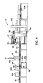
- an exemplary void-fill measuring and dispensing system is indicated generally at 10.
- the system 10 is operative to automatically determine and supply an amount of dunnage material sufficient to fill the void left in a container in which one or more objects have been placed.
- the system 10 generally comprises a dunnage dispenser 12 which is operable to dispense a controlled amount of a dunnage material, a container scanner 14 having a scan area 16, and a container conveyor 18 for conveying a container through the scan area.
- the container conveyor (which may form at least part of a packing line conveyor) preferably has a powered section 20 and an un-powered section 22.
- the powered section 20 extends at least from a container holding station 24, through the scan area 16 and to the un-powered section 22.
- the un-powered section 22 extends from the powered section 20 through a dunnage fill area 26 proximate the dunnage dispenser 12.
- the conveyor 18 can be of any suitable type such as the illustrated roller conveyor.
- the conveyor 18 has associated therewith a stop gate 30 of any suitable type for controllably permitting passage of containers into the scan area 16.
- the stop gate 30 is a retractable stop member which in an extended position will block passage of a container 32a and thereby hold the container 32a at the holding station.
- the stop member 30 is retracted, the container 32a is allowed to move out of the holding station 24 by the action of the powered section 20 of the conveyor 18.
- the stop member 30 is extended to capture and hold the next container 32b at the holding station 24, whereby containers are controllably fed into and through the scan area 16.
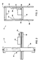
- the exemplary container scanner 14 can be seen to include a frame 38 having a pair of uprights straddling the container conveyor 18 and a cross beam 40 supported atop the uprights at a fixed distanced from the container conveyor 18.
- the uprights for example, can be floor supported as shown in FIGS. 2 and 3, or can be mounted to the conveyor 18 as illustrated in FIG. 1.
- the container scanner 14 further comprises one or more sensors which may be infrared, ultrasonic, laser or other type of sensors.
- the sensors are a height sensor 44 for sensing a height characteristic of a container, a width sensor 46 for sensing a width characteristic of the container, and a contour sensor 48 for sensing a contour characteristic of the one or more objects in the container.
- the contour sensor 48 shown mounted to the cross beam 40 above the scan area 16, preferably is of a type that continuously senses the top surface of the one or more objects in the container, such as container 32c, as the container is moved through the scan area 16 by the conveyor.
- An exemplary contour sensor is a non-contact optic laser scanner that operates by measuring the time of flight of laser light pulses, such as the Sick Optic LMS 200-30106 laser scanner. A pulsed laser beam is emitted by the laser scanner and reflected if it meets an object. The reflection is registered by the laser scanner's receiver. The time between transmission and reception of the reflected impulse is directly proportional to the distance between the laser scanner and the object.
- the pulsed laser beam can be deflected by an internal rotating mirror so that a fan-shaped scan is made of the surrounding area, whereupon the contour of the object (i.e., distance from a fixed reference point/plane) is determined from the sequence of impulses received.
- the fan beam is oriented perpendicular to the movement path of the container through the scan area 16, whereby the contour of the objects is progressively measured as the container moves through the scan area 16.
- the measurement data can be supplied in real time via suitable communication means.
- the width sensor 46 can be any suitable sensor for measuring the width of the container passing through the scan area.
- the width sensor 46 is an infrared distance sensor that can be used to measure the distance a side of the container is spaced from the sensor or other reference point.
- the location of the other side of the container must be registered at a known fixed distance from the width sensor 46 which, as shown, can be mounted to one of the uprights of the scanner frame 38 at a location just above the level of the conveyor.
- the containers are registered against a guide rail 52 on the side of the conveyor 18 opposite the width sensor, which guide rail 52 is at a known distance from the width sensor and thus functions as a zero reference. Accordingly, the width of the container will be the difference between the location of the guide rail 52 and the measured location of the side of the container nearest the width sensor 46. Any suitable means may be employed to register the container against the guide rail 52.
- the height sensor 44 can be any suitable sensor for determining a height characteristic of the container in the scan area 16.
- An exemplary sensor 44 includes an array 56 of emitters and an array 58 of receivers disposed on opposite transverse sides of the scan area.
- the emitter and receiver arrays 56 and 58 are mounted respectively to the scanner frame uprights 38.
- Each array includes a row of emitters/receivers that is oriented perpendicular to the plane of the conveyor 18. Accordingly, the emitter array 56 produces a curtain of light that is sensed by the receiver array 58. As a container moves through the curtain, the curtain will be interrupted by the container up to the height of the container, whereby a measurement of the container height is obtained.
- the system 10 is configured for use with regular slotted containers (RSCs).
- RSCs regular slotted containers
- an RSC 62 has a specified relationship between the width of the container W and the height of the side flaps 64 and end flaps 66. That is, the flaps 64 and 66 have a height one half the width W of the container. Accordingly, the height H of the side walls 68 and end walls 70 of the container (i.e., the height of the container when closed) can be determined from a measure of the height of the container with the top flaps 64 and 66 upright in their unfolded state.
- the height of the side and end walls (the height of the object containing portion of the container) will be two thirds the height of the container when the top flaps 64 and 66 are upright and unfolded. While the illustrated embodiment measures the height of the container with the top flaps 64 and 66 upright and unfolded, those skilled in the art will appreciate that the height H can be otherwise measured, such as when the flaps 64 and 66 are folded down, thereby giving a direct measurement of the height of the side and end walls of the container.
- the container length is determined indirectly by measuring the length of time the container takes to pass any one of the sensors, such as the width sensor 46, and by knowing the speed at which the conveyor 18 is moving the container past the sensor. The length of time multiplied by the speed of the conveyor yields the length of the container. If the speed of the conveyor is a known constant, then only the length of time needs to be sensed in order to obtain the length of the container. If the speed of the conveyor varies or for other reasons, the conveyor speed sensor 96 can be used to sense the conveyor speed and communicate the same to the control unit 76 for processing.
- the speed sensor for example, can be an encoder interfaced with the conveyor drive motor for providing a series of pulses, the rate of which are proportional to the speed of the motor and thus the conveyor.
- the control unit can be calibrated to convert the pulse rate to a container speed that can be multiplied with the container passage time measured by the width sensor.
- the various operative components of the system 10 are controlled by a logic device 76 which is diagrammatically shown in FIG. 5.
- the various functions of the logic device 76 may be performed by a single controller, such as a control unit 78 for the container scanner 14. However, it may be desirable to distribute the functions of the logic device 76 among several controllers each having separate processors, such as among the control unit 78, the controller for the dunnage dispenser and/or a microprocessor of a personal computer 80.
- the logic device 76 encompasses the processor or processors of the system that control the operation of the system 10.
- the processor may be any one of a number of commercially available processors such as PLCs and general purpose processing chips with various output and input ports and associated memory devices including ROM and RAM.
- the logic device may be controlled by suitable software that among other things uses data received from the scanning sensors to determine container length, width, height and top void fill volume.
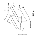
- the logic device 76 is operable to process sensed characteristic information received from the height sensor 44, width sensor 46 and contour sensor 48. The logic device 76 then determines the amount of dunnage material needed to fill the void left in the container above the one or more objects that have been placed in the container (or the bottom wall of the container if not overlain by an object). In FIG. 6, this void is illustrated by the cross-hatching 84 while the objects in the container 32 are indicated at 85-90. After the amount of dunnage material to top fill the container is determined, the logic device 76 commands the dunnage dispenser 12 to dispense automatically the determined amount of dunnage material. The dunnage material can flow directly into the container and/or be placed or guided by an operator into the container.
- the dunnage dispenser 12 is a dunnage converter which converts one or more plies of sheet stock material (typically kraft paper) into a relatively less dense dunnage material.
- Exemplary dunnage converters are shown in U.S. Patent No. 5,123,889 and in published PCT Patent Application No. PCT/US01/18678, published under International Publication No. WO 01/94107, which are hereby incorporated herein by reference in their entireties.
- Other types of dunnage dispensers can be used, such as other types of paper dunnage converters, dispensers for plastic peanuts, etc.
- dunnage converter the dunnage material can be produced on site and in response to a command from the logic device 76.
- control unit 78 can be interfaced with the dunnage dispenser 12 and with a personal computer 80 by RS-232 serial connections 81 a and 81 b.
- the control unit 78 is equipped with various ports for connection with the scanner sensors 44, 46 and 48, with a foot switch 94, with an optional conveyor speed sensor 96, with the stop gate 30 and with an operator panel 98.
- the foot switch 94 and operator panel 98 preferably are located in the vicinity of the dunnage dispenser 12 for use by the human operator/packer. Their function will become apparent from the following description of the operation of the system 10.
- containers 32 that contain one or more objects, such as products for shipping, are conveyed by the powered section 20 of the conveyor 18 towards the void-fill scanner 14.
- the containers are justified by suitable means to one side of the powered roller conveyor, and preferably against the guide rail 52 (FIGS. 2 and 3).
- the containers are stopped on the conveyor by the stop gate 30 before entering the scan area 16.
- the control unit 78 instructs the stop gate 30 to release the leading container for movement into and through the scan area 16.
- the stop gate is commanded back to its capture position to prevent the next container from moving to the scan area 16 until later commanded by the logic device 76.
- the container As the container moves through the scan area 16, it is scanned by the sensors 44, 46 and 48. After scanning, the container enters the non-powered section 22 of the conveyor where an operator can reach and then position the container in front of the outlet of the dunnage converter 12. The operator then steps on the foot switch 94 again to cause the apparatus to command the dunnage dispenser 12 to dispense the amount of dunnage material needed to top fill the container. After the container has been filled with dunnage, it can be passed on for further processing, such as through a container closer 102 and then onto a further powered conveyor 104.
- the dunnage converter or other dunnage dispenser can dispense the dunnage material in different ways.
- the dunnage material can be dispensed by the operator-initiated method described above, or, alternatively, the operator can stop the dunnage converter from dispensing dunnage material, if needed to catch up with the dunnage converter, for example, and then depress the foot switch again. The dunnage converter would then continue to dispense dunnage material until the determined amount of dunnage is produced and then automatically stop.
- the status of the operation can be indicated by suitable indicators on the operator panel 98.
- suitable indicators on the operator panel 98 there may be provided a power-on indicator, a scan-complete indicator, a scan-fault indicator and a converter-ready indicator.
- the foot switch 94 is enabled only when the converter-ready light is on and the scan-fault indicator light is off.
- the scan-fault indicator when lit may indicate a no-container-detected condition, a measured container size below minimum and/or above maximum, and/or a measured top void volume that is negative (no object in the container) or exceeds container volume (container overfull).
- the logic device 76 may also be equipped with one or more input devices such as a mouse, a keyboard, a keypad, a touch screen, etc.
- the operator panel 98 can be equipped with a touch screen as an input device, or the personal computer 80 may have a touch screen or other input device associated therewith. In this manner, a scan reset input is provided to enable the operator to clear a fault condition or reset the system for some other reason.
- the operator panel and/or personal computer can have a monitor for displaying the various indicators and/or other information, such as the measured dimension of the container, the total volume of the container, the volume of the contents of the container, and the volume of the void above the container contents..
- the operator panel and/or personal computer may be provided with a selector device enabling the selection of a void-fill density from a plurality of void-fill densities.
- the logic device 76 varies the amount of dunnage material to be dispensed per measured volume of void, thereby to provide the selected void-fill density. That is, the logic device 76 can be programmed to have a default setting where it will command X amount of dunnage to be dispensed for each unit volume of measured void.
- the operator may select a lower void-fill density where in response the logic device 76 will command, for example, 10% less dunnage material to be dispensed per given unit of measured top-fill void. This will result in a lower density fill of the container and will consume a smaller quantity of dunnage material.
- the operator may select a higher void-fill density where in response the logic device 76 will command say 10% more dunnage material to be dispensed per given unit of measured top-fill void.
- the input device may be a dial whereby a desired density can be dialed in, a mouse pointer, a touch screen with one or more input regions, a keyboard or keypad for entry of a desired void-fill density, etc.
Landscapes
- Engineering & Computer Science (AREA)
- Mechanical Engineering (AREA)
- Making Paper Articles (AREA)
- Basic Packing Technique (AREA)
- Length Measuring Devices By Optical Means (AREA)
- Container Filling Or Packaging Operations (AREA)
- Examining Or Testing Airtightness (AREA)
- Wrapping Of Specific Fragile Articles (AREA)
- Length Measuring Devices With Unspecified Measuring Means (AREA)
Claims (15)
- Ein Hohlraumfüllsystem (10) zum automatischen Bereitstellen und Ausgeben einer Menge von Polstennaterial, welche ausreichend ist, um den Hohlraum zu füllen, welcher in einem Behälter (32) verblieben ist, in dem eines oder mehrere Objekte platziert wurden, aufweisend:einen Polsterspender (12), welcher bereit ist, eine kontrollierte Menge an Polstennaterial auszugeben;einen Behälterscanner (14), welcher ein Scangebiet (16) aufweist, wobei der Behälterscanner einen Höhensensor (44) zum Erfassen einer Höheneigenschaft eines Behälters (32) umfasst, einen Breitensensor (46) zum Erfassen einer Breiteneigenschaft des Behälters, und einen Kontursensor (48) zum Erfassen einer Kontureigenschaft von dem einen oder den mehreren Objekten in dem Behälter; undeine Logikvorrichtung (76), welche bereit ist,erfasste Eigenschaftsinformationen, welche von dem Höhensensor (44), dem Breitensensor (46) und dem Kontursensor (48) empfangen wurden, zu verarbeiten;die Menge an Polstermaterial zu bestimmen, welche benötigt wird, um den in dem Behälter verbliebenen Hohlraum zu füllen, welcher nicht eingenommen wird durch das eine oder die mehreren Objekte; undden Polsterspender (12) anzuweisen, die bestimmte Menge an Polstermaterial auszugeben.
- Ein Hohlraumfüllsystem gemäß Anspruch 1, weiterhin aufweisend einen Förderer zum Befördern des Behälters durch das Scangebiet.
- Ein Hohlraumfüllsystem gemäß Anspruch 2, wobei die Logikvorrichtung eine Längeneigenschaft des Behälters berechnet als eine Funktion der erfassten Eigenschaftsinformationen, welche empfangen wurden von zumindest einem der Sensoren und der Rate, bei der der Förderer den Container durch das Scangebiet fördert.
- Ein Hohlraumfüllsystem gemäß Anspruch 2, wobei der Kontursensor kontinuierlich die obere Oberfläche des einen oder der mehreren Objekte in dem Behälter erfasst, wenn der Behälter von dem Förderer durch das Scangebiet bewegt wird.
- Ein Hohlraumfüllsystem gemäß einem der vorhergehenden Ansprüche, wobei der Breitensensor die Distanz misst, um die eine Seite des Containers beabstandet ist von einem Referenzpunkt.
- Ein Hohlraumfüllsystem gemäß einem der vorhergehenden Ansprüche, wobei der Breitensensor ein Infrarotdistanzsensor ist.
- Ein Hohlraumfüllsystem gemäß einem der vorhergehenden Ansprüche, wobei der Kontursensor ein optischer Laserscanner ist.
- Ein Hohlraumfüllsystem gemäß einem der vorhergehenden Ansprüche, wobei der Höhensensor ein Emitter-Array von Emittern umfasst, und ein Empfänger-Array von Empfängern, welche auf gegenüberliegenden transversalen Seiten des Scangebiets angeordnet sind.
- Ein Hohlraumfüllsystem gemäß Anspruch 8, weiterhin aufweisend einen Behälterförderer zum Befördern des Behälters durch das Scangebiet; und wobei der Behälterscanner einen Rahmen umfasst, welcher ein Paar von Pfosten aufweist, welche beiderseits des Behälterförderers angeordnet sind und einen Querbalken, welcher gelageil wird oben auf dem Pfosten bei einer festgelegten Distanz von dem Behälterförderer und wobei die Emitter und Empfänger-Arrays jeweils an den Pfosten befestigt sind und wobei der Kontursensor an dem Querbalken befestigt ist.
- Ein Hohlraumfüllsystem gemäß einem der Ansprüche 2 bis 9, weiterhin aufweisend ein Stoptor, welches dem Behälterförderer zugeordnet ist, um auf kontrollierte Weise den Durchlauf eines Behälters in das Scangebiet zu gestatten.
- Ein Hohlraumfüllsystem gemäß einem der vorhergehenden Ansprüche, weiterhin aufweisend eine Auswahlvorrichtung, welche verbunden ist mit der Logikvorrichtung zum Ermöglichen der Auswahl einer Hohlraumfülldichte aus einer Mehrzahl von Hohlraumfülldichten, und wobei die Logikvorrichtung, in Reaktion auf eine ausgewählte Hohlraumfülldichte, die Menge an Polstermaterial ändert, welche ausgegeben werden soll pro gemessenem Hohlraumvolumen, um dabei die ausgewählte Hohlraumdichte bereitzustellen.
- Ein Hohlraumfüllsystem (10) zum automatischen Bestimmen und Herstellen einer Menge von Polstermaterial, welche ausreicht, um den Hohlraum, welcher in einem Behälter (32) verblieben ist, zu füllen, in welchem eines oder mehrere Objekte platziert wurden, aufweisend:einen Polsterspender (12), welcher bereit ist, eine kontrollierte Menge an Polstennaterial auszugeben;ein Hohlraummessgerät (14, 76), welches die Menge an Hohlraum misst, welche in einem Behälter (32) verblieben ist, nachdem eines oder mehrere Objekte platziert wurden in dem Behälter, wobei das Hohlraummessgerät bereit ist, den Polsterspender (12) anzuweisen, eine vorgeschriebene Menge an Polstermaterial auszugeben; undein Eingabegerät, welches verbunden ist mit dem Hohlraummessgerät (14, 76), welches die Auswahl einer Hohlraumfülldichte aus einer Mehrzahl von Hohlraumfülldichten ermöglicht und wobei das Hohlraummessgerät, in Reaktion auf eine ausgewählte Hohlraumfülldichte, die Menge an Polstermaterial variiert, die der Polsterspender (12) pro gemessenem Volumen von Hohlraum ausgeben soll, um dabei die ausgewählte Hohlraumfülldichte zu erhalten.
- Ein Hohlraumfüllsystem gemäß Anspruch 12, wobei das Hohlraummessgerät umfasst:einen Behälterscanner, welcher ein Scangebiet aufweist, wobei der Behälterscanner einen Höhensensor umfasst, zum Erfassen einer Höheneigenschaft eines Behälters, einen Breitensensor zum Erfassen einer Breiteneigenschaft des Behälters, und einen Kontursensor zum Erfassen einer Kontureigenschaft von dem einen oder mehreren Objekten in dem Behälter; undeine Logikvorrichtung, welche bereit ist,erfasste Eigenschaftsinformationen, welche von dem Höhensensor, dem Breitensensor und dem Kontursensor empfangen wurden, zu verarbeiten;die Menge an Polstermaterial zu bestimmen, welche benötigt wird, um den in dem Behälter verbliebenen Hohlraum zu füllen, welcher nicht eingenommen wird durch das eine oder die mehreren Objekte, basierend auf der ausgewählten Hohlraumfülldichte; undden Polsterspender anzuweisen, die bestimmte Menge an Polstermaterial auszugeben.
- Ein Gerät zum automatischen Bestimmen einer Menge von Polstennaterial, welche ausreicht, um den Hohlraum zu füllen, welcher in einem Behälter (32) verblieben ist, in welchem eines oder mehrere Objekte platziert wurden, aufweisend:eine Logikvorrichtung (76); undeine Eingabevorrichtung, welche verbunden ist mit der Logikvorrichtung, welche die Auswahl einer Hohlraumfülldichte aus einer Mehrzahl von Hohlraumfülldichten ermöglicht; undwobei die Logikvorrichtung bereit ist,
erfasste Eigenschaftsinformationen von einem Behälter, in welchem eines oder mehrere Objekte platziert wurden, zu verarbeiten;
die Menge von Polstermaterial zu bestimmen, welche benötigt wird, um den in dem Behälter verbliebenen Hohlraum zu füllen, welcher nicht eingenommen wird durch eines oder mehrere Objekte, basierend auf der ausgewählten Hohlraumfülldichte; und
den Polsterspender (12) anzuweisen, die bestimmte Menge von Polstermaterial auszugeben. - Ein Gerät zum automatischen Bestimmen einer Menge von Polstermaterial, welche ausreicht, um den Hohlraum zu füllen, welcher in einem Behälter (32) verblieben ist, in dem eines oder mehrere Objekte platzieil wurden, aufweisend:einen Behälterscanner (14) mit einem Scangebiet (16), wobei der Behälterscanner einen Höhensensor (44) umfasst zum Erfassen einer Höheneigenschaft eines Behälters; einen Breitensensor (46) zum Erfassen einer Breiteneigenschaft des Behälters, und einen Kontursensor (48) zum Erfassen einer Kontureigenschaft von dem einen oder den mehreren Objekten in dem Behälter; undeine Logikvorrichtung (76), welche bereit ist,erfasste Eigenschaftsinformationen, welche empfangen wurden von dem Höhensensor (44), dem Breitensensor (46) und dem Kontursensor (48) zu verarbeiten;die Menge an Polstermaterial zu bestimmen, welche benötigt wird, um den Hohlraum, welcher in dem Behälter (32) verblieben ist, zu füllen, welcher nicht eingenommen wird durch das eine oder die mehreren Objekte; undden Polsterspender (12) anzuweisen, die bestimmte Menge von Polstermaterial auszugeben.
Applications Claiming Priority (3)
| Application Number | Priority Date | Filing Date | Title |
|---|---|---|---|
| US42308002P | 2002-11-01 | 2002-11-01 | |
| US423080P | 2002-11-01 | ||
| PCT/US2003/034930 WO2004041653A1 (en) | 2002-11-01 | 2003-11-03 | Packaging system with volume fill measurement |
Publications (2)
| Publication Number | Publication Date |
|---|---|
| EP1556278A1 EP1556278A1 (de) | 2005-07-27 |
| EP1556278B1 true EP1556278B1 (de) | 2006-06-21 |
Family
ID=32312599
Family Applications (1)
| Application Number | Title | Priority Date | Filing Date |
|---|---|---|---|
| EP03781713A Expired - Lifetime EP1556278B1 (de) | 2002-11-01 | 2003-11-03 | Verpackungssystem mit messen vom polster-füllmaterial |
Country Status (11)
| Country | Link |
|---|---|
| US (2) | US7337595B2 (de) |
| EP (1) | EP1556278B1 (de) |
| KR (1) | KR101151457B1 (de) |
| CN (1) | CN100457556C (de) |
| AT (1) | ATE330851T1 (de) |
| AU (1) | AU2003287473B2 (de) |
| CA (1) | CA2504124C (de) |
| DE (1) | DE60306407C9 (de) |
| ES (1) | ES2271669T3 (de) |
| MX (1) | MXPA05004523A (de) |
| WO (1) | WO2004041653A1 (de) |
Cited By (4)
| Publication number | Priority date | Publication date | Assignee | Title |
|---|---|---|---|---|
| DE102011000561A1 (de) | 2011-02-08 | 2012-08-09 | B & W Solutions GmbH | Verfahren und Vorrichtung zum Befüllen von Paketen mit einem Polstermaterial in Schüttgutform |
| US9533776B2 (en) | 2010-09-17 | 2017-01-03 | B & W Solutions GmbH | Method and device for filling packets with padding in the form of bulk material |
| DE102017109375A1 (de) * | 2017-05-02 | 2018-11-08 | Storopack Hans Reichenecker Gmbh | Verfahren zum Polstern von Gegenständen in einem Behälter, sowie Vorrichtung zum Polstern von Gegenständen in einem Behälter |
| WO2019174800A1 (de) | 2018-03-14 | 2019-09-19 | Storopack Hans Reichenecker Gmbh | Vorrichtung zum bewegen eines polstermittels in einen transportbehälter, sowie verfahren zum betreiben einer solchen vorrichtung |
Families Citing this family (33)
| Publication number | Priority date | Publication date | Assignee | Title |
|---|---|---|---|---|
| EP1786682B1 (de) * | 2004-08-04 | 2009-02-25 | Ranpak Corp. | Verpackungssystem und -verfahren |
| ATE502857T1 (de) * | 2004-11-02 | 2011-04-15 | Ranpak Corp | Automatisiertes system und verfahren zur abgabe von rieselfähigen polsterelementen |
| US7584592B2 (en) | 2005-08-04 | 2009-09-08 | Ranpak Corp. | Packaging system and method |
| DE602006012996D1 (de) * | 2005-08-19 | 2010-04-29 | Ranpak Corp | Verpackungssystem und verfahren zur erfassung von geschlossenen behältern |
| WO2007115256A2 (en) * | 2006-04-01 | 2007-10-11 | Ranpak Corp. | Packaging system and method with freight rate analysis |
| US7814733B2 (en) * | 2006-04-10 | 2010-10-19 | Ranpak Corp. | Packaging system with volume measurement |
| US7437860B2 (en) * | 2006-05-01 | 2008-10-21 | R.E.D. Stamp, Inc. | Stamp applicator with automatic sizing feature |
| US20080236108A1 (en) * | 2007-03-29 | 2008-10-02 | Parmley Steven M | Package Wrapping Machine with Detection of Lip Features of Trayed Products to be Wrapped |
| FR2919520B1 (fr) * | 2007-08-02 | 2011-01-07 | Savoye | Procede et machine combinee de coupe et de fermeture de caisses avec pose de sacs de calage |
| AU2009231924B2 (en) * | 2008-03-31 | 2014-04-03 | Ranpak Corp. | Manually-assisted void-fill dunnage dispensing system and method |
| US20090277139A1 (en) * | 2008-05-12 | 2009-11-12 | Storopack, Inc. | Automated System Of Protective Packaging |
| WO2009155101A1 (en) * | 2008-05-30 | 2009-12-23 | Ranpak Corp. | Packaging system and method with controlled dunnage dispensing |
| EP2382133B1 (de) * | 2008-11-24 | 2015-01-07 | Ranpak Corp. | Manuell unterstütztes hohlraumfüllpolsterabgabesystem und verfahren |
| IT1392529B1 (it) | 2008-12-31 | 2012-03-09 | Corradi | Apparecchiatura per l'erogazione e l'inserimento di materiale per imballaggio in contenitori e relativo metodo. |
| US8446247B2 (en) * | 2009-10-21 | 2013-05-21 | J&L Group International, Llc | Safety system |
| EP2407389B1 (de) * | 2010-07-14 | 2013-10-16 | Storopack Hans Reichenecker GmbH | Verfahren und Anordnung zum Verpacken von mindestens einem Artikel in einen Behälter sowie eine Vielzahl von Behältertypen zum Versenden von Artikeln |
| DE102011103836A1 (de) * | 2011-06-01 | 2012-12-06 | Khs Gmbh | Behältervolumenkontrolle vorlaufend zur Füllhöhenkontrolle |
| ES2411805B1 (es) * | 2011-12-02 | 2014-06-11 | Cartonajes Bernabeu, S.A. | Sistema de alimentacion automatica para maquinas flejadoras. |
| US9371147B2 (en) * | 2012-02-14 | 2016-06-21 | Storopack Hans Reichenecker Gmbh | Method and arrangement for packing at least one article in a container and plurality of types of containers for shipping articles |
| GB201210170D0 (en) * | 2012-06-08 | 2012-07-25 | Linkx Systems Ltd | Container sizing method and system |
| FI124705B (fi) * | 2012-07-12 | 2014-12-15 | Jomet Oy | Laitteisto pakkauslaatikon korkeuden säätämiseksi ja laatikon sulkemiseksi |
| EP3257765B1 (de) | 2012-09-18 | 2019-11-20 | Ranpak Corp. | Verfahren zur dosierung von füllmaterial |
| US9612583B1 (en) * | 2013-06-11 | 2017-04-04 | Amazon Technologies, Inc. | Packaging management |
| WO2016044767A1 (en) * | 2014-09-19 | 2016-03-24 | Chan Simon Cs | Dunnage system |
| US10850906B2 (en) * | 2015-03-04 | 2020-12-01 | Storopack, Inc. | Air cushion machine and method |
| CN108820385A (zh) * | 2018-07-13 | 2018-11-16 | 武汉智能装备工业技术研究院有限公司 | 一种缓冲气垫材料的智能填充装置 |
| CN115348937B (zh) * | 2020-03-17 | 2024-03-15 | 朗派公司 | 用于将垫料产品转移到包装容器的包装系统及方法 |
| CN111559545B (zh) * | 2020-05-27 | 2021-01-22 | 信丰彩创包装材料有限公司 | 一种任意形状易碎品包装装置 |
| CN112535870B (zh) * | 2020-06-08 | 2021-12-14 | 苏州麟琪程科技有限公司 | 应用脚踝检测的软垫供应系统及方法 |
| CN113063710B (zh) * | 2021-02-24 | 2022-11-08 | 上海市市政工程管理咨询有限公司 | 一种用于桥梁工程的桥梁裂缝测量装置 |
| US20230067806A1 (en) * | 2021-08-31 | 2023-03-02 | Intertape Polymer Corp. | Void identification for packaging and apparatuses and methods for using void identification |
| CN114148587B (zh) * | 2022-02-10 | 2022-04-26 | 徐州益和木业有限公司 | 一种板材加工物料包装装置 |
| KR102663827B1 (ko) * | 2022-05-31 | 2024-05-08 | 씨제이대한통운 (주) | 완충재 투입 장치 및 완충재 투입 방법 |
Family Cites Families (69)
| Publication number | Priority date | Publication date | Assignee | Title |
|---|---|---|---|---|
| DE274188C (de) | ||||
| US2109294A (en) * | 1934-02-07 | 1938-02-22 | Standard Knapp Corp | Case packing machine |
| US2101170A (en) * | 1935-03-25 | 1937-12-07 | Shellmar Products Co | Sheeter |
| US2569589A (en) * | 1949-02-28 | 1951-10-02 | Robert F Trissell | Belt reeler and cutter |
| US2882802A (en) * | 1956-10-29 | 1959-04-21 | Fox Paper Company | Crumpling device |
| US3377771A (en) * | 1964-12-14 | 1968-04-16 | Walter J. Schmidt Sr. | Apparatus for loading cans into cartons |
| US3509797A (en) * | 1967-05-22 | 1970-05-05 | Arpax Co | Mechanism for producing cushioning dunnage |
| US3709756A (en) * | 1968-11-12 | 1973-01-09 | Xerox Corp | Article processing apparatus with feeder shuttle disconnect |
| US3613522A (en) * | 1969-09-12 | 1971-10-19 | Arpax Co | Method of producing cushioning dunnage |
| US3603216A (en) * | 1970-02-09 | 1971-09-07 | Arpax Co | Method for producing cushioning dunnage |
| US3651465A (en) * | 1970-05-01 | 1972-03-21 | Parke Davis & Co | Method and apparatus for package inspection and verification |
| US3695133A (en) * | 1970-07-16 | 1972-10-03 | Euclid Products Co Inc The | Apparatus for cutting strip material in variable lengths |
| US3743140A (en) * | 1970-12-21 | 1973-07-03 | Diehl Mateer G Co | Filler apparatus with hopper and rotary feed mechanism for dispensing controlled volumes of materials |
| US3744360A (en) * | 1971-02-22 | 1973-07-10 | Cellu Prod Co | Method and apparatus for dispensing cellular web material |
| US3799039A (en) * | 1971-12-14 | 1974-03-26 | Ranpak Corp | Cushioning dunnage mechanism and method |
| US3760669B2 (en) * | 1972-02-23 | 1990-10-16 | Sheet material feeding and cutting apparatus and control system therefor | |
| DE2258546C2 (de) * | 1972-11-29 | 1982-10-21 | Siemens AG, 1000 Berlin und 8000 München | Einrichtung zur Papiervorschubüberwachung bei Druckern |
| US3819918A (en) * | 1973-03-19 | 1974-06-25 | Kratos | Electronic device for determining the height, width, length and volume of a container |
| US4071911A (en) * | 1975-04-22 | 1978-01-31 | Continental Can Co. Inc. | Machine control system with machine serializing and safety circuits |
| US4026198A (en) * | 1975-05-01 | 1977-05-31 | Ranpak Corporation | Cushioning dunnage mechanism, transfer cart therefor, and method |
| DE2741443A1 (de) | 1977-09-14 | 1979-03-29 | Rolf Peddinghaus | Einrichtung zum bearbeiten von sich laengs erstreckenden werkstuecken mit hilfe einer messvorrichtung |
| US4237776A (en) * | 1978-06-02 | 1980-12-09 | Ranpak Corporation | Cushioning dunnage mechanism |
| US4206198A (en) * | 1979-05-16 | 1980-06-03 | Basf Wyandotte Corporation | Dentifrice |
| JPS58189710A (ja) | 1982-04-29 | 1983-11-05 | Mitsubishi Electric Corp | 切断機制御装置 |
| EP0112664B1 (de) * | 1982-12-03 | 1990-01-24 | Kabushiki Kaisha Ishida Koki Seisakusho | Automatischer Wägeapparat und Methode |
| DK156385C (da) * | 1983-05-25 | 1990-01-15 | Gunnar Christian Petersen | Apparat til portionspakning af langstrakte genstande, navnlig guleroedder |
| US4557716A (en) * | 1983-07-05 | 1985-12-10 | Ranpak Corp. | Mechanism for producing pad-like cushioning dunnage from sheet material |
| US4717613A (en) * | 1984-05-10 | 1988-01-05 | Ranpak Corporation | Mechanism and method for producing cushioning dunnage |
| US4685947A (en) * | 1985-09-12 | 1987-08-11 | Emhart Industries, Inc. | Glassware forming apparatus with distributed control and method of operation |
| FR2588137B1 (fr) * | 1985-10-01 | 1988-01-08 | Jice Automat Soc | Dispositif de codage et de lecture pour des organes porteurs de pieces a diriger vers des postes de travail determines. |
| JPS6291697A (ja) | 1985-10-16 | 1987-04-27 | Akaishi Kinzoku Kogyo Kk | エンコ−ダ−を備えたフアン |
| US4750896A (en) * | 1985-10-28 | 1988-06-14 | Ranpak Corp. | Method and mechanism for producing cushioning dunnage product |
| US4650456A (en) * | 1985-10-30 | 1987-03-17 | Ranpak Corp. | Mechanism for producing pad-like cushioning dunnage product from sheet material with separate stock roll cart |
| US4699031A (en) * | 1986-02-20 | 1987-10-13 | Ametek, Inc. | Method and apparatus for automatically cutting a web of foam material into sheets and for dispensing the cut sheets |
| US4699609A (en) * | 1986-02-25 | 1987-10-13 | Ranpak Corp. | Electric cutter mechanism for dunnage converter |
| US4924506A (en) * | 1986-07-22 | 1990-05-08 | Schlumberger Systems & Services, Inc. | Method for directly measuring area and volume using binocular stereo vision |
| DE3700146A1 (de) | 1987-01-05 | 1988-07-14 | Forsch Entwicklung Wirtschaftl | Maschine zur umreifung von packstuecken in laengs- und querrichtung |
| GB2205406A (en) | 1987-06-04 | 1988-12-07 | Spectrol Reliance Ltd | Encoder apparatus |
| US4884999A (en) * | 1988-01-04 | 1989-12-05 | Ranpak Corp. | Dunnage converter for producing narrow width cushioning pad product, conversion kit thereof, and method |
| DD274188A1 (de) | 1988-07-25 | 1989-12-13 | Bauelemente Faserbaustoffe Veb | Vorrichtung zum ablaengen von bandfoermigen material |
| US5109347A (en) * | 1989-02-07 | 1992-04-28 | The Dow Chemical Company | Computerized volumetric dispensing system |
| US4922687A (en) * | 1989-04-24 | 1990-05-08 | Hewlett-Packard Company | Automated packaging loose fill system |
| US4968291A (en) * | 1989-05-03 | 1990-11-06 | Ranpak Corp. | Stitching gear assembly having perforating projections thereon, for use in converter adapted to produce pad-like cushioning material, and method |
| US5062052B1 (en) * | 1989-06-20 | 1997-11-18 | Cincinnati Milacron Inc | Logic controlled plastic molding machine with programmable operator interface |
| US5088972A (en) * | 1989-11-02 | 1992-02-18 | Eco-Pack Industries, Inc. | Folding and crimping apparatus |
| JPH0729454B2 (ja) * | 1990-04-10 | 1995-04-05 | 旭光学工業株式会社 | プリンタの書き出し位置調整機構 |
| US5149075A (en) * | 1991-01-15 | 1992-09-22 | Roll Systems, Inc. | Apparatus for separating folded web |
| US5123889A (en) * | 1990-10-05 | 1992-06-23 | Ranpak Corporation | Downsized cushioning dunnage conversion machine and cutting assemblies for use on such a machine |
| US5322477A (en) * | 1990-10-05 | 1994-06-21 | Ranpak Corp. | Downsized cushioning dunnage conversion machine and packaging systems employing the same |
| US5194720A (en) * | 1991-04-25 | 1993-03-16 | Eastman Kodak Company | Method and apparatus for performing on-line integrated decoding and evaluation of bar code data |
| US5303585A (en) * | 1991-10-31 | 1994-04-19 | Jtl Medical Corporation | Fluid volume sensor |
| US5211620A (en) * | 1991-11-01 | 1993-05-18 | Ranpak Corp. | Edge-tension controlling device for a cushioning conversion machine |
| US5180157A (en) * | 1991-12-30 | 1993-01-19 | Pitney Bowes Inc. | Self contained transport apparatus with drawer mount |
| US5292238A (en) * | 1992-05-20 | 1994-03-08 | Mama Irene's Specialty Candies, Inc. | Apparatus for making cotton candy and preparing it for packaging |
| JPH06291697A (ja) | 1993-03-31 | 1994-10-18 | Matsushita Electric Ind Co Ltd | 送受信装置 |
| US5418713A (en) * | 1993-08-05 | 1995-05-23 | Allen; Richard | Apparatus and method for an on demand data delivery system for the preview, selection, retrieval and reproduction at a remote location of previously recorded or programmed materials |
| US5442983A (en) * | 1993-09-30 | 1995-08-22 | D'angelo; Joseph J. | All-electric web feeding, cutting and sheet dispensing machine |
| US6168559B1 (en) * | 1993-11-19 | 2001-01-02 | Ranpak Corp. | Cushioning conversion machine including a pad-transferring assembly |
| AU1182895A (en) | 1993-11-19 | 1995-06-06 | Ranpak Corp. | A packaging program |
| US5571067A (en) * | 1993-11-19 | 1996-11-05 | Ranpak Corp. | Cushioning conversion machine including a length measuring device |
| US5483052A (en) * | 1993-12-07 | 1996-01-09 | Smith, Iii; Herbert J. | System for reading, storing and using bar-encoded data from a coded business card or other printed material |
| US5460209A (en) * | 1993-12-08 | 1995-10-24 | Massachusetts Institute Of Technology | Automatic dispenser for dry ingredients |
| PT1318076E (pt) * | 1994-07-22 | 2006-05-31 | Ranpak Corp | Aparelho e processo de embalagem de objectos |
| US5897478A (en) | 1994-07-22 | 1999-04-27 | Ranpak Corp. | Cushioning conversion machine and method using encoded stock material |
| US5719678A (en) * | 1994-07-26 | 1998-02-17 | Intermec Corporation | Volumetric measurement of a parcel using a CCD line scanner and height sensor |
| US5685772A (en) * | 1994-11-09 | 1997-11-11 | Lockheed Martin Corporation | Acoustic volume and torque weight sensor |
| AU2535895A (en) * | 1995-05-26 | 1996-12-11 | Ranpak Corp. | A combined packing table and cushioning conversion machine; and a related method of producing filled packages |
| US5778631A (en) * | 1997-02-07 | 1998-07-14 | Ranpak Corp. | Automated cushioning producing and dispening system |
| AU741996B2 (en) * | 1997-06-11 | 2001-12-13 | Ranpak Corp. | Cushioning conversion system and method |
-
2003
- 2003-11-03 KR KR1020057007660A patent/KR101151457B1/ko active IP Right Grant
- 2003-11-03 MX MXPA05004523A patent/MXPA05004523A/es active IP Right Grant
- 2003-11-03 AU AU2003287473A patent/AU2003287473B2/en not_active Expired
- 2003-11-03 WO PCT/US2003/034930 patent/WO2004041653A1/en not_active Application Discontinuation
- 2003-11-03 CN CNB2003801077015A patent/CN100457556C/zh not_active Expired - Lifetime
- 2003-11-03 US US10/700,364 patent/US7337595B2/en active Active
- 2003-11-03 ES ES03781713T patent/ES2271669T3/es not_active Expired - Lifetime
- 2003-11-03 AT AT03781713T patent/ATE330851T1/de not_active IP Right Cessation
- 2003-11-03 CA CA2504124A patent/CA2504124C/en not_active Expired - Lifetime
- 2003-11-03 DE DE60306407.8T patent/DE60306407C9/de not_active Expired - Lifetime
- 2003-11-03 EP EP03781713A patent/EP1556278B1/de not_active Expired - Lifetime
-
2008
- 2008-01-30 US US12/022,423 patent/US8087218B2/en active Active
Cited By (8)
| Publication number | Priority date | Publication date | Assignee | Title |
|---|---|---|---|---|
| US9533776B2 (en) | 2010-09-17 | 2017-01-03 | B & W Solutions GmbH | Method and device for filling packets with padding in the form of bulk material |
| DE102011000561A1 (de) | 2011-02-08 | 2012-08-09 | B & W Solutions GmbH | Verfahren und Vorrichtung zum Befüllen von Paketen mit einem Polstermaterial in Schüttgutform |
| WO2012107492A1 (de) | 2011-02-08 | 2012-08-16 | B&W Solutions Gmbh | Verfahren und vorrichtung zum befüllen von paketen mit einem polstermaterial in schüttgutform |
| DE102017109375A1 (de) * | 2017-05-02 | 2018-11-08 | Storopack Hans Reichenecker Gmbh | Verfahren zum Polstern von Gegenständen in einem Behälter, sowie Vorrichtung zum Polstern von Gegenständen in einem Behälter |
| EP3619119B1 (de) | 2017-05-02 | 2021-02-17 | Storopack Hans Reichenecker GmbH | Verfahren zum polstern von gegenständen in einem behälter, sowie vorrichtung zum polstern von gegenständen in einem behälter |
| US11479376B2 (en) | 2017-05-02 | 2022-10-25 | Storopack Hans Reichenecker Gmbh | Method for cushioning objects in a container, and device for cushioning objects in a container |
| WO2019174800A1 (de) | 2018-03-14 | 2019-09-19 | Storopack Hans Reichenecker Gmbh | Vorrichtung zum bewegen eines polstermittels in einen transportbehälter, sowie verfahren zum betreiben einer solchen vorrichtung |
| US11242168B2 (en) | 2018-03-14 | 2022-02-08 | Storopack Hans Reichenecker Gmbh | Device for moving a cushioning material into a transport container, and method for operating such a device |
Also Published As
| Publication number | Publication date |
|---|---|
| CN1732110A (zh) | 2006-02-08 |
| US20080115464A1 (en) | 2008-05-22 |
| KR101151457B1 (ko) | 2012-06-01 |
| DE60306407D1 (de) | 2006-08-03 |
| EP1556278A1 (de) | 2005-07-27 |
| ATE330851T1 (de) | 2006-07-15 |
| US20050050848A1 (en) | 2005-03-10 |
| ES2271669T3 (es) | 2007-04-16 |
| KR20050062651A (ko) | 2005-06-23 |
| CA2504124C (en) | 2013-01-08 |
| WO2004041653A1 (en) | 2004-05-21 |
| US8087218B2 (en) | 2012-01-03 |
| AU2003287473B2 (en) | 2009-07-16 |
| AU2003287473A1 (en) | 2004-06-07 |
| DE60306407C9 (de) | 2021-09-09 |
| US7337595B2 (en) | 2008-03-04 |
| DE60306407C5 (de) | 2021-08-05 |
| DE60306407T2 (de) | 2007-07-05 |
| WO2004041653A9 (en) | 2004-07-01 |
| MXPA05004523A (es) | 2005-12-12 |
| CN100457556C (zh) | 2009-02-04 |
| CA2504124A1 (en) | 2004-05-21 |
Similar Documents
| Publication | Publication Date | Title |
|---|---|---|
| EP1556278B1 (de) | Verpackungssystem mit messen vom polster-füllmaterial | |
| EP1922254B1 (de) | Verpackungssystem und verfahren zur erfassung von geschlossenen behältern | |
| EP2013086B1 (de) | Verpackungssystem mit volumenmessung | |
| CA2576085C (en) | Packaging system and method | |
| US7584592B2 (en) | Packaging system and method | |
| EP2900561B1 (de) | Verpackungssystem mit verstellbarer behälterverschliesseinrichtung |
Legal Events
| Date | Code | Title | Description |
|---|---|---|---|
| PUAI | Public reference made under article 153(3) epc to a published international application that has entered the european phase |
Free format text: ORIGINAL CODE: 0009012 |
|
| 17P | Request for examination filed |
Effective date: 20050429 |
|
| AK | Designated contracting states |
Kind code of ref document: A1 Designated state(s): AT BE BG CH CY CZ DE DK EE ES FI FR GB GR HU IE IT LI LU MC NL PT RO SE SI SK TR |
|
| AX | Request for extension of the european patent |
Extension state: AL LT LV MK |
|
| GRAP | Despatch of communication of intention to grant a patent |
Free format text: ORIGINAL CODE: EPIDOSNIGR1 |
|
| DAX | Request for extension of the european patent (deleted) | ||
| GRAS | Grant fee paid |
Free format text: ORIGINAL CODE: EPIDOSNIGR3 |
|
| GRAA | (expected) grant |
Free format text: ORIGINAL CODE: 0009210 |
|
| AK | Designated contracting states |
Kind code of ref document: B1 Designated state(s): AT BE BG CH CY CZ DE DK EE ES FI FR GB GR HU IE IT LI LU MC NL PT RO SE SI SK TR |
|
| PG25 | Lapsed in a contracting state [announced via postgrant information from national office to epo] |
Ref country code: AT Free format text: LAPSE BECAUSE OF FAILURE TO SUBMIT A TRANSLATION OF THE DESCRIPTION OR TO PAY THE FEE WITHIN THE PRESCRIBED TIME-LIMIT Effective date: 20060621 Ref country code: RO Free format text: LAPSE BECAUSE OF FAILURE TO SUBMIT A TRANSLATION OF THE DESCRIPTION OR TO PAY THE FEE WITHIN THE PRESCRIBED TIME-LIMIT Effective date: 20060621 Ref country code: CZ Free format text: LAPSE BECAUSE OF FAILURE TO SUBMIT A TRANSLATION OF THE DESCRIPTION OR TO PAY THE FEE WITHIN THE PRESCRIBED TIME-LIMIT Effective date: 20060621 Ref country code: LI Free format text: LAPSE BECAUSE OF FAILURE TO SUBMIT A TRANSLATION OF THE DESCRIPTION OR TO PAY THE FEE WITHIN THE PRESCRIBED TIME-LIMIT Effective date: 20060621 Ref country code: SI Free format text: LAPSE BECAUSE OF FAILURE TO SUBMIT A TRANSLATION OF THE DESCRIPTION OR TO PAY THE FEE WITHIN THE PRESCRIBED TIME-LIMIT Effective date: 20060621 Ref country code: FI Free format text: LAPSE BECAUSE OF FAILURE TO SUBMIT A TRANSLATION OF THE DESCRIPTION OR TO PAY THE FEE WITHIN THE PRESCRIBED TIME-LIMIT Effective date: 20060621 Ref country code: IT Free format text: LAPSE BECAUSE OF FAILURE TO SUBMIT A TRANSLATION OF THE DESCRIPTION OR TO PAY THE FEE WITHIN THE PRESCRIBED TIME-LIMIT;WARNING: LAPSES OF ITALIAN PATENTS WITH EFFECTIVE DATE BEFORE 2007 MAY HAVE OCCURRED AT ANY TIME BEFORE 2007. THE CORRECT EFFECTIVE DATE MAY BE DIFFERENT FROM THE ONE RECORDED. Effective date: 20060621 Ref country code: SK Free format text: LAPSE BECAUSE OF FAILURE TO SUBMIT A TRANSLATION OF THE DESCRIPTION OR TO PAY THE FEE WITHIN THE PRESCRIBED TIME-LIMIT Effective date: 20060621 Ref country code: CH Free format text: LAPSE BECAUSE OF FAILURE TO SUBMIT A TRANSLATION OF THE DESCRIPTION OR TO PAY THE FEE WITHIN THE PRESCRIBED TIME-LIMIT Effective date: 20060621 |
|
| REG | Reference to a national code |
Ref country code: GB Ref legal event code: FG4D |
|
| REG | Reference to a national code |
Ref country code: CH Ref legal event code: EP |
|
| REG | Reference to a national code |
Ref country code: IE Ref legal event code: FG4D |
|
| REF | Corresponds to: |
Ref document number: 60306407 Country of ref document: DE Date of ref document: 20060803 Kind code of ref document: P |
|
| PG25 | Lapsed in a contracting state [announced via postgrant information from national office to epo] |
Ref country code: DK Free format text: LAPSE BECAUSE OF FAILURE TO SUBMIT A TRANSLATION OF THE DESCRIPTION OR TO PAY THE FEE WITHIN THE PRESCRIBED TIME-LIMIT Effective date: 20060921 |
|
| REG | Reference to a national code |
Ref country code: SE Ref legal event code: TRGR |
|
| PG25 | Lapsed in a contracting state [announced via postgrant information from national office to epo] |
Ref country code: IE Free format text: LAPSE BECAUSE OF NON-PAYMENT OF DUE FEES Effective date: 20061103 |
|
| PG25 | Lapsed in a contracting state [announced via postgrant information from national office to epo] |
Ref country code: PT Free format text: LAPSE BECAUSE OF FAILURE TO SUBMIT A TRANSLATION OF THE DESCRIPTION OR TO PAY THE FEE WITHIN THE PRESCRIBED TIME-LIMIT Effective date: 20061121 |
|
| PG25 | Lapsed in a contracting state [announced via postgrant information from national office to epo] |
Ref country code: MC Free format text: LAPSE BECAUSE OF NON-PAYMENT OF DUE FEES Effective date: 20061130 |
|
| REG | Reference to a national code |
Ref country code: CH Ref legal event code: PL |
|
| ET | Fr: translation filed | ||
| REG | Reference to a national code |
Ref country code: ES Ref legal event code: FG2A Ref document number: 2271669 Country of ref document: ES Kind code of ref document: T3 |
|
| PLBE | No opposition filed within time limit |
Free format text: ORIGINAL CODE: 0009261 |
|
| STAA | Information on the status of an ep patent application or granted ep patent |
Free format text: STATUS: NO OPPOSITION FILED WITHIN TIME LIMIT |
|
| 26N | No opposition filed |
Effective date: 20070322 |
|
| PG25 | Lapsed in a contracting state [announced via postgrant information from national office to epo] |
Ref country code: GR Free format text: LAPSE BECAUSE OF FAILURE TO SUBMIT A TRANSLATION OF THE DESCRIPTION OR TO PAY THE FEE WITHIN THE PRESCRIBED TIME-LIMIT Effective date: 20060922 |
|
| PG25 | Lapsed in a contracting state [announced via postgrant information from national office to epo] |
Ref country code: EE Free format text: LAPSE BECAUSE OF FAILURE TO SUBMIT A TRANSLATION OF THE DESCRIPTION OR TO PAY THE FEE WITHIN THE PRESCRIBED TIME-LIMIT Effective date: 20060621 Ref country code: BG Free format text: LAPSE BECAUSE OF FAILURE TO SUBMIT A TRANSLATION OF THE DESCRIPTION OR TO PAY THE FEE WITHIN THE PRESCRIBED TIME-LIMIT Effective date: 20060921 |
|
| PG25 | Lapsed in a contracting state [announced via postgrant information from national office to epo] |
Ref country code: TR Free format text: LAPSE BECAUSE OF FAILURE TO SUBMIT A TRANSLATION OF THE DESCRIPTION OR TO PAY THE FEE WITHIN THE PRESCRIBED TIME-LIMIT Effective date: 20060621 Ref country code: LU Free format text: LAPSE BECAUSE OF NON-PAYMENT OF DUE FEES Effective date: 20061103 Ref country code: HU Free format text: LAPSE BECAUSE OF FAILURE TO SUBMIT A TRANSLATION OF THE DESCRIPTION OR TO PAY THE FEE WITHIN THE PRESCRIBED TIME-LIMIT Effective date: 20061222 |
|
| PG25 | Lapsed in a contracting state [announced via postgrant information from national office to epo] |
Ref country code: CY Free format text: LAPSE BECAUSE OF FAILURE TO SUBMIT A TRANSLATION OF THE DESCRIPTION OR TO PAY THE FEE WITHIN THE PRESCRIBED TIME-LIMIT Effective date: 20060621 |
|
| REG | Reference to a national code |
Ref country code: FR Ref legal event code: PLFP Year of fee payment: 13 |
|
| REG | Reference to a national code |
Ref country code: FR Ref legal event code: PLFP Year of fee payment: 14 |
|
| REG | Reference to a national code |
Ref country code: FR Ref legal event code: PLFP Year of fee payment: 15 |
|
| REG | Reference to a national code |
Ref country code: DE Ref legal event code: R008 Ref document number: 60306407 Country of ref document: DE Ref country code: DE Ref legal event code: R039 Ref document number: 60306407 Country of ref document: DE |
|
| REG | Reference to a national code |
Ref country code: NL Ref legal event code: RC Free format text: DETAILS LICENCE OR PLEDGE: RIGHT OF PLEDGE, ESTABLISHED Name of requester: GOLDMAN SACHS LENDING PARTNERS LLC Effective date: 20190613 |
|
| REG | Reference to a national code |
Ref country code: DE Ref legal event code: R043 Ref document number: 60306407 Country of ref document: DE |
|
| REG | Reference to a national code |
Ref country code: DE Ref legal event code: R206 Ref document number: 60306407 Country of ref document: DE |
|
| PGFP | Annual fee paid to national office [announced via postgrant information from national office to epo] |
Ref country code: NL Payment date: 20221020 Year of fee payment: 20 Ref country code: FR Payment date: 20221021 Year of fee payment: 20 |
|
| PGFP | Annual fee paid to national office [announced via postgrant information from national office to epo] |
Ref country code: SE Payment date: 20221024 Year of fee payment: 20 Ref country code: IT Payment date: 20221020 Year of fee payment: 20 Ref country code: GB Payment date: 20221021 Year of fee payment: 20 Ref country code: ES Payment date: 20221201 Year of fee payment: 20 Ref country code: DE Payment date: 20221020 Year of fee payment: 20 |
|
| PGFP | Annual fee paid to national office [announced via postgrant information from national office to epo] |
Ref country code: BE Payment date: 20221020 Year of fee payment: 20 |
|
| P01 | Opt-out of the competence of the unified patent court (upc) registered |
Effective date: 20230522 |
|
| REG | Reference to a national code |
Ref country code: DE Ref legal event code: R071 Ref document number: 60306407 Country of ref document: DE |
|
| REG | Reference to a national code |
Ref country code: NL Ref legal event code: MK Effective date: 20231102 |
|
| REG | Reference to a national code |
Ref country code: GB Ref legal event code: PE20 Expiry date: 20231102 |
|
| REG | Reference to a national code |
Ref country code: ES Ref legal event code: FD2A Effective date: 20231124 |
|
| REG | Reference to a national code |
Ref country code: BE Ref legal event code: MK Effective date: 20231103 |
|
| REG | Reference to a national code |
Ref country code: SE Ref legal event code: EUG |
|
| PG25 | Lapsed in a contracting state [announced via postgrant information from national office to epo] |
Ref country code: GB Free format text: LAPSE BECAUSE OF EXPIRATION OF PROTECTION Effective date: 20231102 |
|
| PG25 | Lapsed in a contracting state [announced via postgrant information from national office to epo] |
Ref country code: ES Free format text: LAPSE BECAUSE OF EXPIRATION OF PROTECTION Effective date: 20231104 |
|
| PG25 | Lapsed in a contracting state [announced via postgrant information from national office to epo] |
Ref country code: GB Free format text: LAPSE BECAUSE OF EXPIRATION OF PROTECTION Effective date: 20231102 Ref country code: ES Free format text: LAPSE BECAUSE OF EXPIRATION OF PROTECTION Effective date: 20231104 |