EP1556271B1 - Befestigung von lenkungsdämpfer und rückwärtsfahrtverriegelung am träger - Google Patents
Befestigung von lenkungsdämpfer und rückwärtsfahrtverriegelung am träger Download PDFInfo
- Publication number
- EP1556271B1 EP1556271B1 EP03810775A EP03810775A EP1556271B1 EP 1556271 B1 EP1556271 B1 EP 1556271B1 EP 03810775 A EP03810775 A EP 03810775A EP 03810775 A EP03810775 A EP 03810775A EP 1556271 B1 EP1556271 B1 EP 1556271B1
- Authority
- EP
- European Patent Office
- Prior art keywords
- axle
- steering
- suspension
- vehicle
- assembly
- Prior art date
- Legal status (The legal status is an assumption and is not a legal conclusion. Google has not performed a legal analysis and makes no representation as to the accuracy of the status listed.)
- Expired - Lifetime
Links
- 239000000725 suspension Substances 0.000 claims abstract description 76
- 230000000712 assembly Effects 0.000 claims description 31
- 238000000429 assembly Methods 0.000 claims description 31
- 239000006096 absorbing agent Substances 0.000 claims description 7
- 230000035939 shock Effects 0.000 claims description 7
- 125000006850 spacer group Chemical group 0.000 claims description 5
- 230000008439 repair process Effects 0.000 description 8
- 239000003381 stabilizer Substances 0.000 description 2
- 238000003466 welding Methods 0.000 description 2
- 230000002411 adverse Effects 0.000 description 1
- 238000010276 construction Methods 0.000 description 1
- 230000002950 deficient Effects 0.000 description 1
- 239000012530 fluid Substances 0.000 description 1
- 239000000446 fuel Substances 0.000 description 1
- 238000009434 installation Methods 0.000 description 1
- 238000004519 manufacturing process Methods 0.000 description 1
Images


Classifications
-
- B—PERFORMING OPERATIONS; TRANSPORTING
- B62—LAND VEHICLES FOR TRAVELLING OTHERWISE THAN ON RAILS
- B62D—MOTOR VEHICLES; TRAILERS
- B62D13/00—Steering specially adapted for trailers
- B62D13/06—Steering specially adapted for trailers for backing a normally drawn trailer
-
- B—PERFORMING OPERATIONS; TRANSPORTING
- B60—VEHICLES IN GENERAL
- B60G—VEHICLE SUSPENSION ARRANGEMENTS
- B60G9/00—Resilient suspensions of a rigid axle or axle housing for two or more wheels
-
- B—PERFORMING OPERATIONS; TRANSPORTING
- B62—LAND VEHICLES FOR TRAVELLING OTHERWISE THAN ON RAILS
- B62D—MOTOR VEHICLES; TRAILERS
- B62D13/00—Steering specially adapted for trailers
- B62D13/04—Steering specially adapted for trailers for individually-pivoted wheels
-
- B—PERFORMING OPERATIONS; TRANSPORTING
- B62—LAND VEHICLES FOR TRAVELLING OTHERWISE THAN ON RAILS
- B62D—MOTOR VEHICLES; TRAILERS
- B62D61/00—Motor vehicles or trailers, characterised by the arrangement or number of wheels, not otherwise provided for, e.g. four wheels in diamond pattern
- B62D61/12—Motor vehicles or trailers, characterised by the arrangement or number of wheels, not otherwise provided for, e.g. four wheels in diamond pattern with variable number of ground engaging wheels, e.g. with some wheels arranged higher than others, or with retractable wheels
- B62D61/125—Motor vehicles or trailers, characterised by the arrangement or number of wheels, not otherwise provided for, e.g. four wheels in diamond pattern with variable number of ground engaging wheels, e.g. with some wheels arranged higher than others, or with retractable wheels the retractable wheel being a part of a set of tandem wheels
Definitions
- the invention relates to the steerable lift axle/suspension systems of vehicles such as semi-trailer trailers. More particularly, the invention relates to the mounting of steering dampers and, optionally a backup lock, on the suspension assembly beams rather than on the axle.
- steerable lift axle/suspension systems of semi-trailers or tractor-trailers typically have steering dampers and a backup lock of the system mounted directly on the axle and, specifically, on a central axle tube portion of the axle which generally is located inboard from each of the suspension assembly beams.
- Manufacturers of steerable lift axles typically supply and assemble special brackets for mounting these components directly on their axle, then mount suspension assemblies on the axle or, alternatively, sell the axle to trailer builders who then mount the suspension assemblies on the axle. This practice either causes the steerable axle manufacturer or the trailer builder to become heavily involved in suspension assembly geometry layout work. Many problems and/or limitations often result from this manufacturing arrangement because axle manufacturers and trailer builders typically have less then complete familiarity with the complexities of suspension assembly design.
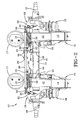
- FIG. 1 Such a prior art semi-trailer steerable lift axle/suspension system having steering dampers and a backup lock mounted on the axle of the system is shown in FIG. 1 .
- Suspension assembly 51 includes a trailing arm-type beam 52 that is pivotally mounted on a hanger 53 in a manner well known in the heavy-duty vehicle suspension art.
- Hanger 53 is mounted on the underside of a trailer frame (not shown) and extends downwardly therefrom.
- Beam 52 is elongated and extends aft or rearwardly from hanger 53, and an axle 54 is captured by U-bolts 55 in cutouts (not shown) formed in the transversely spaced beams 52.
- a shock absorber typically is mounted on and extends between hanger 53 and beam 52 in a manner well known in the art.
- a cantilever extension 56 of beam 52 extends rearwardly beyond axle 54 and supports an air spring 57, which is mounted on and extends between the beam extension and the trailer frame.
- Axle 54 includes a central axle tube 61 ( FIG. 1 ), and a steering assembly 70, which is well known in the heavy-duty vehicle steerable axle/suspension system art, is mounted on each end of axle tube 61 outboardly from beams 52.
- An axle spindle 60 is mounted on each steering assembly 70, in alignment with axle tube 61, and extends outboardly therefrom.
- a brake assembly (not shown) of a type which is commonly known in the heavy-duty vehicle braking art is mounted on and beneath each steering assembly 70.
- a tie rod 71 is operatively connected to and extends between each steering assembly 70.
- a pneumatic lift assembly 72 is mounted on each frame hanger 53 and beam 52 to enable lifting of the entire axle/suspension system 50 when it is advantageous for the vehicle operator to do so, such as when the trailer is carrying less cargo or during operation of the vehicle in the reverse or backup direction.
- each steering damper is operatively connected to steering assembly 70 and further is mounted on axle tube 61 via a bracket 75.
- Backup lock assembly 74 is mounted on tie rod 71 and further is mounted on axle tube 61 via a bracket 76.
- brackets 75 and 76 respectively, must each be welded to axle tube 61, and such attachment of structures on the axle tube can cause various problems.
- axle tube 61 For example, during operation of the vehicle, stress rises occur at the welds (not shown) where brackets 75, 76 are attached to axle tube 61. Thus, a much thicker axle tube 61 is necessary to prevent or minimize axle tube failures caused by such stresses, which adds undesirable weight to the vehicle.
- steering dampers 73 and backup lock assembly 74 on axle 54 typically means that axle manufacturers or trailer builders mounted these components on the axle. Consequently, the axle manufacturer or the trailer builder has to become involved in suspension assembly geometry layout work, and they typically have less than complete familiarity with this design area. Also, if a problem occurs with steering damper 73, backup lock assembly 74, or brackets 75, 76 in prior art steerable lift axle/ suspension system 50, repair or replacement of the components can cause damage to axle tube 61, resulting in the need to replace the entire axle 54. Such repairs are expensive and time consuming due to involving much cutting, welding, and fixturing. Also, in the event such repair or replacement is necessary, the end user may have to look to various suppliers, typically the trailer manufacturer and/or the axle manufacturer, to fix the problem, depending on which manufacturer mounted steering dampers 73 and backup lock assembly 74 on axle 54.
- prior art steerable lift axle/suspension system 50 merely is illustrative of one type of prior art system having steering dampers and a backup lock mounted on the axle, and of the environment in which the steering damper and backup lock beam attachment embodying the present invention, to be described immediately below, can be used. It is understood that steering dampers 73 and backup lock assemblies 74 can be utilized in other heavy-duty vehicle applications besides semi-trailers, such as straight trucks. It also is understood that steering dampers could be utilized on non-lift steerable axle/suspension systems, which would not include a backup lock.
- EP-A-0747281 defining the preamble of claim 1 describes a sell-steering axle in which again the steering dampers have their inboard ends connected to brackets on the axle, adjacent the axles seats that connects to the trailing arm.
- a special feature in EP-A-0747281 is incorporating a backup lock mechanism in the telescopic dampers themselves, operated by a fluid valve.
- US-A-4925165 shows a different approach to positioning a steering stabiliser; a single stabiliser has one end connected to one of the chassis side frame members and the other end connected to an articulation of a steering linkage, part-way across the chassis.
- US 4,010,813 describes a half-axle steering system having balanced elastic chambers attached to a connecting bar between the two steering assemblies to prevent uncontrolled steering movement of the wheels.
- the present invention provides, as set out in claim 1, a steerable axle/suspension system for a vehicle, said system including
- the invention addresses the noted problems by mounting the steering dampers (and optionally a backup lock) on the suspension assembly beams via support brackets rather than on the axle tube.
- the steering dampers and optionally a backup lock
- axle manufacturers heretofore have made the walls of steerable suspension axle tubes thicker, with the undesirable result of adding weight to the vehicle.
- the present invention also enables the suspension manufacturer to be more completely involved in the design of the overall axle/suspension system, which results in improved performance characteristics, more compact design, ease of installation, and reduced weight. It also benefits the end user because the user can turn to one supplier, that is, the suspension manufacturer, rather than many suppliers, including axle and trailer manufacturers, to service the system.
- a desirable location of the component mounting brackets on the inboard side of the suspension beams by bolt attachment is advantageous because, if a problem occurs with the components or brackets, new parts can be obtained and the defective parts easily replaced or repaired.
- problems with the brackets or the mounted components also could cause damage to the axle tube, resulting in the need to replace the entire axle. Such repairs are expensive and time-consuming because they involve much cutting, welding, and fixing.
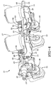
- a steerable lift axle/suspension system embodying the invention is indicated generally at 10 in FIGS. 2-5 . It is understood that the concepts of the present invention can be applied to steerable axle/suspension system types other than those shown in FIG. 2 , such as those having different types of beams and/or backup lock assemblies and/or steering dampers, non-lift steerable axle/suspension systems lacking a backup lock altogether, and steerable axle/suspension systems used on heavy-duty vehicles other than semi-trailers, such as straight trucks, without affecting the overall concept of the present invention, which is directed to the manner of mounting the steering dampers and preferably also a backup lock on the axle/suspension system.
- semi-trailer steerable lift axle/suspension system 10 includes a pair of suspension assemblies 11, only one of which will be described in detail herein, inasmuch as each one of the suspension assemblies is generally identical.
- Suspension assembly 11 includes a trailing arm-type elongated beam 12 that is pivotally mounted on a hanger 13 in a manner well known in the heavy-duty vehicle suspension art.
- Hanger 13 in turn, is mounted on the underside of a trailer frame (not shown) and extends downwardly therefrom.
- Beam 12 extends rearwardly or aft from hanger 13, and an axle 14 passes through and is captured in openings 31 ( FIG. 5 ) formed in the transversely spaced beams.
- a shock absorber 15 is mounted on and extends between hanger 13 and beam 12 in a usual manner.
- a cantilever extension 16 of beam 12 extends aft or rearwardly beyond axle 14 and supports an air spring 17 which is mounted on and extends between the beam extension and the trailer frame.
- Axle 14 includes a central axle tube 41, and a steering assembly 19, which is well known in the heavy-duty vehicle steerable axle/suspension system art, is mounted on each end of axle tube 41 outboardly from beams 12.
- An axle spindle 40 is mounted on each steering assembly 19, in alignment with axle tube 41, and extends outboardly therefrom ( FIGS. 2 and 5 ).
- a brake assembly 18 of a type which is well known in the heavy-duty vehicle braking art is mounted on and beneath each steering assembly 19.
- a tie rod 20 is operatively connected to and extends between each steering assembly 19.
- a pneumatic lift assembly 21 is mounted on frame hanger 13 and beam 12 to enable lifting of the entire axle/suspension system 10 when it is advantageous for the vehicle operator to do so, such as when the trailer is carrying less cargo or during operation of the vehicle in the reverse or "backup" direction.
- steering dampers 22 and backup lock assembly 23 traditionally have been mounted on axle tube 41 via some type of attachment or bracket that is welded to the tube, with the adverse consequences of such axle mounting having been described in detail hereinabove.
- a first bracket 24 is configured for attachment of the driver's side steering damper 22 and backup lock assembly 23 to driver's side beam 12. More particularly, first bracket 24 is mounted directly on the inboard sidewall of driver's side beam 12 using fasteners such as bolts 25 ( FIG. 3 ).
- a second bracket 34 configured for attachment of the curbside steering damper 22 similarly is attached to the curbside beam 12 via fasteners such as bolts 37 ( FIG. 4 ).
- Each steering damper 22, in turn, is mounted at its outboard end to its respective steering assembly 19 and at its inboard end to its respective bracket 24, 34, by usual fastening means such as bolts 32, 33, respectively.
- backup lock assembly 23 also is mounted on driver's side first bracket 24 via usual fastening means such as bolts (not shown).
- a spacer 39 is disposed between each bracket 24, 34 and axle tube 41 ( FIG. 5 ), and a pair of U-bolts 38 are placed about the axle tube.
- Each U-bolt 38 is aligned with a respective one of brackets 24, 34 and its respective spacer 39, and secured to the bracket in a usual manner.
- Each U-bolt 38 is tightened sufficiently to capture spacer 39 between its respective bracket 24, 34 and axle tube 41. This arrangement of parts minimizes unwanted movement or shimmy of brackets 24, 34 during operation of the vehicle.
- U-bolts 38 and spacers 39 are not welded on axle tube 41, but merely abut the tube. Since no structure such as brackets 75, 76 shown in prior art FIG. 1 are welded on axle tube 41, the tube used can have a thinner wall thickness than is required in many prior art designs such as axle tube 61 of FIG. 1 .
- prior art axle tube 61 might have a wall thickness of about 24 mm (about 15/16 of an inch), while axle tube 41, useful in the present invention, might have a wall thickness of only about 17.5 mm (11/16 of an inch).
- a shock absorber component 35 of each steering damper 22 which is similar to a typical shock absorber, functions to minimize side-to-side shimmy of the vehicle wheels (not shown) mounted on the end of each axle spindle 40 during over-the-road operation of the vehicle.
- Coil spring component 36 of damper 22 is disposed about shock absorber component 35 and is biased in the outboard direction to cause steering assembly 19 to generally align axle spindles 40 with axle tube 41 and maintain the wheels in a fore-aft straightened condition in a manner well known in the art whenever axle/suspension system 10 is raised to a lifted position by pneumatic lift assemblies 21 and the vehicle is traveling over-the-road.
- Such alignment minimizes unwanted drag on the vehicle, which can result in increased fuel costs and the like.
- Backup lock assembly 23 is utilized when axle/suspension system 10 is in the lifted position and the vehicle is backing up or moving in reverse. More particularly, a coil return spring 26 ( FIG. 3 ) of assembly 23 is biased to maintain a lock 27 in its downwardmost and unlocked position which in turn allows tie rod 20 to move freely from side-to-side when steering assemblies 19 pivot during forward vehicle operation. However, when axle/suspension system 10 is in the lifted or raised position and the vehicle is backing up or moving in reverse, it is desirable to lock tie rod 20 and attached steering assemblies 19. Thus, a bracket 28 is mounted on tie rod 20 adjacent to lock 27 by any suitable means such as bolts 44, and is formed with a slot 29 for positive locking engagement with lock 27.
- Locking slot 29 is located relative to lock 27 so that when they are engaged, axle spindles 40 generally are aligned with axle tube 41 and the wheels are straight in the fore-aft direction, thus minimizing the possibility that the vehicle wheels will be turned during backing up of the vehicle which can cause vehicle handling problems.
- a pneumatic air bag 30 ( FIG. 3 ) is filled with compressed air (not shown), and pivots lock 27 upwardly into slot 29 against the bias of spring 26 to lock steering assemblies 19 in place in the straightened position shown in Figs. 2 through 5 .
- This design of pivoting lock 27 and actuating pneumatic bag 30 also is novel in that the bag, which is a small automotive-type air actuator, overcomes the bias of small coil return spring 26 to actuate the lock to engage tie rod bracket 28 in slot 29, and when the air bag is defeated, spring 26 moves to its biased position to unlock assembly 23.
- bracket 24 for mounting a steering damper 22 and backup lock assembly 23 could be mounted on curbside beam 12 and that bracket 34 for mounting only a steering damper 22 could be mounted on driver's side beam 12, without affecting the overall concept.
- the present steerable lift axle/suspension system could be utilized in heavy-duty vehicle applications other than semi-trailers, such as on straight trucks.
- the concepts herein also could be applied to non-lift steerable axle/suspension systems, which do not include a backup lock, for mounting steering dampers at a location other than the axle.
- the present invention can be utilized on various types of steerable axle/suspension systems having various styles of beams, including leading arm, trailing arm, top mount, and bottom mount, without affecting the overall concept of the invention.
- the concepts of the present invention could be applied to steering dampers, backup lock assemblies, and axle-centering devices other than dampers 22 and backup lock assembly 23 shown in FIGS. 2-5 .
- the described steering damper and backup lock beam attachment for steerable lift axle/suspension systems achieves various objectives not heretofore seen in prior art steerable axle/suspension systems, including providing an alternative mounting location for the steering dampers and the backup lock assembly of the system, thereby eliminating the possibility of axle tube failures caused by the stresses of an axle mounting location commonly seen in prior art systems, and enabling use of thinner walled and therefore lighter axle tubes. It also enables suspension manufacturers to design the overall axle/suspension system which, in turn, enables end users of the steerable axle/suspension systems to utilize a single supplier for servicing the system.
- this steerable axle/suspension system provides a durable and cost effective alternative to prior art steerable axle/suspension systems which mount the steering dampers and backup lock assembly on the axle.
Landscapes
- Engineering & Computer Science (AREA)
- Mechanical Engineering (AREA)
- Chemical & Material Sciences (AREA)
- Combustion & Propulsion (AREA)
- Transportation (AREA)
- Vehicle Body Suspensions (AREA)
- Vibration Prevention Devices (AREA)
Claims (10)
- Lenkbares Achs- und Aufhängungssystem für ein Fahrzeug, wobei das System Folgendes umfasst:ein Paar transversal beabstandete Aufhängungsanordnungen (11), von denen jede einen sich in Längsrichtung erstreckenden Längs-Träger (12), wobei ein erstes Ende desselben ausgebildet ist, um an einem Rahmen des Fahrzeuges angebracht zu werden, um im Wesentlichen eine Schwenkbewegung des Trägers (12) zu ermöglichen, und eine Luftfeder (17) umfasst, die an einem zweiten Ende des Trägers (12) und dem Rahmen angebracht ist und sich zwischen diesen erstreckt,eine Achse (14), Folgendes umfassend:- einen zentralen Rohrabschnitt (41), der sich zwischen den Trägern (12) erstreckt und dessen Enden von den Trägern (12) festgehalten sind;- ein Paar von Lenkbaugruppen (19), die an den Achsen-Rohrenden befestigt sind, wobei sich jede Lenkbaugruppe (19) von dem jeweiligen Träger (12) weg nach außen erstreckt;- jeweilige Achsschenkel (40), die an den Lenkbaugruppen (19) befestigt sind und sich von diesen weg nach außen erstrecken, wobei die Lenkbaugruppen (19) wirksam mit jeweiligen Enden einer sich transversal erstreckenden Spurstange (20) verbunden sind;ein Paar von Lenkungsdämpfern (22), die jeweils ein sich nach außen erstreckendes Ende, das mit einer jeweiligen der Lenkbaugruppen (19) wirksam verbunden ist, und ein sich nach innen erstreckendes Ende aufweisen;dadurch gekennzeichnet, dass das sich nach innen erstreckende Ende jedes Lenkungsdämpfers (22) auf einer Auflage (24, 34) befestigt ist, die auf dem jeweiligen schwenkbaren Träger (12) befestigt ist.
- System nach Anspruch 1, worin jeder der Lenkungsdämpfer (22) eine Schraubenfeder (36), die nach außen hin vorgespannt ist und auf die jeweilige Lenkbaugruppe (19) wirkt, um den entsprechenden Achsschenkel (40) in fluchtender Ausrichtung mit dem zentralen Achsenrohr (41) zu drücken, und eine Lenkungsdämpfer-Stoßdämpferkomponente (35) umfasst.
- System nach Anspruch 1 oder 2, worin jede der Auflagen (24, 34), auf welcher ein Lenkungsdämpfer (22) befestigt ist, in Bezug auf das benachbarte Achsenrohr (41) mithilfe eines jeweiligen U-Bolzens (38), der an der Auflage (24, 34) fixiert ist und sich um das Achsenrohr (41) erstreckt, stabilisiert ist, wobei ein jeweiliges Abstandselement (39), das mit dem U-Bolzen (38) fluchtend ausgerichtet ist, an die Auflage (24, 34) und das Achsenrohr (41) anstoßend angeordnet und zwischen diesen festgehalten ist.
- System nach einem der vorangegangenen Ansprüche, worin die Auflagen (24, 34) durch Bolzen (25, 37) an einer sich nach innen erstreckenden Seitenwand des jeweiligen schwenkbaren Trägers (12) befestigt sind.
- System nach einem der vorangegangenen Ansprüche, worin das erste Ende jedes Trägers (12) schwenkbar an einem Aufhänger (13) befestigt ist, der am Fahrzeugrahmen befestigt ist und von diesem nach unten wegsteht.
- System nach Anspruch 5, worin die Träger (12) Längslenkerträger sind.
- System nach Anspruch 5 oder 6, worin zwischen jedem der Aufhänger (13) und ihren jeweiligen Trägern (12) ein Aufhängungsstoßdämpfer (15) befestigt ist.
- System nach einem der vorangegangenen Ansprüche, worin eine Bremsanordnung (18) auf und unterhalb jeder der Lenkbaugruppen (19) befestigt ist.
- System nach einem der vorangegangenen Ansprüche, worin jede der Aufhängungsanordnungen (11) eine Druckluft-Hebeanordnung (21) zum Anheben der Achse (14) und der Träger (12) auf eine angehobene Position sowie eine Rückfahrsperranordnung (23) umfasst, die auf einer der Trägerauflagen (24) befestigt ist, um die Spurstange (20) in einer vorbestimmten Transversalposition zu sperren und dadurch mithilfe der Lenkbaugruppen (19) die Achsschenkel (40) im Wesentlichen mit dem Achsenrohr (41) fluchtend ausgerichtet zu halten, wenn das Fahrzeug rückwärts fährt und wenn sich das Achsen/Aufhängungssystem (10) in angehobener Position befindet.
- System nach Anspruch 9, worin eine Auflage (28) mit einem Arretierschlitz (29) auf der Spurstange (20) befestigt ist, wobei ein Sperrelement (27) auf der einen der Trägerauflagen (24) befestigt ist, wobei das Sperrelement (27) durch eine Schraubenfeder (26) in eine entsperrte Position hin vorgespannt ist, wenn ein Luftkissen (30) der Rückfahr-Sperranordnung (23), das auf der Trägerauflage (30) befestigt ist, entleert wird, und durch Aufblasen des Luftkissens (30) mit Druckluft die Federvorspannung überwunden wird und das Sperrelement (27) mit dem Arretierschlitz (29) in Eingriff gelangt.
Applications Claiming Priority (3)
| Application Number | Priority Date | Filing Date | Title |
|---|---|---|---|
| US42246402P | 2002-10-30 | 2002-10-30 | |
| US422464P | 2002-10-30 | ||
| PCT/US2003/032281 WO2004041620A1 (en) | 2002-10-30 | 2003-10-10 | Steering damper and backup lock beam attachment |
Publications (3)
| Publication Number | Publication Date |
|---|---|
| EP1556271A1 EP1556271A1 (de) | 2005-07-27 |
| EP1556271B1 true EP1556271B1 (de) | 2009-03-25 |
| EP1556271B8 EP1556271B8 (de) | 2009-06-10 |
Family
ID=32312511
Family Applications (1)
| Application Number | Title | Priority Date | Filing Date |
|---|---|---|---|
| EP03810775A Expired - Lifetime EP1556271B8 (de) | 2002-10-30 | 2003-10-10 | Befestigung von lenkungsdämpfer und rückwärtsfahrtverriegelung am träger |
Country Status (10)
| Country | Link |
|---|---|
| US (1) | US7131652B2 (de) |
| EP (1) | EP1556271B8 (de) |
| AT (1) | ATE426544T1 (de) |
| AU (1) | AU2003277354B2 (de) |
| BR (1) | BR0314744B1 (de) |
| CA (1) | CA2499079C (de) |
| DE (1) | DE60326870D1 (de) |
| MX (1) | MXPA05004216A (de) |
| NZ (1) | NZ538600A (de) |
| WO (1) | WO2004041620A1 (de) |
Cited By (1)
| Publication number | Priority date | Publication date | Assignee | Title |
|---|---|---|---|---|
| DE102015104782A1 (de) * | 2015-03-27 | 2016-09-29 | Saf-Holland Gmbh | Achseinheit |
Families Citing this family (23)
| Publication number | Priority date | Publication date | Assignee | Title |
|---|---|---|---|---|
| US7739202B2 (en) * | 2003-04-22 | 2010-06-15 | United Parcel Service Of America, Inc. | Computer system for routing package deliveries |
| US7445220B2 (en) | 2004-02-06 | 2008-11-04 | Daimler Trucks North America Llc | Vehicle axle apparatus |
| US7281721B2 (en) * | 2004-12-03 | 2007-10-16 | Watson & Chalin Manufacturing, Inc. | Suspension system for dump truck/paver truck hitch |
| US20060158023A1 (en) * | 2005-01-14 | 2006-07-20 | The Boler Company | Continuous radius axle and fabricated spindle assembly |
| US20060244236A1 (en) | 2005-04-27 | 2006-11-02 | Cortez Jerome L | Vehicle suspensions having leaf springs and alternative clamp groups |
| US8029008B2 (en) * | 2005-04-27 | 2011-10-04 | Hendrickson Usa, L.L.C. | Vehicle suspensions having leaf springs and alternative clamp groups |
| FR2905108A1 (fr) * | 2006-08-25 | 2008-02-29 | Jacques Delaplace | Ensemble roulant auto-suiveur pour vehicule |
| US7690660B2 (en) * | 2007-03-29 | 2010-04-06 | Hendrickson Usa, L.L.C. | Leading and trailing arm suspensions having a fully integrated arm |
| US7748726B2 (en) | 2007-04-12 | 2010-07-06 | Hendrickson Usa, L.L.C. | Leading and trailing arm suspensions with z-shaped arms |
| US7938416B2 (en) * | 2008-04-18 | 2011-05-10 | Lbc Contracting, Ltd. | Air suspension adapter kit |
| US7845659B2 (en) * | 2008-12-02 | 2010-12-07 | Watson & Chalin Manufacturing, Inc. | Dump truck tag axle suspension control |
| US8544867B1 (en) | 2011-01-03 | 2013-10-01 | Perkins Motor Transport Inc. | Tow bar balance system |
| US8616565B1 (en) | 2012-09-06 | 2013-12-31 | Watson & Chalin Manufacturing, Inc. | Self-steer lift axle suspension system having a steering return, damper and lock integrated with a steering knuckle assembly |
| BR102013010210A2 (pt) * | 2013-04-26 | 2015-06-23 | Luis Carlos Fanti | Eixo autodirecional independente para semirreboque com elevador pneumático |
| DE102013107938A1 (de) * | 2013-07-25 | 2015-01-29 | Bpw Bergische Achsen Kg | Lenkachse, vorzugsweise Nachlauf-Lenkachse |
| US10427738B2 (en) | 2015-06-18 | 2019-10-01 | Volvo Truck Corporation | Liftable axle suspension |
| US9718507B2 (en) * | 2015-10-29 | 2017-08-01 | Cnh Industrial America Llc | Method of steering a weight transfer axle on a combine |
| CN109789893B (zh) | 2016-10-04 | 2021-08-03 | 亨德里克森美国有限责任公司 | 用于可转向重型车辆车轴/悬架系统的转向定中/阻尼机构 |
| US10293875B2 (en) * | 2017-01-25 | 2019-05-21 | Consolidated Metco, Inc. | Axel lift mechanism |
| US10967927B2 (en) | 2017-09-22 | 2021-04-06 | Link Mfg., Ltd. | Mounting brackets for auxiliary suspension systems |
| US11225287B1 (en) * | 2020-07-14 | 2022-01-18 | Arvinmeritor Technology, Llc | Axle system having an axle lift kit and method of assembly |
| WO2023283464A1 (en) * | 2021-07-08 | 2023-01-12 | Link Mfg., Ltd. | Driven lift axles and associated systems and methods |
| WO2023168538A1 (en) * | 2022-03-11 | 2023-09-14 | Gn Technologies Inc. | Vehicle steering wheels system |
Family Cites Families (11)
| Publication number | Priority date | Publication date | Assignee | Title |
|---|---|---|---|---|
| AT282366B (de) | 1967-02-20 | 1970-06-25 | Roman Franz Sauer | Rückfahrlenksperre, insbesondere für die selbsteinspurende Achseinheit eines Sattelanhängers |
| US4010813A (en) | 1976-03-10 | 1977-03-08 | Andre Quigniot | Leading link type independent systems |
| FR2335359A1 (fr) * | 1975-12-17 | 1977-07-15 | Fruehauf France | Essieu orientable pour vehicule routier |
| US4506910A (en) * | 1982-09-21 | 1985-03-26 | Granning Suspensions, Inc. | Automotive vehicle suspension |
| US4925165A (en) | 1988-01-29 | 1990-05-15 | Sketo James L | Steering stabilizer |
| DE3815033C1 (de) * | 1988-05-03 | 1989-07-06 | Deutsche Gesellschaft Fuer Wiederaufarbeitung Von Kernbrennstoffen Mbh, 3000 Hannover, De | |
| AU666572B2 (en) * | 1992-10-19 | 1996-02-15 | Hendrickson International Corporation | Axle suspension systems |
| US5620194A (en) | 1995-06-07 | 1997-04-15 | The Boler Company | Self-steering suspension lockout mechanism |
| CA2240791A1 (en) * | 1997-07-16 | 1999-01-16 | Neway Anchorlok International, Inc | Trailing arm suspension |
| US6007078A (en) * | 1998-03-31 | 1999-12-28 | The Boler Company. | Self-steering, caster adjustable suspension system |
| US6957819B2 (en) * | 2003-06-20 | 2005-10-25 | Watson & Chalin Manufacturing, Inc. | Lift axle parallelogram suspension system |
-
2003
- 2003-10-10 EP EP03810775A patent/EP1556271B8/de not_active Expired - Lifetime
- 2003-10-10 US US10/683,634 patent/US7131652B2/en not_active Expired - Lifetime
- 2003-10-10 AU AU2003277354A patent/AU2003277354B2/en not_active Ceased
- 2003-10-10 NZ NZ538600A patent/NZ538600A/en not_active IP Right Cessation
- 2003-10-10 CA CA002499079A patent/CA2499079C/en not_active Expired - Lifetime
- 2003-10-10 WO PCT/US2003/032281 patent/WO2004041620A1/en not_active Ceased
- 2003-10-10 BR BRPI0314744-4A patent/BR0314744B1/pt active IP Right Grant
- 2003-10-10 AT AT03810775T patent/ATE426544T1/de active
- 2003-10-10 MX MXPA05004216A patent/MXPA05004216A/es active IP Right Grant
- 2003-10-10 DE DE60326870T patent/DE60326870D1/de not_active Expired - Lifetime
Cited By (2)
| Publication number | Priority date | Publication date | Assignee | Title |
|---|---|---|---|---|
| DE102015104782A1 (de) * | 2015-03-27 | 2016-09-29 | Saf-Holland Gmbh | Achseinheit |
| DE102015104782B4 (de) | 2015-03-27 | 2019-07-18 | Saf-Holland Gmbh | Achseinheit |
Also Published As
| Publication number | Publication date |
|---|---|
| AU2003277354A1 (en) | 2004-06-07 |
| CA2499079A1 (en) | 2004-05-21 |
| EP1556271A1 (de) | 2005-07-27 |
| US20040084866A1 (en) | 2004-05-06 |
| CA2499079C (en) | 2008-12-09 |
| WO2004041620A1 (en) | 2004-05-21 |
| NZ538600A (en) | 2007-10-26 |
| DE60326870D1 (de) | 2009-05-07 |
| US7131652B2 (en) | 2006-11-07 |
| AU2003277354B2 (en) | 2007-10-11 |
| MXPA05004216A (es) | 2005-06-08 |
| BR0314744B1 (pt) | 2012-09-04 |
| BR0314744A (pt) | 2005-07-26 |
| ATE426544T1 (de) | 2009-04-15 |
| EP1556271B8 (de) | 2009-06-10 |
Similar Documents
| Publication | Publication Date | Title |
|---|---|---|
| EP1556271B1 (de) | Befestigung von lenkungsdämpfer und rückwärtsfahrtverriegelung am träger | |
| CA2108724C (en) | Axle suspension system | |
| US5150918A (en) | Trailing arm suspension for vehicle | |
| EP1202900B1 (de) | Achsanhebevorrichtung unter fahrzeugrahmen | |
| CN114802439B (zh) | 自转向车桥的转向节 | |
| US5988672A (en) | Suspension system with integral box beam | |
| US5791681A (en) | Single beam suspension system | |
| EP3844004B1 (de) | Achskörperverbindung für schwerlastfahrzeuge | |
| US10471988B2 (en) | Steering centering/damping mechanism for a steerable heavy-duty vehicle axle/suspension system | |
| JP3487213B2 (ja) | 車両のサブフレーム構造 | |
| US12179536B2 (en) | Under beam lift assembly for heavy-duty vehicles | |
| WO1998030404A1 (en) | Tandem rear axle suspensions for trucks and truck-tractors | |
| US12391082B2 (en) | Axle-to-beam connection for heavy-duty vehicle axle/suspension systems | |
| US20210101461A1 (en) | Shroud for a heavy-duty vehicle component | |
| WO2021066826A1 (en) | Shroud for a heavy-duty vehicle component | |
| NZ260280A (en) | Vehicle axle rigidly attached to swing beam by passing through beam side walls so as to minimise distortion of axle cross-section | |
| JPH0796731A (ja) | 自動車のスタビライザバー取付装置 | |
| JPH0532014U (ja) | エアサスペンシヨン装置 |
Legal Events
| Date | Code | Title | Description |
|---|---|---|---|
| PUAI | Public reference made under article 153(3) epc to a published international application that has entered the european phase |
Free format text: ORIGINAL CODE: 0009012 |
|
| 17P | Request for examination filed |
Effective date: 20050406 |
|
| AK | Designated contracting states |
Kind code of ref document: A1 Designated state(s): AT BE BG CH CY CZ DE DK EE ES FI FR GB GR HU IE IT LI LU MC NL PT RO SE SI SK TR |
|
| AX | Request for extension of the european patent |
Extension state: AL LT LV MK |
|
| RAP1 | Party data changed (applicant data changed or rights of an application transferred) |
Owner name: HENDRICKSON INTERNATIONAL CORPORATION |
|
| DAX | Request for extension of the european patent (deleted) | ||
| 17Q | First examination report despatched |
Effective date: 20051102 |
|
| GRAP | Despatch of communication of intention to grant a patent |
Free format text: ORIGINAL CODE: EPIDOSNIGR1 |
|
| GRAS | Grant fee paid |
Free format text: ORIGINAL CODE: EPIDOSNIGR3 |
|
| GRAA | (expected) grant |
Free format text: ORIGINAL CODE: 0009210 |
|
| AK | Designated contracting states |
Kind code of ref document: B1 Designated state(s): AT BE BG CH CY CZ DE DK EE ES FI FR GB GR HU IE IT LI LU MC NL PT RO SE SI SK TR |
|
| REG | Reference to a national code |
Ref country code: GB Ref legal event code: FG4D |
|
| RBV | Designated contracting states (corrected) |
Designated state(s): DE |
|
| REG | Reference to a national code |
Ref country code: IE Ref legal event code: FG4D |
|
| REF | Corresponds to: |
Ref document number: 60326870 Country of ref document: DE Date of ref document: 20090507 Kind code of ref document: P |
|
| PLBE | No opposition filed within time limit |
Free format text: ORIGINAL CODE: 0009261 |
|
| STAA | Information on the status of an ep patent application or granted ep patent |
Free format text: STATUS: NO OPPOSITION FILED WITHIN TIME LIMIT |
|
| 26N | No opposition filed |
Effective date: 20091229 |
|
| REG | Reference to a national code |
Ref country code: IE Ref legal event code: MM4A |
|
| REG | Reference to a national code |
Ref country code: FR Ref legal event code: ST Effective date: 20100630 |
|
| PGFP | Annual fee paid to national office [announced via postgrant information from national office to epo] |
Ref country code: DE Payment date: 20191029 Year of fee payment: 17 |
|
| REG | Reference to a national code |
Ref country code: DE Ref legal event code: R082 Ref document number: 60326870 Country of ref document: DE Representative=s name: MEWBURN ELLIS LLP, DE Ref country code: DE Ref legal event code: R081 Ref document number: 60326870 Country of ref document: DE Owner name: HENDRICKSON INTERNATIONAL CORP., SCHAUMBURG, US Free format text: FORMER OWNER: HENDRICKSON INTERNATIONAL CORP., ITASCA, ILL., US |
|
| REG | Reference to a national code |
Ref country code: DE Ref legal event code: R119 Ref document number: 60326870 Country of ref document: DE |
|
| PG25 | Lapsed in a contracting state [announced via postgrant information from national office to epo] |
Ref country code: DE Free format text: LAPSE BECAUSE OF NON-PAYMENT OF DUE FEES Effective date: 20210501 |