EP1555702A2 - Film-covered electric device having pressure release opening - Google Patents
Film-covered electric device having pressure release opening Download PDFInfo
- Publication number
- EP1555702A2 EP1555702A2 EP05090003A EP05090003A EP1555702A2 EP 1555702 A2 EP1555702 A2 EP 1555702A2 EP 05090003 A EP05090003 A EP 05090003A EP 05090003 A EP05090003 A EP 05090003A EP 1555702 A2 EP1555702 A2 EP 1555702A2
- Authority
- EP
- European Patent Office
- Prior art keywords
- electric device
- film
- receiving part
- unfused
- device element
- Prior art date
- Legal status (The legal status is an assumption and is not a legal conclusion. Google has not performed a legal analysis and makes no representation as to the accuracy of the status listed.)
- Granted
Links
Images


Classifications
-
- H—ELECTRICITY
- H01—ELECTRIC ELEMENTS
- H01M—PROCESSES OR MEANS, e.g. BATTERIES, FOR THE DIRECT CONVERSION OF CHEMICAL ENERGY INTO ELECTRICAL ENERGY
- H01M50/00—Constructional details or processes of manufacture of the non-active parts of electrochemical cells other than fuel cells, e.g. hybrid cells
- H01M50/10—Primary casings; Jackets or wrappings
- H01M50/183—Sealing members
-
- H—ELECTRICITY
- H01—ELECTRIC ELEMENTS
- H01G—CAPACITORS; CAPACITORS, RECTIFIERS, DETECTORS, SWITCHING DEVICES, LIGHT-SENSITIVE OR TEMPERATURE-SENSITIVE DEVICES OF THE ELECTROLYTIC TYPE
- H01G9/00—Electrolytic capacitors, rectifiers, detectors, switching devices, light-sensitive or temperature-sensitive devices; Processes of their manufacture
- H01G9/004—Details
- H01G9/08—Housing; Encapsulation
-
- H—ELECTRICITY
- H01—ELECTRIC ELEMENTS
- H01M—PROCESSES OR MEANS, e.g. BATTERIES, FOR THE DIRECT CONVERSION OF CHEMICAL ENERGY INTO ELECTRICAL ENERGY
- H01M50/00—Constructional details or processes of manufacture of the non-active parts of electrochemical cells other than fuel cells, e.g. hybrid cells
- H01M50/10—Primary casings; Jackets or wrappings
- H01M50/116—Primary casings; Jackets or wrappings characterised by the material
- H01M50/117—Inorganic material
- H01M50/119—Metals
-
- H—ELECTRICITY
- H01—ELECTRIC ELEMENTS
- H01M—PROCESSES OR MEANS, e.g. BATTERIES, FOR THE DIRECT CONVERSION OF CHEMICAL ENERGY INTO ELECTRICAL ENERGY
- H01M50/00—Constructional details or processes of manufacture of the non-active parts of electrochemical cells other than fuel cells, e.g. hybrid cells
- H01M50/10—Primary casings; Jackets or wrappings
- H01M50/116—Primary casings; Jackets or wrappings characterised by the material
- H01M50/121—Organic material
-
- H—ELECTRICITY
- H01—ELECTRIC ELEMENTS
- H01M—PROCESSES OR MEANS, e.g. BATTERIES, FOR THE DIRECT CONVERSION OF CHEMICAL ENERGY INTO ELECTRICAL ENERGY
- H01M50/00—Constructional details or processes of manufacture of the non-active parts of electrochemical cells other than fuel cells, e.g. hybrid cells
- H01M50/10—Primary casings; Jackets or wrappings
- H01M50/116—Primary casings; Jackets or wrappings characterised by the material
- H01M50/124—Primary casings; Jackets or wrappings characterised by the material having a layered structure
- H01M50/126—Primary casings; Jackets or wrappings characterised by the material having a layered structure comprising three or more layers
- H01M50/129—Primary casings; Jackets or wrappings characterised by the material having a layered structure comprising three or more layers with two or more layers of only organic material
-
- H—ELECTRICITY
- H01—ELECTRIC ELEMENTS
- H01M—PROCESSES OR MEANS, e.g. BATTERIES, FOR THE DIRECT CONVERSION OF CHEMICAL ENERGY INTO ELECTRICAL ENERGY
- H01M50/00—Constructional details or processes of manufacture of the non-active parts of electrochemical cells other than fuel cells, e.g. hybrid cells
- H01M50/10—Primary casings; Jackets or wrappings
- H01M50/131—Primary casings; Jackets or wrappings characterised by physical properties, e.g. gas permeability, size or heat resistance
- H01M50/133—Thickness
-
- H—ELECTRICITY
- H01—ELECTRIC ELEMENTS
- H01M—PROCESSES OR MEANS, e.g. BATTERIES, FOR THE DIRECT CONVERSION OF CHEMICAL ENERGY INTO ELECTRICAL ENERGY
- H01M50/00—Constructional details or processes of manufacture of the non-active parts of electrochemical cells other than fuel cells, e.g. hybrid cells
- H01M50/10—Primary casings; Jackets or wrappings
- H01M50/131—Primary casings; Jackets or wrappings characterised by physical properties, e.g. gas permeability, size or heat resistance
- H01M50/136—Flexibility or foldability
-
- H—ELECTRICITY
- H01—ELECTRIC ELEMENTS
- H01M—PROCESSES OR MEANS, e.g. BATTERIES, FOR THE DIRECT CONVERSION OF CHEMICAL ENERGY INTO ELECTRICAL ENERGY
- H01M50/00—Constructional details or processes of manufacture of the non-active parts of electrochemical cells other than fuel cells, e.g. hybrid cells
- H01M50/20—Mountings; Secondary casings or frames; Racks, modules or packs; Suspension devices; Shock absorbers; Transport or carrying devices; Holders
-
- H—ELECTRICITY
- H01—ELECTRIC ELEMENTS
- H01M—PROCESSES OR MEANS, e.g. BATTERIES, FOR THE DIRECT CONVERSION OF CHEMICAL ENERGY INTO ELECTRICAL ENERGY
- H01M50/00—Constructional details or processes of manufacture of the non-active parts of electrochemical cells other than fuel cells, e.g. hybrid cells
- H01M50/30—Arrangements for facilitating escape of gases
-
- Y—GENERAL TAGGING OF NEW TECHNOLOGICAL DEVELOPMENTS; GENERAL TAGGING OF CROSS-SECTIONAL TECHNOLOGIES SPANNING OVER SEVERAL SECTIONS OF THE IPC; TECHNICAL SUBJECTS COVERED BY FORMER USPC CROSS-REFERENCE ART COLLECTIONS [XRACs] AND DIGESTS
- Y02—TECHNOLOGIES OR APPLICATIONS FOR MITIGATION OR ADAPTATION AGAINST CLIMATE CHANGE
- Y02E—REDUCTION OF GREENHOUSE GAS [GHG] EMISSIONS, RELATED TO ENERGY GENERATION, TRANSMISSION OR DISTRIBUTION
- Y02E60/00—Enabling technologies; Technologies with a potential or indirect contribution to GHG emissions mitigation
- Y02E60/10—Energy storage using batteries
-
- Y—GENERAL TAGGING OF NEW TECHNOLOGICAL DEVELOPMENTS; GENERAL TAGGING OF CROSS-SECTIONAL TECHNOLOGIES SPANNING OVER SEVERAL SECTIONS OF THE IPC; TECHNICAL SUBJECTS COVERED BY FORMER USPC CROSS-REFERENCE ART COLLECTIONS [XRACs] AND DIGESTS
- Y02—TECHNOLOGIES OR APPLICATIONS FOR MITIGATION OR ADAPTATION AGAINST CLIMATE CHANGE
- Y02E—REDUCTION OF GREENHOUSE GAS [GHG] EMISSIONS, RELATED TO ENERGY GENERATION, TRANSMISSION OR DISTRIBUTION
- Y02E60/00—Enabling technologies; Technologies with a potential or indirect contribution to GHG emissions mitigation
- Y02E60/13—Energy storage using capacitors
-
- Y—GENERAL TAGGING OF NEW TECHNOLOGICAL DEVELOPMENTS; GENERAL TAGGING OF CROSS-SECTIONAL TECHNOLOGIES SPANNING OVER SEVERAL SECTIONS OF THE IPC; TECHNICAL SUBJECTS COVERED BY FORMER USPC CROSS-REFERENCE ART COLLECTIONS [XRACs] AND DIGESTS
- Y10—TECHNICAL SUBJECTS COVERED BY FORMER USPC
- Y10T—TECHNICAL SUBJECTS COVERED BY FORMER US CLASSIFICATION
- Y10T428/00—Stock material or miscellaneous articles
- Y10T428/23—Sheet including cover or casing
- Y10T428/239—Complete cover or casing
Definitions
- the present invention relates to a film-covered electric device in which casing films encapsulate therein an electric device element, such as a battery and a capacitor.
- the laminated film includes a metallic thin film layer or metallic foil and thermo-fusing resin film layers.
- the laminated film structure used in the battery casing typically includes a thermo-fusing resin film as a heat-sealing layer laminated on one side of metallic thin film made of aluminum, and a protection film laminated on the other side.
- a battery element In the film-covered battery using the laminated film as a casing, a battery element,generally including a positive electrode, a negative electrode and an electrolyte, is enclosed by the casing so that the thermo-fusing resin film can face inwardly each other, and the casing is thermally fused at the periphery of the battery element to form airtight sealing structure (hereinafter simply referred to as "sealing").
- the battery element has positive and negative electrode leads connected with the positive and negative electrodes, respectively, for drawing them outside the casing. When sealing the battery element, these electrode leads protrude from the casing, and then the casing is thermally fused.
- a voltage over a rated range is applied to a battery during use of the battery, electrolytic solution is possible to be electrolyzed to generate gas, and the rise of pressure inside the battery results.
- electrolysis of electrolyte base or the like also causes to produce gas generating substance.
- the use of a battery within the rated range is basically ideal for preventing gas generation. However, if failure of a control circuit for the battery occurs due to some causes, and a resultant abnormal voltage is applied or surrounding temperature abnormally rises, large quantities of gas may be possibly generated.
- the gas generation inside the battery causes the pressure inside the battery to be raised. Extreme rise of the inside pressure is possible to cause the battery to be exploded if worst comes to worst.
- the battery using a metal can as the casing generally has a pressure relief valve for releasing the gas outside the battery when the pressure inside the battery goes up.
- the film-covered battery, which uses the casing films is difficult to adopt a pressure relief valve because of its structure. When the inside pressure excessively goes up in the film-covered battery, the casing films expand, and finally explodes to eject the gas from a broken position, which is possible to affect surrounding equipment according to the broken position, because it is difficult to determine the position of breaking.
- Japanese Laid-Open Patent Publication No. 2000-100399 discloses a film-covered battery in which a battery element is sealed under a condition that a part of thermally fused portion is set to lower temperature than the other part.
- Japanese Laid-Open Patent Publication No. 11-97070 discloses another film-covered battery in which a part of thermally fused portion has been made with thermally non-fusible resin sheet intervened. In both examples, a part of the casing has been made with lower thermo-fusing strength of films, the part acting as a safety valve.
- Japanese Laid-Open Patent Publication No. 2002-56835 discloses a structure in which a part of thermally fused portion is cut off from outside.
- Japanese Laid-Open Patent Publication No. 10-55792 discloses another structure in which a part of a sealed side has an un-bonded portion that becomes smaller in width outward from the inside of the battery.
- Each of these structures has on the thermally fused portion a part where the width of the fused portion partially becomes narrower outward from the inside of the battery, the part functioning as a safety valve.
- the structures for releasing the gas in the conventional film-covered batteries described above have a risk of trouble, such as the leakage of electrolyte, due to the deterioration of the thermally fused portion. Additionally, it has been difficult to adjust the thermo-fusing strength, that is, difficult to accurately set the release pressure at the time of occurrence of abnormality.
- the narrowed part functioning as a safety valve should have a very narrow fused width of, for example, 1 mm.
- This structure has caused the sealing reliability to be reduced, and the width error of the fused portion at the time of manufacturing has greatly affected the release pressure, resulting in difficulty accurately setting the release pressure.
- the reason for necessitating such a narrow fused width is that: a film-covered battery tends to have weaker sealing strength at the area where electrode leads extend out for taking out current, and therefore the safety valve has to be opened in advance with substantially lower pressure in order to prevent gas release through the lead extending area.
- An object of the invention is to provide a film-covered electric device in which a release pressure at the time of film expansion due to abnormal gas generation is easily set without reducing the sealing reliability of an electric device element.
- the film-covered electric device has an electric device element and casing film arranged for enclosing the electric device element to seal it.
- the casing film includes a sealing area formed by thermally fusing the facing surfaces of the casing film together throughout the perimeter of the casing film around the periphery of the electric device element, an electric device element receiving part formed inside the sealing area as a space for encapsulating the electric device element, and at least one unfused portion communicating with the electric device element receiving part, and having a shape of cove opening to the electric device element receiving part.
- the casing film further includes a stress concentrating portion touching the unfused portion for concentrating thereon peeling stress of the casing film, the peeling stress being generated by expansion of the electric device element receiving part according to the rise of inside pressure of the electric device element receiving part, and a pressure release part formed within the stress concentrating portion for opening the inside of the electric device element receiving part to the outside thereof by peeling the casing film.
- the casing film since the casing film have cove-like unfused portion communicating with the electric device element receiving portion, when the inside pressure goes up due to gas generation from the electric device element, the generated gas enters the unfused portions to expand the casing film at the unfused portions.
- the expansion of films at the unfused portions causes peeling of the casing film at the stress concentrating portion so as to proceed in advance of the other portions of the sealing area.
- the stress concentrating portion has the pressure release part formed thereon, and therefore, when the peeling at the stress concentrating portion proceeds to reach the pressure release part, the inside of the electric device element receiving part becomes connected to the outside thereof.
- This connection permits the generated gas to be ejected through the pressure release part, thereby preventing unexpected explosion of the film-covered electric device.
- Release pressure can be easily set by adjusting the position of the pressure release part on the stress concentrating portion.
- the stress concentrating portion functioning as a safety valve can have larger progress in peeling film than that of conventional structures, thereby allowing the pressure to be released by lower value than a conventional one, and improving the precision of setting the release pressure with less influence of positional error of the pressure release part.
- the sealing area is formed protruding into the area where the unfused portions are provided.
- the sealing area necessary to seal the electric device element can be maintained sufficiently even at the area where the unfused portions are provided, and further can suppress ingress of water contained in the atmosphere through the end of the casing film.
- Two unfused portions may be formed in a spaced relationship with each other along the periphery of the sealing area, and the stress concentrating portion can be positioned between these two unfused portions.
- the stress concentrating portion may be formed as a fused protrusion protruding toward the electric device element receiving part from the sealing area outside two unfused portions, or may be formed as an island-shaped fused portion positioned between two unfused portions.
- the sealing area has cove-like unfused portions, and the stress concentrating portion is provided touching the unfused portions, so that the peeling of casing film can proceed in advance at the stress concentrating portion. Resultantly, the release pressure can be set easily and securely.
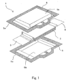
- film-covered battery 1 includes flat and substantially rectangular parallelepiped battery element 2 having a structure with a plurality of positive electrodes and negative electrodes alternately stacked, positive electrode lead 3 and negative electrode lead 4 connected with the positive electrodes and negative electrodes of battery element 2, respectively, and casing films 5 for sealing battery element 2 with positive electrode lead 3 and negative electrode lead 4 partially extending out, thus constructing film-covered battery 1 according to one embodiment of the present invention.
- Battery element 2 has a stacked body wherein the plurality of positive electrodes and negative electrodes alternately stacked with separators intervened, the electrodes being composed of metallic foils both sides of which respective electrode materials are applied onto.
- the stacked body including the positive electrodes, negative electrodes and the separators, is impregnated with electrolyte to construct the battery element.
- Each of the positive electrodes and negative electrodes has an unapplied portion, where no electrode material is applied, protruding from one side. All unapplied portions of the positive electrodes and the negative electrodes are respectively united together, welded by ultrasonic technology, and then connected to positive electrode lead 3 and negative electrode lead 4, respectively.
- the positive electrodes and the negative electrodes are overlaid on one another with their unapplied portions opposing each other. Accordingly, positive lead 3 and negative lead 4 extend out from opposing sides of film-covered battery 1.
- a non-aqueous electrolyte battery such as a lithium-ion battery
- aluminum foil is employed as a positive electrode metal
- copper foil as a negative electrode metal
- An aluminum plate is used for positive electrode lead 3, and a nickel plate or copper plate for negative electrode lead 4. If the copper plate is used for negative electrode lead 4, nickel plating may be applied to its surface.
- a separator there can be employed for a separator a sheet type member, such as micro-porous film, non-woven fabric or fabric made of thermoplastic resin such as polyolefin, capable of impregnating electrolyte.
- a sheet type member such as micro-porous film, non-woven fabric or fabric made of thermoplastic resin such as polyolefin, capable of impregnating electrolyte.
- Casing film 5 is a laminated film, and a pair of casing films 5 is arranged so as to enclose battery element 2 by sandwiching it from both sides in its thickness direction.
- the opposing surfaces of the laminated films overlaid on each other around the periphery of battery element 2 are thermally fused together throughout the periphery of casing films 5 to seal battery element 2.
- This thermal fusing throughout the periphery of casing films 5 allows casing films 5 to have sealing area 5a formed thereon so as to enclose battery element 2 around the periphery, and also to have a battery element receiving part formed inside sealing area 5a as a space for encapsulating battery element 2.
- Sealing area 5a is hatched in Fig. 1.
- Each casing film 5 has cup 5b at its center area to form the battery element receiving part.
- This cup 5b can be formed by a deep drawing mold process.
- Fig. 1 shows an example in which cups 5b are formed on both casing films 5, cup 5b may be formed on either side of the films, or casing film 5 may encapsulate battery element 2 utilizing its flexibility without forming cup 5b.
- the laminated film used in casing film 5 might be made of known films generally used in this type of film-covered battery, as long as they have flexibility and capability to seal battery element 2 without leakage of electrolyte.
- Typical layer structure of the laminated film used in casing film 5 may include a metallic thin film layer and a thermo-fusing resin layer stacked on each other, or a metallic film layer having a protective layer comprising a film made of polyester like polyethylene-telephthalate, nylon, or the like, laminated to the side opposite to where a thermo-fusing resin layer is stacked.
- the thermo-fusing resin layers face each other to enclose battery element 2.
- the metallic thin film layer may be a foil having a thickness of 10-100 ⁇ m made of Al, Ti, Ti alloy, Fe, stainless steel, Mg alloy, or the like.
- resin used for the thermo-fusing resin layer there are no particular limitations regarding the resin used for the thermo-fusing resin layer, as long as it is thermally fusible. There may be employed, for example, polyester such as polypropylene, polyethylene, modifications of these resins, polyphenylene-sulfide and polyethylene-terephthalate, polyamide, ethylene-vinylacetate-copolymer, or the like.
- the thickness of the thermo-fusing resin layer is preferably 10-200 ⁇ m, and more preferably 30-100 ⁇ m.
- sealing area 5a has at one side two unfused portions 7a and 7b where casing films 5 are not thermally fused together, each portion having a shape of cove opening toward cup 5b (battery element receiving part) so as to communicate with cup 5b.
- casing film 5 has a fused prominence 5c protruding outward at the position of unfused portions 7a and 7b so as to keep constant width of sealing area 5a throughout the periphery of the films.
- Two unfused portions 7a and 7b are arranged in a spaced relationship with each other along one side of sealing area 5a, and there is provided at the area between unfused portions 7a and 7b a fused protrusion 5d protruding toward cup 5b from sealing area 5a positioned outside unfused portions 7a and 7b.
- This fused protrusion 5d has through-hole 8 formed therein passing through casing films 5.
- battery element 2 In film-covered battery 1 constructed as described above, if a voltage beyond a rated range is applied to the battery, or temperature rises temporarily during its use, battery element 2 generates gas, which causes the inside pressure of battery 1 to rise. The rise of inside pressure causes casing films 5 to expand in a dome shape, which acts on the thermally fused portions of casing films 5 to produce peeling stress. At this time, the peeling stress is concentrated on fused protrusion 5d between two unfused portions 7a and 7b, so that peeling at fused protrusion 5d proceeds in advance of other thermally fused portions of casing films 5.
- the battery element receiving part communicates with the outside of film-covered battery 1, allowing the risen pressure to be released through through-hole 8.
- the generated gas can be ejected from a predetermined position prior to explosion of battery 1, thereby preventing the breakage of battery 1 and the ejection of gas toward unexpected directions.
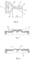
- peeling stress F1 acts in one direction only as shown in Fig. 3, to thereby advancing the peeling of casing films 5 toward the rim thereof.
- fused protrusion 5d receives peeling stress F1 at the top end, and additionally peeling stress F2 at both sides ends.
- fused protrusion 5d receives larger peeling stress at the corners due to resultant forces, which causes the peeling of film 5 at the corners to proceed in advance of the other portions thereof.
- the peeling of film 5 proceeds at the corners, the corners gradually become round, but fused protrusion 5d receives peeling stress from various directions, so far as protrusion 5d maintains convex shapes . Accordingly, the peeling of fused protrusion 5d proceeds in advance of the other portions of films 5, until protrusion 5d finally disappeared with the convex sharpness reduced.
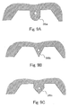
- Fig. 5 shows the progress of peeling of casing films 5 at fused protrusion 5d.
- the peeling at protrusion 5d proceeds from both sides thereof to indicated positions a, b, and c in this order, as the inside pressure rises.
- the peeled position of casing films 5 depends on its material, width W of protrusion 5d, length L of protrusion 5d, and inside pressure. Therefore, if the material of film 5, width W and length L are decided in advance, release pressure can be arbitrarily set by adjusting the position of through-hole 8, the release pressure being an inside pressure of the battery element receiving part at the time of communication between the inside and outside thereof. If through-hole 8 is positioned nearer to the top end of protrusion 5d, the release pressure becomes lower, and if the through-hole 8 is positioned near the root of protrusion 5d, the release pressure becomes high.
- the preferable release pressure in design is a pressure increment of 0.05-1 Mpa over the atmospheric pressure, and more preferably 0.1-0.2 MPa. If the release pressure is very low, even a miner trouble due to, for example, transient large current flow or temporary high temperature causes the inside pressure to be released, leading to malfunction of battery 1. To the contrary, if the release pressure is excessively high, a part of fused portion of film 5 other than through-hole 8 or the sealed areas of the electrode leads might open before the peeled position of films 5 proceeds to through-hole 8, which leads to increased risk such as gas ejection toward unexpected directions.
- casing film 5 was constructed by laminating films, that is, nylon (25 ⁇ m in thickness)/ aluminum (40 ⁇ m in thickness)/ modified polypropylene (15 ⁇ m in thickness)/ polypropylene (30 ⁇ m in thickness). Setting width W of protrusion 5d to 6 mm, and length L to 7 mm, casing film 5 was thermally fused (heating temperature: 190 degrees C, heating time: 2 sec, applied pressure: 1 MPa), and the resultant film was provided for experiment to confirm the progress of peeled position in fused protrusion 5d with the rise of inside pressure. As a result, the peeled edge reached position a in Fig.
- the peeling of films advances ahead from the portion with the inside pressure risen, and releases the pressure, and thus this structure does not need to partially weaken the thermo-fusing strength of casing films 5 as in a conventional structure, and therefore does not reduce sealing reliability.
- the conventional pressure release structure needs to partially weaken the thermo-fusing strength, and therefore it has been difficult to adjust the thermo-fusing strength, but the structure in the embodiment can easily and securely set the release pressure by simply adjusting the position of through-hole 8.
- the stress concentrating portion functioning as a safety valve allows the peeling of films to greatly advance, which makes it possible to release the inside pressure at a lower value, and also to reduce influence of the positional error of a pressure release part, thereby improving setting precision of release pressure.
- fused protrusion 5d in the embodiment is so formed that sealing area 5a is protruded toward the battery element receiving part.
- Fused protrusion 5d does not simply protrude toward the battery element receiving part, but fused protrusion 5d is formed utilizing unfused portions 7a and 7b, each having a shape of cove so as to communicate with the battery element receiving part, so that increase in the outer size of film-covered battery 1 due to this formation of protrusion 5d can be limited to a minimum.
- protruding length L of protrusion 5d is set so that protrusion 5d does not enter the battery element receiving part as shown in Fig. 2, so as not to reduce volume efficiency of the battery element receiving part relative to the outer size of film-covered battery 1.
- this limitation is not particularly critical, in case that the entering of protrusion 5d into the battery element receiving part is not a problem, or that the fused portions is formed with a space apart from the battery element receiving part, although they are usually formed so as to substantially contact the battery element receiving part, and therefore length L may be set to a slightly larger one.
- Casing films 5 in the embodiment have fused prominence 5c as shown in Fig. 2. Resultantly, casing films 5 are securely provided with enough sealing area 5a to seal battery element 2 at the position where unfused portions 7a and 7b are formed, thereby improving the sealing reliability. Additionally, fused prominence 5c has some effects as in the following.
- the outer size of film-covered battery 1 becomes larger due to fused prominence 5c, but the outer size does not substantially increase by folding prominence 5c for practical use.
- rectangular casing films 15 could be used, as shown in Fig. 7, to form sealing area 15a similar to the shape shown in Fig. 1.
- the size of film 15 becomes larger, but process for forming the fused prominence portion would be eliminated.
- casing films 25 as shown in Fig. 8, which has a shape with a portion corresponding to the fused prominence removed. In this case, thermally fused width becomes narrower, but the amount of films 25 used could be reduced.
- the present invention has an effect that the peeling of films at the stress concentrating portion greatly advances according to the rise of inside pressure, whereby the fused width of an expected gas release portion could be larger than a conventional one.
- This larger fused width could regulate the ingress of water at the fused area of the expected gas release portion, resultantly.
- the fused width of the expected gas release portion is distance d from the edge of fused protrusion 5d to the outer edge of through-hole 8 as in Fig. 5 in the invention, and in Japanese Laid-Open Patent Publication No. 2002-5683, for example, it is a residual width of thermally-fused portion when an outer part thereof is cut from the outside.
- the fused width of the expected gas release portion is a length of peeling advancing path in a direction from the space on the side of the battery element receiving part to the rim of casing film 5 within a portion functioning as a safety valve, the path lying up to the position where the space on the side of the battery element receiving part is connected to the open air according to the rise of inside pressure.
- fused protrusion 5d has a rectangular shape in Fig.2, but any shape may be formed, as long as it protrudes toward the battery element receiving part.
- Fused protrusion 36a shown in Fig. 9A has an arc-shaped top end.
- An example shown in Fig. 9B has triangular-shaped fused protrusion 36b.
- Another example shown in Fig. 9C has home-base shaped fused protrusion 36c.
- protrusion 36a, 36b and 36c not only its top end but also its both sides expand, and resultantly peeling stress acts on the top end and both sides, whereby the peeling stress concentrates on the top potion, and the peeling at the top proceeds in advance of the other fused portions.
- protrusion 36b of Fig. 9B and protrusion 36c of Fig. 9C each having a tapering shape with a point end toward the battery element receiving part, are easier for the peeling to proceed from the point end.
- the pressure release part in the invention has been a through-hole in the embodiment described above, but the pressure release part is not limited to a through-hole.
- slit 48 formed on fused protrusion 46 as shown in Fig. 10, achieves the same effect as that in the above embodiment.
- the release pressure can be set arbitrarily by adjusting the top end position of slit 48.
- the pressure release part is not limited to the structure in which an opening passes through two overlaid casing films, as long as the battery element receiving part can communicate with the outside by the peeling of thermally-fused portion.
- a through-hole, a slit or the like could be formed only on one side of two overlaid casing films, which also achieves the same effect.
- the stress concentrating portion it is also not necessary to be provided as a fused protrusion as in above-described examples, as long as the peeling stress is concentrated on a part of a fused portion, and the peeling resultantly progresses in advance of the other portions.
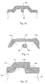
- Fig. 11 shows another example of the stress concentrating portion according to the invention.
- island-shaped fused portion 56 is formed as a stress concentrating portion independent of the other fused portions within an unfused portion having a cove-like shape and opening to the battery element receiving part.
- This island-shaped fused portion 56 has through-hole 58 as a pressure release part formed inside. This structure may be understood such that island-shaped fused portion 56 is provided inside a unfused portion as described above.
- this structure could be construed from a different point of view such that: two cove-like unfused portions 57a and 57b are provided opening to the battery element receiving part, the unfused portions 57a and 57b are communicated through connection 57c as an unfused portion in the casing film, and resultantly island-shaped fused portion 56 is provided as a stress concentrating portion between two unfused portions 57a and 57b.
- the generated gas when gas is generated in the battery element receiving part, the generated gas enters two unfused portions 57a and 57b, and connection 57c, which causes the casing films to expand at the entire circumference of the island-shaped fused portion 56. Resultantly, the peeling stress concentrates on island portion 56, whereby the peeling of films progresses in advance of the other portions.
- the inside pressure is released when the peeled border of the casing films in island portion 56 reaches through-hole 58.
- the release pressure can be arbitrarily set by adjusting the distance from the rim of island portion 56 to through-hole 58.
- Fig. 12 shows still another example of the stress concentrating portion according to the invention.
- unfused portion 67 has a shape of cove relative to the battery element receiving part, and each of both sides 67a and 67b has an angle with side 69a along which unfused portion 67 is provided, and therefore each fused area border around its intersection has a convex shape protruding toward the side of the battery element receiving part from the fused area.
- through-hole 68 is formed in the fused area at the side of receiving part 69 within the area indicated by the broken line.
- the release pressure can be arbitrarily set by properly adjusting the position of through-hole 68.
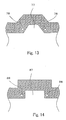
- Fig. 12 has through-hole 68 only at one side of unfused portion 67, but through-holes 78 may be formed in both sides of unfused portion 77, respectively, as shown in Fig. 13.
- This structure would allow securer pressure release.
- though-holes 78 can be provided also within a stress concentrating area.
- Fig. 14 shows another example in which through-holes 88 may be provided in both sides of unfused portion 87, but differs from the example of Fig. 13 in that the shape of unfused portion 87 is rectangular.
- unfused portion 87 could have any shape, as long as it is formed in the shape of cove relative to the battery element receiving part.
- FIG. 11 to 14 shows a structure having a through-hole as a pressure release part, but, as described referring to Fig. 10, the through-hole could be replaced with a slit. Further, the through-hole or the slit may be formed only in one side of overlaid casing films.
- the unfused portion is preferably so constructed that the gas generated by the battery element receiving part can easily enter.
- at least one side of unfused portion may have a taper shape. This shape has a wide frontage in the unfused portion, which allows the gas generated at the battery element receiving part to easily enter the unfused portion.
- the unfused portion may be provided at the center of a longer side of the battery element receiving part. This position is most appropriate for the casing films to expand with in the areas where the unfused portion can be formed. By providing the unfused portion at this position, the gas generated at the battery element receiving part can easily enter the unfused portion.
- a battery element is sandwiched with two casing films from both sides in a thickness direction, and then four sides of peripheries are thermally fused, but as another example, a battery element may be sandwiched by folding a single casing film, and three opening sides are thermally fused to thereby seal the battery element.
- a battery element there has been shown a stacked type one in the above example in which a plurality of positive electrode plates and negative electrode plates are alternately stacked, but there may be employed a wound type battery element having alternately arranged positive electrode and negative electrode, which is made by including the steps of forming a stripe of positive electrode plate, negative electrode plate and separator, overlaying the positive electrode plate and the negative electrode plate with the separator sandwiched between them, winding this, and compressing this wound one into flat shape.
- any battery element used in a usual battery may be also applicable to the battery element of the invention, as long as it includes a positive electrode, a negative electrode and an electrolyte.
- a positive electrode plate is opposed to a negative electrode plate via a separator, and then an electrolyte containing lithium salt is impregnated to form the battery element, the positive electrode plate being made by applying positive active material, such as lithium manganese combined oxide or cobalt acid lithium, onto both surfaces of an aluminum foil, and the negative electrode plate being made by applying carbon material, capable of doping/dedoping lithium, onto both surfaces of a copper foil.
- positive active material such as lithium manganese combined oxide or cobalt acid lithium
- the present invention is also applicable to an electric device in which casing films seal the electric device element that is possible to generate gas by chemical reaction or physical reaction on the electric energy stored inside a capacitor element as represented in an electric double layer capacitor, electrolytic capacitor, or the like.
- Fig. 1 shows an example of film-covered battery 1 having positive electrode lead 3 and negative electrode lead 4 extending from opposing sides of the battery, but these leads may be extended from the same side.
Landscapes
- Chemical & Material Sciences (AREA)
- Chemical Kinetics & Catalysis (AREA)
- Electrochemistry (AREA)
- General Chemical & Material Sciences (AREA)
- Engineering & Computer Science (AREA)
- Power Engineering (AREA)
- Microelectronics & Electronic Packaging (AREA)
- Inorganic Chemistry (AREA)
- Gas Exhaust Devices For Batteries (AREA)
- Sealing Battery Cases Or Jackets (AREA)
- Measuring Fluid Pressure (AREA)
Abstract
Description
Claims (11)
- A film-covered electric device having an electric device element, and a casing film arranged for enclosing said electric device element to seal said electric device element, said casing film comprising:a sealing area formed by thermally fusing the facing surfaces of said casing film together throughout the perimeter of said casing film around the periphery of said electric device element;an electric device element receiving part formed inside said sealing area as a space for encapsulating said electric device element;at least one unfused portion communicating with said electric device element receiving part, and having a shape of cove opening to said electric device element receiving part;a stress concentrating portion touching said unfused portion for concentrating thereon peeling stress of said casing film, the peeling stress being generated by the expansion of said electric device element receiving part according to the rise of inside pressure of said electric device element receiving part; anda pressure release part formed within said stress concentrating portion for opening the inside of said electric device element receiving part to the outside thereof by peeling said casing film.
- The film-covered electric device according to claim 1, wherein said sealing area is formed protruding into the area where said unfused portion is provided.
- The film-covered electric device according to claim 1, wherein said pressure release part is a hole or a slit formed at least in one side of said casing film overlaid at said stress concentrating portion.
- The film-covered electric device according to claim 1, wherein two unfused portions are provided in spaced relationship with each other along the periphery of said sealing area, and said stress concentrating portion is located between said two unfused portions.
- The film-covered electric device according to claim 4, wherein said stress concentrating portion is formed as a fused protrusion protruding toward said electric device element receiving part from said sealing area positioned outside said two unfused portions.
- The film-covered electric device according to claim 5, wherein said fused protrusion has a shape tapering toward said electric device element receiving part.
- The film-covered electric device according to claim 4, wherein said stress concentrating portion is formed as an island-shaped fused portion located between said two unfused portions.
- The film-covered electric device according to claim 1, wherein one unfused portion is provided in said casing film, and both sides of said unfused portion are said stress concentrating portions.
- The film-covered electric device according to claim 8, wherein said pressure release part is formed on each of said stress concentrating portions provided on both sides of said unfused portion.
- The film-covered electric device according to claim 1, wherein said pressure release part is so positioned that, when the inside of said electric device element receiving part opens to the outside, the inside pressure of said electric device element receiving part increases over the atmospheric pressure by 0.1 to 0.2 MPa.
- The film-covered electric device according to claim 1, wherein said electric device element is a chemical battery element or a capacitor element.
Applications Claiming Priority (2)
| Application Number | Priority Date | Filing Date | Title |
|---|---|---|---|
| JP2004009230A JP3859645B2 (en) | 2004-01-16 | 2004-01-16 | Film exterior electrical device |
| JP2004009230 | 2004-01-16 |
Publications (3)
| Publication Number | Publication Date |
|---|---|
| EP1555702A2 true EP1555702A2 (en) | 2005-07-20 |
| EP1555702A3 EP1555702A3 (en) | 2005-08-03 |
| EP1555702B1 EP1555702B1 (en) | 2010-12-01 |
Family
ID=34616909
Family Applications (1)
| Application Number | Title | Priority Date | Filing Date |
|---|---|---|---|
| EP05090003A Expired - Lifetime EP1555702B1 (en) | 2004-01-16 | 2005-01-08 | Film-covered electric device having pressure release opening |
Country Status (6)
| Country | Link |
|---|---|
| US (2) | US7267906B2 (en) |
| EP (1) | EP1555702B1 (en) |
| JP (1) | JP3859645B2 (en) |
| KR (1) | KR100705101B1 (en) |
| CN (1) | CN1300861C (en) |
| DE (1) | DE602005025048D1 (en) |
Cited By (1)
| Publication number | Priority date | Publication date | Assignee | Title |
|---|---|---|---|---|
| EP1739766A4 (en) * | 2004-03-23 | 2010-07-28 | Nec Corp | ELECTRIC FILM DEVICE AND METHOD OF MANUFACTURING THE SAME |
Families Citing this family (63)
| Publication number | Priority date | Publication date | Assignee | Title |
|---|---|---|---|---|
| US8445130B2 (en) | 2002-08-09 | 2013-05-21 | Infinite Power Solutions, Inc. | Hybrid thin-film battery |
| US8021778B2 (en) | 2002-08-09 | 2011-09-20 | Infinite Power Solutions, Inc. | Electrochemical apparatus with barrier layer protected substrate |
| US8394522B2 (en) | 2002-08-09 | 2013-03-12 | Infinite Power Solutions, Inc. | Robust metal film encapsulation |
| US7993773B2 (en) | 2002-08-09 | 2011-08-09 | Infinite Power Solutions, Inc. | Electrochemical apparatus with barrier layer protected substrate |
| US8431264B2 (en) | 2002-08-09 | 2013-04-30 | Infinite Power Solutions, Inc. | Hybrid thin-film battery |
| US8404376B2 (en) | 2002-08-09 | 2013-03-26 | Infinite Power Solutions, Inc. | Metal film encapsulation |
| US8236443B2 (en) | 2002-08-09 | 2012-08-07 | Infinite Power Solutions, Inc. | Metal film encapsulation |
| US20070264564A1 (en) | 2006-03-16 | 2007-11-15 | Infinite Power Solutions, Inc. | Thin film battery on an integrated circuit or circuit board and method thereof |
| US8728285B2 (en) | 2003-05-23 | 2014-05-20 | Demaray, Llc | Transparent conductive oxides |
| JP4830267B2 (en) * | 2004-05-21 | 2011-12-07 | トヨタ自動車株式会社 | Laminated battery |
| JP4232038B2 (en) | 2004-08-11 | 2009-03-04 | 日本電気株式会社 | Film-clad electrical device and method for manufacturing the same |
| US7959769B2 (en) | 2004-12-08 | 2011-06-14 | Infinite Power Solutions, Inc. | Deposition of LiCoO2 |
| KR101127370B1 (en) | 2004-12-08 | 2012-03-29 | 인피니트 파워 솔루션스, 인크. | Deposition of licoo2 |
| US8062780B2 (en) | 2005-03-17 | 2011-11-22 | Nec Corporation | Film-covered electric device and method of manufacturing same |
| JP4911909B2 (en) * | 2005-03-29 | 2012-04-04 | 三洋電機株式会社 | Method for producing electrode for lithium secondary battery |
| JP2007157678A (en) * | 2005-05-23 | 2007-06-21 | Matsushita Electric Ind Co Ltd | Laminated battery safety mechanism |
| JP4876481B2 (en) * | 2005-08-18 | 2012-02-15 | トヨタ自動車株式会社 | Laminated battery and laminated battery module |
| JP4956968B2 (en) * | 2005-11-18 | 2012-06-20 | トヨタ自動車株式会社 | Battery module |
| JP5114018B2 (en) * | 2006-05-18 | 2013-01-09 | Necエナジーデバイス株式会社 | Film-clad electrical device and manufacturing method thereof |
| KR20090069323A (en) | 2006-09-29 | 2009-06-30 | 인피니트 파워 솔루션스, 인크. | Masking of the flexible substrate and restraint of the material for depositing a battery layer on the flexible substrate |
| US8197781B2 (en) | 2006-11-07 | 2012-06-12 | Infinite Power Solutions, Inc. | Sputtering target of Li3PO4 and method for producing same |
| US8722241B2 (en) | 2007-02-21 | 2014-05-13 | Nec Corporation | Packaged battery, stacked battery assembly, and film-covered battery |
| JP5329527B2 (en) * | 2007-04-20 | 2013-10-30 | エルジー・ケム・リミテッド | Battery cell with improved safety |
| KR100944987B1 (en) * | 2007-12-14 | 2010-03-02 | 주식회사 엘지화학 | Secondary battery including novel sealing part structure |
| WO2009086038A1 (en) | 2007-12-21 | 2009-07-09 | Infinite Power Solutions, Inc. | Method for sputter targets for electrolyte films |
| US8268488B2 (en) | 2007-12-21 | 2012-09-18 | Infinite Power Solutions, Inc. | Thin film electrolyte for thin film batteries |
| CN101911367B (en) | 2008-01-11 | 2015-02-25 | 无穷动力解决方案股份有限公司 | Thin film encapsulation for thin film batteries and other devices |
| KR101672254B1 (en) | 2008-04-02 | 2016-11-08 | 사푸라스트 리써치 엘엘씨 | Passive over/under voltage control and protection for energy storage devices associated with energy harvesting |
| US8906523B2 (en) | 2008-08-11 | 2014-12-09 | Infinite Power Solutions, Inc. | Energy device with integral collector surface for electromagnetic energy harvesting and method thereof |
| WO2010030743A1 (en) | 2008-09-12 | 2010-03-18 | Infinite Power Solutions, Inc. | Energy device with integral conductive surface for data communication via electromagnetic energy and method thereof |
| US8508193B2 (en) | 2008-10-08 | 2013-08-13 | Infinite Power Solutions, Inc. | Environmentally-powered wireless sensor module |
| US20100248010A1 (en) | 2009-01-12 | 2010-09-30 | A123 Systems, Inc. | Bi-metallic busbar jumpers for battery systems |
| JP5178606B2 (en) * | 2009-03-31 | 2013-04-10 | Jmエナジー株式会社 | Laminate exterior power storage device |
| JP5059890B2 (en) * | 2009-03-31 | 2012-10-31 | Jmエナジー株式会社 | Laminate exterior power storage device |
| KR20120025521A (en) * | 2009-05-20 | 2012-03-15 | 인피니트 파워 솔루션스, 인크. | Method of integrating electrochemical devices into and onto fixtures |
| US8599572B2 (en) | 2009-09-01 | 2013-12-03 | Infinite Power Solutions, Inc. | Printed circuit board with integrated thin film battery |
| JP5364548B2 (en) * | 2009-12-03 | 2013-12-11 | Udトラックス株式会社 | Module power storage unit and manufacturing method thereof |
| JP2011129446A (en) * | 2009-12-21 | 2011-06-30 | Hitachi Maxell Ltd | Laminated type battery |
| JP2011198742A (en) * | 2010-02-26 | 2011-10-06 | Hitachi Maxell Energy Ltd | Laminated type battery |
| KR101155917B1 (en) * | 2010-03-11 | 2012-06-20 | 삼성에스디아이 주식회사 | Rechargeable battery |
| KR101424003B1 (en) * | 2010-03-25 | 2014-08-01 | 주식회사 엘지화학 | Pouch-type Secondary Battery for preventing swelling phenomena |
| EP2577777B1 (en) | 2010-06-07 | 2016-12-28 | Sapurast Research LLC | Rechargeable, high-density electrochemical device |
| KR101182275B1 (en) | 2010-11-02 | 2012-09-12 | 삼성에스디아이 주식회사 | Rechargeable battery |
| JP5987336B2 (en) | 2011-03-25 | 2016-09-07 | 日本電気株式会社 | Secondary battery |
| JP5800599B2 (en) * | 2011-06-24 | 2015-10-28 | 株式会社Kri | Power storage device |
| KR20140013132A (en) * | 2012-07-09 | 2014-02-05 | 에스케이이노베이션 주식회사 | Secondary battery |
| WO2014147808A1 (en) * | 2013-03-22 | 2014-09-25 | オートモーティブエナジーサプライ株式会社 | Inspection method for film covered battery |
| JP6365191B2 (en) * | 2014-10-01 | 2018-08-01 | 株式会社Gsユアサ | Power storage device and gas exhaust method thereof |
| JP6634671B2 (en) * | 2014-12-10 | 2020-01-22 | 日本電気株式会社 | Secondary battery, electric vehicle, power storage system, and manufacturing method |
| US10381171B2 (en) | 2015-03-04 | 2019-08-13 | Taiyo Yuden Co., Ltd. | Electric storage cell, covering film and electric storage module |
| JPWO2017047473A1 (en) * | 2015-09-15 | 2018-08-02 | Necエナジーデバイス株式会社 | battery |
| JP6752628B2 (en) | 2016-06-03 | 2020-09-09 | 太陽誘電株式会社 | Power storage cell and power storage module |
| JP6644650B2 (en) * | 2016-06-29 | 2020-02-12 | 太陽誘電株式会社 | Power storage cell, exterior film and power storage module |
| JP6851058B2 (en) * | 2016-07-04 | 2021-03-31 | 株式会社エンビジョンAescジャパン | Film exterior battery |
| JP6960016B2 (en) * | 2016-07-04 | 2021-11-05 | 株式会社エンビジョンAescジャパン | Film exterior battery |
| JP6783583B2 (en) * | 2016-08-15 | 2020-11-11 | 太陽誘電株式会社 | Power storage cell, exterior film and power storage module |
| JP6835505B2 (en) * | 2016-08-30 | 2021-02-24 | 太陽誘電株式会社 | Power storage cell, exterior film and power storage module |
| JP6974092B2 (en) | 2017-09-27 | 2021-12-01 | 太陽誘電株式会社 | Power storage module |
| JP6974104B2 (en) | 2017-10-11 | 2021-12-01 | 太陽誘電株式会社 | Power storage module |
| KR102076935B1 (en) * | 2019-06-21 | 2020-02-13 | 주식회사 에스피씨지에프에스 | Packaging bag |
| JP7638690B2 (en) * | 2020-12-11 | 2025-03-04 | 日本航空電子工業株式会社 | DEVICE AND METHOD FOR MANUFACTURING DEVICE - Patent application |
| CN113241466B (en) * | 2021-05-11 | 2022-07-26 | 宜春清陶能源科技有限公司 | Packaging process of battery |
| EP4542762A4 (en) * | 2023-02-28 | 2025-11-26 | Contemporary Amperex Technology Hong Kong Ltd | BATTERY CELL, BATTERY AND ELECTRICAL DEVICE |
Family Cites Families (10)
| Publication number | Priority date | Publication date | Assignee | Title |
|---|---|---|---|---|
| US4678725A (en) * | 1983-05-11 | 1987-07-07 | Matsushita Electric Industrial Co., Inc. | Hermetically sealed storage battery |
| JPS6455792A (en) * | 1987-08-27 | 1989-03-02 | Canon Kk | Recording and reproducing device |
| JPH1055792A (en) * | 1996-08-12 | 1998-02-24 | Yuasa Corp | Thin battery |
| FR2754938A1 (en) * | 1996-10-22 | 1998-04-24 | Philips Electronics Nv | SEALED HOUSING TO CONTAIN AN ELECTRICAL ACCUMULATOR |
| JP3554155B2 (en) * | 1997-07-24 | 2004-08-18 | 東芝電池株式会社 | Lithium secondary battery and method of manufacturing the same |
| JP2000100399A (en) | 1998-09-21 | 2000-04-07 | Toshiba Battery Co Ltd | Manufacture of polymer lithium secondary battery |
| JP4069565B2 (en) | 2000-02-07 | 2008-04-02 | 株式会社ジーエス・ユアサコーポレーション | Sealed battery |
| JP4862211B2 (en) | 2000-08-08 | 2012-01-25 | 株式会社Gsユアサ | Sealed secondary battery |
| JP2003132868A (en) | 2001-10-25 | 2003-05-09 | Mitsubishi Cable Ind Ltd | Sheet battery |
| KR20030066895A (en) * | 2002-02-05 | 2003-08-14 | 삼성에스디아이 주식회사 | Secondary battery |
-
2004
- 2004-01-16 JP JP2004009230A patent/JP3859645B2/en not_active Expired - Lifetime
-
2005
- 2005-01-08 EP EP05090003A patent/EP1555702B1/en not_active Expired - Lifetime
- 2005-01-08 DE DE602005025048T patent/DE602005025048D1/en not_active Expired - Lifetime
- 2005-01-13 KR KR1020050003250A patent/KR100705101B1/en not_active Expired - Lifetime
- 2005-01-14 US US11/034,715 patent/US7267906B2/en not_active Expired - Lifetime
- 2005-01-17 CN CNB2005100057299A patent/CN1300861C/en not_active Expired - Lifetime
-
2007
- 2007-07-31 US US11/831,209 patent/US7579111B2/en not_active Expired - Lifetime
Cited By (2)
| Publication number | Priority date | Publication date | Assignee | Title |
|---|---|---|---|---|
| EP1739766A4 (en) * | 2004-03-23 | 2010-07-28 | Nec Corp | ELECTRIC FILM DEVICE AND METHOD OF MANUFACTURING THE SAME |
| EP3038184A1 (en) * | 2004-03-23 | 2016-06-29 | Nec Corporation | Film-packaged electric device and its manufacturing method |
Also Published As
| Publication number | Publication date |
|---|---|
| KR20050075702A (en) | 2005-07-21 |
| JP3859645B2 (en) | 2006-12-20 |
| US20050158622A1 (en) | 2005-07-21 |
| US20080008936A1 (en) | 2008-01-10 |
| US7579111B2 (en) | 2009-08-25 |
| CN1300861C (en) | 2007-02-14 |
| EP1555702A3 (en) | 2005-08-03 |
| US7267906B2 (en) | 2007-09-11 |
| KR100705101B1 (en) | 2007-04-06 |
| CN1641903A (en) | 2005-07-20 |
| JP2005203262A (en) | 2005-07-28 |
| EP1555702B1 (en) | 2010-12-01 |
| DE602005025048D1 (en) | 2011-01-13 |
Similar Documents
| Publication | Publication Date | Title |
|---|---|---|
| EP1555702B1 (en) | Film-covered electric device having pressure release opening | |
| US8283061B2 (en) | Film-encased electric device and production method therefor | |
| JP4249698B2 (en) | Film-clad electrical device and film-clad electrical device assembly | |
| US7901806B2 (en) | Film-armored battery and method of manufacturing the battery | |
| CN101617419B (en) | Encapsulated batteries, laminated laminated battery packs, and film-covered batteries | |
| JP3730981B2 (en) | Film outer battery and battery pack | |
| JP4336764B2 (en) | Film-clad electrical device and method for manufacturing the same | |
| JP2013105742A (en) | Battery cell, and battery module including the same | |
| JP7067300B2 (en) | Battery module and battery module manufacturing method | |
| WO2007043510A1 (en) | System for receiving film-coated electric device | |
| JP2019036514A (en) | Power storage module and manufacturing method of the same | |
| JP4397175B2 (en) | Electricity storage element | |
| WO2017047473A1 (en) | Battery | |
| JP2001222986A (en) | Sealed battery | |
| JPWO2017047473A6 (en) | battery | |
| CN107785605B (en) | Single storage battery, packaging film and storage battery assembly | |
| WO2019073791A1 (en) | Power storage module | |
| JP5114018B2 (en) | Film-clad electrical device and manufacturing method thereof | |
| JP2020035665A (en) | Supply device | |
| KR20220007519A (en) | Rechargeable battery | |
| CN115832543A (en) | Secondary battery | |
| JP2018206679A (en) | Power storage module | |
| JP7067301B2 (en) | Battery module and battery module manufacturing method | |
| JP2015185371A (en) | Power storage device | |
| JP2020087590A (en) | Power-storage module |
Legal Events
| Date | Code | Title | Description |
|---|---|---|---|
| PUAI | Public reference made under article 153(3) epc to a published international application that has entered the european phase |
Free format text: ORIGINAL CODE: 0009012 |
|
| PUAL | Search report despatched |
Free format text: ORIGINAL CODE: 0009013 |
|
| AK | Designated contracting states |
Kind code of ref document: A2 Designated state(s): AT BE BG CH CY CZ DE DK EE ES FI FR GB GR HU IE IS IT LI LT LU MC NL PL PT RO SE SI SK TR |
|
| AX | Request for extension of the european patent |
Extension state: AL BA HR LV MK YU |
|
| AK | Designated contracting states |
Kind code of ref document: A3 Designated state(s): AT BE BG CH CY CZ DE DK EE ES FI FR GB GR HU IE IS IT LI LT LU MC NL PL PT RO SE SI SK TR |
|
| AX | Request for extension of the european patent |
Extension state: AL BA HR LV MK YU |
|
| 17P | Request for examination filed |
Effective date: 20050804 |
|
| RIN1 | Information on inventor provided before grant (corrected) |
Inventor name: OTOHATA, MAKIHIRO C/O NEC LAMILION ENERGY LTD Inventor name: MIZUTA, MASATOMO C/O NEC LAMILION ENERGY LTD Inventor name: OIKAWA, KIYOKAZU C/O NEC LAMILION ENERGY LTD Inventor name: YAGETA, HIROSHI C/O NEC LAMILION ENERGY LTD Inventor name: MANKYU, TOSHIHIKO C/O NEC LAMILION ENERGY LTD |
|
| RAP1 | Party data changed (applicant data changed or rights of an application transferred) |
Owner name: NEC LAMILION ENERGY, LTD. |
|
| AKX | Designation fees paid |
Designated state(s): DE FR IT |
|
| RAP1 | Party data changed (applicant data changed or rights of an application transferred) |
Owner name: NEC CORPORATION |
|
| GRAP | Despatch of communication of intention to grant a patent |
Free format text: ORIGINAL CODE: EPIDOSNIGR1 |
|
| GRAS | Grant fee paid |
Free format text: ORIGINAL CODE: EPIDOSNIGR3 |
|
| GRAA | (expected) grant |
Free format text: ORIGINAL CODE: 0009210 |
|
| AK | Designated contracting states |
Kind code of ref document: B1 Designated state(s): DE FR IT |
|
| REF | Corresponds to: |
Ref document number: 602005025048 Country of ref document: DE Date of ref document: 20110113 Kind code of ref document: P |
|
| PLBE | No opposition filed within time limit |
Free format text: ORIGINAL CODE: 0009261 |
|
| STAA | Information on the status of an ep patent application or granted ep patent |
Free format text: STATUS: NO OPPOSITION FILED WITHIN TIME LIMIT |
|
| 26N | No opposition filed |
Effective date: 20110902 |
|
| REG | Reference to a national code |
Ref country code: DE Ref legal event code: R097 Ref document number: 602005025048 Country of ref document: DE Effective date: 20110902 |
|
| REG | Reference to a national code |
Ref country code: FR Ref legal event code: PLFP Year of fee payment: 12 |
|
| REG | Reference to a national code |
Ref country code: FR Ref legal event code: PLFP Year of fee payment: 13 |
|
| REG | Reference to a national code |
Ref country code: FR Ref legal event code: PLFP Year of fee payment: 14 |
|
| REG | Reference to a national code |
Ref country code: DE Ref legal event code: R079 Ref document number: 602005025048 Country of ref document: DE Free format text: PREVIOUS MAIN CLASS: H01M0002000000 Ipc: H01M0050000000 |
|
| PGFP | Annual fee paid to national office [announced via postgrant information from national office to epo] |
Ref country code: DE Payment date: 20240119 Year of fee payment: 20 |
|
| PGFP | Annual fee paid to national office [announced via postgrant information from national office to epo] |
Ref country code: IT Payment date: 20240129 Year of fee payment: 20 Ref country code: FR Payment date: 20240124 Year of fee payment: 20 |
|
| REG | Reference to a national code |
Ref country code: DE Ref legal event code: R071 Ref document number: 602005025048 Country of ref document: DE |