EP1555554A1 - Optisches Modul für ein bidirektionales Kommunikationssystem - Google Patents
Optisches Modul für ein bidirektionales Kommunikationssystem Download PDFInfo
- Publication number
- EP1555554A1 EP1555554A1 EP04255768A EP04255768A EP1555554A1 EP 1555554 A1 EP1555554 A1 EP 1555554A1 EP 04255768 A EP04255768 A EP 04255768A EP 04255768 A EP04255768 A EP 04255768A EP 1555554 A1 EP1555554 A1 EP 1555554A1
- Authority
- EP
- European Patent Office
- Prior art keywords
- light
- optical
- attachment section
- optical module
- support member
- Prior art date
- Legal status (The legal status is an assumption and is not a legal conclusion. Google has not performed a legal analysis and makes no representation as to the accuracy of the status listed.)
- Withdrawn
Links
Images


Classifications
-
- G—PHYSICS
- G02—OPTICS
- G02B—OPTICAL ELEMENTS, SYSTEMS OR APPARATUS
- G02B6/00—Light guides; Structural details of arrangements comprising light guides and other optical elements, e.g. couplings
- G02B6/24—Coupling light guides
- G02B6/42—Coupling light guides with opto-electronic elements
- G02B6/4201—Packages, e.g. shape, construction, internal or external details
- G02B6/4219—Mechanical fixtures for holding or positioning the elements relative to each other in the couplings; Alignment methods for the elements, e.g. measuring or observing methods especially used therefor
-
- G—PHYSICS
- G02—OPTICS
- G02B—OPTICAL ELEMENTS, SYSTEMS OR APPARATUS
- G02B6/00—Light guides; Structural details of arrangements comprising light guides and other optical elements, e.g. couplings
- G02B6/24—Coupling light guides
- G02B6/42—Coupling light guides with opto-electronic elements
- G02B6/4201—Packages, e.g. shape, construction, internal or external details
- G02B6/4246—Bidirectionally operating package structures
-
- G—PHYSICS
- G02—OPTICS
- G02B—OPTICAL ELEMENTS, SYSTEMS OR APPARATUS
- G02B6/00—Light guides; Structural details of arrangements comprising light guides and other optical elements, e.g. couplings
- G02B6/24—Coupling light guides
- G02B6/42—Coupling light guides with opto-electronic elements
- G02B6/4201—Packages, e.g. shape, construction, internal or external details
- G02B6/4204—Packages, e.g. shape, construction, internal or external details the coupling comprising intermediate optical elements, e.g. lenses, holograms
- G02B6/4214—Packages, e.g. shape, construction, internal or external details the coupling comprising intermediate optical elements, e.g. lenses, holograms the intermediate optical element having redirecting reflective means, e.g. mirrors, prisms for deflecting the radiation from horizontal to down- or upward direction toward a device
Definitions
- the present invention relates to an optical module and particularly to an optical module for bi-directional communication system.
- an optical module has to be used between an optical fiber and a terminal in order to connect the optical fiber to the terminal.
- An optical module is a device that converts optical signals received from the optical fiber to electric signals and supplies the electric signals to the terminal, and converts electric signals from the terminal to optical signals that are supplied to the optical fiber.
- various types of optical module have been proposed.
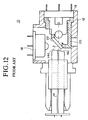
- Figure 12 is a cross-sectional diagram showing the structure of a conventional optical module 10 described in Japanese Utility Model Registration No. 3, 095, 902.
- the optical module 10 includes a main housing 12, an optical fiber 14 supported by the optical module 10, a light-emitting component 16, a light-receiving component 18, a filter support member 20 provided in the main housing 12, and an optical filter 22 supported by the filter support member 20.
- the optical fiber 14 and light-receiving component 16 are disposed in a straight line and the light-receiving component 18 is disposed at an angle of 90 degrees to the straight line.
- the optical filter 22 reflects received light 14a supplied from the optical fiber 14 and transmits transmitted light 16a produced by the light-emitting component 16.
- the filter support member 20 supports the optical filter 22 at an angle of 45 degrees to the straight line.
- This arrangement enables an optical signal received from the optical fiber 14 to be converted to an electric signal and supplied to the terminal, and an electric signal provided from the terminal to be converted to an optical signal and supplied to the optical fiber 14, thereby enabling bi-directional communication between terminals using optical signals.
- the transmitted light 16a produced by the light-emitting component 16 can stray and scatter within the main housing 12, and if this scattered light reaches the light-receiving component 18, it can result in noise, with respect to the received signal.
- One way of resolving this problem is to provide another optical filter at the light-receiving component 18 end to block stray light.
- the provision of another member to support the optical filter further increases the number of parts.
- an increase in the number of parts such as the filter support members, which are small and irregular in shape, makes the manufacturing process more complicated and increases the cost of the products.
- Another object of the present invention is to provide an optical module that reduces noise caused by stray light while keeping down the increase in small, irregularly-shaped parts.
- an optical module comprising:
- two optical filters are supported by a single filter support member, making it possible to keep down the increase in the number of parts.
- the optical filters can be positioned with good precision, with almost no deviation arising in the positional relationship of the filters.
- having the filter support member and light-receiving component supported by the third attachment section is also advantageous in that deviation does not readily arise in the positional relationship of the two filters and the light-receiving component.
- the second angle to be half the first angle.
- the first angle it is preferable for the first angle to be substantially 90 degrees and the second angle substantially 45 degrees.
- having the first optical filter reflecting light supplied by the optical fiber and transmitting light produced by the light-emitting component makes it possible for light from the optical fiber to fall incident on the light-receiving component and light emitted by the light-emitting component to be supplied to the optical fiber.
- the first optical filter can reflect a light supplied from the optical fiber and can transmit a light emitted from the light-emitting component
- the second optical filter can transmit a light supplied from the optical fiber and can reflect a light emitted from the light-emitting component.
- the filter support member has a cap portion, the cap portion of the filter support member being put into the third attachment portion, the light-receiving component being put into the cap portion of the filter support member. According to this aspect of the present invention, the light-receiving component and filter support member can be held securely by the third attachment section.
- the filter support member further has first and second projecting portions each of which has the first surface, the straight line passing between the first and second projecting portions. According to this aspect of the present invention, light from the light-emitting component can be securely supplied to the optical fiber without being blocked by the filter support member.
- the cap portion of the filter support member includes a cylindrical portion intervening between the third attachment section of the main housing and the light-receiving component and a stop portion provided one end of the cylindrical portion that functions as a stop for the light-receiving component.
- the light-receiving component can be accurately positioned relative to the filter support member.
- the cap portion of the filter support member includes a first cylindrical portion intervening between the third attachment section of the main housing and the light-receiving component, a second cylindrical portion having smaller diameter than that of the first cylindrical portion, a stop portion connecting the first and second cylindrical portions, and a filter mounting portion provided one end of the second cylindrical portion having an opening, in which the stop portion functions as a stop for the light-receiving component and the filter mounting portion has the second surface.
- any lenses or other projecting parts included in the light-receiving component do not interfere with the filter support member.
- the optical module further comprises a slider attached to the first attachment section which can adjust a position of the optical fiber in a direction along an optical axis. More preferably, the slider has a cylindrical structure into which a ferrule can be inserted.
- the optical module further comprises another slider attached to the first attachment section which can adjust a position of the optical fiber in a direction perpendicular to the optical axis.
- the second attachment section can adjust a position of the light-emitting component in a direction perpendicular to the optical axis.
- the main housing has a cylindrical structure, the first attachment section being located at one end of the main housing and the second attachment section being located at an opposite end of the main housing.
- the main housing has a cavity at the third attachment section to accommodate at least part of the cap portion of the filter support member. Providing a cavity makes it possible to increase the strength of received signals by bringing the end of the optical fiber closer to the light-receiving component.
- the first attachment section can fix the optical fiber with a tilt for the straight line that preferably is not more than 5 degrees. Even when the optical fiber is cut at a predetermined inclination this arrangement makes it possible to compensate for the effects of the inclination, thereby ensuring that the optical fiber is efficiently connected to the light-emitting component.
- Figure 1 is a cross-sectional view of the configuration of an optical module 100 according to a preferred embodiment of the present invention
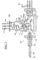
- Figure 2 is an exploded cross-sectional view of the optical module 100.
- the optical module 100 includes a main housing 110, a fiber support component 120 affixed to the main housing 110, a light-emitting component 130, a light-receiving component 140, a filter support member 150 provided so that it covers the light-receiving component 140, and first and second optical filters 161 and 162 that are held by the filter support member 150.
- the optical module 100 is used to carry out bi-directional communication between terminals using optical signals.
- the optical module 100 does this by receiving optical signals from an optical fiber 121 that have a wavelength of, for example, about 1500 nm and converting them to electric signals, and converting electric signals from a terminal to optical signals that have a wavelength of, for example, about 1300 nm, and supplying the optical signals to the optical fiber 121.
- the main housing 110 has a cylindrical structure. As shown in Figure 2, one end of the main housing 110 is provided with a first attachment section 111 for affixing the fiber support component 120, and the other end has a second attachment section 112 for affixing the light-emitting component 130.
- the third attachment section 113 has a cavity shaped to allow accommodation of part of the filter support member 150. While there is no particular limitation on the material of the main housing 110, from the standpoint of mechanical strength and machining precision, it is preferable to use metal.
- the fiber support component 120 is attached in the direction indicated by the arrow 120a in Figure 2, and is thereby held by the first attachment section 111, where it functions by holding the end of the optical fiber 121 as the optical signal transmission medium, and the optical fiber cover 122.
- the fiber support component 120 includes a ring-shaped first slider 123, and a cylindrical second slider 124 into which is inserted a ferrule 125 that holds the end portion of the optical fiber 121.
- the first slider 123 can slidably move in the X direction (vertically with respect to Figure 1) and the Y direction (normal to the page on which Figure 1 is drawn), which allows the position of the optical fiber 121 to be adjusted perpendicularly to the optical axis.
- the second slider 124 can slidably move in the Z direction (from side to side with respect to Figure 1) relative to the first slider 123, which allows the position of the optical fiber 121 to be adjusted along the line of the optical axis. While there is no particular limitation on the material of the first and second sliders 123 and 124, from the standpoint of mechanical strength and machining precision, it is preferable to use metal.
- the light-emitting component 130 is attached in the direction indicated by the arrow 130a in Figure 2, and is thereby held by the second attachment section 112.
- the light-emitting component 130 includes a light-emitting element 131, such as a laser diode or the like, a lens 132 that concentrates the transmitting light 100a emitted by the light-emitting element 131, and signal pins 133 that receive the electric signals from a terminal.
- the function of the light-emitting component 130 is to use the light-emitting element 131 to convert an electric signal received from the terminal via the signal pins 133 into an optical signal, and transmit the optical signal to the optical fiber 121, via the lens 132.
- the lens 132 is not an essential component of the light-emitting component 130, and may therefore be omitted.
- the light-receiving component 140 and filter support member 150 are attached in the directions indicated by the arrows 140a and 150a in Figure 2, whereby they are held by the third attachment section 113.
- the light-receiving component 140 includes a light-receiving element 141, such as a photodiode or the like, a lens 142 that concentrates the receiving light 100b from the optical fiber 121 to the light-receiving element 141, and signal pins 143 that supply electric signals to a terminal.
- the function of the light-receiving component 140 is to use the light-receiving element 141 to convert an optical signal received via the lens 142 into an electric signal, and transmit the electric signal to the terminal, via the signal pins 143.
- the lens 142 is not an essential component of the light-emitting component 140, and may therefore be omitted.
- Figure 3 is a perspective view showing the structure of the filter support member 150 in more detail.
- the filter support member 150 comprises a first cylindrical portion 151, a second cylindrical portion 152 having a smaller diameter than that of the first cylindrical portion 151, a stop portion 153 that connects the first and second cylindrical portions 151 and 152, a filter mounting portion 154 with an opening 154a provided at one end of the second cylindrical portion 152, and first and second projecting portions 155 and 156 provided on the filter mounting portion 154.
- the first cylindrical portion 151, second cylindrical portion 152, stop portion 153 and filter mounting portion 154 comprise a cap portion.
- the cap portion of the filter support member 150 is set into the third attachment section 113, and the light-receiving component 140 is set into the cap portion. Therefore, when the light-receiving component 140 and filter support member 150 are held by the third attachment section 113, the first cylindrical portion 151 is set between the third attachment section 113 and the light-receiving component 140.
- the stop portion 153 acts as a stop to the inserted light-receiving component 140, so that the light-receiving component 140 is accurately positioned with respect to the filter support member 150.
- the first and second projecting portions 155 and 156 are curved parts formed by cutting a section of a cylinder, and are arranged on either side of a straight line connecting the first attachment section 111 and the second attachment section 112, that is, on either side of the path of the transmitting light 100a. This enables the transmitting light 100a from the light-emitting component 130 to be supplied to the optical fiber 121 without being blocked by the filter support member 150.
- the first and second projecting portions 155 and 156 each has a surface (first surface) 157 that is at an angle of 45 degrees to the path of the transmitting light 100a.
- the first optical filter 161 is maintained on this first surface 157.
- the filter mounting portion 154 also has a surface (second surface) 158 that is substantially perpendicular to the light-receiving component 140, and on which the second optical filter 162 is maintained.
- the first optical filter 161 reflects the receiving light 100b from the optical fiber 121 and transmits the transmitting light 100a from the light-emitting component 130.
- the second optical filter 162 transmits the receiving light 100b from the optical fiber 121 and reflects the transmitting light 100a from the light-emitting component 130. Therefore, while the transmitting light 100a produced by the light-emitting component 130 is transmitted by the first optical filter 161 to the optical fiber 121, the receiving light 100b from the optical fiber 121 is reflected by the first optical filter 161, changing the path 90 degrees, after which the light falls substantially perpendicularly incident on the second optical filter 162 and is thereby transmitted to the light-receiving component 140.
- the optical module 100 has the above-described configuration. Since the transmitting light 100a is reflected by the second optical filter 162, even if the transmitting light 100a should stray and scatter in the main housing 110, the stray light is blocked by the second optical filter 162 from reaching the light-receiving component 140. This enables noise caused by stray light to be reduced. Moreover, because in the case of this optical module 100 the two optical filters 161 and 162 are held by just the one filter support member 150, it is possible to keep down the number of parts. Having the two optical filters 161 and 162 held by the one filter support member 150 also provides good positioning accuracy, since there is almost no deviation in the positional relationship of the two filters.
- the filter support member 150 is not limited to the structure shown in Figure 3, but can instead have various other types of structure.
- the first and second projecting portion 155 and 156 can be flat plates, or as shown in Figure 5, the first projecting portion 155 can be divided to form the two projecting portions 155a and 155b and the second projecting portion 156 can be divided to form the two projecting portions 156a and 156b.
- part of the first projecting portion 155 (155b) and part of the second projecting portion 156 (156b) can be integrated into one piece, as shown in Figure 6.
- the second cylindrical portion can be omitted, to the extent that there is no interference with the lens 142 included in the light-receiving component 140.
- one end of the cylindrical portion 151 would form the filter mounting portion 154, and the cylindrical portion 151 and the filter mounting portion 154 would comprise the cap portion.
- the structure shown in Figure 7 is simpler than those of Figures 3 to 6, and as such, is suitable when the light-receiving component 140 does not contain a lens 142, or when the light-receiving component 140 does contain a lens 142 that does not project.
- Figure 8 is a cross-sectional view of the configuration of an optical module 200 according to another preferred embodiment of the present invention.
- the second optical filter 162 is mounted in a different position. Specifically, in the case of the optical module 100 the second optical filter 162 is mounted on the side of the filter mounting portion 154 having the first and second projecting portions 155 and 156, in the case of the optical module 200, the filter 162 sits on the surface on the side opposite to the filter mounting portion 154. The effect obtained with this configuration is the same as that obtained with the optical module 100 of Figure 1.
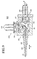
- Figure 9 is a cross-sectional view of the configuration of an optical module 300 according to still another preferred embodiment of the present invention.
- the optical module 300 does not have the first slider 123. Instead, the second attachment section (112) can slidably move with respect to the main housing 110, allowing the position of the light-emitting component 130 to be moved in the X direction (vertically with respect to Figure 9) and the Y direction (normal to the page on which Figure 9 is drawn).
- positional adjustment in the X and Y directions can be done using the light-emitting component 130
- positional adjustment in the Z direction can be done using the second slider 124.
- Figure 10 is a cross-sectional view of the configuration of an optical module 400 according to still another preferred embodiment of the present invention.
- the optical module 400 differs from the optical module 300 of Figure 9 in that the fiber support component 120 is inserted at a predetermined tilt to the straight line between the first attachment section (111) and the second attachment section (112). That is, in the case of the optical module 400, the optical fiber 121 can be affixed at a predetermined tilt to the straight line. This is done so that when the optical fiber is terminated at an inclined angle to the optical axis rather than perpendicular thereto, in order to reduce the effects of reflection at the terminal portion of the optical fiber 121, the effect of the inclination can be compensated to efficiently couple the optical fiber 121 to the light-emitting component 130. An efficient coupling can be ensured by setting the tilt of the optical fiber 121 at no more than 5 degrees.
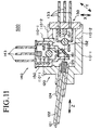
- Figure 11 is a cross-sectional view of the configuration of an optical module 500 according to still another preferred embodiment of the present invention.
- the optical module 500 differs from the optical module 400 of Figure 10 in that the main housing 110 is comprised of two portions, 110-1 and 110-2, which can be mutually slidably moved in the X direction (vertically with respect to Figure 11) and the Y direction (normal to the page on which Figure 11 is drawn).
- the optical module 500 positional adjustment in the X and Y directions is done using the two main housing portions 110-1 and 110-2, and positional adjustment in the Z direction is done using the second slider 124.
- the third attachment section 113 is described as being provided at an angle of 90 degrees to a straight line 110a connecting the first attachment section 111 and the second attachment section 112 (see Figure 2), with the first optical filter 161 being maintained at an angle of 45 degrees to the line 110a, so long as the latter angle is half the former angle, the respective angles do not have to be 90 degrees and 45 degrees.
Landscapes
- Physics & Mathematics (AREA)
- General Physics & Mathematics (AREA)
- Optics & Photonics (AREA)
- Optical Couplings Of Light Guides (AREA)
Applications Claiming Priority (2)
| Application Number | Priority Date | Filing Date | Title |
|---|---|---|---|
| JP2004008495 | 2004-01-15 | ||
| JP2004008495A JP2005202156A (ja) | 2004-01-15 | 2004-01-15 | 光モジュール |
Publications (2)
| Publication Number | Publication Date |
|---|---|
| EP1555554A1 true EP1555554A1 (de) | 2005-07-20 |
| EP1555554A8 EP1555554A8 (de) | 2005-11-02 |
Family
ID=34616899
Family Applications (1)
| Application Number | Title | Priority Date | Filing Date |
|---|---|---|---|
| EP04255768A Withdrawn EP1555554A1 (de) | 2004-01-15 | 2004-09-22 | Optisches Modul für ein bidirektionales Kommunikationssystem |
Country Status (5)
| Country | Link |
|---|---|
| US (1) | US7125174B2 (de) |
| EP (1) | EP1555554A1 (de) |
| JP (1) | JP2005202156A (de) |
| CN (1) | CN1641393A (de) |
| TW (1) | TWI355522B (de) |
Families Citing this family (8)
| Publication number | Priority date | Publication date | Assignee | Title |
|---|---|---|---|---|
| JP5144498B2 (ja) * | 2006-04-06 | 2013-02-13 | 日本電信電話株式会社 | 一心双方向光送受信モジュール及びその製造方法 |
| JP2008051698A (ja) * | 2006-08-25 | 2008-03-06 | Yokogawa Electric Corp | 双方向光モジュールおよびこれを用いた光パルス試験器 |
| JP4253027B2 (ja) * | 2006-11-21 | 2009-04-08 | 古河電気工業株式会社 | 光モジュール |
| US20100252856A1 (en) * | 2009-01-28 | 2010-10-07 | Coretek Opto Corp. | Header structure of opto-electronic element and opto-electronic element using the same |
| US8545112B2 (en) * | 2011-09-14 | 2013-10-01 | Ezconn Corporation | Main housing for optical sub-assembly for transceivers |
| CN104062722A (zh) * | 2014-05-30 | 2014-09-24 | 江苏飞格光电有限公司 | 低串扰同波长波分复用光收发一体单纤双向器件 |
| JP6494093B2 (ja) * | 2015-02-23 | 2019-04-03 | 住友電工デバイス・イノベーション株式会社 | 光モジュール |
| CN112639447B (zh) * | 2018-08-27 | 2023-10-13 | 西铁城时计株式会社 | 光检测模块以及光检测装置 |
Citations (6)
| Publication number | Priority date | Publication date | Assignee | Title |
|---|---|---|---|---|
| EP0715195A1 (de) * | 1994-12-02 | 1996-06-05 | Mitsubishi Denki Kabushiki Kaisha | Optisches Halbleitermodul |
| JP2002296456A (ja) * | 2001-03-29 | 2002-10-09 | Kyocera Corp | 送受信モジュール |
| JP2003075687A (ja) * | 2001-08-30 | 2003-03-12 | Kyocera Corp | 光デバイス |
| WO2003029857A1 (en) * | 2001-09-28 | 2003-04-10 | Corning Incorporated | Optical signal device |
| JP3095902U (ja) * | 2002-02-21 | 2003-08-29 | 旺▲らい▼科技股▲ふん▼有限公司 | 光ファイバー通信システムで使われる光サブアセンブリーモジュール |
| JP2003255196A (ja) * | 2002-02-27 | 2003-09-10 | Kyocera Corp | 光モジュール及びその組立方法 |
Family Cites Families (16)
| Publication number | Priority date | Publication date | Assignee | Title |
|---|---|---|---|---|
| JPS61156208A (ja) | 1984-12-28 | 1986-07-15 | Fujitsu Ltd | 波長選択素子及び波長選択器 |
| US5026134A (en) | 1988-03-01 | 1991-06-25 | Kabushiki Kaisha Toshiba | Optical communication apparatus with base for fixing elements |
| US4904043A (en) | 1988-06-15 | 1990-02-27 | American Telephone And Telegraph Company, At&T Bell Laboratories | Optical data link dual wavelength coupler |
| DE4136893A1 (de) | 1991-11-09 | 1993-05-13 | Ant Nachrichtentech | Optische sende- und empfangsanordnung |
| JP3095902B2 (ja) | 1992-08-26 | 2000-10-10 | イビデン株式会社 | カルボキシル基を導入した光ファイバーの製造方法 |
| JPH06160674A (ja) | 1992-11-19 | 1994-06-07 | Hitachi Ltd | 光電子装置 |
| DE59310297D1 (de) | 1993-09-15 | 2002-09-05 | Infineon Technologies Ag | Sende- und Empfangsmodul für eine bidirektionale optische Mehrkanal-Übertragung |
| EP0706069B1 (de) * | 1994-10-06 | 2003-04-02 | Infineon Technologies AG | Sende- und Empfangsmodul für eine bidirektionale optische Nachrichten- und Signalübertragung |
| EP1082632A1 (de) * | 1998-04-30 | 2001-03-14 | Siemens Aktiengesellschaft | Bidirektionales optisches modul für mehrkanal-anwendung |
| JP3684305B2 (ja) * | 1998-09-17 | 2005-08-17 | 日本オプネクスト株式会社 | 半導体レーザ結合装置および半導体受光装置 |
| US6652158B2 (en) * | 2000-09-05 | 2003-11-25 | Optical Zonu Corporation | Optical networking unit employing optimized optical packaging |
| JP2003095902A (ja) | 2001-09-27 | 2003-04-03 | Hoyu Co Ltd | 毛髪化粧料組成物 |
| US7085007B2 (en) | 2002-03-20 | 2006-08-01 | Eastman Kodak Company | Digital color image processing method |
| JP2003279808A (ja) | 2002-03-25 | 2003-10-02 | Matsushita Electric Ind Co Ltd | 光送受信モジュール |
| DE60311615T2 (de) | 2002-08-23 | 2007-11-22 | Organo Corp. | Verfahren zum Packen von kondensaten Entsalzungsvorrichtungen mit Ionenaustauscherharzen |
| US20040218857A1 (en) * | 2003-04-01 | 2004-11-04 | Chen-Hung Hung | Duplex optical transceiver module |
-
2004
- 2004-01-15 JP JP2004008495A patent/JP2005202156A/ja active Pending
- 2004-07-07 US US10/885,105 patent/US7125174B2/en not_active Expired - Fee Related
- 2004-09-22 EP EP04255768A patent/EP1555554A1/de not_active Withdrawn
- 2004-11-25 CN CN200410096213.5A patent/CN1641393A/zh active Pending
- 2004-12-27 TW TW093140732A patent/TWI355522B/zh not_active IP Right Cessation
Patent Citations (6)
| Publication number | Priority date | Publication date | Assignee | Title |
|---|---|---|---|---|
| EP0715195A1 (de) * | 1994-12-02 | 1996-06-05 | Mitsubishi Denki Kabushiki Kaisha | Optisches Halbleitermodul |
| JP2002296456A (ja) * | 2001-03-29 | 2002-10-09 | Kyocera Corp | 送受信モジュール |
| JP2003075687A (ja) * | 2001-08-30 | 2003-03-12 | Kyocera Corp | 光デバイス |
| WO2003029857A1 (en) * | 2001-09-28 | 2003-04-10 | Corning Incorporated | Optical signal device |
| JP3095902U (ja) * | 2002-02-21 | 2003-08-29 | 旺▲らい▼科技股▲ふん▼有限公司 | 光ファイバー通信システムで使われる光サブアセンブリーモジュール |
| JP2003255196A (ja) * | 2002-02-27 | 2003-09-10 | Kyocera Corp | 光モジュール及びその組立方法 |
Non-Patent Citations (3)
| Title |
|---|
| PATENT ABSTRACTS OF JAPAN vol. 2003, no. 02 5 February 2003 (2003-02-05) * |
| PATENT ABSTRACTS OF JAPAN vol. 2003, no. 07 3 July 2003 (2003-07-03) * |
| PATENT ABSTRACTS OF JAPAN vol. 2003, no. 12 5 December 2003 (2003-12-05) * |
Also Published As
| Publication number | Publication date |
|---|---|
| JP2005202156A (ja) | 2005-07-28 |
| TWI355522B (en) | 2012-01-01 |
| US7125174B2 (en) | 2006-10-24 |
| US20050157988A1 (en) | 2005-07-21 |
| EP1555554A8 (de) | 2005-11-02 |
| TW200527021A (en) | 2005-08-16 |
| CN1641393A (zh) | 2005-07-20 |
Similar Documents
| Publication | Publication Date | Title |
|---|---|---|
| US10754107B2 (en) | Coupling device having a structured reflective surface of stamped malleable metal for coupling input/output of an optical fiber | |
| US7399125B1 (en) | Lens array with integrated folding mirror | |
| EP3146372B1 (de) | Sichtbasierte passive ausrichtung einer glasfaserunterbaugruppe an einer opto-elektronischen vorrichtung | |
| CN109073844B (zh) | 光学子组件与光电器件的光学对准 | |
| US7441965B2 (en) | Connector | |
| US6453091B2 (en) | Optical system unit for optical transceiver | |
| US6236477B1 (en) | Optical transmission and receiving module | |
| US20190391345A1 (en) | Coupling device having a stamped structured surface for routing optical data signals | |
| JP3850743B2 (ja) | 光通信モジュール、および光ファイバと光通信モジュールとの光学的結合構造 | |
| US20060051033A1 (en) | Optical transmitter and receiver module | |
| US7403716B2 (en) | Optical module for bi-directional communication system | |
| US6854897B2 (en) | Ferrule part and optical communications module | |
| EP1555554A1 (de) | Optisches Modul für ein bidirektionales Kommunikationssystem | |
| JP4433730B2 (ja) | 光フィルタ保持部材及び光送受信モジュール | |
| US7099536B1 (en) | Single lens system integrating both transmissive and reflective surfaces for light focusing to an optical fiber and light reflection back to a monitor photodetector | |
| JP2005352256A (ja) | 一心双方向光送受信モジュール用光部品及び一心双方向光送受信モジュール | |
| US20040223705A1 (en) | Bidirectional transmitting and receiving device | |
| JP3096714U (ja) | 光信号のデュプレックス式送受信モジュール | |
| JPH10111438A (ja) | 光送受信装置 | |
| WO2002093224A1 (en) | Optical part, sleeve for optical module, receiving module, optical communication module, and method of manufacturing optical part | |
| JP2008083280A (ja) | 一心双方向送受信モジュール | |
| JP2011128576A (ja) | 単芯双方向光トランシーバーモジュール |
Legal Events
| Date | Code | Title | Description |
|---|---|---|---|
| PUAI | Public reference made under article 153(3) epc to a published international application that has entered the european phase |
Free format text: ORIGINAL CODE: 0009012 |
|
| AK | Designated contracting states |
Kind code of ref document: A1 Designated state(s): AT BE BG CH CY CZ DE DK EE ES FI FR GB GR HU IE IT LI LU MC NL PL PT RO SE SI SK TR |
|
| AX | Request for extension of the european patent |
Extension state: AL HR LT LV MK |
|
| RIN1 | Information on inventor provided before grant (corrected) |
Inventor name: HANASHIMA,NAOKI Inventor name: KINERI;TOHRU Inventor name: HATA,KENJIRO Inventor name: SEKIJIMA,MAKOTO Inventor name: LO,ADRIAN |
|
| RIN1 | Information on inventor provided before grant (corrected) |
Inventor name: HANASHIMA, NAOKI Inventor name: KINERI, TOHRU Inventor name: HATA, KENJIRO Inventor name: SEKIJIMA, MAKOTO Inventor name: LO, ADRIAN |
|
| AKX | Designation fees paid |
Designated state(s): AT BE BG CH CY CZ DE DK EE ES FI FR GB GR HU IE IT LI LU MC NL PL PT RO SE SI SK TR |
|
| STAA | Information on the status of an ep patent application or granted ep patent |
Free format text: STATUS: THE APPLICATION IS DEEMED TO BE WITHDRAWN |
|
| 18D | Application deemed to be withdrawn |
Effective date: 20060430 |