EP1555466B1 - Verfahren zum Verdicken eines Blechs, sowie aus einem solchen Blech bestehende Flachdichtung - Google Patents
Verfahren zum Verdicken eines Blechs, sowie aus einem solchen Blech bestehende Flachdichtung Download PDFInfo
- Publication number
- EP1555466B1 EP1555466B1 EP04029041A EP04029041A EP1555466B1 EP 1555466 B1 EP1555466 B1 EP 1555466B1 EP 04029041 A EP04029041 A EP 04029041A EP 04029041 A EP04029041 A EP 04029041A EP 1555466 B1 EP1555466 B1 EP 1555466B1
- Authority
- EP
- European Patent Office
- Prior art keywords
- sheet
- region
- greater thickness
- bead
- thickness
- Prior art date
- Legal status (The legal status is an assumption and is not a legal conclusion. Google has not performed a legal analysis and makes no representation as to the accuracy of the status listed.)
- Revoked
Links
- 238000000034 method Methods 0.000 title claims abstract description 17
- 239000002184 metal Substances 0.000 title abstract description 7
- 230000008719 thickening Effects 0.000 title description 4
- 238000007789 sealing Methods 0.000 title description 3
- 239000000463 material Substances 0.000 claims description 6
- 238000004513 sizing Methods 0.000 claims description 3
- 238000005096 rolling process Methods 0.000 claims description 2
- 239000011324 bead Substances 0.000 claims 7
- 238000010030 laminating Methods 0.000 abstract 1
- 239000007787 solid Substances 0.000 abstract 1
- 238000002485 combustion reaction Methods 0.000 description 6
- 230000006835 compression Effects 0.000 description 1
- 238000007906 compression Methods 0.000 description 1
- 230000008878 coupling Effects 0.000 description 1
- 238000010168 coupling process Methods 0.000 description 1
- 238000005859 coupling reaction Methods 0.000 description 1
- 230000007547 defect Effects 0.000 description 1
- 238000010586 diagram Methods 0.000 description 1
- 238000009826 distribution Methods 0.000 description 1
- 238000004049 embossing Methods 0.000 description 1
- 239000012530 fluid Substances 0.000 description 1
- 239000011888 foil Substances 0.000 description 1
- 239000011159 matrix material Substances 0.000 description 1
- 125000006850 spacer group Chemical group 0.000 description 1
Images

Classifications
-
- F—MECHANICAL ENGINEERING; LIGHTING; HEATING; WEAPONS; BLASTING
- F16—ENGINEERING ELEMENTS AND UNITS; GENERAL MEASURES FOR PRODUCING AND MAINTAINING EFFECTIVE FUNCTIONING OF MACHINES OR INSTALLATIONS; THERMAL INSULATION IN GENERAL
- F16J—PISTONS; CYLINDERS; SEALINGS
- F16J15/00—Sealings
- F16J15/02—Sealings between relatively-stationary surfaces
- F16J15/06—Sealings between relatively-stationary surfaces with solid packing compressed between sealing surfaces
- F16J15/08—Sealings between relatively-stationary surfaces with solid packing compressed between sealing surfaces with exclusively metal packing
- F16J15/0818—Flat gaskets
-
- B—PERFORMING OPERATIONS; TRANSPORTING
- B21—MECHANICAL METAL-WORKING WITHOUT ESSENTIALLY REMOVING MATERIAL; PUNCHING METAL
- B21D—WORKING OR PROCESSING OF SHEET METAL OR METAL TUBES, RODS OR PROFILES WITHOUT ESSENTIALLY REMOVING MATERIAL; PUNCHING METAL
- B21D22/00—Shaping without cutting, by stamping, spinning, or deep-drawing
- B21D22/02—Stamping using rigid devices or tools
- B21D22/04—Stamping using rigid devices or tools for dimpling
-
- F—MECHANICAL ENGINEERING; LIGHTING; HEATING; WEAPONS; BLASTING
- F16—ENGINEERING ELEMENTS AND UNITS; GENERAL MEASURES FOR PRODUCING AND MAINTAINING EFFECTIVE FUNCTIONING OF MACHINES OR INSTALLATIONS; THERMAL INSULATION IN GENERAL
- F16J—PISTONS; CYLINDERS; SEALINGS
- F16J15/00—Sealings
- F16J15/02—Sealings between relatively-stationary surfaces
- F16J15/06—Sealings between relatively-stationary surfaces with solid packing compressed between sealing surfaces
- F16J15/08—Sealings between relatively-stationary surfaces with solid packing compressed between sealing surfaces with exclusively metal packing
- F16J15/0818—Flat gaskets
- F16J15/0825—Flat gaskets laminated
-
- F—MECHANICAL ENGINEERING; LIGHTING; HEATING; WEAPONS; BLASTING
- F16—ENGINEERING ELEMENTS AND UNITS; GENERAL MEASURES FOR PRODUCING AND MAINTAINING EFFECTIVE FUNCTIONING OF MACHINES OR INSTALLATIONS; THERMAL INSULATION IN GENERAL
- F16J—PISTONS; CYLINDERS; SEALINGS
- F16J15/00—Sealings
- F16J15/02—Sealings between relatively-stationary surfaces
- F16J15/06—Sealings between relatively-stationary surfaces with solid packing compressed between sealing surfaces
- F16J15/08—Sealings between relatively-stationary surfaces with solid packing compressed between sealing surfaces with exclusively metal packing
- F16J15/0818—Flat gaskets
- F16J2015/085—Flat gaskets without fold over
Definitions
- the present invention relates to a method for obtaining an excess thickness on a sheet according to the preamble of claim 1, and to a cylinder head gasket incorporating said sheet.
- a cylinder head gasket 10 used to seal between an engine block and a cylinder head.
- a cylinder head gasket generally has the shape of the engine block, in particular rectangular, and comprises a plurality of openings 12, making it possible to ensure continuity between cavities or ducts arranged on the one hand in the engine block, and on the other part in the breech.
- the cylinder head gasket must ensure a good seal between the ducts between them and between the ducts and the outside despite the geometrical defects of the surfaces in contact with the engine block and the cylinder head and the temperature variations.
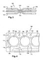
- a cylinder head gasket 10 generally comprises a plurality of stacked sheets or sheets, in particular two active outer plates 14, between which an intermediate plate 16 is arranged. At least one of the outer plates has a rib 18 around the openings that may coincide with the chambers of the cylinder. combustion, close to said openings, oriented towards the inside of the seal, in order to obtain a deformable zone making it possible to compensate for the deformations of the seal.
- ribs 18 are provided on the two outer plates 14, the projecting portions of said ribs 18 are arranged facing each other and oriented toward each other or in opposition.
- the intermediate sheet generally comprises zones of extra thickness, especially around the openings likely to coincide with the combustion chambers and / or periphery.
- the zones of extra thickness are obtained by the addition of elements, in particular a shim 20, called a stopper, at the periphery of the openings provided for the combustion chambers, arranged end to end with the intermediate plate 16 and having a thickness greater than said sheet 16 or a foil 22 attached to a part of the surface of the intermediate sheet 16.
- elements in particular a shim 20, called a stopper, at the periphery of the openings provided for the combustion chambers, arranged end to end with the intermediate plate 16 and having a thickness greater than said sheet 16 or a foil 22 attached to a part of the surface of the intermediate sheet 16.
- Another solution is to obtain the areas of excess thickness by stamping that is to say by deforming the intermediate sheet so as to flow the material from areas of lesser thickness to the areas of extra thickness.
- the document JP-2001295933 describes a sheet comprising an extra thickness obtained by stamping.
- the present invention aims at overcoming the drawbacks of the prior art by proposing a new process for obtaining an excess thickness on a sheet capable of being integrated into a joint, in particular a head gasket.
- the subject of the invention is a process for obtaining an excess thickness at the level of the face of a sheet capable of being incorporated in a joint, characterized in that it consists in performing a ribbing operation. deforming said sheet to form at least one rib and a sizing operation of flattening said rib so as to form an area of extra thickness.
- This technique makes it possible to obtain an area of excess thickness without the addition of an insert and does not require high power tooling.
- a cylinder head gasket according to the invention is defined in claims 6 and 7.
- the sheet 30 is subjected to a stamping operation of plastically deforming said sheet between two dies.
- This optional embossing operation provides a vertical offset 32. It is not more detailed because it is within the reach of those skilled in the art and is not the essential element of the invention.
- the sheet 30 undergoes a ribbing operation of deforming said sheet 30 to form at least one rib 34 and a calibration operation consisting of flattening said ribbed portion so as to obtain an area of extra thickness 36 with a precise height so as to improve the distribution of the contact pressures and thus the sealing.
- Flattening means deformation of the rib so as to reduce its height.
- the rib 34 is calibrated with a force such that the zone of extra thickness forms a free stop, that is to say substantially no deformable, able to withstand the constraints it will support in its application.
- the rib is calibrated with a force greater than or equal to those it will support in its application, and preferably with a force corresponding to those it will support in its application with a margin of safety.
- the rib is completely flattened, it does not return to the initial state as illustrated by the Figure 2A but still retains at the rib 34 a zone of overthickness 36.
- the ribbing operation is carried out along a path corresponding to the location of the future zone (s) of extra thickness, the ribs may be continuous (s) or discontinuous (s).
- This operation can be done with a tool whose punch may have a height and a variable width depending on the location. It may be the same for the corresponding matrix.
- the calibration operation can be obtained by planing and the height of the extra thickness obtained can vary from one point to another, in particular to form a so-called 3D stopper.
- the sheet undergoes a rolling operation during the ribbing phase, the thickness of the sheet being less than the clearance provided between the die and the punch.
- the material is stretched and deformed in the plastic area at the flanks of the rib.
- a cylinder head gasket 100 incorporating at least one sheet with at least one thickened area obtained from the method of the invention.
- the cylinder head gasket 100 comprises a plurality of stacked sheets or sheets, in particular two active outer plates 102, between which an intermediate plate 104 is placed and a plurality of openings, in particular at least one opening 106 capable of coinciding with a chamber of FIG. combustion, fluid passages 108 and screw passages 110 for fastening means.
- At least one of the outer plates 102 has a rib 112 around the openings likely to coincide with the combustion chambers, close to said openings, oriented towards the inside of the seal, in order to obtain a deformable zone making it possible to compensate for the deformations. of the seal.
- ribs 112 are provided on the two outer plates 102, the projecting portions of said ribs 112 are disposed facing each other and oriented towards each other or in opposition.
- the intermediate sheet 104 comprises at least one zone of extra thickness obtained from the method of the invention.
- the intermediate sheet 104 comprises a first thickening zone 114 around at least one opening 106 capable of coupling with a combustion chamber 106 and / or a second thickening zone 116 at the periphery of the intermediate sheet.
- the intermediate plate 104 may comprise extra thicknesses around the openings 106, 108 and 110.
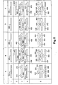
- a sheet 200 undergoes a ribbing operation so as to obtain two ribs 210 and 212 and a calibration operation so as to transform said ribs into thickening zones 220 and 222.
- the seal comprises in addition to the sheet 200 two sheets 230 and 232 carrying ribs 240 facing outwards, one of the ribs 240 being able to bear against the face of the sheet 200 carrying the zones of thickness 220 and 222, between said zones.
- the variant of the column B comprises an intermediate sheet 300 with an offset 305 obtained by stamping.
- the intermediate sheet 300 undergoes a ribbing operation so as to obtain two ribs 310 and 312, on either side of the offset 305 and a calibration operation so as to transform said ribs into zones of increased thickness 320 and 322.
- the intermediate sheet 300 is disposed between two outer sheets 330 and 332 each comprising a rib 340 capable of bearing against the intermediate plate 300 to the right of the offset 305
- the variant of the column C resumes an arrangement close to that of the column A, the identical elements bearing the same references increased by 200, with a single sheet 430.
- the variant illustrated in column D comprises an intermediate sheet 500 which has been subjected to a ribbing operation so as to obtain two ribs 510 and 512 oriented in opposition and a calibration operation so as to convert the ribs into zones of extra thickness 520 and 522.
- the intermediate sheet 500 is disposed between two outer sheets 530 and 532 each comprising a rib 540 capable of bearing against said intermediate sheet 500.
- the variant of the column E comprises a spacer plate 600 with an offset 605 obtained by stamping.
- This plate 600 undergoes a ribbing operation so as to obtain a rib 610 at the right of the offset 605 and a calibration operation so as to transform the rib 610 into a thickened area 620.
- the intermediate plate 600 is disposed between two outer plates 630 and 632 each comprising a rib 640 capable of bearing against said intermediate plate 600.
- zones of excess thickness may be provided on any or all of the sheets forming the head gasket.
- this plate with localized thickness is not limited to the application described and may be suitable for all types of metal joints requiring extra thickness at a sheet.
Landscapes
- Engineering & Computer Science (AREA)
- General Engineering & Computer Science (AREA)
- Mechanical Engineering (AREA)
- Gasket Seals (AREA)
- Laminated Bodies (AREA)
- Lining Or Joining Of Plastics Or The Like (AREA)
- Diaphragms For Electromechanical Transducers (AREA)
- Lubricants (AREA)
- Orthopedics, Nursing, And Contraception (AREA)
- Shaping Of Tube Ends By Bending Or Straightening (AREA)
Claims (7)
- Verfahren zum Erhalt einer Überdicke in Höhe der Fläche eines Blechs (30), das in eine Dichtung eingebaut werden kann, dadurch gekennzeichnet, dass es darin besteht, einen Rippenbildungsvorgang durchzuführen, der darin besteht, das Blech (30) zu verformen, um mindestens eine Rippe (34) zu bilden, und einen Kalibrierungsvorgang durchzuführen, der darin besteht, die Rippe (34) so abzuflachen, dass eine Überdickenzone (36) geformt wird.
- Verfahren nach Anspruch 1, dadurch gekennzeichnet, dass die Rippe (34) mit einer solchen Kraft kalibriert wird, dass sie einen nicht verformbaren Anschlag bildet, der den Beanspruchungen widerstehen kann, die die Überdickenzone (36) bei ihrer Nutzung erfährt.
- Verfahren nach Anspruch 1 oder 2, dadurch gekennzeichnet, dass das Blech (30) während der Rippenbildungsphase einem Walzvorgang unterzogen wird, um nach dem Kalibrierungsvorgang eine Überdickenzone zu erhalten, die einen nicht verformbaren Anschlag bildet, der den Beanspruchungen widerstehen kann, die die Überdickenzone (36) bei ihrer Nutzung erfährt.
- Verfahren nach einem der vorhergehenden Ansprüche, dadurch gekennzeichnet, dass die Höhe der Überdickenzone (36) von einem Punkt zu einem anderen variieren kann.
- Verfahren nach einem der vorhergehenden Ansprüche, dadurch gekennzeichnet, dass es vorab darin besteht, einen Vorgang des Prägens durchzuführen, um einen Versatz (32) zu erhalten.
- Zylinderkopfdichtung, die ein aktives Blech und ein Zwischenblech umfasst, wobei das aktive Blech mindestens eine Rippe aufweist, die gegen eine Fläche des Zwischenblechs in Anlage kommen kann, und das Zwischenblech auf dieser gleichen Fläche mindestens eine Überdickenzone mit mindestens einer kalibrierten Rippe aufweist, die durch ein Ziehen und dann Abflachen des Materials erhalten wird, um einen nicht verformbaren Anschlag zu erhalten.
- Zylinderkopfdichtung, die mindestens zwei aktive Bleche umfasst, zwischen denen mindestens ein Zwischenblech angeordnet ist, wobei die aktiven Bleche je mindestens eine Rippe aufweisen, die gegen das Zwischenblech in Anlage kommen kann, und das Zwischenblech auf jeder Fläche mindestens eine Überdickenzone aufweist, wobei jede Überdickenzone mindestens eine kalibrierte Rippe aufweist, die durch ein Ziehen und dann Abflachen des Materials erhalten wird, um einen nicht verformbaren Anschlag zu erhalten.
Applications Claiming Priority (2)
| Application Number | Priority Date | Filing Date | Title |
|---|---|---|---|
| FR0450071A FR2864914B1 (fr) | 2004-01-13 | 2004-01-13 | Procede d'obtention d'une surepaisseur sur une tole, tole ainsi obtenue et joint incorporant ladite tole |
| FR0450071 | 2004-01-13 |
Publications (2)
| Publication Number | Publication Date |
|---|---|
| EP1555466A1 EP1555466A1 (de) | 2005-07-20 |
| EP1555466B1 true EP1555466B1 (de) | 2008-07-09 |
Family
ID=34610799
Family Applications (1)
| Application Number | Title | Priority Date | Filing Date |
|---|---|---|---|
| EP04029041A Revoked EP1555466B1 (de) | 2004-01-13 | 2004-12-08 | Verfahren zum Verdicken eines Blechs, sowie aus einem solchen Blech bestehende Flachdichtung |
Country Status (5)
| Country | Link |
|---|---|
| EP (1) | EP1555466B1 (de) |
| JP (1) | JP2005201448A (de) |
| AT (1) | ATE400753T1 (de) |
| DE (1) | DE602004014891D1 (de) |
| FR (1) | FR2864914B1 (de) |
Families Citing this family (2)
| Publication number | Priority date | Publication date | Assignee | Title |
|---|---|---|---|---|
| FR2875570B1 (fr) * | 2004-09-21 | 2007-02-16 | Meillor Sa Sa | Joint comprenant au moins une nervure incorporant un limiteur d'ecrasement |
| DE202016104243U1 (de) * | 2016-08-02 | 2017-11-03 | Reinz-Dichtungs-Gmbh | Flachdichtung sowie Verbrennungsmotor mit einer derartigen Flachdichtung |
Family Cites Families (4)
| Publication number | Priority date | Publication date | Assignee | Title |
|---|---|---|---|---|
| FR2681378B1 (fr) * | 1991-09-13 | 1995-02-24 | Meillor Sa | Procede de fabrication d'un joint d'etancheite et le joint obtenu. |
| FR2724439B1 (fr) * | 1994-09-13 | 1996-10-25 | Curty Payen Sa | Joint metal-elastomere, notamment joint d'etancheite plat |
| JP2001295933A (ja) * | 2000-04-17 | 2001-10-26 | Taiho Kogyo Co Ltd | 金属ガスケット |
| DE10106048A1 (de) * | 2001-02-09 | 2002-09-19 | Federal Mogul Sealing Sys Spa | Ein- oder mehrlagige Flachdichtung |
-
2004
- 2004-01-13 FR FR0450071A patent/FR2864914B1/fr not_active Expired - Fee Related
- 2004-12-08 DE DE602004014891T patent/DE602004014891D1/de not_active Expired - Lifetime
- 2004-12-08 EP EP04029041A patent/EP1555466B1/de not_active Revoked
- 2004-12-08 AT AT04029041T patent/ATE400753T1/de not_active IP Right Cessation
-
2005
- 2005-01-12 JP JP2005005295A patent/JP2005201448A/ja active Pending
Also Published As
| Publication number | Publication date |
|---|---|
| JP2005201448A (ja) | 2005-07-28 |
| ATE400753T1 (de) | 2008-07-15 |
| DE602004014891D1 (de) | 2008-08-21 |
| FR2864914B1 (fr) | 2007-02-23 |
| FR2864914A1 (fr) | 2005-07-15 |
| EP1555466A1 (de) | 2005-07-20 |
Similar Documents
| Publication | Publication Date | Title |
|---|---|---|
| EP1637780B9 (de) | Dichtung mit mindestens einem Wulst mit integriertem Begrenzer | |
| FR2804480A1 (fr) | Procede de fixation d'au moins un palier dans un logement et agencement de palier ainsi realise | |
| EP1521019B1 (de) | Mehrlagendichtung mit mindestens einem Stutzelement | |
| EP2683966B1 (de) | Semigewellte dichtung | |
| EP1555466B1 (de) | Verfahren zum Verdicken eines Blechs, sowie aus einem solchen Blech bestehende Flachdichtung | |
| EP1430241B1 (de) | Zylinderkopfdichtung mit einem durch heften verbundenen, sich von rand zu rand erstreckenden anschlagring | |
| EP1536166B1 (de) | Dichtung mit einem verdickten Blech | |
| EP1693606B1 (de) | Metallische Dichtung mit einer Verdickung in Form von unterbrochenen Vorsprüngen | |
| EP1541254B1 (de) | Verfahren zum Herstellen eines Bleches mit vergrösserter Wanddicke sowie Dichtung aus einem solchen Blech | |
| FR2699600A1 (fr) | Segments de piston, procédé pour la fabrication et assemblage d'un piston les utilisant. | |
| JP5932213B2 (ja) | シリンダヘッドガスケットの製造方法 | |
| FR2803230A1 (fr) | Dispositif et procede de formage d'une tole permettant de limiter le retour elastique de la tole apres formage et utilisation | |
| EP1693605B1 (de) | Metallische Dichtung mit einer Verdickung in Form eines mäanderförmigen Vorsprungs | |
| FR2875423A1 (fr) | Procede de fabrication d'une feuille metallique avec au moins une zone de surepaisseur integree pour joint metallique serre, notamment un joint de culasse et feuille obtenue | |
| EP0667453B1 (de) | Zahnrad für Zahnradpumpen und Herstellungsverfahren | |
| FR2669678A1 (fr) | Joint de culasse. | |
| FR2681378A1 (fr) | Procede de fabrication d'un joint d'etancheite et le joint obtenu. | |
| EP1536165A1 (de) | Passender Anschlagring und damit ausgestattete Zylinderkopfdichtung | |
| FR2803893A1 (fr) | Procede de realisation d'une cale dite stoppeur sur un joint, notamment sur un joint de culasse, et joint ainsi obtenu | |
| JP5023102B2 (ja) | 金属製ガスケット及びその製造方法 | |
| FR2827639A1 (fr) | Joint de culasse comprenant un stoppeur bord a bord | |
| FR3125974A1 (fr) | Procédé et dispositif de fabrication de pièce à partir d’une plaque en matériau déformable, en particulier pour un bord d’un élément d’un aéronef. | |
| WO2006018542A1 (fr) | Procédé de fabrication d'une forme d'empreinte en contre depouille sur une partie metallique | |
| JP2002081545A (ja) | ヘッドガスケット | |
| FR2962181A1 (fr) | Joint a procede de fabrication simplifie, de preference pour lanceurs spatiaux |
Legal Events
| Date | Code | Title | Description |
|---|---|---|---|
| PUAI | Public reference made under article 153(3) epc to a published international application that has entered the european phase |
Free format text: ORIGINAL CODE: 0009012 |
|
| 17P | Request for examination filed |
Effective date: 20050421 |
|
| AK | Designated contracting states |
Kind code of ref document: A1 Designated state(s): AT BE BG CH CY CZ DE DK EE ES FI FR GB GR HU IE IS IT LI LT LU MC NL PL PT RO SE SI SK TR |
|
| AX | Request for extension of the european patent |
Extension state: AL BA HR LV MK YU |
|
| AKX | Designation fees paid |
Designated state(s): AT BE BG CH CY CZ DE DK EE ES FI FR GB GR HU IE IS IT LI LT LU MC NL PL PT RO SE SI SK TR |
|
| 17Q | First examination report despatched |
Effective date: 20060713 |
|
| GRAP | Despatch of communication of intention to grant a patent |
Free format text: ORIGINAL CODE: EPIDOSNIGR1 |
|
| RTI1 | Title (correction) |
Free format text: METHOD FOR THICKENING A METAL SHEET AND SEALING GASKET COMPRISING SUCH A METAL SHEET |
|
| GRAS | Grant fee paid |
Free format text: ORIGINAL CODE: EPIDOSNIGR3 |
|
| GRAA | (expected) grant |
Free format text: ORIGINAL CODE: 0009210 |
|
| AK | Designated contracting states |
Kind code of ref document: B1 Designated state(s): AT BE BG CH CY CZ DE DK EE ES FI FR GB GR HU IE IS IT LI LT LU MC NL PL PT RO SE SI SK TR |
|
| REG | Reference to a national code |
Ref country code: GB Ref legal event code: FG4D Free format text: NOT ENGLISH |
|
| REG | Reference to a national code |
Ref country code: CH Ref legal event code: EP |
|
| REF | Corresponds to: |
Ref document number: 602004014891 Country of ref document: DE Date of ref document: 20080821 Kind code of ref document: P |
|
| REG | Reference to a national code |
Ref country code: IE Ref legal event code: FG4D Free format text: LANGUAGE OF EP DOCUMENT: FRENCH |
|
| NLV1 | Nl: lapsed or annulled due to failure to fulfill the requirements of art. 29p and 29m of the patents act | ||
| PG25 | Lapsed in a contracting state [announced via postgrant information from national office to epo] |
Ref country code: LT Free format text: LAPSE BECAUSE OF FAILURE TO SUBMIT A TRANSLATION OF THE DESCRIPTION OR TO PAY THE FEE WITHIN THE PRESCRIBED TIME-LIMIT Effective date: 20080709 Ref country code: PT Free format text: LAPSE BECAUSE OF FAILURE TO SUBMIT A TRANSLATION OF THE DESCRIPTION OR TO PAY THE FEE WITHIN THE PRESCRIBED TIME-LIMIT Effective date: 20081209 Ref country code: IS Free format text: LAPSE BECAUSE OF FAILURE TO SUBMIT A TRANSLATION OF THE DESCRIPTION OR TO PAY THE FEE WITHIN THE PRESCRIBED TIME-LIMIT Effective date: 20081109 Ref country code: NL Free format text: LAPSE BECAUSE OF FAILURE TO SUBMIT A TRANSLATION OF THE DESCRIPTION OR TO PAY THE FEE WITHIN THE PRESCRIBED TIME-LIMIT Effective date: 20080709 Ref country code: ES Free format text: LAPSE BECAUSE OF FAILURE TO SUBMIT A TRANSLATION OF THE DESCRIPTION OR TO PAY THE FEE WITHIN THE PRESCRIBED TIME-LIMIT Effective date: 20081020 |
|
| PLBI | Opposition filed |
Free format text: ORIGINAL CODE: 0009260 |
|
| PG25 | Lapsed in a contracting state [announced via postgrant information from national office to epo] |
Ref country code: SI Free format text: LAPSE BECAUSE OF FAILURE TO SUBMIT A TRANSLATION OF THE DESCRIPTION OR TO PAY THE FEE WITHIN THE PRESCRIBED TIME-LIMIT Effective date: 20080709 Ref country code: FI Free format text: LAPSE BECAUSE OF FAILURE TO SUBMIT A TRANSLATION OF THE DESCRIPTION OR TO PAY THE FEE WITHIN THE PRESCRIBED TIME-LIMIT Effective date: 20080709 Ref country code: AT Free format text: LAPSE BECAUSE OF FAILURE TO SUBMIT A TRANSLATION OF THE DESCRIPTION OR TO PAY THE FEE WITHIN THE PRESCRIBED TIME-LIMIT Effective date: 20080709 Ref country code: BG Free format text: LAPSE BECAUSE OF FAILURE TO SUBMIT A TRANSLATION OF THE DESCRIPTION OR TO PAY THE FEE WITHIN THE PRESCRIBED TIME-LIMIT Effective date: 20081009 |
|
| REG | Reference to a national code |
Ref country code: IE Ref legal event code: FD4D |
|
| 26 | Opposition filed |
Opponent name: ELRING KLINGER AG Effective date: 20090214 |
|
| PG25 | Lapsed in a contracting state [announced via postgrant information from national office to epo] |
Ref country code: IE Free format text: LAPSE BECAUSE OF FAILURE TO SUBMIT A TRANSLATION OF THE DESCRIPTION OR TO PAY THE FEE WITHIN THE PRESCRIBED TIME-LIMIT Effective date: 20080709 Ref country code: EE Free format text: LAPSE BECAUSE OF FAILURE TO SUBMIT A TRANSLATION OF THE DESCRIPTION OR TO PAY THE FEE WITHIN THE PRESCRIBED TIME-LIMIT Effective date: 20080709 Ref country code: DK Free format text: LAPSE BECAUSE OF FAILURE TO SUBMIT A TRANSLATION OF THE DESCRIPTION OR TO PAY THE FEE WITHIN THE PRESCRIBED TIME-LIMIT Effective date: 20080709 |
|
| PLAX | Notice of opposition and request to file observation + time limit sent |
Free format text: ORIGINAL CODE: EPIDOSNOBS2 |
|
| PG25 | Lapsed in a contracting state [announced via postgrant information from national office to epo] |
Ref country code: SK Free format text: LAPSE BECAUSE OF FAILURE TO SUBMIT A TRANSLATION OF THE DESCRIPTION OR TO PAY THE FEE WITHIN THE PRESCRIBED TIME-LIMIT Effective date: 20080709 Ref country code: CZ Free format text: LAPSE BECAUSE OF FAILURE TO SUBMIT A TRANSLATION OF THE DESCRIPTION OR TO PAY THE FEE WITHIN THE PRESCRIBED TIME-LIMIT Effective date: 20080709 Ref country code: RO Free format text: LAPSE BECAUSE OF FAILURE TO SUBMIT A TRANSLATION OF THE DESCRIPTION OR TO PAY THE FEE WITHIN THE PRESCRIBED TIME-LIMIT Effective date: 20080709 |
|
| BERE | Be: lapsed |
Owner name: CARL FREUDENBERG K.G. Effective date: 20081231 |
|
| PG25 | Lapsed in a contracting state [announced via postgrant information from national office to epo] |
Ref country code: MC Free format text: LAPSE BECAUSE OF NON-PAYMENT OF DUE FEES Effective date: 20081231 |
|
| REG | Reference to a national code |
Ref country code: CH Ref legal event code: PL |
|
| GBPC | Gb: european patent ceased through non-payment of renewal fee |
Effective date: 20081208 |
|
| PLBB | Reply of patent proprietor to notice(s) of opposition received |
Free format text: ORIGINAL CODE: EPIDOSNOBS3 |
|
| PG25 | Lapsed in a contracting state [announced via postgrant information from national office to epo] |
Ref country code: BE Free format text: LAPSE BECAUSE OF NON-PAYMENT OF DUE FEES Effective date: 20081231 |
|
| PG25 | Lapsed in a contracting state [announced via postgrant information from national office to epo] |
Ref country code: LI Free format text: LAPSE BECAUSE OF NON-PAYMENT OF DUE FEES Effective date: 20081231 Ref country code: CH Free format text: LAPSE BECAUSE OF NON-PAYMENT OF DUE FEES Effective date: 20081231 |
|
| PG25 | Lapsed in a contracting state [announced via postgrant information from national office to epo] |
Ref country code: GB Free format text: LAPSE BECAUSE OF NON-PAYMENT OF DUE FEES Effective date: 20081208 |
|
| PG25 | Lapsed in a contracting state [announced via postgrant information from national office to epo] |
Ref country code: SE Free format text: LAPSE BECAUSE OF FAILURE TO SUBMIT A TRANSLATION OF THE DESCRIPTION OR TO PAY THE FEE WITHIN THE PRESCRIBED TIME-LIMIT Effective date: 20081009 |
|
| PG25 | Lapsed in a contracting state [announced via postgrant information from national office to epo] |
Ref country code: PL Free format text: LAPSE BECAUSE OF FAILURE TO SUBMIT A TRANSLATION OF THE DESCRIPTION OR TO PAY THE FEE WITHIN THE PRESCRIBED TIME-LIMIT Effective date: 20080709 |
|
| PG25 | Lapsed in a contracting state [announced via postgrant information from national office to epo] |
Ref country code: LU Free format text: LAPSE BECAUSE OF NON-PAYMENT OF DUE FEES Effective date: 20081208 Ref country code: HU Free format text: LAPSE BECAUSE OF FAILURE TO SUBMIT A TRANSLATION OF THE DESCRIPTION OR TO PAY THE FEE WITHIN THE PRESCRIBED TIME-LIMIT Effective date: 20090110 Ref country code: CY Free format text: LAPSE BECAUSE OF FAILURE TO SUBMIT A TRANSLATION OF THE DESCRIPTION OR TO PAY THE FEE WITHIN THE PRESCRIBED TIME-LIMIT Effective date: 20080709 |
|
| PG25 | Lapsed in a contracting state [announced via postgrant information from national office to epo] |
Ref country code: TR Free format text: LAPSE BECAUSE OF FAILURE TO SUBMIT A TRANSLATION OF THE DESCRIPTION OR TO PAY THE FEE WITHIN THE PRESCRIBED TIME-LIMIT Effective date: 20080709 |
|
| PG25 | Lapsed in a contracting state [announced via postgrant information from national office to epo] |
Ref country code: GR Free format text: LAPSE BECAUSE OF FAILURE TO SUBMIT A TRANSLATION OF THE DESCRIPTION OR TO PAY THE FEE WITHIN THE PRESCRIBED TIME-LIMIT Effective date: 20081010 |
|
| PLBP | Opposition withdrawn |
Free format text: ORIGINAL CODE: 0009264 |
|
| PGFP | Annual fee paid to national office [announced via postgrant information from national office to epo] |
Ref country code: FR Payment date: 20110107 Year of fee payment: 7 |
|
| RAP2 | Party data changed (patent owner data changed or rights of a patent transferred) |
Owner name: ELRINGKLINGER AG |
|
| PGFP | Annual fee paid to national office [announced via postgrant information from national office to epo] |
Ref country code: IT Payment date: 20101220 Year of fee payment: 7 |
|
| RDAF | Communication despatched that patent is revoked |
Free format text: ORIGINAL CODE: EPIDOSNREV1 |
|
| REG | Reference to a national code |
Ref country code: DE Ref legal event code: R103 Ref document number: 602004014891 Country of ref document: DE Ref country code: DE Ref legal event code: R064 Ref document number: 602004014891 Country of ref document: DE |
|
| PGFP | Annual fee paid to national office [announced via postgrant information from national office to epo] |
Ref country code: DE Payment date: 20110125 Year of fee payment: 7 |
|
| RDAG | Patent revoked |
Free format text: ORIGINAL CODE: 0009271 |
|
| STAA | Information on the status of an ep patent application or granted ep patent |
Free format text: STATUS: PATENT REVOKED |
|
| 27W | Patent revoked |
Effective date: 20110506 |
|
| REG | Reference to a national code |
Ref country code: DE Ref legal event code: R107 Ref document number: 602004014891 Country of ref document: DE Effective date: 20111103 |