EP1521019B1 - Mehrlagendichtung mit mindestens einem Stutzelement - Google Patents
Mehrlagendichtung mit mindestens einem Stutzelement Download PDFInfo
- Publication number
- EP1521019B1 EP1521019B1 EP04019799A EP04019799A EP1521019B1 EP 1521019 B1 EP1521019 B1 EP 1521019B1 EP 04019799 A EP04019799 A EP 04019799A EP 04019799 A EP04019799 A EP 04019799A EP 1521019 B1 EP1521019 B1 EP 1521019B1
- Authority
- EP
- European Patent Office
- Prior art keywords
- metal sheet
- shim
- inter
- layer metal
- thickness
- Prior art date
- Legal status (The legal status is an assumption and is not a legal conclusion. Google has not performed a legal analysis and makes no representation as to the accuracy of the status listed.)
- Expired - Lifetime
Links
- 230000008719 thickening Effects 0.000 title description 2
- 238000000034 method Methods 0.000 claims abstract description 12
- 238000002485 combustion reaction Methods 0.000 claims abstract description 10
- 239000002184 metal Substances 0.000 claims description 23
- 238000004519 manufacturing process Methods 0.000 claims description 2
- 230000002093 peripheral effect Effects 0.000 claims description 2
- 239000011229 interlayer Substances 0.000 claims 14
- 239000011324 bead Substances 0.000 claims 6
- 125000006850 spacer group Chemical group 0.000 abstract description 6
- 230000015572 biosynthetic process Effects 0.000 abstract 1
- 230000002787 reinforcement Effects 0.000 abstract 1
- 239000011888 foil Substances 0.000 description 5
- 239000012809 cooling fluid Substances 0.000 description 3
- 238000005096 rolling process Methods 0.000 description 3
- 238000003466 welding Methods 0.000 description 3
- 239000000463 material Substances 0.000 description 2
- 238000004080 punching Methods 0.000 description 2
- 238000005520 cutting process Methods 0.000 description 1
- 230000007547 defect Effects 0.000 description 1
- 238000003754 machining Methods 0.000 description 1
- 239000011347 resin Substances 0.000 description 1
- 229920005989 resin Polymers 0.000 description 1
- 238000007650 screen-printing Methods 0.000 description 1
- 238000009827 uniform distribution Methods 0.000 description 1
Images


Classifications
-
- F—MECHANICAL ENGINEERING; LIGHTING; HEATING; WEAPONS; BLASTING
- F16—ENGINEERING ELEMENTS AND UNITS; GENERAL MEASURES FOR PRODUCING AND MAINTAINING EFFECTIVE FUNCTIONING OF MACHINES OR INSTALLATIONS; THERMAL INSULATION IN GENERAL
- F16J—PISTONS; CYLINDERS; SEALINGS
- F16J15/00—Sealings
- F16J15/02—Sealings between relatively-stationary surfaces
- F16J15/06—Sealings between relatively-stationary surfaces with solid packing compressed between sealing surfaces
- F16J15/08—Sealings between relatively-stationary surfaces with solid packing compressed between sealing surfaces with exclusively metal packing
- F16J15/0818—Flat gaskets
- F16J15/0825—Flat gaskets laminated
Definitions
- the present invention relates to a multilayer gasket comprising at least one thicker shim, and more particularly to a multilayer metal gasket.
- a cylinder head gasket is used to seal between an engine block and a cylinder head.
- a cylinder head gasket 10 generally has the shape of the engine block, in particular rectangular, and comprises a plurality of openings, making it possible to ensure continuity between cavities or ducts arranged on the one hand in the engine block, and other part in the breech.
- first openings 12 are provided for the combustion chambers
- second openings 14 for the ducts of the cooling fluid or fluids
- third openings 16 to allow the passage of bolt fixing elements on the engine block, in particular threaded rods.
- the cylinder head gasket must ensure a good seal between the ducts between them and between the ducts and the outside despite the geometric defects of the surfaces in contact with the engine block and the cylinder head and the temperature variations.
- a cylinder head gasket 10 comprises a plurality of stacked sheets or sheets, in particular two active outer plates 18 between which an intermediate sheet 20 is disposed. At least one of the outer plates 18 has a rib 22 around the first openings 12, close to said openings, facing towards the inside of the joint, in order to obtain a zone deformable to compensate for the deformations of the joint.
- ribs 22 are provided on the two outer plates 18, the projecting portions of said ribs are arranged opposite and oriented towards each other or in opposition.
- said gasket 10 comprises a wedge 24 called a stopper disposed at the periphery of the first openings 12 provided for the combustion chambers and edge to edge with the intermediate plate 20.
- This stopper 24 has a thickness slightly greater than the sheet metal insert 20 allowing on the one hand to obtain a higher clamping force around the combustion chambers, and on the other hand, to obtain a pre-stress of at least one of the outer plates 18 reducing the range of movement and the crushing of the ribs.
- the stopper may have a variable thickness to obtain a uniform distribution of the clamping force on the periphery of the openings 12 provided for the combustion chambers.
- the extra thickness is obtained by bringing on the surface of the intermediate sheet 20 a foil 26 or a thin sheet, less than or equal to 0.1 mm thick.
- the extra thickness is obtained by stamping the intermediate sheet 20 to provide a variable thickness.
- This solution is also not satisfactory because the stamping of a sheet to give localized variable thickness is relatively complex and expensive to implement. Moreover, this stamping technique does not make it possible to obtain thicknesses of precise dimensions, unlike the rolling technique.
- the extra thickness is obtained using a resin deposited by screen printing on the intermediate sheet. This solution is also relatively complex and expensive to implement.
- the present invention aims to overcome the drawbacks of the prior art by providing a multilayer gasket with a localized variable thickness thickness sheet metal of simple design whose implementation is easy and relatively less expensive.
- the subject of the invention is a cylinder head gasket with at least one orifice corresponding to a combustion chamber, said gasket comprising a stack of at least one so-called active sheet comprising at least one rib formed around said orifice or said orifice.
- the seal comprising at least one so-called shim allowance arranged in the plane of the intermediate sheet, at the right of the active sheet (s), outside the rib or ribs, said thickening wedge having a thickness such that said wedge is a localized allowance relative to the intermediate sheet, characterized in that the intermediate sheet comprises at least one recess or a housing capable of receiving at least one extra thickness wedge.
- the shim is arranged in a housing formed in the intermediate sheet, the forms of the spacer interminging with those housing that receives it. This arrangement allows a better immobilization of the shim extra thickness.
- the housing is opening.
- This variant has the advantage of simplifying the procedure and to obtain an accurate extra thickness corresponding to the thickness of the shim of extra thickness obtained by rolling.
- the invention also proposes a method for producing an extra thickness in a spacer plate of a cylinder head gasket.
- FIG. 1 On the figure 1 , there is shown a cylinder head gasket 100.
- This type of seal interposed between an engine block and a cylinder head comprises a plurality of openings for ensuring continuity between cavities or ducts in said engine block and said cylinder head. So, the seal of cylinder head 100 must seal between the cavities or ducts between them and with the outside.
- the cylinder head gasket 100 comprises first openings 112 provided for the combustion chambers, second openings 114 provided for conduits or cooling fluids and third openings 116 provided to allow the passage fasteners of the cylinder head on the engine block, including threaded rods.
- This cylinder head gasket 100 comprises a plurality of stacked sheets or sheets, in particular two active outer plates 118 between which an intermediate sheet 120 is disposed. At least one of the outer plates 118 has a rib 122 around the first openings 112, close to said openings. , oriented towards the inside of the seal, in order to obtain a deformable zone making it possible to compensate the deformations of the seal.
- ribs 122 are provided on the two outer plates 118, the projecting portions of said ribs are preferably arranged facing each other and oriented towards each other.
- the rib or ribs 122 define two zones, a first zone inside the rib or ribs and a second zone outside the rib or ribs 122 called non-gas zone.
- said seal 110 comprises a wedge 124 called a stopper, of greater thickness than the intermediate sheet 120, disposed at the periphery of the first openings 112 and edge to edge with the intermediate plate 120.
- the seal 110 comprises at least one shim 130 called extra thickness disposed in the plane of the intermediate sheet 120, to the right of the active sheet or plates 118, outside the rib or ribs, said shim excess thickness having a thickness such that said shim 130 is a localized allowance relative to the intermediate plate 120.
- a portion of the shim 130 is capable of coming into contact with at least a portion of the section of the intermediate plate 120, the corresponding section being at the edge. peripheral of the intermediate sheet, either at the edge of a housing or recess formed in the intermediate sheet.
- part of the shim 130 is able to come into contact with at least one active sheet or is placed between two active plates.
- the shim 130 of extra thickness is disposed in a housing or a recess 128 formed in the intermediate plate 120.
- the shapes of the shim 130 of extra thickness cooperate with those of the housing 128 which receives it in order to limit the relative movements in the plane of the intermediate plate 120.
- the shim 130 is immobilized in translation by the edges of the housing 128 and has a thickness greater than that of a foil 26 of the prior art facilitating its implementation.
- a material removal machining operation to provide a housing or recess is relatively simpler and less expensive to perform than a stamping operation.
- the housing 128 may be non-opening as illustrated on the figure 3 or emerging as shown on the figure 4 .
- This second variant has the advantage of simplifying the procedure and to obtain an accurate extra thickness corresponding to the thickness of the shim 130 of extra thickness obtained by rolling.
- the second variant is illustrated in perspective on the figure 5 .
- the extra thickness generated by the shim 130 makes it possible to reduce the mechanical stresses at the level of the outer plates 118 and to obtain a uniform clamping pressure over the entire surface of the joint.
- the housings 128 made in the intermediate plate 120 are obtained by punching, preferably during the cutting of the openings 112, 114 and 116.
- the shims 130 of extra thickness can also be obtained by punching. They can have contours of different shapes.
- the shim 130 of extra thickness is simply immobilized in its housing 128 so that a fixation is no longer necessary.
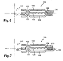
- the shim 130 of extra thickness may be disposed at the edges of the seal, at the periphery of the spacer block 120, as illustrated by the Figures 6 and 7 .
- edges of the recess 128 formed in the intermediate plate 120 may not be sufficient to immobilize the shim 130 of extra thickness.
- the shim 130 may be fixed to the intermediate plate 120 by any appropriate means, in particular by welding, as illustrated in FIG. figure 6 .
- the shim 130 may be attached to one of the active plates by any appropriate means, including welding.
- the shim 130 may simply be immobilized at least one of the outer plates 118 comprising a folded edge 132, as illustrated by FIG. figure 7 .
- the shim allowance may have a hole allowing the passage of a screw.
Landscapes
- Engineering & Computer Science (AREA)
- General Engineering & Computer Science (AREA)
- Mechanical Engineering (AREA)
- Gasket Seals (AREA)
- Tires In General (AREA)
- Fluid-Damping Devices (AREA)
Claims (10)
- Zylinderkopfdichtung mit zumindest einer Öffnung (112), die mit einer Verbrennungskammer korrespondiert, wobei die Dichtung einen Stapel von zumindest einem so genannten aktiven Blech (118) mit zumindest einer Rippe (122), welche die Öffnung oder Öffnungen umgebend angeordnet ist, und von zumindest einem Zwischenblech (120) sowie einer Beilage (124), Stopper genannt, enthält, die am Umfang der zumindest einen Öffnung (112) angeordnet und deren Dicke größer als das Zwichenblech (120) ist, wobei die Dichtung zumindest eine Beilage (130) mit so genannter Überdicke enthält, die in der Ebene des Zwischenblechs (120), dem oder den aktiven Blech(en) benachbart, außerhalb der Rippe oder Rippen (122) angeordnet ist, wobei die Beilage (130) mit Überdicke eine derartige Dicke aufweist, dass die Beilage (130) eine bezüglich dem Zwischenblech (120) lokalisierte Überdicke bildet, dadurch gekennzeichnet, dass das Zwischenblech (120) zumindest eine Ausnehmung oder einen Sitz (128) aufweist für die Aufnahme zumindest einer Beilage (130) mit Überdicke.
- Zylinderkopfdichtung nach Anspruch 1, dadurch gekennzeichnet, dass die Formen der Beilage (130) mit Überdicke mit denen der sie aufnehmenden Ausnehmung (128) zusammenwirken.
- Zylinderkopfdichtung nach Anspruch 1 oder 2, dadurch gekennzeichnet, dass die Ausnehmung (128) ein Durchbruch ist.
- Zylinderkopfdichtung nach einem der Ansprüche 1 bis 3, dadurch gekennzeichnet, dass die Beilage (130) mit Überdicke am Umfang des Zwischenblechs (120) angeordnet ist.
- Zylinderkopfdichtung nach Anspruch 4, dadurch gekennzeichnet, dass zumindest ein äußeres Blech (118) einen umgebogenen Rand (132) aufweist, um die Beilage (130) mit Überdicke festzulegen.
- Verfahren zur Herstellung einer Überdicke in einem Zwischenblech, das in eine Zylinderkopfdichtung eingebaut ist, wobei die Dichtung einen Stapel von zumindest einem so genannten aktiven Blech (118) mit zumindest einer Rippe (122), die zumindest eine Öffnung (112), die mit einer Verbrennungskammer korrespondiert, umgebend angeordnet ist, und von mindestens dem Zwischenblech (120) sowie eine Beilage (124), Stopper genannt, enthält, die am Umfang der zumindest einen Öffnung (112) angeordnet und deren Dicke größer als das Zwischenblech (120) ist, dadurch gekennzeichnet, dass es darin besteht, zumindest einen Sitz oder eine Ausnehmung (128) in dem Bereich zu realisieren, der außerhalb der Rippe oder Rippen (122) angeordnet ist, und in der Ausnehmung (128) eine Beilage (130) mit einer derartigen Dicke anzuordnen, dass die Beilage (130) eine bezüglich dem Zwischenblech (120) lokalisierte Überdicke bildet, welche es erlaubt, die mechanischen Beanspruchungen im Bereich des aktiven Blechs (118), die sich durch das Vorhandensein eines Stoppers (124) ergeben, zu reduzieren.
- Verfahren nach Anspruch 6, dadurch gekennzeichnet, dass zumindest eine durchgehende Ausnehmung (128) realisiert wird.
- Verfahren nach Anspruch 6 oder 7, dadurch gekennzeichnet, dass die mindestens eine Ausnehmung (128) durch Stanzen erhalten wird.
- Verfahren nach einem der Ansprüche 6 bis 8, dadurch gekennzeichnet, dass zumindest eine Ausnehmung (128) am Umfang des Zwischenblechs (120) realisiert wird.
- Verfahren nach Anspruch 9, dadurch gekennzeichnet, dass eine Umbiegung (132) im Bereich des umlaufenden Randes zumindest eines äußeren Blechs (118) realisiert wird, um eine Beilage (130) mit Überdicke, die am Umfang des Zwischenblechs (120) angeordnet ist, festzulegen.
Applications Claiming Priority (2)
| Application Number | Priority Date | Filing Date | Title |
|---|---|---|---|
| FR0350634A FR2860553B1 (fr) | 2003-10-02 | 2003-10-02 | Joint de culasse multicouche comprenant au moins une cale de surepaisseur |
| FR0350634 | 2003-10-02 |
Publications (2)
| Publication Number | Publication Date |
|---|---|
| EP1521019A1 EP1521019A1 (de) | 2005-04-06 |
| EP1521019B1 true EP1521019B1 (de) | 2011-07-06 |
Family
ID=34307556
Family Applications (1)
| Application Number | Title | Priority Date | Filing Date |
|---|---|---|---|
| EP04019799A Expired - Lifetime EP1521019B1 (de) | 2003-10-02 | 2004-08-20 | Mehrlagendichtung mit mindestens einem Stutzelement |
Country Status (8)
| Country | Link |
|---|---|
| US (1) | US20050140096A1 (de) |
| EP (1) | EP1521019B1 (de) |
| JP (1) | JP4313748B2 (de) |
| AT (1) | ATE515652T1 (de) |
| BR (1) | BRPI0404199A (de) |
| CA (1) | CA2480594A1 (de) |
| FR (1) | FR2860553B1 (de) |
| MX (1) | MXPA04009548A (de) |
Families Citing this family (12)
| Publication number | Priority date | Publication date | Assignee | Title |
|---|---|---|---|---|
| DE102004031611B4 (de) * | 2004-06-30 | 2013-03-28 | Federal-Mogul Sealing Systems Gmbh | Flachdichtung |
| US8496253B2 (en) * | 2007-04-24 | 2013-07-30 | Reinz-Dichtungs-Gmbh | Metallic flat gasket |
| US8632077B2 (en) | 2008-02-13 | 2014-01-21 | Federal-Mogul Corporation | Multilayer static gasket with bead compression limiter |
| JP5344222B2 (ja) * | 2008-12-26 | 2013-11-20 | 日本ガスケット株式会社 | シリンダヘッドガスケットにおけるオイル落し穴のシール構造 |
| CN102549317B (zh) * | 2009-06-24 | 2014-11-05 | 费德罗-莫格尔公司 | 汽缸盖垫片 |
| CN102549318B (zh) * | 2009-08-11 | 2014-09-24 | 费德罗-莫格尔公司 | 双金属静态垫圈及其构造方法 |
| WO2011103373A1 (en) * | 2010-02-19 | 2011-08-25 | Federal-Mogul Corporation | Multilayer gasket with labyrinth stopper |
| US9133698B2 (en) | 2010-12-21 | 2015-09-15 | Federal-Mogul Corporation | Modular fracture plug and method of construction thereof |
| US9695936B2 (en) * | 2011-04-14 | 2017-07-04 | Federal-Mogul Llc | Multilayer metal gasket with bead on stopper |
| BR112015030820A2 (pt) * | 2013-06-10 | 2017-07-25 | Federal Mogul Corp | junta de vedação estática e processo de construção da mesma |
| US20150226153A1 (en) * | 2014-02-13 | 2015-08-13 | Federal Mogul Corporation | Cylinder head gasket for high load and motion applications |
| US9664284B2 (en) * | 2015-08-05 | 2017-05-30 | General Electric Company | Cover system with gasket system therefor |
Family Cites Families (13)
| Publication number | Priority date | Publication date | Assignee | Title |
|---|---|---|---|---|
| US4519619A (en) * | 1984-09-25 | 1985-05-28 | Felt Products Mfg. Co. | High temperature resistant gasket having improved recovery characteristics |
| US4756561A (en) * | 1985-02-14 | 1988-07-12 | Mazda Motor Corporation | Sealing gasket |
| JPS62155375A (ja) * | 1985-12-27 | 1987-07-10 | Nippon Metal Gasket Kk | 金属ガスケツト |
| JPH0627877Y2 (ja) * | 1986-09-16 | 1994-07-27 | 石川ガスケット株式会社 | 金属積層形ガスケット |
| US5618049A (en) * | 1993-06-04 | 1997-04-08 | Japan Metal Gasket Co., Ltd. | Metallic gasket |
| DE19611092C2 (de) * | 1996-03-21 | 2001-04-26 | Elringklinger Gmbh | Verfahren zum Aufbringen einer Überhöhung auf eine Metallage einer Zylinderkopfdichtung und Zylinderkopfdichtung |
| US5979906A (en) * | 1997-02-13 | 1999-11-09 | Farnam/Meillor Sealing Systems Inc. | Multi-layered metal gasket assembly and method of constructing the same |
| US5979907A (en) * | 1997-12-30 | 1999-11-09 | Ishikawa Gasket Co., Ltd. | Metal gasket with edge support shim |
| JP3751786B2 (ja) * | 1999-12-27 | 2006-03-01 | 石川ガスケット株式会社 | 金属積層形ガスケット |
| JP2001280502A (ja) * | 2000-03-29 | 2001-10-10 | Nippon Gasket Co Ltd | 単層金属製ガスケット |
| DE20019412U1 (de) * | 2000-11-15 | 2001-01-11 | REINZ Dichtungs GmbH u. Co. KG, 89233 Neu-Ulm | Zylinderkopfdichtung |
| US6499743B2 (en) * | 2001-04-02 | 2002-12-31 | Federal-Mogul World Wide, Inc. | Gasket with dynamic joint motion control |
| EP1298365B1 (de) * | 2001-09-29 | 2009-09-02 | ElringKlinger AG | Metallische Zylinderkopfdichtung |
-
2003
- 2003-10-02 FR FR0350634A patent/FR2860553B1/fr not_active Expired - Fee Related
-
2004
- 2004-08-20 AT AT04019799T patent/ATE515652T1/de not_active IP Right Cessation
- 2004-08-20 EP EP04019799A patent/EP1521019B1/de not_active Expired - Lifetime
- 2004-09-23 CA CA002480594A patent/CA2480594A1/fr not_active Abandoned
- 2004-09-24 US US10/949,728 patent/US20050140096A1/en not_active Abandoned
- 2004-09-30 MX MXPA04009548A patent/MXPA04009548A/es unknown
- 2004-10-01 BR BR0404199-2A patent/BRPI0404199A/pt not_active IP Right Cessation
- 2004-10-04 JP JP2004290882A patent/JP4313748B2/ja not_active Expired - Fee Related
Also Published As
| Publication number | Publication date |
|---|---|
| FR2860553A1 (fr) | 2005-04-08 |
| CA2480594A1 (fr) | 2005-04-02 |
| ATE515652T1 (de) | 2011-07-15 |
| JP4313748B2 (ja) | 2009-08-12 |
| JP2005114166A (ja) | 2005-04-28 |
| MXPA04009548A (es) | 2005-07-05 |
| EP1521019A1 (de) | 2005-04-06 |
| FR2860553B1 (fr) | 2006-02-24 |
| BRPI0404199A (pt) | 2005-05-24 |
| US20050140096A1 (en) | 2005-06-30 |
Similar Documents
| Publication | Publication Date | Title |
|---|---|---|
| EP1521019B1 (de) | Mehrlagendichtung mit mindestens einem Stutzelement | |
| EP2142834B1 (de) | Vorrichtung für eine vorgespannte versiegelungsverbindung mit flanschen | |
| EP1637780B9 (de) | Dichtung mit mindestens einem Wulst mit integriertem Begrenzer | |
| FR2766252A1 (fr) | Bague d'etancheite metallique | |
| EP0028576B2 (de) | Zylinderkopfdichtung für Brennkraftmaschine | |
| EP2097705B1 (de) | Plattenwärmetauscher | |
| EP1430241B1 (de) | Zylinderkopfdichtung mit einem durch heften verbundenen, sich von rand zu rand erstreckenden anschlagring | |
| EP1693606B1 (de) | Metallische Dichtung mit einer Verdickung in Form von unterbrochenen Vorsprüngen | |
| EP1536166B1 (de) | Dichtung mit einem verdickten Blech | |
| FR2890096A1 (fr) | Porte isolante | |
| EP1409898B1 (de) | Zylinderkopfdichtung mit einem kante-zu-kante-anschlagsring | |
| EP1409897B1 (de) | Zylinderkopfdichtung mit einem rand-zu-rand-anschlagsring | |
| EP1536165A1 (de) | Passender Anschlagring und damit ausgestattete Zylinderkopfdichtung | |
| EP1555466B1 (de) | Verfahren zum Verdicken eines Blechs, sowie aus einem solchen Blech bestehende Flachdichtung | |
| FR2669703A1 (fr) | Joint d'etancheite statique. | |
| EP1541254B1 (de) | Verfahren zum Herstellen eines Bleches mit vergrösserter Wanddicke sowie Dichtung aus einem solchen Blech | |
| EP0524048B1 (de) | Dichtung mit metallischem Kern und expandierte Graphitdichtung | |
| EP2309527B1 (de) | Vorrichtung zur fügen durch schweißen eines Deckels am ende einer Zylinderkörper und Vakuumröhre mit einer solchen Vorrichtung | |
| EP1693605B1 (de) | Metallische Dichtung mit einer Verdickung in Form eines mäanderförmigen Vorsprungs | |
| FR2940363A1 (fr) | Joint de bloc moteur, notamment pour le montage d'un composant faiblement rigide sur ledit bloc moteur | |
| FR2827639A1 (fr) | Joint de culasse comprenant un stoppeur bord a bord | |
| FR2827637A1 (fr) | Joint de culasse comprenant un stoppeur bord a bord | |
| FR3118898A1 (fr) | Moule à injection à serrage concentré et machine de moulage par injection associée | |
| EP1248923A1 (de) | Dichtung und verfahren zur herstellung eines begrenzungsbleches auf dieser dichtung, insbesondere auf einer zylinderkopfsdichtung |
Legal Events
| Date | Code | Title | Description |
|---|---|---|---|
| PUAI | Public reference made under article 153(3) epc to a published international application that has entered the european phase |
Free format text: ORIGINAL CODE: 0009012 |
|
| 17P | Request for examination filed |
Effective date: 20050127 |
|
| AK | Designated contracting states |
Kind code of ref document: A1 Designated state(s): AT BE BG CH CY CZ DE DK EE ES FI FR GB GR HU IE IT LI LU MC NL PL PT RO SE SI SK TR |
|
| AX | Request for extension of the european patent |
Extension state: AL HR LT LV MK |
|
| AKX | Designation fees paid |
Designated state(s): AT BE BG CH CY CZ DE DK EE ES FI FR GB GR HU IE IT LI LU MC NL PL PT RO SE SI SK TR |
|
| 17Q | First examination report despatched |
Effective date: 20060717 |
|
| GRAP | Despatch of communication of intention to grant a patent |
Free format text: ORIGINAL CODE: EPIDOSNIGR1 |
|
| GRAS | Grant fee paid |
Free format text: ORIGINAL CODE: EPIDOSNIGR3 |
|
| GRAA | (expected) grant |
Free format text: ORIGINAL CODE: 0009210 |
|
| RAP1 | Party data changed (applicant data changed or rights of an application transferred) |
Owner name: ELRINGKLINGER AG |
|
| AK | Designated contracting states |
Kind code of ref document: B1 Designated state(s): AT BE BG CH CY CZ DE DK EE ES FI FR GB GR HU IE IT LI LU MC NL PL PT RO SE SI SK TR |
|
| REG | Reference to a national code |
Ref country code: GB Ref legal event code: FG4D Free format text: NOT ENGLISH |
|
| REG | Reference to a national code |
Ref country code: CH Ref legal event code: EP |
|
| REG | Reference to a national code |
Ref country code: IE Ref legal event code: FG4D Free format text: LANGUAGE OF EP DOCUMENT: FRENCH |
|
| REG | Reference to a national code |
Ref country code: DE Ref legal event code: R096 Ref document number: 602004033341 Country of ref document: DE Effective date: 20110901 |
|
| REG | Reference to a national code |
Ref country code: NL Ref legal event code: VDEP Effective date: 20110706 |
|
| PG25 | Lapsed in a contracting state [announced via postgrant information from national office to epo] |
Ref country code: SI Free format text: LAPSE BECAUSE OF FAILURE TO SUBMIT A TRANSLATION OF THE DESCRIPTION OR TO PAY THE FEE WITHIN THE PRESCRIBED TIME-LIMIT Effective date: 20110706 |
|
| REG | Reference to a national code |
Ref country code: AT Ref legal event code: MK05 Ref document number: 515652 Country of ref document: AT Kind code of ref document: T Effective date: 20110706 |
|
| PG25 | Lapsed in a contracting state [announced via postgrant information from national office to epo] |
Ref country code: NL Free format text: LAPSE BECAUSE OF FAILURE TO SUBMIT A TRANSLATION OF THE DESCRIPTION OR TO PAY THE FEE WITHIN THE PRESCRIBED TIME-LIMIT Effective date: 20110706 Ref country code: SE Free format text: LAPSE BECAUSE OF FAILURE TO SUBMIT A TRANSLATION OF THE DESCRIPTION OR TO PAY THE FEE WITHIN THE PRESCRIBED TIME-LIMIT Effective date: 20110706 Ref country code: FI Free format text: LAPSE BECAUSE OF FAILURE TO SUBMIT A TRANSLATION OF THE DESCRIPTION OR TO PAY THE FEE WITHIN THE PRESCRIBED TIME-LIMIT Effective date: 20110706 Ref country code: PT Free format text: LAPSE BECAUSE OF FAILURE TO SUBMIT A TRANSLATION OF THE DESCRIPTION OR TO PAY THE FEE WITHIN THE PRESCRIBED TIME-LIMIT Effective date: 20111107 |
|
| REG | Reference to a national code |
Ref country code: IE Ref legal event code: FD4D |
|
| BERE | Be: lapsed |
Owner name: ELRINGKLINGER A.G. Effective date: 20110831 |
|
| PG25 | Lapsed in a contracting state [announced via postgrant information from national office to epo] |
Ref country code: GR Free format text: LAPSE BECAUSE OF FAILURE TO SUBMIT A TRANSLATION OF THE DESCRIPTION OR TO PAY THE FEE WITHIN THE PRESCRIBED TIME-LIMIT Effective date: 20111007 Ref country code: CY Free format text: LAPSE BECAUSE OF FAILURE TO SUBMIT A TRANSLATION OF THE DESCRIPTION OR TO PAY THE FEE WITHIN THE PRESCRIBED TIME-LIMIT Effective date: 20110706 Ref country code: PL Free format text: LAPSE BECAUSE OF FAILURE TO SUBMIT A TRANSLATION OF THE DESCRIPTION OR TO PAY THE FEE WITHIN THE PRESCRIBED TIME-LIMIT Effective date: 20110706 Ref country code: AT Free format text: LAPSE BECAUSE OF FAILURE TO SUBMIT A TRANSLATION OF THE DESCRIPTION OR TO PAY THE FEE WITHIN THE PRESCRIBED TIME-LIMIT Effective date: 20110706 |
|
| PG25 | Lapsed in a contracting state [announced via postgrant information from national office to epo] |
Ref country code: MC Free format text: LAPSE BECAUSE OF NON-PAYMENT OF DUE FEES Effective date: 20110831 |
|
| REG | Reference to a national code |
Ref country code: CH Ref legal event code: PL |
|
| PG25 | Lapsed in a contracting state [announced via postgrant information from national office to epo] |
Ref country code: LI Free format text: LAPSE BECAUSE OF NON-PAYMENT OF DUE FEES Effective date: 20110831 Ref country code: CH Free format text: LAPSE BECAUSE OF NON-PAYMENT OF DUE FEES Effective date: 20110831 Ref country code: CZ Free format text: LAPSE BECAUSE OF FAILURE TO SUBMIT A TRANSLATION OF THE DESCRIPTION OR TO PAY THE FEE WITHIN THE PRESCRIBED TIME-LIMIT Effective date: 20110706 Ref country code: IE Free format text: LAPSE BECAUSE OF FAILURE TO SUBMIT A TRANSLATION OF THE DESCRIPTION OR TO PAY THE FEE WITHIN THE PRESCRIBED TIME-LIMIT Effective date: 20110706 Ref country code: SK Free format text: LAPSE BECAUSE OF FAILURE TO SUBMIT A TRANSLATION OF THE DESCRIPTION OR TO PAY THE FEE WITHIN THE PRESCRIBED TIME-LIMIT Effective date: 20110706 |
|
| PLBE | No opposition filed within time limit |
Free format text: ORIGINAL CODE: 0009261 |
|
| STAA | Information on the status of an ep patent application or granted ep patent |
Free format text: STATUS: NO OPPOSITION FILED WITHIN TIME LIMIT |
|
| PG25 | Lapsed in a contracting state [announced via postgrant information from national office to epo] |
Ref country code: RO Free format text: LAPSE BECAUSE OF FAILURE TO SUBMIT A TRANSLATION OF THE DESCRIPTION OR TO PAY THE FEE WITHIN THE PRESCRIBED TIME-LIMIT Effective date: 20110706 Ref country code: BE Free format text: LAPSE BECAUSE OF NON-PAYMENT OF DUE FEES Effective date: 20110831 Ref country code: EE Free format text: LAPSE BECAUSE OF FAILURE TO SUBMIT A TRANSLATION OF THE DESCRIPTION OR TO PAY THE FEE WITHIN THE PRESCRIBED TIME-LIMIT Effective date: 20110706 Ref country code: IT Free format text: LAPSE BECAUSE OF FAILURE TO SUBMIT A TRANSLATION OF THE DESCRIPTION OR TO PAY THE FEE WITHIN THE PRESCRIBED TIME-LIMIT Effective date: 20110706 |
|
| 26N | No opposition filed |
Effective date: 20120411 |
|
| GBPC | Gb: european patent ceased through non-payment of renewal fee |
Effective date: 20111006 |
|
| PG25 | Lapsed in a contracting state [announced via postgrant information from national office to epo] |
Ref country code: DK Free format text: LAPSE BECAUSE OF FAILURE TO SUBMIT A TRANSLATION OF THE DESCRIPTION OR TO PAY THE FEE WITHIN THE PRESCRIBED TIME-LIMIT Effective date: 20110706 |
|
| REG | Reference to a national code |
Ref country code: DE Ref legal event code: R097 Ref document number: 602004033341 Country of ref document: DE Effective date: 20120411 |
|
| PG25 | Lapsed in a contracting state [announced via postgrant information from national office to epo] |
Ref country code: GB Free format text: LAPSE BECAUSE OF NON-PAYMENT OF DUE FEES Effective date: 20111006 |
|
| PG25 | Lapsed in a contracting state [announced via postgrant information from national office to epo] |
Ref country code: ES Free format text: LAPSE BECAUSE OF FAILURE TO SUBMIT A TRANSLATION OF THE DESCRIPTION OR TO PAY THE FEE WITHIN THE PRESCRIBED TIME-LIMIT Effective date: 20111017 |
|
| PG25 | Lapsed in a contracting state [announced via postgrant information from national office to epo] |
Ref country code: LU Free format text: LAPSE BECAUSE OF NON-PAYMENT OF DUE FEES Effective date: 20110820 |
|
| PG25 | Lapsed in a contracting state [announced via postgrant information from national office to epo] |
Ref country code: BG Free format text: LAPSE BECAUSE OF FAILURE TO SUBMIT A TRANSLATION OF THE DESCRIPTION OR TO PAY THE FEE WITHIN THE PRESCRIBED TIME-LIMIT Effective date: 20111006 |
|
| PG25 | Lapsed in a contracting state [announced via postgrant information from national office to epo] |
Ref country code: TR Free format text: LAPSE BECAUSE OF FAILURE TO SUBMIT A TRANSLATION OF THE DESCRIPTION OR TO PAY THE FEE WITHIN THE PRESCRIBED TIME-LIMIT Effective date: 20110706 |
|
| PG25 | Lapsed in a contracting state [announced via postgrant information from national office to epo] |
Ref country code: HU Free format text: LAPSE BECAUSE OF FAILURE TO SUBMIT A TRANSLATION OF THE DESCRIPTION OR TO PAY THE FEE WITHIN THE PRESCRIBED TIME-LIMIT Effective date: 20110706 |
|
| REG | Reference to a national code |
Ref country code: DE Ref legal event code: R082 Ref document number: 602004033341 Country of ref document: DE Representative=s name: HOEGER, STELLRECHT & PARTNER PATENTANWAELTE MB, DE |
|
| REG | Reference to a national code |
Ref country code: FR Ref legal event code: PLFP Year of fee payment: 13 |
|
| PGFP | Annual fee paid to national office [announced via postgrant information from national office to epo] |
Ref country code: FR Payment date: 20160825 Year of fee payment: 13 |
|
| REG | Reference to a national code |
Ref country code: FR Ref legal event code: ST Effective date: 20180430 |
|
| PG25 | Lapsed in a contracting state [announced via postgrant information from national office to epo] |
Ref country code: FR Free format text: LAPSE BECAUSE OF NON-PAYMENT OF DUE FEES Effective date: 20170831 |
|
| PGFP | Annual fee paid to national office [announced via postgrant information from national office to epo] |
Ref country code: DE Payment date: 20180827 Year of fee payment: 15 |
|
| REG | Reference to a national code |
Ref country code: DE Ref legal event code: R082 Ref document number: 602004033341 Country of ref document: DE Representative=s name: HOEGER, STELLRECHT & PARTNER PATENTANWAELTE MB, DE |
|
| REG | Reference to a national code |
Ref country code: DE Ref legal event code: R119 Ref document number: 602004033341 Country of ref document: DE |
|
| PG25 | Lapsed in a contracting state [announced via postgrant information from national office to epo] |
Ref country code: DE Free format text: LAPSE BECAUSE OF NON-PAYMENT OF DUE FEES Effective date: 20200303 |