EP1521019B1 - Multi-layered gasket with at least a thickening shim - Google Patents
Multi-layered gasket with at least a thickening shim Download PDFInfo
- Publication number
- EP1521019B1 EP1521019B1 EP04019799A EP04019799A EP1521019B1 EP 1521019 B1 EP1521019 B1 EP 1521019B1 EP 04019799 A EP04019799 A EP 04019799A EP 04019799 A EP04019799 A EP 04019799A EP 1521019 B1 EP1521019 B1 EP 1521019B1
- Authority
- EP
- European Patent Office
- Prior art keywords
- metal sheet
- shim
- inter
- layer metal
- thickness
- Prior art date
- Legal status (The legal status is an assumption and is not a legal conclusion. Google has not performed a legal analysis and makes no representation as to the accuracy of the status listed.)
- Not-in-force
Links
- 230000008719 thickening Effects 0.000 title description 2
- 238000000034 method Methods 0.000 claims abstract description 12
- 238000002485 combustion reaction Methods 0.000 claims abstract description 10
- 239000002184 metal Substances 0.000 claims description 23
- 238000004519 manufacturing process Methods 0.000 claims description 2
- 230000002093 peripheral effect Effects 0.000 claims description 2
- 239000011229 interlayer Substances 0.000 claims 14
- 239000011324 bead Substances 0.000 claims 6
- 125000006850 spacer group Chemical group 0.000 abstract description 6
- 230000015572 biosynthetic process Effects 0.000 abstract 1
- 230000002787 reinforcement Effects 0.000 abstract 1
- 239000011888 foil Substances 0.000 description 5
- 239000012809 cooling fluid Substances 0.000 description 3
- 238000005096 rolling process Methods 0.000 description 3
- 238000003466 welding Methods 0.000 description 3
- 239000000463 material Substances 0.000 description 2
- 238000004080 punching Methods 0.000 description 2
- 238000005520 cutting process Methods 0.000 description 1
- 230000007547 defect Effects 0.000 description 1
- 238000003754 machining Methods 0.000 description 1
- 239000011347 resin Substances 0.000 description 1
- 229920005989 resin Polymers 0.000 description 1
- 238000007650 screen-printing Methods 0.000 description 1
- 238000009827 uniform distribution Methods 0.000 description 1
Images


Classifications
-
- F—MECHANICAL ENGINEERING; LIGHTING; HEATING; WEAPONS; BLASTING
- F16—ENGINEERING ELEMENTS AND UNITS; GENERAL MEASURES FOR PRODUCING AND MAINTAINING EFFECTIVE FUNCTIONING OF MACHINES OR INSTALLATIONS; THERMAL INSULATION IN GENERAL
- F16J—PISTONS; CYLINDERS; SEALINGS
- F16J15/00—Sealings
- F16J15/02—Sealings between relatively-stationary surfaces
- F16J15/06—Sealings between relatively-stationary surfaces with solid packing compressed between sealing surfaces
- F16J15/08—Sealings between relatively-stationary surfaces with solid packing compressed between sealing surfaces with exclusively metal packing
- F16J15/0818—Flat gaskets
- F16J15/0825—Flat gaskets laminated
Definitions
- the present invention relates to a multilayer gasket comprising at least one thicker shim, and more particularly to a multilayer metal gasket.
- a cylinder head gasket is used to seal between an engine block and a cylinder head.
- a cylinder head gasket 10 generally has the shape of the engine block, in particular rectangular, and comprises a plurality of openings, making it possible to ensure continuity between cavities or ducts arranged on the one hand in the engine block, and other part in the breech.
- first openings 12 are provided for the combustion chambers
- second openings 14 for the ducts of the cooling fluid or fluids
- third openings 16 to allow the passage of bolt fixing elements on the engine block, in particular threaded rods.
- the cylinder head gasket must ensure a good seal between the ducts between them and between the ducts and the outside despite the geometric defects of the surfaces in contact with the engine block and the cylinder head and the temperature variations.
- a cylinder head gasket 10 comprises a plurality of stacked sheets or sheets, in particular two active outer plates 18 between which an intermediate sheet 20 is disposed. At least one of the outer plates 18 has a rib 22 around the first openings 12, close to said openings, facing towards the inside of the joint, in order to obtain a zone deformable to compensate for the deformations of the joint.
- ribs 22 are provided on the two outer plates 18, the projecting portions of said ribs are arranged opposite and oriented towards each other or in opposition.
- said gasket 10 comprises a wedge 24 called a stopper disposed at the periphery of the first openings 12 provided for the combustion chambers and edge to edge with the intermediate plate 20.
- This stopper 24 has a thickness slightly greater than the sheet metal insert 20 allowing on the one hand to obtain a higher clamping force around the combustion chambers, and on the other hand, to obtain a pre-stress of at least one of the outer plates 18 reducing the range of movement and the crushing of the ribs.
- the stopper may have a variable thickness to obtain a uniform distribution of the clamping force on the periphery of the openings 12 provided for the combustion chambers.
- the extra thickness is obtained by bringing on the surface of the intermediate sheet 20 a foil 26 or a thin sheet, less than or equal to 0.1 mm thick.
- the extra thickness is obtained by stamping the intermediate sheet 20 to provide a variable thickness.
- This solution is also not satisfactory because the stamping of a sheet to give localized variable thickness is relatively complex and expensive to implement. Moreover, this stamping technique does not make it possible to obtain thicknesses of precise dimensions, unlike the rolling technique.
- the extra thickness is obtained using a resin deposited by screen printing on the intermediate sheet. This solution is also relatively complex and expensive to implement.
- the present invention aims to overcome the drawbacks of the prior art by providing a multilayer gasket with a localized variable thickness thickness sheet metal of simple design whose implementation is easy and relatively less expensive.
- the subject of the invention is a cylinder head gasket with at least one orifice corresponding to a combustion chamber, said gasket comprising a stack of at least one so-called active sheet comprising at least one rib formed around said orifice or said orifice.
- the seal comprising at least one so-called shim allowance arranged in the plane of the intermediate sheet, at the right of the active sheet (s), outside the rib or ribs, said thickening wedge having a thickness such that said wedge is a localized allowance relative to the intermediate sheet, characterized in that the intermediate sheet comprises at least one recess or a housing capable of receiving at least one extra thickness wedge.
- the shim is arranged in a housing formed in the intermediate sheet, the forms of the spacer interminging with those housing that receives it. This arrangement allows a better immobilization of the shim extra thickness.
- the housing is opening.
- This variant has the advantage of simplifying the procedure and to obtain an accurate extra thickness corresponding to the thickness of the shim of extra thickness obtained by rolling.
- the invention also proposes a method for producing an extra thickness in a spacer plate of a cylinder head gasket.
- FIG. 1 On the figure 1 , there is shown a cylinder head gasket 100.
- This type of seal interposed between an engine block and a cylinder head comprises a plurality of openings for ensuring continuity between cavities or ducts in said engine block and said cylinder head. So, the seal of cylinder head 100 must seal between the cavities or ducts between them and with the outside.
- the cylinder head gasket 100 comprises first openings 112 provided for the combustion chambers, second openings 114 provided for conduits or cooling fluids and third openings 116 provided to allow the passage fasteners of the cylinder head on the engine block, including threaded rods.
- This cylinder head gasket 100 comprises a plurality of stacked sheets or sheets, in particular two active outer plates 118 between which an intermediate sheet 120 is disposed. At least one of the outer plates 118 has a rib 122 around the first openings 112, close to said openings. , oriented towards the inside of the seal, in order to obtain a deformable zone making it possible to compensate the deformations of the seal.
- ribs 122 are provided on the two outer plates 118, the projecting portions of said ribs are preferably arranged facing each other and oriented towards each other.
- the rib or ribs 122 define two zones, a first zone inside the rib or ribs and a second zone outside the rib or ribs 122 called non-gas zone.
- said seal 110 comprises a wedge 124 called a stopper, of greater thickness than the intermediate sheet 120, disposed at the periphery of the first openings 112 and edge to edge with the intermediate plate 120.
- the seal 110 comprises at least one shim 130 called extra thickness disposed in the plane of the intermediate sheet 120, to the right of the active sheet or plates 118, outside the rib or ribs, said shim excess thickness having a thickness such that said shim 130 is a localized allowance relative to the intermediate plate 120.
- a portion of the shim 130 is capable of coming into contact with at least a portion of the section of the intermediate plate 120, the corresponding section being at the edge. peripheral of the intermediate sheet, either at the edge of a housing or recess formed in the intermediate sheet.
- part of the shim 130 is able to come into contact with at least one active sheet or is placed between two active plates.
- the shim 130 of extra thickness is disposed in a housing or a recess 128 formed in the intermediate plate 120.
- the shapes of the shim 130 of extra thickness cooperate with those of the housing 128 which receives it in order to limit the relative movements in the plane of the intermediate plate 120.
- the shim 130 is immobilized in translation by the edges of the housing 128 and has a thickness greater than that of a foil 26 of the prior art facilitating its implementation.
- a material removal machining operation to provide a housing or recess is relatively simpler and less expensive to perform than a stamping operation.
- the housing 128 may be non-opening as illustrated on the figure 3 or emerging as shown on the figure 4 .
- This second variant has the advantage of simplifying the procedure and to obtain an accurate extra thickness corresponding to the thickness of the shim 130 of extra thickness obtained by rolling.
- the second variant is illustrated in perspective on the figure 5 .
- the extra thickness generated by the shim 130 makes it possible to reduce the mechanical stresses at the level of the outer plates 118 and to obtain a uniform clamping pressure over the entire surface of the joint.
- the housings 128 made in the intermediate plate 120 are obtained by punching, preferably during the cutting of the openings 112, 114 and 116.
- the shims 130 of extra thickness can also be obtained by punching. They can have contours of different shapes.
- the shim 130 of extra thickness is simply immobilized in its housing 128 so that a fixation is no longer necessary.
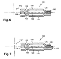
- the shim 130 of extra thickness may be disposed at the edges of the seal, at the periphery of the spacer block 120, as illustrated by the Figures 6 and 7 .
- edges of the recess 128 formed in the intermediate plate 120 may not be sufficient to immobilize the shim 130 of extra thickness.
- the shim 130 may be fixed to the intermediate plate 120 by any appropriate means, in particular by welding, as illustrated in FIG. figure 6 .
- the shim 130 may be attached to one of the active plates by any appropriate means, including welding.
- the shim 130 may simply be immobilized at least one of the outer plates 118 comprising a folded edge 132, as illustrated by FIG. figure 7 .
- the shim allowance may have a hole allowing the passage of a screw.
Abstract
Description
La présente invention se rapporte à un joint multicouche comprenant au moins une cale de surépaisseur, et plus particulièrement à un joint de culasse métallique multicouche.The present invention relates to a multilayer gasket comprising at least one thicker shim, and more particularly to a multilayer metal gasket.
Un joint de culasse est utilisé pour assurer l'étanchéité entre un bloc moteur et une culasse. Comme illustré sur la
Selon un mode de réalisation répandu et illustré par les
Pour améliorer l'étanchéité, ledit joint 10 comprend une cale 24 appelée stoppeur, disposée en périphérie des premières ouvertures 12 prévues pour les chambres de combustion et bord à bord avec la tôle intercalaire 20. Ce stoppeur 24 a une épaisseur légèrement supérieure à la tôle intercalaire 20 permettant d'une part d'obtenir un effort de serrage plus élevé autour des chambres de combustion, et d'autre part, d'obtenir une pré-contrainte d'au moins une des tôles extérieures 18 réduisant l'amplitude de débattement et l'écrasement des nervures.To improve the seal, said
En fonction de l'agencement des éléments de serrage, le stoppeur peut avoir une épaisseur variable pour obtenir une répartition homogène de l'effort de serrage sur la périphérie des ouvertures 12 prévues pour les chambres de combustion.Depending on the arrangement of the clamping elements, the stopper may have a variable thickness to obtain a uniform distribution of the clamping force on the periphery of the
La présence d'un stoppeur 24 dont l'épaisseur est toujours supérieure à la tôle intercalaire 20 provoque des contraintes mécaniques au niveau des tôles extérieures 18 en raison de l'arc-boutement desdites tôles extérieures au moment du serrage. D'autre part, il est nécessaire d'avoir une pression de serrage homogène sur l'ensemble de la surface du joint de culasse 10 pour obtenir une bonne étanchéité.The presence of a
Aussi, pour résoudre ces problèmes, des surépaisseurs localisées sont prévues au niveau de la tôle intercalaire, dans la zone dite hors gaz c'est-à-dire à l'extérieur des nervures 22, permettant de réduire les contraintes et d'obtenir une pression de serrage homogène sur l'ensemble de la surface du joint.Also, to solve these problems, localized extra thicknesses are provided at the intermediate sheet, in the so-called non-gas zone that is to say outside the
Selon un premier mode de réalisation connu et illustré par la
Cette solution n'est pas satisfaisante car la mise en place du clinquant n'est pas aisée, ce dernier étant susceptible de se plier. Par ailleurs, il est nécessaire que le clinquant soit lié mécaniquement à la tôle intercalaire pour jouer pleinement son rôle. Or, la fixation d'un élément extrêmement mince est relativement complexe et coûteuse.This solution is not satisfactory because the establishment of the foil is not easy, the latter being likely to bend. Furthermore, it is necessary that the foil is mechanically linked to the intermediate sheet to play its full role. However, the fixing of an extremely thin element is relatively complex and expensive.
Selon un second mode de réalisation connu et illustré par la
Aussi, la présente invention vise à pallier les inconvénients de l'art antérieur en proposant un joint multicouche avec une tôle intercalaire à épaisseur variable localisée de conception simple dont la mise en oeuvre est aisée et relativement moins coûteuse.Also, the present invention aims to overcome the drawbacks of the prior art by providing a multilayer gasket with a localized variable thickness thickness sheet metal of simple design whose implementation is easy and relatively less expensive.
A cet effet, l'invention a pour objet un joint de culasse avec au moins un orifice correspondant à une chambre de combustion, ledit joint comprenant un empilage d'au moins une tôle dite active comportant au moins une nervure ménagée autour dudit ou desdits orifice(s), et d'au moins une tôle intercalaire ainsi qu'une cale appelée stoppeur, disposée en périphérie dudit au moins un orifice dont l'épaisseur est supérieure à la tôle intercalaire, le joint comprenant au moins une cale dite de surépaisseur disposée dans le plan de la tôle intercalaire, au droit de la ou des tôle(s) active(s), à l'extérieur de la ou des nervures, ladite cale de surépaisseur ayant une épaisseur telle que ladite cale constitue une surépaisseur localisée par rapport à la tôle intercalaire, caractérisé en ce que la tôle intercalaire comprend au moins un évidement ou un logement susceptible de recevoir au moins une cale de surépaisseur. Ainsi, la cale de surépaisseur est disposée dans un logement ménagé dans la tôle intercalaire, les formes de la cale intercalaire coopérant avec celles du logement qui la reçoit. Cet agencement permet une meilleure immobilisation de la cale de surépaisseur.For this purpose, the subject of the invention is a cylinder head gasket with at least one orifice corresponding to a combustion chamber, said gasket comprising a stack of at least one so-called active sheet comprising at least one rib formed around said orifice or said orifice. (s), and at least one intermediate sheet and a shim called stopper, arranged at the periphery of said at least one orifice whose thickness is greater than the intermediate sheet, the seal comprising at least one so-called shim allowance arranged in the plane of the intermediate sheet, at the right of the active sheet (s), outside the rib or ribs, said thickening wedge having a thickness such that said wedge is a localized allowance relative to the intermediate sheet, characterized in that the intermediate sheet comprises at least one recess or a housing capable of receiving at least one extra thickness wedge. Thus, the shim is arranged in a housing formed in the intermediate sheet, the forms of the spacer interminging with those housing that receives it. This arrangement allows a better immobilization of the shim extra thickness.
De préférence, le logement est débouchant. Cette variante a pour avantage de simplifier le mode opératoire et d'obtenir une surépaisseur précise correspondant à l'épaisseur de la cale de surépaisseur obtenue par laminage.Preferably, the housing is opening. This variant has the advantage of simplifying the procedure and to obtain an accurate extra thickness corresponding to the thickness of the shim of extra thickness obtained by rolling.
L'invention propose également un procédé pour la réalisation d'une surépaisseur dans une tôle intercalaire d'un joint de culasse.The invention also proposes a method for producing an extra thickness in a spacer plate of a cylinder head gasket.
D'autres caractéristiques et avantages ressortiront de la description qui va suivre de l'invention, description donnée à titre d'exemple uniquement, en regard des dessins annexés sur lesquels:
- la
figure 1 est une vue en élévation de dessus d'un joint de culasse, - la
figure 2A est une coupe selon la ligne II-II de lafigure 1 d'un premier mode de réalisation selon l'art antérieur, - la
figure 2B est une coupe selon la ligne II-II de lafigure 1 d'un second mode de réalisation selon l'art antérieur, - la
figure 3 est une coupe selon la ligne II-II de lafigure 1 d'un premier mode de réalisation selon l'invention, - la
figure 4 est une coupe selon la ligne II-II de lafigure 1 d'un second mode de réalisation selon l'invention, - la
figure 5 est une vue en perspective et en coupe du joint de lafigure 4 , - la
figure 6 est une vue en coupe illustrant un mode de réalisation d'un joint avec une cale de surépaisseur disposée en périphérie du joint, et - la
figure 7 est une vue en coupe illustrant une autre variante d'un mode de fixation d'une cale de surépaisseur disposée en périphérie du joint.
- the
figure 1 is a top view of a cylinder head gasket, - the
Figure 2A is a section along line II-II of thefigure 1 of a first embodiment according to the prior art, - the
Figure 2B is a section along line II-II of thefigure 1 of a second embodiment according to the prior art, - the
figure 3 is a section along line II-II of thefigure 1 of a first embodiment according to the invention, - the
figure 4 is a section along line II-II of thefigure 1 of a second embodiment according to the invention, - the
figure 5 is a perspective view in section of the seal of thefigure 4 , - the
figure 6 is a sectional view illustrating an embodiment of a seal with a shim extra thickness disposed at the periphery of the seal, and - the
figure 7 is a sectional view illustrating another variant of a method of fixing a shim extra thickness disposed at the periphery of the seal.
Sur la
Ce type de joint interposé entre un bloc moteur et une culasse comprend une pluralité d'ouvertures permettant d'assurer la continuité entre des cavités ou des conduits ménagés dans ledit bloc moteur et ladite culasse. Ainsi, le joint de culasse 100 doit assurer l'étanchéité entre les cavités ou conduits entre eux et avec l'extérieur.This type of seal interposed between an engine block and a cylinder head comprises a plurality of openings for ensuring continuity between cavities or ducts in said engine block and said cylinder head. So, the seal of
Pour la suite de la description, les éléments communs avec les variantes de l'art antérieur portent les mêmes références augmentées de 100.For the rest of the description, the elements common with the variants of the prior art bear the same references increased by 100.
Ainsi, comme illustré sur les différentes figures, le joint de culasse 100 comprend des premières ouvertures 112 prévues pour les chambres à combustion, des deuxièmes ouvertures 114 prévues pour des conduits du ou des fluides de refroidissement et des troisièmes ouvertures 116 prévues pour permettre le passage d'éléments de fixation de la culasse sur le bloc moteur, notamment des tiges filetées.Thus, as illustrated in the various figures, the
Ce joint de culasse 100 comprend plusieurs feuilles ou tôles empilées, notamment deux tôles extérieures 118 actives entre lesquelles est disposée une tôle intercalaire 120. Au moins l'une des tôles extérieures 118 comporte une nervure 122 autour des premières ouvertures 112, à proximité desdites ouvertures, orientée vers l'intérieur du joint, afin d'obtenir une zone déformable permettant de compenser les déformations du joint. Ainsi, lorsque des nervures 122 sont prévues sur les deux tôles extérieures 118, les parties en saillie desdites nervures sont de préférence disposées en vis à vis et orientées l'une vers l'autre. Ainsi, la ou les nervures 122 délimitent deux zones, une première zone à l'intérieur de la ou des nervures et une seconde zone à l'extérieur de la ou des nervures 122 appelée zone hors gaz.This
Pour améliorer l'étanchéité, ledit joint 110 comprend une cale 124 appelée stoppeur, d'épaisseur supérieure à la tôle intercalaire 120, disposée en périphérie des premières ouvertures 112 et bord à bord avec la tôle intercalaire 120.To improve the seal, said seal 110 comprises a
Selon l'invention, le joint 110 comprend au moins une cale 130 dite de surépaisseur disposée dans le plan de la tôle intercalaire 120, au droit de la ou des tôles actives 118, à l'extérieur de la ou des nervures, ladite cale de surépaisseur ayant une épaisseur telle que ladite cale 130 constitue une surépaisseur localisée par rapport à la tôle intercalaire 120.According to the invention, the seal 110 comprises at least one
Par être disposée dans le plan de la tôle intercalaire 120, on entend qu'une partie de la cale de surépaisseur 130 est susceptible de venir en contact contre au moins une partie de la section de la tôle intercalaire 120, la section correspondant soit au bord périphérique de la tôle intercalaire, soit au bord d'un logement ou évidement ménagé dans la tôle intercalaire.By being disposed in the plane of the
Par être disposée au droit de la ou des tôles actives 118, on entend qu'une partie de la cale de surépaisseur 130 est susceptible de venir en contact contre au moins une tôle active ou est disposée entre deux tôles actives.By being arranged in line with the active sheet (s) 118, it is meant that part of the
La cale 130 de surépaisseur est disposée dans un logement ou un évidemment 128 ménagé dans la tôle intercalaire 120.The
Avantageusement, les formes de la cale 130 de surépaisseur coopèrent avec celles du logement 128 qui la reçoit afin de limiter les mouvements relatifs dans le plan de la tôle intercalaire 120.Advantageously, the shapes of the
La cale de surépaisseur 130 est immobilisée en translation par les bords du logement 128 et a une épaisseur supérieure à celle d'un clinquant 26 de l'art antérieur facilitant sa mise en oeuvre. De manière générale, une opération d'usinage d'enlèvement de matière afin de réaliser un logement ou un évidement est relativement plus simple et moins coûteuse à réaliser qu'une opération de matriçage.The
Selon les cas, le logement 128 peut être non débouchant tel qu'illustré sur la
La seconde variante est illustrée en perspective sur la
Conformément à l'art antérieur, la surépaisseur générée par la cale 130 permet de réduire les contraintes mécaniques au niveau des tôles extérieures 118 et d'obtenir une pression de serrage homogène sur l'ensemble de la surface du joint.According to the prior art, the extra thickness generated by the
Selon un mode de réalisation préféré, les logements 128 réalisés dans la tôle intercalaire 120 sont obtenus par poinçonnage, de préférence lors des découpes des ouvertures 112, 114 et 116. En complément, les cales 130 de surépaisseur peuvent être également obtenues par poinçonnage. Elles peuvent avoir des contours de différentes formes.According to a preferred embodiment, the
Contrairement à un clinquant qui doit être fixé à la tôle intercalaire par tout moyen approprié pour ne pas bouger, la cale 130 de surépaisseur est simplement immobilisée dans son logement 128 si bien qu'une fixation n'est plus nécessaire.Unlike a foil that must be fixed to the intermediate sheet by any appropriate means to stay in motion, the
En variante, la cale 130 de surépaisseur peut être disposée au niveau des bords du joint, en périphérie de la cale intercalaire 120, comme illustré par les
Dans ce cas, les bords de l'évidement 128 ménagé dans la tôle intercalaire 120 peuvent ne pas suffire pour immobiliser la cale 130 de surépaisseur.In this case, the edges of the
Selon une première variante, la cale 130 peut être fixée à la tôle intercalaire 120 par tout moyen approprié, notamment par soudage, comme illustré sur la
Selon une autre variante, la cale de surépaisseur 130 peut être fixée à une des tôles actives par tout moyen approprié, notamment par soudage.According to another variant, the
Selon une autre variante, la cale 130 peut être simplement immobilisée au moins l'une des tôles extérieures 118 comprenant un bord 132 replié, comme illustré par la
Les résultats les plus probants sont obtenus lorsque la cale de surépaisseur 130 est disposée en périphérie de la tôle intercalaire 120.The most convincing results are obtained when the
Ces résultats sont encore améliorés en combinant une cale de surépaisseur disposée en périphérie de la tôle intercalaire à des cales de surépaisseur disposées autour des passages de vis 116. Ainsi, selon l'invention, la cale de surépaisseur peut présenter un trou permettant le passage d'un vis. Cette solution a pour avantage d'obtenir l'immobilisation de la cale de surépaisseur entre les tôles actives et de ne pas lier de manière mécanique, par exemple par soudage, ladite cale de surépaisseur avec l'une des tôles actives ou la tôle intercalaire.These results are further improved by combining a wedge of extra thickness disposed at the periphery of the intermediate sheet to shims of extra thickness disposed around the
Bien entendu, l'invention n'est évidemment pas limitée au mode de réalisation représenté et décrit ci-dessus, mais couvre toutes les variantes, notamment en ce qui concerne les formes, les dimensions et les matériaux des différents éléments constituant le joint, selon les revendications.Of course, the invention is obviously not limited to the embodiment shown and described above, but covers all variants, in particular as regards the shapes, dimensions and materials of the various elements constituting the joint, according to the revendications.
Enfin, en variante, on pourrait envisager un stoppeur et une cale intercalaire d'un seul tenant, le stoppeur étant obtenu grâce à une surépaisseur au niveau de l'ouverture prévue pour les chambres de combustion, notamment par un pliage de la tôle intercalaire.Finally, alternatively, one could consider a stopper and a wedge insert in one piece, the stopper being obtained through an extra thickness at the opening provided for the combustion chambers, including a folding of the intermediate sheet.
Claims (10)
- Cylinder head gasket comprising at least one opening (112) corresponding to a combustion chamber, said gasket comprising a pile of at least one active metal sheet (118) being provided with at least one bead (122) arranged around said opening or openings, at least one inter-layer metal sheet (120), and a shim (124) called a stopper, arranged at the periphery of said at least one opening (112) and thicker than the inter-layer metal sheet (120), said gasket comprising at least one extra thickness shim (130) arranged in the plane of the inter-layer metal sheet (120), in front of the active metal sheet or sheets, and on the outside of the bead or beads (122), said extra thickness shim (130) having such a thickness that said shim (130) forms a localized increase in thickness in comparison to the inter-layer metal sheet (120), characterized in that the inter-layer metal sheet (120) comprises at least one recess or nest (128) capable of receiving at least one extra thickness shim (130).
- Cylinder head gasket as claimed in claim 1, characterized in that the shapes of the extra thickness shim (130) correspond to the shapes of the recess (128) which receives said extra thickness shim (130).
- Cylinder head gasket as claimed in claim 1 or 2, characterized in that the recess (128) goes all the way through the inter-layer metal sheet (120).
- Cylinder head gasket as claimed in any of claims 1 to 3, characterized in that the extra thickness shim (130) is arranged at the periphery of the inter-layer metal sheet (120).
- Cylinder head gasket as claimed in claim 4, characterized in that at least one outside metal sheet (118) comprises a bent edge (132) in order to immobilize the extra thickness shim (130).
- Method of making an increase in thickness in an inter-layer metal sheet integrated in a cylinder head gasket, said gasket comprising a pile of at least one active metal sheet (118) being provided with at least one bead (122) arranged around at least one opening (112) corresponding to a combustion chamber, at least the inter-layer metal sheet (120), and a shim (124) called a stopper, arranged at the periphery of said at least one opening (112) and thicker than the inter-layer metal sheet (120), characterized in that said method consists in providing at least one recess or nest (128) in the zone situated on the outside of the bead or beads (122), and in placing in said recess (128) a shim (130) having such a thickness that said shim (130) forms a localized increase in thickness in comparison to the inter-layer metal sheet (120) allowing a reduction of the mechanical stresses in the active metal sheet (118) resulting from the presence of a stopper (124).
- Method as claimed in claim 6, characterized in that at least one recess (128) going all the way through the inter-layer metal sheet (120) is provided.
- Method as claimed in claim 6 or 7, characterized in that said, at least one, recess (128) is obtained via a stamping process.
- Method as claimed in any of claims 6 to 8, characterized in that at least one recess (128) is provided at the periphery of the inter-layer metal sheet (120).
- Method as claimed in claim 9, characterized in that a bend (132) is provided in the peripheral edge of at least one outside metal sheet (118) in order to immobilize an extra thickness shim (130) arranged at the periphery of the inter-layer metal sheet (120).
Applications Claiming Priority (2)
| Application Number | Priority Date | Filing Date | Title |
|---|---|---|---|
| FR0350634 | 2003-10-02 | ||
| FR0350634A FR2860553B1 (en) | 2003-10-02 | 2003-10-02 | MULTILAYER CYLINDER HEAD COMPRISING AT LEAST ONE FREEZER HOLDER |
Publications (2)
| Publication Number | Publication Date |
|---|---|
| EP1521019A1 EP1521019A1 (en) | 2005-04-06 |
| EP1521019B1 true EP1521019B1 (en) | 2011-07-06 |
Family
ID=34307556
Family Applications (1)
| Application Number | Title | Priority Date | Filing Date |
|---|---|---|---|
| EP04019799A Not-in-force EP1521019B1 (en) | 2003-10-02 | 2004-08-20 | Multi-layered gasket with at least a thickening shim |
Country Status (8)
| Country | Link |
|---|---|
| US (1) | US20050140096A1 (en) |
| EP (1) | EP1521019B1 (en) |
| JP (1) | JP4313748B2 (en) |
| AT (1) | ATE515652T1 (en) |
| BR (1) | BRPI0404199A (en) |
| CA (1) | CA2480594A1 (en) |
| FR (1) | FR2860553B1 (en) |
| MX (1) | MXPA04009548A (en) |
Families Citing this family (12)
| Publication number | Priority date | Publication date | Assignee | Title |
|---|---|---|---|---|
| DE102004031611B4 (en) * | 2004-06-30 | 2013-03-28 | Federal-Mogul Sealing Systems Gmbh | gasket |
| BRPI0810669B1 (en) * | 2007-04-24 | 2019-11-05 | Reinz-Dichtungs-Gmbh | flat metal gasket |
| US8632077B2 (en) * | 2008-02-13 | 2014-01-21 | Federal-Mogul Corporation | Multilayer static gasket with bead compression limiter |
| JP5344222B2 (en) * | 2008-12-26 | 2013-11-20 | 日本ガスケット株式会社 | Seal structure of oil pit in cylinder head gasket |
| EP2446176B1 (en) * | 2009-06-24 | 2018-03-14 | Federal-Mogul Corporation | Cylinder head gasket |
| WO2011019792A2 (en) * | 2009-08-11 | 2011-02-17 | Federal-Mogul Corporation | Bimetallic static gasket and method of construction thereof |
| JP2013520603A (en) * | 2010-02-19 | 2013-06-06 | フェデラル−モーグル コーポレイション | Multi-layer gasket with labyrinth stopper |
| US9133698B2 (en) | 2010-12-21 | 2015-09-15 | Federal-Mogul Corporation | Modular fracture plug and method of construction thereof |
| US9695936B2 (en) * | 2011-04-14 | 2017-07-04 | Federal-Mogul Llc | Multilayer metal gasket with bead on stopper |
| KR20160018681A (en) | 2013-06-10 | 2016-02-17 | 페더럴-모걸 코오포레이숀 | Static gasket and method of construction thereof |
| US20150226153A1 (en) * | 2014-02-13 | 2015-08-13 | Federal Mogul Corporation | Cylinder head gasket for high load and motion applications |
| US9664284B2 (en) * | 2015-08-05 | 2017-05-30 | General Electric Company | Cover system with gasket system therefor |
Family Cites Families (13)
| Publication number | Priority date | Publication date | Assignee | Title |
|---|---|---|---|---|
| US4519619A (en) * | 1984-09-25 | 1985-05-28 | Felt Products Mfg. Co. | High temperature resistant gasket having improved recovery characteristics |
| US4756561A (en) * | 1985-02-14 | 1988-07-12 | Mazda Motor Corporation | Sealing gasket |
| JPS62155375A (en) * | 1985-12-27 | 1987-07-10 | Nippon Metal Gasket Kk | Metallic gasket |
| JPH0627877Y2 (en) * | 1986-09-16 | 1994-07-27 | 石川ガスケット株式会社 | Metal laminated gasket |
| US5618049A (en) * | 1993-06-04 | 1997-04-08 | Japan Metal Gasket Co., Ltd. | Metallic gasket |
| DE19611092C2 (en) * | 1996-03-21 | 2001-04-26 | Elringklinger Gmbh | Method for applying a cant to a metal layer of a cylinder head gasket and cylinder head gasket |
| US5979906A (en) * | 1997-02-13 | 1999-11-09 | Farnam/Meillor Sealing Systems Inc. | Multi-layered metal gasket assembly and method of constructing the same |
| US5979907A (en) * | 1997-12-30 | 1999-11-09 | Ishikawa Gasket Co., Ltd. | Metal gasket with edge support shim |
| JP3751786B2 (en) * | 1999-12-27 | 2006-03-01 | 石川ガスケット株式会社 | Metal laminated gasket |
| JP2001280502A (en) * | 2000-03-29 | 2001-10-10 | Nippon Gasket Co Ltd | Single-layer metal gasket |
| DE20019412U1 (en) * | 2000-11-15 | 2001-01-11 | Reinz Dichtungs Gmbh U Co Kg | Cylinder head gasket |
| US6499743B2 (en) * | 2001-04-02 | 2002-12-31 | Federal-Mogul World Wide, Inc. | Gasket with dynamic joint motion control |
| EP1298365B1 (en) * | 2001-09-29 | 2009-09-02 | ElringKlinger AG | Metallic cylinder head gasket |
-
2003
- 2003-10-02 FR FR0350634A patent/FR2860553B1/en not_active Expired - Fee Related
-
2004
- 2004-08-20 EP EP04019799A patent/EP1521019B1/en not_active Not-in-force
- 2004-08-20 AT AT04019799T patent/ATE515652T1/en not_active IP Right Cessation
- 2004-09-23 CA CA002480594A patent/CA2480594A1/en not_active Abandoned
- 2004-09-24 US US10/949,728 patent/US20050140096A1/en not_active Abandoned
- 2004-09-30 MX MXPA04009548A patent/MXPA04009548A/en unknown
- 2004-10-01 BR BR0404199-2A patent/BRPI0404199A/en not_active IP Right Cessation
- 2004-10-04 JP JP2004290882A patent/JP4313748B2/en not_active Expired - Fee Related
Also Published As
| Publication number | Publication date |
|---|---|
| EP1521019A1 (en) | 2005-04-06 |
| FR2860553B1 (en) | 2006-02-24 |
| JP2005114166A (en) | 2005-04-28 |
| FR2860553A1 (en) | 2005-04-08 |
| JP4313748B2 (en) | 2009-08-12 |
| US20050140096A1 (en) | 2005-06-30 |
| BRPI0404199A (en) | 2005-05-24 |
| MXPA04009548A (en) | 2005-07-05 |
| ATE515652T1 (en) | 2011-07-15 |
| CA2480594A1 (en) | 2005-04-02 |
Similar Documents
| Publication | Publication Date | Title |
|---|---|---|
| EP1637780B9 (en) | Gasket comprising at least a bead including a compression stopper | |
| EP1521019B1 (en) | Multi-layered gasket with at least a thickening shim | |
| EP2142834B1 (en) | Device for pre-stressed sealed connection with flanges | |
| FR2890096A1 (en) | Pivoting, tilting or sliding opening frame for door, has connection unit to constitute edge of frame, and outer and inner panels with folded stools adjusted to dimension of connection unit and to dimensions of chassis | |
| EP1693606B1 (en) | Metal gasket with a thickening formed by interrupted protusions | |
| EP0028576B2 (en) | Head gasket for an internal-combustion engine | |
| WO2002029293A1 (en) | Cylinder head gasket comprising stopper with variable thickness and method for making and fixing same | |
| EP2097705B1 (en) | Heat exchanger with plates | |
| EP1430241B1 (en) | Cylinder-head gasket comprising an edge-to-edge stop ring which is connected by means of stapling | |
| EP1536166B1 (en) | Gasket comprising a metal sheet with increased thickness | |
| EP1409898B1 (en) | Cylinder-head gasket comprising an edge-to-edge stop ring | |
| EP1536165A1 (en) | Adaptable stopper and gasket provided therewith | |
| EP1555466B1 (en) | Method for thickening a metal sheet and sealing gasket comprising such a metal sheet | |
| EP1409897B1 (en) | Cylinder-head gasket comprising an edge-to-edge stop ring | |
| EP2202431B1 (en) | Engine block joint, in particular for installing a slightly rigid component on said engine block | |
| FR2669703A1 (en) | STATIC SEAL SEAL. | |
| EP2354604B1 (en) | Metal joint comprising a thickened portion made up of at least one twisting rib | |
| EP1541254B1 (en) | Method for producing an increased thickness in a metal sheet and gasket comprising said metal sheet | |
| EP2309527B1 (en) | Device for joining by welding of a cover on end of cylinder body and vacuum bulb having such a device | |
| EP0524048B1 (en) | Seal with metallic core and packing made of expanded graphite | |
| FR2940364A1 (en) | MOTOR BLOCK SEAL, IN PARTICULAR FOR THE MOUNTING OF A LOW RIGID COMPONENT ON THIS MOTOR BLOCK | |
| FR2827639A1 (en) | Cylinder head joint comprises two outer metal sheets having circular rib surrounding opening corresponding to combustion chamber, and metal sheet support between outer sheets with space for wedge shaped stopper | |
| FR2827637A1 (en) | Cylinder head joint comprises two outer metal sheets, one having circular rib surrounding opening corresponding to combustion chamber, and metal sheet support between outer sheets with space for wedge shaped stopper | |
| WO2001053728A1 (en) | Method for making a shim called stopper on a gasket, particularly a cylinder head gasket, and resulting gasket |
Legal Events
| Date | Code | Title | Description |
|---|---|---|---|
| PUAI | Public reference made under article 153(3) epc to a published international application that has entered the european phase |
Free format text: ORIGINAL CODE: 0009012 |
|
| 17P | Request for examination filed |
Effective date: 20050127 |
|
| AK | Designated contracting states |
Kind code of ref document: A1 Designated state(s): AT BE BG CH CY CZ DE DK EE ES FI FR GB GR HU IE IT LI LU MC NL PL PT RO SE SI SK TR |
|
| AX | Request for extension of the european patent |
Extension state: AL HR LT LV MK |
|
| AKX | Designation fees paid |
Designated state(s): AT BE BG CH CY CZ DE DK EE ES FI FR GB GR HU IE IT LI LU MC NL PL PT RO SE SI SK TR |
|
| 17Q | First examination report despatched |
Effective date: 20060717 |
|
| GRAP | Despatch of communication of intention to grant a patent |
Free format text: ORIGINAL CODE: EPIDOSNIGR1 |
|
| GRAS | Grant fee paid |
Free format text: ORIGINAL CODE: EPIDOSNIGR3 |
|
| GRAA | (expected) grant |
Free format text: ORIGINAL CODE: 0009210 |
|
| RAP1 | Party data changed (applicant data changed or rights of an application transferred) |
Owner name: ELRINGKLINGER AG |
|
| AK | Designated contracting states |
Kind code of ref document: B1 Designated state(s): AT BE BG CH CY CZ DE DK EE ES FI FR GB GR HU IE IT LI LU MC NL PL PT RO SE SI SK TR |
|
| REG | Reference to a national code |
Ref country code: GB Ref legal event code: FG4D Free format text: NOT ENGLISH |
|
| REG | Reference to a national code |
Ref country code: CH Ref legal event code: EP |
|
| REG | Reference to a national code |
Ref country code: IE Ref legal event code: FG4D Free format text: LANGUAGE OF EP DOCUMENT: FRENCH |
|
| REG | Reference to a national code |
Ref country code: DE Ref legal event code: R096 Ref document number: 602004033341 Country of ref document: DE Effective date: 20110901 |
|
| REG | Reference to a national code |
Ref country code: NL Ref legal event code: VDEP Effective date: 20110706 |
|
| PG25 | Lapsed in a contracting state [announced via postgrant information from national office to epo] |
Ref country code: SI Free format text: LAPSE BECAUSE OF FAILURE TO SUBMIT A TRANSLATION OF THE DESCRIPTION OR TO PAY THE FEE WITHIN THE PRESCRIBED TIME-LIMIT Effective date: 20110706 |
|
| REG | Reference to a national code |
Ref country code: AT Ref legal event code: MK05 Ref document number: 515652 Country of ref document: AT Kind code of ref document: T Effective date: 20110706 |
|
| PG25 | Lapsed in a contracting state [announced via postgrant information from national office to epo] |
Ref country code: NL Free format text: LAPSE BECAUSE OF FAILURE TO SUBMIT A TRANSLATION OF THE DESCRIPTION OR TO PAY THE FEE WITHIN THE PRESCRIBED TIME-LIMIT Effective date: 20110706 Ref country code: SE Free format text: LAPSE BECAUSE OF FAILURE TO SUBMIT A TRANSLATION OF THE DESCRIPTION OR TO PAY THE FEE WITHIN THE PRESCRIBED TIME-LIMIT Effective date: 20110706 Ref country code: FI Free format text: LAPSE BECAUSE OF FAILURE TO SUBMIT A TRANSLATION OF THE DESCRIPTION OR TO PAY THE FEE WITHIN THE PRESCRIBED TIME-LIMIT Effective date: 20110706 Ref country code: PT Free format text: LAPSE BECAUSE OF FAILURE TO SUBMIT A TRANSLATION OF THE DESCRIPTION OR TO PAY THE FEE WITHIN THE PRESCRIBED TIME-LIMIT Effective date: 20111107 |
|
| REG | Reference to a national code |
Ref country code: IE Ref legal event code: FD4D |
|
| BERE | Be: lapsed |
Owner name: ELRINGKLINGER A.G. Effective date: 20110831 |
|
| PG25 | Lapsed in a contracting state [announced via postgrant information from national office to epo] |
Ref country code: GR Free format text: LAPSE BECAUSE OF FAILURE TO SUBMIT A TRANSLATION OF THE DESCRIPTION OR TO PAY THE FEE WITHIN THE PRESCRIBED TIME-LIMIT Effective date: 20111007 Ref country code: CY Free format text: LAPSE BECAUSE OF FAILURE TO SUBMIT A TRANSLATION OF THE DESCRIPTION OR TO PAY THE FEE WITHIN THE PRESCRIBED TIME-LIMIT Effective date: 20110706 Ref country code: PL Free format text: LAPSE BECAUSE OF FAILURE TO SUBMIT A TRANSLATION OF THE DESCRIPTION OR TO PAY THE FEE WITHIN THE PRESCRIBED TIME-LIMIT Effective date: 20110706 Ref country code: AT Free format text: LAPSE BECAUSE OF FAILURE TO SUBMIT A TRANSLATION OF THE DESCRIPTION OR TO PAY THE FEE WITHIN THE PRESCRIBED TIME-LIMIT Effective date: 20110706 |
|
| PG25 | Lapsed in a contracting state [announced via postgrant information from national office to epo] |
Ref country code: MC Free format text: LAPSE BECAUSE OF NON-PAYMENT OF DUE FEES Effective date: 20110831 |
|
| REG | Reference to a national code |
Ref country code: CH Ref legal event code: PL |
|
| PG25 | Lapsed in a contracting state [announced via postgrant information from national office to epo] |
Ref country code: LI Free format text: LAPSE BECAUSE OF NON-PAYMENT OF DUE FEES Effective date: 20110831 Ref country code: CH Free format text: LAPSE BECAUSE OF NON-PAYMENT OF DUE FEES Effective date: 20110831 Ref country code: CZ Free format text: LAPSE BECAUSE OF FAILURE TO SUBMIT A TRANSLATION OF THE DESCRIPTION OR TO PAY THE FEE WITHIN THE PRESCRIBED TIME-LIMIT Effective date: 20110706 Ref country code: IE Free format text: LAPSE BECAUSE OF FAILURE TO SUBMIT A TRANSLATION OF THE DESCRIPTION OR TO PAY THE FEE WITHIN THE PRESCRIBED TIME-LIMIT Effective date: 20110706 Ref country code: SK Free format text: LAPSE BECAUSE OF FAILURE TO SUBMIT A TRANSLATION OF THE DESCRIPTION OR TO PAY THE FEE WITHIN THE PRESCRIBED TIME-LIMIT Effective date: 20110706 |
|
| PLBE | No opposition filed within time limit |
Free format text: ORIGINAL CODE: 0009261 |
|
| STAA | Information on the status of an ep patent application or granted ep patent |
Free format text: STATUS: NO OPPOSITION FILED WITHIN TIME LIMIT |
|
| PG25 | Lapsed in a contracting state [announced via postgrant information from national office to epo] |
Ref country code: RO Free format text: LAPSE BECAUSE OF FAILURE TO SUBMIT A TRANSLATION OF THE DESCRIPTION OR TO PAY THE FEE WITHIN THE PRESCRIBED TIME-LIMIT Effective date: 20110706 Ref country code: BE Free format text: LAPSE BECAUSE OF NON-PAYMENT OF DUE FEES Effective date: 20110831 Ref country code: EE Free format text: LAPSE BECAUSE OF FAILURE TO SUBMIT A TRANSLATION OF THE DESCRIPTION OR TO PAY THE FEE WITHIN THE PRESCRIBED TIME-LIMIT Effective date: 20110706 Ref country code: IT Free format text: LAPSE BECAUSE OF FAILURE TO SUBMIT A TRANSLATION OF THE DESCRIPTION OR TO PAY THE FEE WITHIN THE PRESCRIBED TIME-LIMIT Effective date: 20110706 |
|
| 26N | No opposition filed |
Effective date: 20120411 |
|
| GBPC | Gb: european patent ceased through non-payment of renewal fee |
Effective date: 20111006 |
|
| PG25 | Lapsed in a contracting state [announced via postgrant information from national office to epo] |
Ref country code: DK Free format text: LAPSE BECAUSE OF FAILURE TO SUBMIT A TRANSLATION OF THE DESCRIPTION OR TO PAY THE FEE WITHIN THE PRESCRIBED TIME-LIMIT Effective date: 20110706 |
|
| REG | Reference to a national code |
Ref country code: DE Ref legal event code: R097 Ref document number: 602004033341 Country of ref document: DE Effective date: 20120411 |
|
| PG25 | Lapsed in a contracting state [announced via postgrant information from national office to epo] |
Ref country code: GB Free format text: LAPSE BECAUSE OF NON-PAYMENT OF DUE FEES Effective date: 20111006 |
|
| PG25 | Lapsed in a contracting state [announced via postgrant information from national office to epo] |
Ref country code: ES Free format text: LAPSE BECAUSE OF FAILURE TO SUBMIT A TRANSLATION OF THE DESCRIPTION OR TO PAY THE FEE WITHIN THE PRESCRIBED TIME-LIMIT Effective date: 20111017 |
|
| PG25 | Lapsed in a contracting state [announced via postgrant information from national office to epo] |
Ref country code: LU Free format text: LAPSE BECAUSE OF NON-PAYMENT OF DUE FEES Effective date: 20110820 |
|
| PG25 | Lapsed in a contracting state [announced via postgrant information from national office to epo] |
Ref country code: BG Free format text: LAPSE BECAUSE OF FAILURE TO SUBMIT A TRANSLATION OF THE DESCRIPTION OR TO PAY THE FEE WITHIN THE PRESCRIBED TIME-LIMIT Effective date: 20111006 |
|
| PG25 | Lapsed in a contracting state [announced via postgrant information from national office to epo] |
Ref country code: TR Free format text: LAPSE BECAUSE OF FAILURE TO SUBMIT A TRANSLATION OF THE DESCRIPTION OR TO PAY THE FEE WITHIN THE PRESCRIBED TIME-LIMIT Effective date: 20110706 |
|
| PG25 | Lapsed in a contracting state [announced via postgrant information from national office to epo] |
Ref country code: HU Free format text: LAPSE BECAUSE OF FAILURE TO SUBMIT A TRANSLATION OF THE DESCRIPTION OR TO PAY THE FEE WITHIN THE PRESCRIBED TIME-LIMIT Effective date: 20110706 |
|
| REG | Reference to a national code |
Ref country code: DE Ref legal event code: R082 Ref document number: 602004033341 Country of ref document: DE Representative=s name: HOEGER, STELLRECHT & PARTNER PATENTANWAELTE MB, DE |
|
| REG | Reference to a national code |
Ref country code: FR Ref legal event code: PLFP Year of fee payment: 13 |
|
| PGFP | Annual fee paid to national office [announced via postgrant information from national office to epo] |
Ref country code: FR Payment date: 20160825 Year of fee payment: 13 |
|
| REG | Reference to a national code |
Ref country code: FR Ref legal event code: ST Effective date: 20180430 |
|
| PG25 | Lapsed in a contracting state [announced via postgrant information from national office to epo] |
Ref country code: FR Free format text: LAPSE BECAUSE OF NON-PAYMENT OF DUE FEES Effective date: 20170831 |
|
| PGFP | Annual fee paid to national office [announced via postgrant information from national office to epo] |
Ref country code: DE Payment date: 20180827 Year of fee payment: 15 |
|
| REG | Reference to a national code |
Ref country code: DE Ref legal event code: R082 Ref document number: 602004033341 Country of ref document: DE Representative=s name: HOEGER, STELLRECHT & PARTNER PATENTANWAELTE MB, DE |
|
| REG | Reference to a national code |
Ref country code: DE Ref legal event code: R119 Ref document number: 602004033341 Country of ref document: DE |
|
| PG25 | Lapsed in a contracting state [announced via postgrant information from national office to epo] |
Ref country code: DE Free format text: LAPSE BECAUSE OF NON-PAYMENT OF DUE FEES Effective date: 20200303 |