EP0028576B2 - Head gasket for an internal-combustion engine - Google Patents
Head gasket for an internal-combustion engine Download PDFInfo
- Publication number
- EP0028576B2 EP0028576B2 EP80420106A EP80420106A EP0028576B2 EP 0028576 B2 EP0028576 B2 EP 0028576B2 EP 80420106 A EP80420106 A EP 80420106A EP 80420106 A EP80420106 A EP 80420106A EP 0028576 B2 EP0028576 B2 EP 0028576B2
- Authority
- EP
- European Patent Office
- Prior art keywords
- rings
- fire
- sheet
- reinforcements
- forming
- Prior art date
- Legal status (The legal status is an assumption and is not a legal conclusion. Google has not performed a legal analysis and makes no representation as to the accuracy of the status listed.)
- Expired
Links
Images
Classifications
-
- F—MECHANICAL ENGINEERING; LIGHTING; HEATING; WEAPONS; BLASTING
- F16—ENGINEERING ELEMENTS AND UNITS; GENERAL MEASURES FOR PRODUCING AND MAINTAINING EFFECTIVE FUNCTIONING OF MACHINES OR INSTALLATIONS; THERMAL INSULATION IN GENERAL
- F16J—PISTONS; CYLINDERS; SEALINGS
- F16J15/00—Sealings
- F16J15/02—Sealings between relatively-stationary surfaces
- F16J15/06—Sealings between relatively-stationary surfaces with solid packing compressed between sealing surfaces
- F16J15/10—Sealings between relatively-stationary surfaces with solid packing compressed between sealing surfaces with non-metallic packing
- F16J15/12—Sealings between relatively-stationary surfaces with solid packing compressed between sealing surfaces with non-metallic packing with metal reinforcement or covering
- F16J15/121—Sealings between relatively-stationary surfaces with solid packing compressed between sealing surfaces with non-metallic packing with metal reinforcement or covering with metal reinforcement
- F16J15/122—Sealings between relatively-stationary surfaces with solid packing compressed between sealing surfaces with non-metallic packing with metal reinforcement or covering with metal reinforcement generally parallel to the surfaces
- F16J15/123—Details relating to the edges of the packing
-
- Y—GENERAL TAGGING OF NEW TECHNOLOGICAL DEVELOPMENTS; GENERAL TAGGING OF CROSS-SECTIONAL TECHNOLOGIES SPANNING OVER SEVERAL SECTIONS OF THE IPC; TECHNICAL SUBJECTS COVERED BY FORMER USPC CROSS-REFERENCE ART COLLECTIONS [XRACs] AND DIGESTS
- Y10—TECHNICAL SUBJECTS COVERED BY FORMER USPC
- Y10T—TECHNICAL SUBJECTS COVERED BY FORMER US CLASSIFICATION
- Y10T156/00—Adhesive bonding and miscellaneous chemical manufacture
- Y10T156/10—Methods of surface bonding and/or assembly therefor
- Y10T156/1052—Methods of surface bonding and/or assembly therefor with cutting, punching, tearing or severing
- Y10T156/1056—Perforating lamina
- Y10T156/1057—Subsequent to assembly of laminae
-
- Y—GENERAL TAGGING OF NEW TECHNOLOGICAL DEVELOPMENTS; GENERAL TAGGING OF CROSS-SECTIONAL TECHNOLOGIES SPANNING OVER SEVERAL SECTIONS OF THE IPC; TECHNICAL SUBJECTS COVERED BY FORMER USPC CROSS-REFERENCE ART COLLECTIONS [XRACs] AND DIGESTS
- Y10—TECHNICAL SUBJECTS COVERED BY FORMER USPC
- Y10T—TECHNICAL SUBJECTS COVERED BY FORMER US CLASSIFICATION
- Y10T428/00—Stock material or miscellaneous articles
- Y10T428/24—Structurally defined web or sheet [e.g., overall dimension, etc.]
- Y10T428/24273—Structurally defined web or sheet [e.g., overall dimension, etc.] including aperture
- Y10T428/24322—Composite web or sheet
Definitions
- the present invention relates to a method of manufacturing a cylinder head gasket for an internal combustion engine.
- the cylinder head gaskets are intended to be placed between an engine block and a cylinder head in order to ensure sealing against various fluids. This is how the cylinder head gasket must seal around the orifices which allow fluids such as cooling water and oil to circulate between the engine block and the cylinder head, and must also seal gases at the combustion chamber of each of the cylinders, requiring resistance to very high pressures and temperatures.
- fire rings obtained by cutting, stamping and crimping a metal sheet on the edge of the orifices made in the joint which is for its part made of an elastic material such as asbestos cardboard armed or not.
- Patent US-1 793424 describes a cylinder head gasket comprising a core covered, over its entire surface and on its two faces, by two metal plates, a lower metal plate and an upper metal plate. At each opening corresponding to a combustion chamber, the plate undergoes stamping and crimping operations ensuring the formation of wings forming the rings of fire.
- a metal insert is arranged, for example in the form of a copper foil, comprising wings turned upside down under the rings of fire.
- the inserts are positioned relative to the core and then the stamping of the inserts to form the wings at the openings.
- the upper cover plate then being positioned, a crimping of the inserts is carried out to form the wings coming to bear on the plate. It then proceeds to the establishment of the lower cover plate which in turn undergoes stamping and crimping operations.
- the present invention aims to remedy these drawbacks.
- a sealing plate made of elastic material such as a cardboard box of asbestos, armed or not, and fire rings obtained by cutting, stamping and crimping of a metal sheet on the edge of the orifices made in the sealing plate, reinforcements being provided between the.
- the reinforcements are arranged under each of the two faces of the fire rings and are obtained from a piece of material different from that from which the fire rings are made, and constituted by a thin metal strip of copper, brass, steel or aluminum applied to the face of the metal sheet corresponding to the inside of the setting forming each fire ring, is characterized in that it consists in joining the strip forming the reinforcements and the sheet forming the fire rings, to stamp and crimp around the orifices of the sealing plate, at the same time the strip and the sheet metal.
- this process consists of joining the strip forming the reinforcements and the sheet metal forming the fire rings by bonding.
- the metal strip has a thickness of between 0.02 and 0.15 mm.
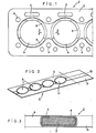
- the cylinder head gasket 2 shown in FIGS. 1 and 2 is constituted by a sealing plate 3 made of elastic and compressible material such as a possibly reinforced asbestos carton. It comprises orifices 4, generally circular, corresponding to the combustion chambers, orifices 5 intended for the passage of the engine cooling water and oil, as well as orifices 6 intended for the passage of the tightening holding studs of the breech.
- the orifices 4 are, as is known per se, surrounded by fittings 7 made of metal sheet, which constitute the rings of fire; they further comprise, according to the essential characteristic of the invention, reinforcements 8 located on the axis of least tightening and arranged on either side of the orifices 4. These reinforcements 8 are placed, as is clear in particular from the Figure 3, between the fire rings 7 and the plate 3, under each of the two faces of the rings.
- Figure 2 shows the metal sheet 9 from which the fire rings are made.
- This sheet which can be a sheet of copper, aluminum, stainless steel, aluminum clad steel, zinc-plated steel, tinned steel or other coated steels has in its central part and s extending over its entire length a reinforcement zone 10, corresponding to the zone of least tightening of the cylinder head gasket 2.
- This zone 10 possibly made integral with the sheet 9 by any means known per se, consists of a copper strip with a thickness of the order of 0.05 mm. It could also be a thin strip of brass, steel or aluminum.
- FIG. 2 shows the sheet metal 9 and reinforcement 10 complex after stamping ensuring the formation of generally circular orifices 11 with a diameter less than the diameter of the orifices 4 formed in the sealing plate 3.
- these orifices 11 are separated by reinforcement zones 10 arranged on either side of said orifices.
- the complex is cut out so as to provide bridges between the fire rings, then applied to the sealing plate 3 and crimped.
- the reinforcement 10 is then located inside the base crimped on either side of the sealing plate, covering the end of its upper and lower faces.
Description
La présente invention concerne un procédé de fabrication d'un joint de culasse pour moteur à combustion interne.The present invention relates to a method of manufacturing a cylinder head gasket for an internal combustion engine.
Les joints de culasse sont destinés à être placés entre un bloc moteur et une culasse en vue d'assurer l'étanchéité à divers fluides. C'est ainsi que le joint de culasse doit assurer l'étanchéité autour des orifices qui laissent passer des fluides tels que l'eau de refroidissement et l'huile qui circulent entre le bloc moteur et la culasse, et doit également assurer l'étanchéité aux gaz au niveau de la chambre de combustion de chacun des cylindres, nécessitant une résistance à des pressions et à des températures très élevées.The cylinder head gaskets are intended to be placed between an engine block and a cylinder head in order to ensure sealing against various fluids. This is how the cylinder head gasket must seal around the orifices which allow fluids such as cooling water and oil to circulate between the engine block and the cylinder head, and must also seal gases at the combustion chamber of each of the cylinders, requiring resistance to very high pressures and temperatures.
Cette fonction est remplie par des « anneaux de feu » obtenus par découpe, emboutissage et sertissage d'une tôle métallique sur le bord des orifices pratiqués dans le joint qui est pour sa part réalisé en un matériau élastique tel qu'un carton d'amiante armé ou non.This function is fulfilled by "fire rings" obtained by cutting, stamping and crimping a metal sheet on the edge of the orifices made in the joint which is for its part made of an elastic material such as asbestos cardboard armed or not.
On sait que cette étanchéité aux gaz dépend du serrage exercé sur les anneaux de feu du joint et que le serrage dans l'axe du moteur est en général plus faible que le serrage dans l'axe- travers en raison de la déformation de la culasse et des procédés d'usinage du bloc et de la culasse.We know that this gas tightness depends on the tightening exerted on the fire rings of the seal and that the tightening in the axis of the engine is generally weaker than the tightening in the transverse axis due to the deformation of the cylinder head. and methods of machining the block and the cylinder head.
On a déjà proposé d'améliorer cette étanchéité en bordant les ouvertures correspondantes des montures métalliques de garnitures annulaires. L'étanchéité obtenue, quoiqu'améliorée, ne donne toutefois pas entière satisfaction, pour les raisons ci-dessus, en raison des épaisseurs uniformes des garnitures sur le pourtour de l'anneau de feu.It has already been proposed to improve this sealing by bordering the corresponding openings of the metal frames of annular packings. The tightness obtained, although improved, is not entirely satisfactory, for the above reasons, due to the uniform thicknesses of the linings around the periphery of the fire ring.
Le brevet US-1 793424 décrit un joint de culasse comprenant une âme recouverte, sur toute sa surface et sur ses deux faces, par deux plaques métalliques, une plaque métallique inférieure et une plaque métallique supérieure. Au niveau de chaque ouverture correspondant à une chambre de combustion, la plaque subit des opérations d'emboutissage et de sertissage assurant la formation d'ailes formant les anneaux de feu.Patent US-1 793424 describes a cylinder head gasket comprising a core covered, over its entire surface and on its two faces, by two metal plates, a lower metal plate and an upper metal plate. At each opening corresponding to a combustion chamber, the plate undergoes stamping and crimping operations ensuring the formation of wings forming the rings of fire.
Dans la zone située entre deux cylindres, est disposé un insert métallique se présentant par exemple sous la forme d'une feuille de cuivre, comportant des ailes retournées sous les anneaux de feu.In the area between two cylinders, a metal insert is arranged, for example in the form of a copper foil, comprising wings turned upside down under the rings of fire.
Il est procédé au positionnement des inserts par rapport à l'âme puis à l'emboutissage des inserts pour former les ailes au niveau des ouvertures. La plaque de recouvrement supérieure étant alors positionnée, il est procédé à un sertissage des inserts pour former les ailes venant prendre appui sur la plaque. Il est alors procédé à la mise en place de la plaque de recouvrement inférieure qui subit à son tour des opérations d'emboutissage et de sertissage.The inserts are positioned relative to the core and then the stamping of the inserts to form the wings at the openings. The upper cover plate then being positioned, a crimping of the inserts is carried out to form the wings coming to bear on the plate. It then proceeds to the establishment of the lower cover plate which in turn undergoes stamping and crimping operations.
Ce procédé présente les inconvénients suivants :
- - multiplicité des opérations qui doivent être effectuées manuellement et notamment positionnement des inserts entre deux cylindres adjacents ;
- - le positionnement de chaque insert est effectué de façon approximative, ce qui risque de se traduire par des défauts d'étanchéité ;
- - mise en oeuvre d'un joint comportant une âme et deux plaques de recouvrement, solution qui n'est presque plus utilisée en pratique de nos jours ;
- - compte tenu de la structure des renforts, ceux-ci ne peuvent être placés que dans la zone comprise entre deux cylindres, mais non au niveau des zones des anneaux de feu situées aux extrémités du joint ; or, de nombreux moteurs modernes exigent un renfort aux extrémités ;
- - nécessité de recouvrement d'une des faces du joint sur toute la zone comprise entre deux ouvertures de celui-ci ; si cette zone est de largeur importante, le serrage exercé à son niveau sera effectué au détriment du serrage au niveau des anneaux de feu.
- - multiplicity of operations which must be carried out manually and in particular positioning of the inserts between two adjacent cylinders;
- the positioning of each insert is carried out approximately, which may result in leaks;
- - implementation of a joint comprising a core and two cover plates, a solution which is almost no longer used in practice today;
- - taking into account the structure of the reinforcements, these can only be placed in the zone between two cylinders, but not at the level of the zones of the fire rings situated at the ends of the joint; many modern engines require reinforcement at the ends;
- - need to cover one of the faces of the joint over the entire area between two openings thereof; if this zone is of significant width, the tightening exerted at its level will be carried out to the detriment of the tightening at the level of the rings of fire.
La présente invention vise à remédier à ces inconvénients.The present invention aims to remedy these drawbacks.
A cet effet, le procédé de fabrication d'un joint de culasse qu'elle concerne, comportant une plaque d'étanchéité en matériau élastique tel qu'un carton d'amiante armé ou non et des anneaux de feu obtenus par découpe, emboutissage et sertissage d'une tôle métallique sur le bord des orifices pratiqués dans la plaque d'étanchéité, des renforts étant prévus entre les. anneaux et la plaque, localisés dans la zone de moindre serrage des anneaux de feu et réalisés en un matériau résistant aux températures et pressions exercées dans cette zone du moteur, dans lequel les renforts sont disposés sous chacune des deux faces des anneaux de feu et sont obtenus à partir d'une pièce de matière différente de celle à partir de laquelle sont réalisés les anneaux de feu, et constituée par un feuillard métallique mince en cuivre, laiton, acier ou aluminium appliqué sur la face de la tôle métallique correspondant à l'intérieur du serti formant chaque anneau de feu, est caractérisé en ce qu'il consiste à solidariser le feuillard formant les renforts et la tôle formant les anneaux de feu, à emboutir et sertir autour des orifices de la plaque d'étanchéité, en même temps le feuillard et la tôle.To this end, the process for manufacturing a cylinder head gasket which it relates to, comprising a sealing plate made of elastic material such as a cardboard box of asbestos, armed or not, and fire rings obtained by cutting, stamping and crimping of a metal sheet on the edge of the orifices made in the sealing plate, reinforcements being provided between the. rings and plate, located in the area of least tightening of the fire rings and made of a material resistant to the temperatures and pressures exerted in this area of the engine, in which the reinforcements are arranged under each of the two faces of the fire rings and are obtained from a piece of material different from that from which the fire rings are made, and constituted by a thin metal strip of copper, brass, steel or aluminum applied to the face of the metal sheet corresponding to the inside of the setting forming each fire ring, is characterized in that it consists in joining the strip forming the reinforcements and the sheet forming the fire rings, to stamp and crimp around the orifices of the sealing plate, at the same time the strip and the sheet metal.
Ce procédé présente les avantages suivants :
- - simplicité de mise en oeuvre puisqu'après solidarisation de la tôle dans laquelle sont ultérieurement formés les anneaux de feu et le feuillard de renfort, toutes les opérations sont effectuées comme si la tôle était mise en œuvre toute seule ;
- - il en résulte une, réduction du nombre d'opérations et un parfait positionnement des renforts par rapport aux anneaux de feu ;
- - si besoin est, les renforts peuvent également être localisés du côté des extrémités du joint ;
- - ces renforts peuvent être appliqués à des joints dont l'âme est revêtue ou non de deux plaques métalliques sur ses deux faces ;
- - suivant l'application envisagée, le complexe tôle + feuillard de renforcement peut être monté de façon unitaire sur une garniture d'étanchéité, ou bien les différents anneaux de feu et leurs renforts peuvent être désolidarisés les uns des autres ; dans ce dernier cas, les renforts ne s'étendent pas dans la zone comprise entre deux anneaux de feu adjacents, de telle sorte que le serrage peut être concentré sur ces derniers, ce qui parfait l'étanchéité.
- - Simplicity of implementation since after joining of the sheet in which the fire rings and the reinforcing strip are subsequently formed, all the operations are carried out as if the sheet were implemented all alone;
- - This results in a reduction in the number of operations and a perfect positioning of the reinforcements relative to the fire rings;
- - if necessary, reinforcements can also be located on the end of the joint side;
- - These reinforcements can be applied to joints whose core is coated or not with two metal plates on its two faces;
- - Depending on the application envisaged, the sheet + reinforcement strip complex can be mounted as a unit on a seal, or else the various fire rings and their reinforcements can be separated from one another; in the latter case, the reinforcements do not extend in the area between two adjacent fire rings, so that the clamping can be concentrated on the latter, which perfect sealing.
Selon un mode de mise en oeuvre, ce procédé consiste à solidariser par collage le feuillard formant les renforts et la tôle formant les anneaux de feu.According to one embodiment, this process consists of joining the strip forming the reinforcements and the sheet metal forming the fire rings by bonding.
Avantageusement le feuillard métallique possède une épaisseur comprise entre 0,02 et 0,15 mm.Advantageously, the metal strip has a thickness of between 0.02 and 0.15 mm.
La présente invention sera mieux comprise d'ailleurs et ses avantages ressortiront bien de la description qui suit en référence au dessin schématique annexé représentant, à titre d'exemple non limitatif, une forme d'exécution d'un joint de culasse à renforts localisés :
- Figure 1 est une vue de dessous d'un joint de culasse à anneaux muftiples ;
- Figure 2 est une vue en perspective de la tôle métallique permettant la réalisation des anneaux de feu ;
- Figure 3 est une vue en coupe et à échelle agrandie d'un détail de ce joint selon la ligne 3-3 de figure 1.
- Figure 1 is a bottom view of a multiple ring cylinder head gasket;
- Figure 2 is a perspective view of the metal sheet for the production of fire rings;
- Figure 3 is a sectional view on an enlarged scale of a detail of this joint along line 3-3 of Figure 1.
Le joint de culasse 2 représenté aux figures 1 et 2 est constitué par une plaque d'étanchéité 3 en matériau élastique et compressible tel qu'un carton d'amiante éventuellement renforcé. Il comporte des orifices 4, généralement circulaires, correspondant aux chambres de combustion, des orifices 5 destinés au passage de l'eau de refroidissement du moteur et de l'huile, ainsi que des orifices 6 destinés au passage des goujons de maintien de serrage de la culasse.The
Les orifices 4 sont, comme il est connu en soi, entourés de garnitures 7 en tôle métallique, qui constituent les anneaux de feu ; ils comportent, en outre, selon la caractéristique essentielle de l'invention, des renforts 8 localisés sur l'axe de moindre serrage et disposés de part et d'autre des orifices 4. Ces renforts 8 sont placés, comme il ressort notamment de la figure 3, entre les anneaux de feu 7 et la plaque 3, sous chacune des deux faces des anneaux.The
La figure 2 montre la tôle métallique 9 à partir de laquelle sont réalisés les anneaux de feu. Cette tôle, qui peut être une tôle de cuivre, d'aluminium, d'acier inoxydable, d'acier plaqué d'aluminium, d'acier zingué, d'acier étamé ou d'autres aciers revêtus comporte en sa partie centrale et s'étendant sur toute sa longueur une zone de renfort 10, correspondant à la zone de moindre serrage du joint de culasse 2.Figure 2 shows the metal sheet 9 from which the fire rings are made. This sheet, which can be a sheet of copper, aluminum, stainless steel, aluminum clad steel, zinc-plated steel, tinned steel or other coated steels has in its central part and s extending over its entire length a
Cette zone 10, rendue éventuellement solidaire de la tôle 9 par tout moyen connu en soi, est constituée par un feuillard de cuivre d'une épaisseur de l'ordre de 0,05 mm. Il pourrait s'agir également d'un feuillard mince en laiton, acier ou aluminium.This
La partie gauche de la figure 2 montre le complexe tôle 9 et renfort 10 après emboutissage assurant la formation d'orifices généralement circulaires 11 de diamètre inférieur au diamètre des orifices 4 ménagés dans la plaque d'étanchéité 3.The left part of FIG. 2 shows the sheet metal 9 and
Comme on le voit sur la figure 2, ces orifices 11 sont séparés par des zones de renfort 10 disposées de part et d'autre des dits orifices.As can be seen in FIG. 2, these
Le complexe est détouré de manière à ménager des pontages entre les anneaux de feu,puis appliqué sur la plaque d'étanchéité 3 et serti. Le renfort 10 se trouve alors à l'intérieur du culot serti de part et d'autre de la plaque d'étanchéité, recouvrant l'extrémité de ses faces supérieure et inférieure.The complex is cut out so as to provide bridges between the fire rings, then applied to the sealing
Claims (3)
Applications Claiming Priority (2)
| Application Number | Priority Date | Filing Date | Title |
|---|---|---|---|
| FR7927394 | 1979-10-31 | ||
| FR7927394A FR2468801A1 (en) | 1979-10-31 | 1979-10-31 | HEAD GASKET FOR INTERNAL COMBUSTION ENGINE |
Publications (3)
| Publication Number | Publication Date |
|---|---|
| EP0028576A1 EP0028576A1 (en) | 1981-05-13 |
| EP0028576B1 EP0028576B1 (en) | 1983-04-13 |
| EP0028576B2 true EP0028576B2 (en) | 1986-09-10 |
Family
ID=9231360
Family Applications (1)
| Application Number | Title | Priority Date | Filing Date |
|---|---|---|---|
| EP80420106A Expired EP0028576B2 (en) | 1979-10-31 | 1980-09-22 | Head gasket for an internal-combustion engine |
Country Status (7)
| Country | Link |
|---|---|
| US (1) | US4330585A (en) |
| EP (1) | EP0028576B2 (en) |
| JP (1) | JPS5677536A (en) |
| DE (1) | DE3062760D1 (en) |
| ES (1) | ES8106046A1 (en) |
| FR (1) | FR2468801A1 (en) |
| PT (1) | PT71930B (en) |
Families Citing this family (16)
| Publication number | Priority date | Publication date | Assignee | Title |
|---|---|---|---|---|
| DE3314237A1 (en) * | 1983-04-20 | 1984-10-31 | Goetze Ag, 5093 Burscheid | CYLINDER HEAD GASKET |
| DE3425075A1 (en) * | 1984-07-07 | 1986-01-16 | Goetze Ag, 5093 Burscheid | Cylinder head gasket for internal combustion engines and a method for its production |
| US4653761A (en) * | 1985-06-28 | 1987-03-31 | Cummins Engine Company, Inc. | Coolant flow orificing head gasket |
| DE3533359A1 (en) * | 1985-09-19 | 1987-03-26 | Lechler Elring Dichtungswerke | CYLINDER HEAD GASKET |
| US4662643A (en) * | 1986-04-14 | 1987-05-05 | Felt Products Mfg. Co. | Head gasket assembly for closely adjacent cylinder bores and method of making same |
| US4767124A (en) * | 1986-07-29 | 1988-08-30 | Ishikawa Gasket Co., Ltd. | Gasket for an internal combustion engine |
| JPH067216Y2 (en) * | 1986-07-29 | 1994-02-23 | 石川ガスケット株式会社 | Metal non-metal composite type gasket for cylinder head |
| US4815750A (en) * | 1988-06-08 | 1989-03-28 | Nihon Metal Gasket Kabushiki Kaisha | Metallic gasket with sealing beads |
| DE3922284A1 (en) * | 1989-07-06 | 1991-01-17 | Reinz Dichtungs Gmbh | CYLINDER HEAD GASKET |
| FR2667358B1 (en) * | 1990-10-01 | 1994-12-23 | Meillor Sa | DOUBLE CRIMPED HEAD GASKET. |
| JP2989282B2 (en) * | 1991-01-09 | 1999-12-13 | 日本ガスケット株式会社 | Metal gasket |
| US5297806A (en) * | 1991-08-08 | 1994-03-29 | Dana Corporation | Method of making multi-density composite gaskets |
| CA2080103A1 (en) * | 1991-11-13 | 1993-05-14 | Joseph A. Pecina | Aluminum core cylinder head gasket for marine engines |
| GB2279895B (en) * | 1993-07-15 | 1996-03-06 | T & N Technology Ltd | Forming eyelets in gaskets |
| US5895057A (en) * | 1997-03-17 | 1999-04-20 | Fel-Pro Incorporated | Head gasket assembly for very closely adjacent cylinder bores with stabilized armoring and method of making same |
| US6669204B2 (en) | 2002-03-25 | 2003-12-30 | Federal-Mogul World Wide, Inc. | Cylinder head gasket having reinforced combustion seal |
Family Cites Families (8)
| Publication number | Priority date | Publication date | Assignee | Title |
|---|---|---|---|---|
| US1864854A (en) * | 1931-04-29 | 1932-06-28 | Victor Mfg & Gasket Co | Gasket |
| US2001225A (en) * | 1934-01-17 | 1935-05-14 | Victor Mfg & Gasket Co | Skeleton metal-backed gasket |
| DE2347321A1 (en) * | 1973-09-20 | 1975-03-27 | Goetzewerke | FLAT GASKET, IN PARTICULAR CYLINDER HEAD GASKET |
| JPS5425533Y2 (en) * | 1975-10-17 | 1979-08-25 | ||
| US4049856A (en) * | 1976-10-16 | 1977-09-20 | Tba Industrial Products Limited | Gaskets |
| US4272085A (en) * | 1978-10-07 | 1981-06-09 | Kawasaki Jukogyo Kabushiki Kaisha | Cylinder head gasket for a liquid cooled internal combustion engine |
| US4243231A (en) * | 1979-08-10 | 1981-01-06 | Ishino Gasket Mfg. Co., Ltd. | Gasket reinforced by grommet in combination with graphite sheet |
| US4254963A (en) * | 1979-12-04 | 1981-03-10 | Ex-Cell-O Corporation | Gasket assembly |
-
1979
- 1979-10-31 FR FR7927394A patent/FR2468801A1/en active Granted
-
1980
- 1980-09-22 DE DE8080420106T patent/DE3062760D1/en not_active Expired
- 1980-09-22 EP EP80420106A patent/EP0028576B2/en not_active Expired
- 1980-10-07 ES ES495681A patent/ES8106046A1/en not_active Expired
- 1980-10-17 PT PT71930A patent/PT71930B/en unknown
- 1980-10-30 US US06/202,233 patent/US4330585A/en not_active Expired - Lifetime
- 1980-10-30 JP JP15150780A patent/JPS5677536A/en active Pending
Also Published As
| Publication number | Publication date |
|---|---|
| FR2468801B1 (en) | 1982-02-19 |
| ES495681A0 (en) | 1981-07-01 |
| JPS5677536A (en) | 1981-06-25 |
| EP0028576B1 (en) | 1983-04-13 |
| DE3062760D1 (en) | 1983-05-19 |
| PT71930B (en) | 1981-08-31 |
| ES8106046A1 (en) | 1981-07-01 |
| US4330585A (en) | 1982-05-18 |
| PT71930A (en) | 1980-11-01 |
| EP0028576A1 (en) | 1981-05-13 |
| FR2468801A1 (en) | 1981-05-08 |
Similar Documents
| Publication | Publication Date | Title |
|---|---|---|
| EP0028576B2 (en) | Head gasket for an internal-combustion engine | |
| EP1023549B1 (en) | Static sealing joint | |
| EP0086727B1 (en) | Cylinder head gasket for an internal-combustion engine | |
| EP0165879B1 (en) | Cylinder head gasket | |
| FR2751029A1 (en) | Silencer for motor vehicle internal combustion engine exhaust | |
| EP0310528B1 (en) | Cylinder head gasket for an internal-combustion engine | |
| EP1521019B1 (en) | Multi-layered gasket with at least a thickening shim | |
| FR2742529A1 (en) | HEAT EXCHANGER WITH A SET COLLECTOR PLATE, PARTICULARLY FOR A MOTOR VEHICLE | |
| FR2737255A1 (en) | HEAD GASKET FOR INTERNAL COMBUSTION ENGINE | |
| FR2736681A1 (en) | JOINT FOR INTERNAL COMBUSTION ENGINE, IN PARTICULAR JOINT OF CYLINDER HEAD | |
| EP0499551B1 (en) | Cylinder head gasket for internal combustion engine | |
| EP2255146B1 (en) | Grooveless header plate | |
| FR2710104A1 (en) | Method of manufacturing a rocker arm shaft for internal combustion engines | |
| EP0939209A2 (en) | Metal gasket seal for the exhaust gas line of an internal combustion engine | |
| EP0048666B1 (en) | Method of fixing a shell to a sole-plate of a steam iron, shell therefor and iron | |
| EP0487369A1 (en) | Internal combustion engine with cylinder head gasket | |
| FR2524110A1 (en) | METHOD OF MANUFACTURING A TUBE WITH CONDUITS PLACED IN ITS WALL | |
| FR2852543A1 (en) | Connection support fixing process for heat exchanger e.g. air-conditioning condenser, involves deforming wall to penetrate hole for connection by mechanical clinching operation and brazing support with lid | |
| FR2484533A1 (en) | Compensating tank for cooling water - consists of plastics body incorporating all connections between two covers with reinforcing ribs | |
| FR2574891A1 (en) | Method of making a seal comprising a metal support | |
| EP0082090B1 (en) | Cylinder head gasket for an internal combustion engine with precombustion chamber | |
| FR2758591A1 (en) | IC engine cylinder block, especially for Diesel engines | |
| FR2742534A1 (en) | Automobile heat exchanger | |
| FR2921431A3 (en) | Cylinder head gasket for internal combustion engine, has ribbed upper and lower sheets welded on sides of plate around cylinder for providing sealing to combustion gas in cylinder, where plate forms armature of gasket | |
| FR2602006A1 (en) | Cylinder head gasket for an internal combustion engine |
Legal Events
| Date | Code | Title | Description |
|---|---|---|---|
| PUAI | Public reference made under article 153(3) epc to a published international application that has entered the european phase |
Free format text: ORIGINAL CODE: 0009012 |
|
| ITCL | It: translation for ep claims filed |
Representative=s name: JACOBACCI CASETTA & PERANI S.P.A. |
|
| AK | Designated contracting states |
Designated state(s): BE DE GB IT NL SE |
|
| 17P | Request for examination filed |
Effective date: 19810323 |
|
| DET | De: translation of patent claims | ||
| ITF | It: translation for a ep patent filed |
Owner name: JACOBACCI & PERANI S.P.A. |
|
| GRAA | (expected) grant |
Free format text: ORIGINAL CODE: 0009210 |
|
| AK | Designated contracting states |
Designated state(s): BE DE GB IT NL SE |
|
| REF | Corresponds to: |
Ref document number: 3062760 Country of ref document: DE Date of ref document: 19830519 |
|
| PLBI | Opposition filed |
Free format text: ORIGINAL CODE: 0009260 |
|
| 26 | Opposition filed |
Opponent name: GOETZE AG Effective date: 19831008 |
|
| PLBI | Opposition filed |
Free format text: ORIGINAL CODE: 0009260 |
|
| 26 | Opposition filed |
Opponent name: ELRING DICHTUNGSWERKE GMBH Effective date: 19840107 |
|
| PGFP | Annual fee paid to national office [announced via postgrant information from national office to epo] |
Ref country code: DE Payment date: 19840803 Year of fee payment: 5 |
|
| PGFP | Annual fee paid to national office [announced via postgrant information from national office to epo] |
Ref country code: SE Payment date: 19840930 Year of fee payment: 5 Ref country code: BE Payment date: 19840930 Year of fee payment: 5 |
|
| PUAH | Patent maintained in amended form |
Free format text: ORIGINAL CODE: 0009272 |
|
| STAA | Information on the status of an ep patent application or granted ep patent |
Free format text: STATUS: PATENT MAINTAINED AS AMENDED |
|
| 27A | Patent maintained in amended form |
Effective date: 19860910 |
|
| AK | Designated contracting states |
Kind code of ref document: B2 Designated state(s): BE DE GB IT NL SE |
|
| ITF | It: translation for a ep patent filed |
Owner name: JACOBACCI & PERANI S.P.A. |
|
| PGFP | Annual fee paid to national office [announced via postgrant information from national office to epo] |
Ref country code: NL Payment date: 19860930 Year of fee payment: 7 |
|
| NLR2 | Nl: decision of opposition | ||
| NLR3 | Nl: receipt of modified translations in the netherlands language after an opposition procedure | ||
| PG25 | Lapsed in a contracting state [announced via postgrant information from national office to epo] |
Ref country code: SE Effective date: 19870923 |
|
| PG25 | Lapsed in a contracting state [announced via postgrant information from national office to epo] |
Ref country code: BE Effective date: 19870930 |
|
| BERE | Be: lapsed |
Effective date: 19870930 |
|
| PG25 | Lapsed in a contracting state [announced via postgrant information from national office to epo] |
Ref country code: NL Effective date: 19880401 |
|
| NLV4 | Nl: lapsed or anulled due to non-payment of the annual fee | ||
| PG25 | Lapsed in a contracting state [announced via postgrant information from national office to epo] |
Ref country code: DE Effective date: 19880601 |
|
| GBPC | Gb: european patent ceased through non-payment of renewal fee | ||
| PG25 | Lapsed in a contracting state [announced via postgrant information from national office to epo] |
Ref country code: GB Free format text: LAPSE BECAUSE OF NON-PAYMENT OF DUE FEES Effective date: 19881118 |
|
| EUG | Se: european patent has lapsed |
Ref document number: 80420106.9 Effective date: 19880906 |