EP1555457B1 - Nockenvorrichtung - Google Patents
Nockenvorrichtung Download PDFInfo
- Publication number
- EP1555457B1 EP1555457B1 EP02777931A EP02777931A EP1555457B1 EP 1555457 B1 EP1555457 B1 EP 1555457B1 EP 02777931 A EP02777931 A EP 02777931A EP 02777931 A EP02777931 A EP 02777931A EP 1555457 B1 EP1555457 B1 EP 1555457B1
- Authority
- EP
- European Patent Office
- Prior art keywords
- rotation
- output shaft
- cam
- input shaft
- lifting
- Prior art date
- Legal status (The legal status is an assumption and is not a legal conclusion. Google has not performed a legal analysis and makes no representation as to the accuracy of the status listed.)
- Expired - Lifetime
Links
Images







Classifications
-
- F—MECHANICAL ENGINEERING; LIGHTING; HEATING; WEAPONS; BLASTING
- F16—ENGINEERING ELEMENTS AND UNITS; GENERAL MEASURES FOR PRODUCING AND MAINTAINING EFFECTIVE FUNCTIONING OF MACHINES OR INSTALLATIONS; THERMAL INSULATION IN GENERAL
- F16H—GEARING
- F16H37/00—Combinations of mechanical gearings, not provided for in groups F16H1/00 - F16H35/00
- F16H37/12—Gearings comprising primarily toothed or friction gearing, links or levers, and cams, or members of at least two of these types
- F16H37/16—Gearings comprising primarily toothed or friction gearing, links or levers, and cams, or members of at least two of these types with a driving or driven member which both rotates or oscillates on its axis and reciprocates
-
- B—PERFORMING OPERATIONS; TRANSPORTING
- B23—MACHINE TOOLS; METAL-WORKING NOT OTHERWISE PROVIDED FOR
- B23Q—DETAILS, COMPONENTS, OR ACCESSORIES FOR MACHINE TOOLS, e.g. ARRANGEMENTS FOR COPYING OR CONTROLLING; MACHINE TOOLS IN GENERAL CHARACTERISED BY THE CONSTRUCTION OF PARTICULAR DETAILS OR COMPONENTS; COMBINATIONS OR ASSOCIATIONS OF METAL-WORKING MACHINES, NOT DIRECTED TO A PARTICULAR RESULT
- B23Q7/00—Arrangements for handling work specially combined with or arranged in, or specially adapted for use in connection with, machine tools, e.g. for conveying, loading, positioning, discharging, sorting
-
- B—PERFORMING OPERATIONS; TRANSPORTING
- B23—MACHINE TOOLS; METAL-WORKING NOT OTHERWISE PROVIDED FOR
- B23Q—DETAILS, COMPONENTS, OR ACCESSORIES FOR MACHINE TOOLS, e.g. ARRANGEMENTS FOR COPYING OR CONTROLLING; MACHINE TOOLS IN GENERAL CHARACTERISED BY THE CONSTRUCTION OF PARTICULAR DETAILS OR COMPONENTS; COMBINATIONS OR ASSOCIATIONS OF METAL-WORKING MACHINES, NOT DIRECTED TO A PARTICULAR RESULT
- B23Q1/00—Members which are comprised in the general build-up of a form of machine, particularly relatively large fixed members
- B23Q1/25—Movable or adjustable work or tool supports
- B23Q1/44—Movable or adjustable work or tool supports using particular mechanisms
- B23Q1/48—Movable or adjustable work or tool supports using particular mechanisms with sliding pairs and rotating pairs
-
- B—PERFORMING OPERATIONS; TRANSPORTING
- B23—MACHINE TOOLS; METAL-WORKING NOT OTHERWISE PROVIDED FOR
- B23Q—DETAILS, COMPONENTS, OR ACCESSORIES FOR MACHINE TOOLS, e.g. ARRANGEMENTS FOR COPYING OR CONTROLLING; MACHINE TOOLS IN GENERAL CHARACTERISED BY THE CONSTRUCTION OF PARTICULAR DETAILS OR COMPONENTS; COMBINATIONS OR ASSOCIATIONS OF METAL-WORKING MACHINES, NOT DIRECTED TO A PARTICULAR RESULT
- B23Q16/00—Equipment for precise positioning of tool or work into particular locations not otherwise provided for
- B23Q16/02—Indexing equipment
- B23Q16/022—Indexing equipment in which only the indexing movement is of importance
- B23Q16/024—Indexing equipment in which only the indexing movement is of importance and by converting a continuous movement into a linear indexing movement
-
- B—PERFORMING OPERATIONS; TRANSPORTING
- B23—MACHINE TOOLS; METAL-WORKING NOT OTHERWISE PROVIDED FOR
- B23Q—DETAILS, COMPONENTS, OR ACCESSORIES FOR MACHINE TOOLS, e.g. ARRANGEMENTS FOR COPYING OR CONTROLLING; MACHINE TOOLS IN GENERAL CHARACTERISED BY THE CONSTRUCTION OF PARTICULAR DETAILS OR COMPONENTS; COMBINATIONS OR ASSOCIATIONS OF METAL-WORKING MACHINES, NOT DIRECTED TO A PARTICULAR RESULT
- B23Q16/00—Equipment for precise positioning of tool or work into particular locations not otherwise provided for
- B23Q16/02—Indexing equipment
- B23Q16/022—Indexing equipment in which only the indexing movement is of importance
- B23Q16/025—Indexing equipment in which only the indexing movement is of importance by converting a continuous movement into a rotary indexing movement
-
- B—PERFORMING OPERATIONS; TRANSPORTING
- B23—MACHINE TOOLS; METAL-WORKING NOT OTHERWISE PROVIDED FOR
- B23Q—DETAILS, COMPONENTS, OR ACCESSORIES FOR MACHINE TOOLS, e.g. ARRANGEMENTS FOR COPYING OR CONTROLLING; MACHINE TOOLS IN GENERAL CHARACTERISED BY THE CONSTRUCTION OF PARTICULAR DETAILS OR COMPONENTS; COMBINATIONS OR ASSOCIATIONS OF METAL-WORKING MACHINES, NOT DIRECTED TO A PARTICULAR RESULT
- B23Q16/00—Equipment for precise positioning of tool or work into particular locations not otherwise provided for
- B23Q16/02—Indexing equipment
- B23Q16/04—Indexing equipment having intermediate members, e.g. pawls, for locking the relatively movable parts in the indexed position
- B23Q16/06—Rotary indexing
- B23Q16/065—Rotary indexing with a continuous drive
-
- B—PERFORMING OPERATIONS; TRANSPORTING
- B23—MACHINE TOOLS; METAL-WORKING NOT OTHERWISE PROVIDED FOR
- B23Q—DETAILS, COMPONENTS, OR ACCESSORIES FOR MACHINE TOOLS, e.g. ARRANGEMENTS FOR COPYING OR CONTROLLING; MACHINE TOOLS IN GENERAL CHARACTERISED BY THE CONSTRUCTION OF PARTICULAR DETAILS OR COMPONENTS; COMBINATIONS OR ASSOCIATIONS OF METAL-WORKING MACHINES, NOT DIRECTED TO A PARTICULAR RESULT
- B23Q3/00—Devices holding, supporting, or positioning work or tools, of a kind normally removable from the machine
- B23Q3/155—Arrangements for automatic insertion or removal of tools, e.g. combined with manual handling
- B23Q3/1552—Arrangements for automatic insertion or removal of tools, e.g. combined with manual handling parts of devices for automatically inserting or removing tools
- B23Q3/1554—Transfer mechanisms, e.g. tool gripping arms; Drive mechanisms therefore
-
- B—PERFORMING OPERATIONS; TRANSPORTING
- B23—MACHINE TOOLS; METAL-WORKING NOT OTHERWISE PROVIDED FOR
- B23Q—DETAILS, COMPONENTS, OR ACCESSORIES FOR MACHINE TOOLS, e.g. ARRANGEMENTS FOR COPYING OR CONTROLLING; MACHINE TOOLS IN GENERAL CHARACTERISED BY THE CONSTRUCTION OF PARTICULAR DETAILS OR COMPONENTS; COMBINATIONS OR ASSOCIATIONS OF METAL-WORKING MACHINES, NOT DIRECTED TO A PARTICULAR RESULT
- B23Q5/00—Driving or feeding mechanisms; Control arrangements therefor
- B23Q5/22—Feeding members carrying tools or work
- B23Q5/34—Feeding other members supporting tools or work, e.g. saddles, tool-slides, through mechanical transmission
- B23Q5/341—Feeding other members supporting tools or work, e.g. saddles, tool-slides, through mechanical transmission cam-operated
- B23Q5/347—Feeding other members supporting tools or work, e.g. saddles, tool-slides, through mechanical transmission cam-operated controlled in conjunction with tool or work indexing means
-
- B—PERFORMING OPERATIONS; TRANSPORTING
- B23—MACHINE TOOLS; METAL-WORKING NOT OTHERWISE PROVIDED FOR
- B23Q—DETAILS, COMPONENTS, OR ACCESSORIES FOR MACHINE TOOLS, e.g. ARRANGEMENTS FOR COPYING OR CONTROLLING; MACHINE TOOLS IN GENERAL CHARACTERISED BY THE CONSTRUCTION OF PARTICULAR DETAILS OR COMPONENTS; COMBINATIONS OR ASSOCIATIONS OF METAL-WORKING MACHINES, NOT DIRECTED TO A PARTICULAR RESULT
- B23Q7/00—Arrangements for handling work specially combined with or arranged in, or specially adapted for use in connection with, machine tools, e.g. for conveying, loading, positioning, discharging, sorting
- B23Q7/02—Arrangements for handling work specially combined with or arranged in, or specially adapted for use in connection with, machine tools, e.g. for conveying, loading, positioning, discharging, sorting by means of drums or rotating tables or discs
-
- B—PERFORMING OPERATIONS; TRANSPORTING
- B23—MACHINE TOOLS; METAL-WORKING NOT OTHERWISE PROVIDED FOR
- B23Q—DETAILS, COMPONENTS, OR ACCESSORIES FOR MACHINE TOOLS, e.g. ARRANGEMENTS FOR COPYING OR CONTROLLING; MACHINE TOOLS IN GENERAL CHARACTERISED BY THE CONSTRUCTION OF PARTICULAR DETAILS OR COMPONENTS; COMBINATIONS OR ASSOCIATIONS OF METAL-WORKING MACHINES, NOT DIRECTED TO A PARTICULAR RESULT
- B23Q7/00—Arrangements for handling work specially combined with or arranged in, or specially adapted for use in connection with, machine tools, e.g. for conveying, loading, positioning, discharging, sorting
- B23Q7/14—Arrangements for handling work specially combined with or arranged in, or specially adapted for use in connection with, machine tools, e.g. for conveying, loading, positioning, discharging, sorting co-ordinated in production lines
- B23Q7/1426—Arrangements for handling work specially combined with or arranged in, or specially adapted for use in connection with, machine tools, e.g. for conveying, loading, positioning, discharging, sorting co-ordinated in production lines with work holders not rigidly fixed to the transport devices
- B23Q7/1431—Work holder changers
-
- B—PERFORMING OPERATIONS; TRANSPORTING
- B23—MACHINE TOOLS; METAL-WORKING NOT OTHERWISE PROVIDED FOR
- B23Q—DETAILS, COMPONENTS, OR ACCESSORIES FOR MACHINE TOOLS, e.g. ARRANGEMENTS FOR COPYING OR CONTROLLING; MACHINE TOOLS IN GENERAL CHARACTERISED BY THE CONSTRUCTION OF PARTICULAR DETAILS OR COMPONENTS; COMBINATIONS OR ASSOCIATIONS OF METAL-WORKING MACHINES, NOT DIRECTED TO A PARTICULAR RESULT
- B23Q3/00—Devices holding, supporting, or positioning work or tools, of a kind normally removable from the machine
- B23Q3/155—Arrangements for automatic insertion or removal of tools, e.g. combined with manual handling
- B23Q3/1552—Arrangements for automatic insertion or removal of tools, e.g. combined with manual handling parts of devices for automatically inserting or removing tools
- B23Q3/1554—Transfer mechanisms, e.g. tool gripping arms; Drive mechanisms therefore
- B23Q2003/155414—Transfer mechanisms, e.g. tool gripping arms; Drive mechanisms therefore the transfer mechanism comprising two or more grippers
- B23Q2003/155418—Transfer mechanisms, e.g. tool gripping arms; Drive mechanisms therefore the transfer mechanism comprising two or more grippers the grippers moving together
-
- B—PERFORMING OPERATIONS; TRANSPORTING
- B23—MACHINE TOOLS; METAL-WORKING NOT OTHERWISE PROVIDED FOR
- B23Q—DETAILS, COMPONENTS, OR ACCESSORIES FOR MACHINE TOOLS, e.g. ARRANGEMENTS FOR COPYING OR CONTROLLING; MACHINE TOOLS IN GENERAL CHARACTERISED BY THE CONSTRUCTION OF PARTICULAR DETAILS OR COMPONENTS; COMBINATIONS OR ASSOCIATIONS OF METAL-WORKING MACHINES, NOT DIRECTED TO A PARTICULAR RESULT
- B23Q3/00—Devices holding, supporting, or positioning work or tools, of a kind normally removable from the machine
- B23Q3/155—Arrangements for automatic insertion or removal of tools, e.g. combined with manual handling
- B23Q3/1552—Arrangements for automatic insertion or removal of tools, e.g. combined with manual handling parts of devices for automatically inserting or removing tools
- B23Q3/1554—Transfer mechanisms, e.g. tool gripping arms; Drive mechanisms therefore
- B23Q2003/155414—Transfer mechanisms, e.g. tool gripping arms; Drive mechanisms therefore the transfer mechanism comprising two or more grippers
- B23Q2003/155425—Transfer mechanisms, e.g. tool gripping arms; Drive mechanisms therefore the transfer mechanism comprising two or more grippers pivotable
- B23Q2003/155428—Transfer mechanisms, e.g. tool gripping arms; Drive mechanisms therefore the transfer mechanism comprising two or more grippers pivotable about a common axis
-
- B—PERFORMING OPERATIONS; TRANSPORTING
- B23—MACHINE TOOLS; METAL-WORKING NOT OTHERWISE PROVIDED FOR
- B23Q—DETAILS, COMPONENTS, OR ACCESSORIES FOR MACHINE TOOLS, e.g. ARRANGEMENTS FOR COPYING OR CONTROLLING; MACHINE TOOLS IN GENERAL CHARACTERISED BY THE CONSTRUCTION OF PARTICULAR DETAILS OR COMPONENTS; COMBINATIONS OR ASSOCIATIONS OF METAL-WORKING MACHINES, NOT DIRECTED TO A PARTICULAR RESULT
- B23Q3/00—Devices holding, supporting, or positioning work or tools, of a kind normally removable from the machine
- B23Q3/155—Arrangements for automatic insertion or removal of tools, e.g. combined with manual handling
- B23Q3/1552—Arrangements for automatic insertion or removal of tools, e.g. combined with manual handling parts of devices for automatically inserting or removing tools
- B23Q3/1554—Transfer mechanisms, e.g. tool gripping arms; Drive mechanisms therefore
- B23Q2003/155414—Transfer mechanisms, e.g. tool gripping arms; Drive mechanisms therefore the transfer mechanism comprising two or more grippers
- B23Q2003/155425—Transfer mechanisms, e.g. tool gripping arms; Drive mechanisms therefore the transfer mechanism comprising two or more grippers pivotable
- B23Q2003/155435—Transfer mechanisms, e.g. tool gripping arms; Drive mechanisms therefore the transfer mechanism comprising two or more grippers pivotable and linearly movable
- B23Q2003/155439—Transfer mechanisms, e.g. tool gripping arms; Drive mechanisms therefore the transfer mechanism comprising two or more grippers pivotable and linearly movable along the pivoting axis
-
- F—MECHANICAL ENGINEERING; LIGHTING; HEATING; WEAPONS; BLASTING
- F16—ENGINEERING ELEMENTS AND UNITS; GENERAL MEASURES FOR PRODUCING AND MAINTAINING EFFECTIVE FUNCTIONING OF MACHINES OR INSTALLATIONS; THERMAL INSULATION IN GENERAL
- F16H—GEARING
- F16H25/00—Gearings comprising primarily only cams, cam-followers and screw-and-nut mechanisms
- F16H25/16—Gearings comprising primarily only cams, cam-followers and screw-and-nut mechanisms for interconverting rotary motion and oscillating motion
-
- F—MECHANICAL ENGINEERING; LIGHTING; HEATING; WEAPONS; BLASTING
- F16—ENGINEERING ELEMENTS AND UNITS; GENERAL MEASURES FOR PRODUCING AND MAINTAINING EFFECTIVE FUNCTIONING OF MACHINES OR INSTALLATIONS; THERMAL INSULATION IN GENERAL
- F16H—GEARING
- F16H27/00—Step-by-step mechanisms without freewheel members, e.g. Geneva drives
- F16H27/04—Step-by-step mechanisms without freewheel members, e.g. Geneva drives for converting continuous rotation into a step-by-step rotary movement
- F16H27/045—Mechanism comprising a member with partially helical tracks
-
- Y—GENERAL TAGGING OF NEW TECHNOLOGICAL DEVELOPMENTS; GENERAL TAGGING OF CROSS-SECTIONAL TECHNOLOGIES SPANNING OVER SEVERAL SECTIONS OF THE IPC; TECHNICAL SUBJECTS COVERED BY FORMER USPC CROSS-REFERENCE ART COLLECTIONS [XRACs] AND DIGESTS
- Y10—TECHNICAL SUBJECTS COVERED BY FORMER USPC
- Y10T—TECHNICAL SUBJECTS COVERED BY FORMER US CLASSIFICATION
- Y10T483/00—Tool changing
- Y10T483/17—Tool changing including machine tool or component
- Y10T483/1733—Rotary spindle machine tool [e.g., milling machine, boring, machine, grinding machine, etc.]
- Y10T483/1748—Tool changer between spindle and matrix
- Y10T483/1752—Tool changer between spindle and matrix including tool holder pivotable about axis
- Y10T483/1755—Plural tool holders pivotable about common axis
-
- Y—GENERAL TAGGING OF NEW TECHNOLOGICAL DEVELOPMENTS; GENERAL TAGGING OF CROSS-SECTIONAL TECHNOLOGIES SPANNING OVER SEVERAL SECTIONS OF THE IPC; TECHNICAL SUBJECTS COVERED BY FORMER USPC CROSS-REFERENCE ART COLLECTIONS [XRACs] AND DIGESTS
- Y10—TECHNICAL SUBJECTS COVERED BY FORMER USPC
- Y10T—TECHNICAL SUBJECTS COVERED BY FORMER US CLASSIFICATION
- Y10T74/00—Machine element or mechanism
- Y10T74/18—Mechanical movements
- Y10T74/18024—Rotary to reciprocating and rotary
Definitions
- the present invention relates to cam devices that, on one hand, ensure higher ecological standards by adopting a device configuration that uses cams as a main component, that enable the transmission of high rotation torque while being compact, that can achieve high-speed operation, and that can as well be suitably applied as a base machine for various types of mechanical equipments such as APC devices for handling heavy items.
- APC devices automatic pallet changing devices
- a hydraulic device is used for lifting operations to raise and lower a pallet while a worm gear mechanism is used for rotation operations to revolve the pallet, because the pallet and also the workpiece mounted thereon have a considerable weight.
- the large output required to handle heavy items is obtained with the hydraulic device and the worm gear mechanism.
- pick-and-place devices and automatic tool changer devices aimed for lightweight work are known as devices that operate similarly to APC devices.
- Such pick-and-place devices and the like are configured with a cam as a main component. More specifically, they are provided with a rotation converting cam such as a roller gear cam at the input shaft.
- a lift generating cam is provided, for example, by forming a groove cam integrally into the rotation converting cam, or by attaching a separate plate cam at the input shaft.
- the turret and the output shaft are spline coupled in order to ensure transmission of rotation between these components while allowing the output shaft to be lifted, so that the output shaft is subjected to a rotation operation with the turret, while being subjected to a lifting operation with the lever without interfering with the rotation operation (see Utility Model Application Laid-open Publication No. 63-121852 ).
- the present invention was arrived at in light of the foregoing conventional issues, and it is an object thereof to provide a cam device that, on one hand, ensures higher ecological standards by adopting a device configuration that uses cams as the main component, that enables the transmission of high rotation torque while being compact, that can achieve high-speed operation, and that can as well be suitably applied as a base machine for various types of mechanical equipments such as APC devices for handling heavy items.
- JP63121852U which constitutes the closest prior art, discloses a cam device for performing a rotation movement and a lifting movement.
- the present invention provides a cam device comprising:
- a pair of lifting arms for inputting, to said output shaft, said lifting movement that is output from said lift generating cam is provided in correspondence with said lift generating cam, wherein each of said lifting arms has a hole through which said input shaft is inserted so that said lifting arm does not interfere with said input shaft.
- the cam device may comprise: a secondary input shaft that is arranged side by side with the input shaft and that rotates in synchronization with the input shaft via a rotation transmitting means; at least two primary shaft-side lift generating cams arranged at the input shaft; at least two secondary shaft-side lift generating cams arranged at the secondary input shaft; and a lift plate that is lifted by receiving a lift movement that is output from the at least four secondary shaft-side lift generating cams and primary shaft-side lift generating cams; and wherein the output shaft performs the lifting operation by receiving the lifting movement from the lift plate.
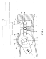
- FIG. 1 to FIG. 7 is a cam device as applied to an APC device 1 .
- An input shaft 4 is provided in a horizontal direction in a chassis-shaped housing 3 having integrated leg portions 2.
- An output shaft 5 is provided adjacent to and in a vertical direction intersecting with the input shaft 4, and performs rotation operations and lifting operations.
- the input shaft 4 is rotatably supported on both sides in the housing 3 by bearing members 6 and is continuously driven to rotate in one direction by a rotation drive source that is not shown in the drawings.
- a roller gear cam 7 is provided as a rotation converting cam that produces, from the continuous one-way rotation of the input shaft 4, an intermittent rotation movement in which rotation and halt are repeated.
- the roller gear cam 7 engages with rotation transmitting cam followers 9 of a turret 8, which are described later, provided at the output shaft 5 so as to be readily engaged/disengaged, and outputs the intermittent rotation movement, which is generated in accordance with the cam profile, to the turret 8 via the rotation transmitting cam followers 9.
- a pair of plate cams 10 is provided on both sides of the roller gear cam 7 as lift generating cams, and these produce a lifting movement from the one-way continuous rotation of the input shaft 4.
- the plate cams 10 have the same cam profile and are provided at the same phase around the input shaft 4.
- the plate cams 10 are formed integrally with the roller gear cam 7 by being manufactured in the side surfaces of the roller gear cam 7. According to requirements, it is also possible to attach the plate cams 10 to the input shaft 4 as components separate from the roller gear cam 7.
- the plate cams 10 are engaged with oscillating arm cam followers 13 that are provided at a central portion of oscillating arms 12, which are lifting means each being supported at one end by a support pin 11 on the inner wall of the housing 3, and the other end of the oscillating arms 12 is caused to move reciprocally in the vertical direction in accordance with the cam profile of the plate cams 10, which generate lifting movements.
- oscillating arm cam followers 13 that are provided at a central portion of oscillating arms 12, which are lifting means each being supported at one end by a support pin 11 on the inner wall of the housing 3, and the other end of the oscillating arms 12 is caused to move reciprocally in the vertical direction in accordance with the cam profile of the plate cams 10, which generate lifting movements.
- the output shaft 5 is formed as a hollow cylindrical member, and is arranged inserted over a solid columnar guide member 14 that is arranged protruding from a base portion of the housing 3.
- the output shaft 5 is supported so as to be rotatable and vertically slidable in its entirety with respect to the housing 3 via the guide member 14, and the guide member 14 guides the rotation operations and lifting operations of the output shaft.
- a pallet 15 on which a workpiece W is placed is attached to a protruding end of the output shaft 5, which extends outwards from the housing 3.
- annular engagement groove 16 is formed along the rotation direction of the output shaft 5, and lift cam followers 17 each provided at the other end of the oscillating arms 12 are sandwiched between the upper wall and lower wall of the annular engagement groove 16 and are slidably engaged thereto.
- the lift cam followers 17 slide in the annular engagement groove 16 so as not to interfere with the rotation operation of the output shaft 5, they are engaged in the vertical direction with respect to the annular engagement groove 16 so as to input, to the output shaft 5, the lifting movement that is output by the plate cams 10.
- the pair of oscillating arms 12 on both sides of the roller gear cam 7 is arranged such that the arms sandwich the output shaft 5 horizontally therebetween from the left and right sides along its diameter direction in order to input approximately equal lifting power to the output shaft 5 from both sides thereof so as to subject the output shaft 5 to lifting movements stably in the directly-vertical direction without causing it to tilt.
- the output shaft 5 is provided with a turret 8 that is positioned below the annular engagement groove 16 and that has rotation transmitting cam followers 9 which are engaged with the roller gear cam 7.
- the rotation transmitting cam followers 9 are arranged at equal intervals in the circumferential direction of the turret 8. In this way, the turret 8 is configured so that the intermittent rotation movements that are output by the roller gear cam 7 are input to the output shaft 5.
- the turret 8 in particular, is formed integrally with the output shaft 5 as a portion of the output shaft 5 itself, without any kind of junction with respect to the output shaft 5, and consequently, the output shaft 5 and the turret 8 become a functional portion that is fabricated as a single component, and are formed such that they are coupled together through the high rigidity of the material of that component.
- the input shaft 4 is arranged inserted through the oscillating arms 12, and in each of the oscillating arms 12, which oscillate about the support pins 11, a long hole 18 is formed along the locus of the oscillation operations of each arm at a position where the input shaft 4 is inserted, such that the arms do not interfere with the input shaft 4 when they are oscillating.
- a sealing member 19 is arranged in the housing 3 to seal the portion through which the output shaft 5 passes.
- FIG. 6 and FIG. 7 show line charts of the timing of an intermittent rotation movement and a lifting movement respectively output by the roller gear cam 7 and the plate cams 10 that are rotated by the input shaft 4, which is rotationally driven continuously in one direction, and also show corresponding operation states of the APC device 1.
- the roller gear cam 7 is in a dwell period in which no rotation displacement is output even when the input shaft 4 is rotating, and the rotation of the turret 8 is in a halted state. Then, when the ascending lifting operation of the output shaft 5 is completed and the output shaft 5 enters a halted state, the output shaft 5 carries out a rotation operation for 180° ((b)-(c)), while being guided with the guide member 14, that is caused by the roller gear cam 7 via the turret 8.
- the pallet 15 attached to the output shaft 5 continuously carries out an operation that is completed with two revolutions of the input shaft wherein, for the first revolution of the input shaft 4, the pallet is raised, rotated for 180°, and lowered, and then for the second revolution, it is raised again, rotated for 180° in the same direction, and lowered.
- the input shaft 4, which causes the output shaft 5 to lift and rotate continuously rotates at a constant velocity without slowing down or pausing.
- the turret 8, which is formed integrally with the output shaft 5, is lifted upwards and downwards together with the output shaft 5. That is, when the output shaft 5 completes an ascending lift during the dwell period of the roller gear cam 7 (at this time the cam profile of the roller gear cam 7 is straight in the vertical direction so that there is no displacement of the rotation transmitting cam followers 9 engaged with this cam) in accordance with the cam profiles of the roller gear cam 7 and the plate cams 10, the rotation transmitting cam followers 9 engage with the roller gear cam 7, after which the rotation movement of the roller gear cam 7 is input to the turret 8, and when the output shaft 5 subsequently performs a descending lift during the dwell period of the roller gear cam 7, the rotation transmitting cam followers 9 are released from the roller gear cam 7.
- the extent of the release of the rotation transmitting cam followers 9 from the roller gear cam 7 can be adjusted in relation to the lift amount, and it is possible to set the meshing of these components so that they do not completely disengage, or to set them so that they do completely disengage.
- a detent or the like is provided to impede the rotation of the turret 8 or the output shaft 5 in order to ensure restoration of engagement of the meshing.
- the turret 8 is formed integrally with the output shaft 5, it is possible to ensure considerable rigidity without enlarging these components to which the lifting movements and rotation movements are input. It is also possible to input high rotation torque to the turret 8 while ensuring lifting operations and rotation operations that compare favorably with conventional operations with respect to the output shaft 5, and it is also possible to handle heavy items appropriately while maintaining a compact device configuration.
- roller gear cam 7 and the plate cams 10 are provided on the single input shaft 4 and it is possible to achieve output for both lifting operations and rotation operations from the rotation of the input shaft 4, these operations can be completely synchronized, thus enabling higher speeds in the device operation.
- the output shaft 5 is formed as a hollow cylindrical member that is provided in one piece with the turret 8 and its rotation operations and lifting operations are guided by the guide member 14 inserted in the output shaft 5, the guide member 14 is able to support the load applied to the output shaft 5, which handles heavy items, and suitably guide the movements therein, thus enabling the stability of movement of the output shaft 5 to be improved.
- the oscillating arms 12, which input a lifting movement to the output shaft 5 are provided as a pair and positioned flanking the output shaft 5 on both sides, the oscillating arms 12 are able to share the load of heavy items and ensure a stable, directly-vertical lifting movement without tilting the output shaft 5. It is possible to improve the stability of movement of the output shaft 5 also from this perspective.
- cam device according to the present invention was described using an example of a cam device according to the present invention being applied to the APC device 1, but there is no limitation to this, and naturally, the invention may also be applied to various large-scale mechanical devices that output both lifting operations and rotation operations to handle heavy items.
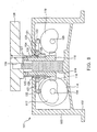
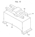
- FIG. 8 to FIG. 13 is a cam device as applied to an APC device 101.
- a primary input shaft 104 and a secondary input shaft 105 are provided side by side parallel to each other in a horizontal direction with an interval therebetween in a chassis-shaped housing 103 having integrated leg portions 102.
- An output shaft 106 is provided between the primary input shaft 104 and the secondary input shaft 105 and in a vertical direction intersecting with the input shafts, and performs rotation operations and lifting operations.
- the primary input shaft 104 is rotatably supported on both sides in the housing 103 by bearing members 107 and is continuously driven to rotate in one direction by a rotation drive source that is not shown in the drawings.
- the secondary input shaft 105 is formed with the same diameter as the primary input shaft 104 and is rotatably supported on both sides in the housing 103 by bearing members 108.
- a rotation transmitting means 109 is provided between the primary input shaft 104 and the secondary input shaft 105 such that the rotation of the primary input shaft 104 is transmitted to the secondary input shaft 105 to synchronize the rotation of the secondary input shaft 105 with the primary input shaft 104, that is, so that continuous one-way rotation with at least the same number of times of revolutions is achieved.
- the rotation transmitting means 109 is made of: a drive gear 110 that is provided at the primary input shaft 104 and that rotates unitarily therewith; a first idle gear 111 that is rotatably supported in the housing 103 and that meshes with the drive gear 110; a second idle gear 112 that is rotatably supported in the housing 103 and that meshes with the first idle gear 111; and a driven gear 113 that is provided at the secondary input shaft 105 and that meshes with the second idle gear 112 to rotationally drive the secondary input shaft 105 .
- a roller gear cam 114 is provided as a rotation converting cam that produces, from the continuous one-way rotation of the primary input shaft 104, an intermittent rotation movement in which rotation and halt are repeated.
- the roller gear cam 114 engages with rotation transmitting cam followers 116 of a turret 115, which are described later, provided at the output shaft 106 so as to be readily engaged/disengaged, and outputs the intermittent rotation movement, which is generated in accordance with the cam profile, to the turret 115 via the rotation transmitting cam followers 116.
- At the primary input shaft 104 at least two plate cams 117 are provided, as primary shaft-side lift generating cams, on the sides of the roller gear cam 114, respectively one on each side, and these produce a lifting movement from the one-way continuous rotation of the primary input shaft 104.
- the plate cams 117 have the same cam profile and are provided at the same phase around the primary input shaft 104.
- the plate cams 117 are formed integrally with the roller gear cam 114 by being manufactured on the side surfaces of the roller gear cam 114. According to requirements, it is also possible to attach the plate cams 117 to the primary input shaft 104 as components separate from the roller gear cam 114.
- At the secondary input shaft 105 at least two plate cams 118 are also provided, as secondary shaft-side lift generating cams, arranged respectively in opposition to the plate cams 117 of the primary input shaft side, and these produce a lifting movement from the one-way continuous rotation of the secondary input shaft 105 .
- the secondary input shaft 105 rotates in reverse to the primary input shaft 104, and therefore, the plate cams 118 have a cam profile that is the inverted profile of the plate cams 117 of the primary input shaft side and are provided at the same phase around the secondary input shaft 105, so that in the period of one revolution of the primary input shaft 104 and the secondary input shaft 105, all the plate cams 117 and 118 produce an equivalent lifting movement.
- all the plate cams 117 and 118 are provided with the same cam profile and at the same phase. Further, needless to say, even when the primary input shaft 104 and the secondary input shaft 105 have different diameters, it is possible to let all the plate cams 117 and 118 produce an equivalent lifting movement by appropriately setting the cam profile of each of the plate cams 117 and 118 of the primary input shaft 104 and the secondary input shaft 105.
- the timing of the lifting movement and the rotation movement is completely synchronized by providing both the plate cams 117 of the primary input shaft side and the roller gear cam 114 at the same primary input shaft 104, and by synchronizing the rotation of the secondary input shaft 105 with the primary input shaft 104 as regards the secondary input shaft side plate cams 118.
- the output shaft 106 is formed as a hollow cylindrical member, and is arranged inserted over a solid columnar guide member 119 that is arranged protruding from a base portion of the housing 103.
- the output shaft 106 is supported so as to be rotatable and vertically slidable in its entirety with respect to the housing 103 via the guide member 119, and the guide member 119 guides these rotation operations and lifting operations.
- a lift plate 120 is provided positioned approximately at a central portion in the axial direction of the output shaft 106.
- the lift plate 120 is formed with outer dimensions such that the width between the primary input shaft and the secondary input shaft does not interfere with the roller gear cam 114, and arm portions 121 are integrally formed at the four corners thereon and reach directly above the respective plate cams 117 and 118 .
- Lift cam followers 122 each engaging with each of the plate cams 117 and 118 and producing mutually equivalent lifting movements, are provided at the tip ends of the arm portions 121.
- a ring-shaped member 123 is arranged covering the upper portion of the output shaft 106, and between the lower end of the ring-shaped member 123 and a circular depression 124 of the lift plate 120 formed around the output shaft 106, a thrust bearing 125 is interposed to support the thrust produced between the lift plate 120 and the output shaft 106 during the transmission of a lifting movement and to allow rotation of the output shaft 106 relative to the lift plate 120.
- a pallet 126 on which the workpiece W is mounted is bolted to the ring-shaped member 123 at the upper end of the output shaft 106.
- An upper end 127 of the guide member 119 passes through the ring-shaped member 123 and, in order to stabilize the revolving movement and the lifting movement of the pallet 126, is engaged with an aperture portion 128 formed in the center of revolution of the pallet 12 6, such that it is rotatable and relatively movable in the vertical direction.
- the output shaft 106 is provided with a turret 115 that is arranged under the lift plate 120 and that has rotation transmitting cam followers 116 which are engaged with the roller gear cam 114.
- the rotation transmitting cam followers 116 are arranged at equal intervals in the circumferential direction of the turret 115. In this way, the turret 115 is configured so that the intermittent rotation movements that are output by the roller gear cam 114 are input to the output shaft 106.
- the turret 115 in particular, is formed integrally with the output shaft 106 as a portion of the output shaft 106 itself, without any kind of junction with respect to the output shaft 106, and consequently, the output shaft 106 and the turret 115 become a functional portion that is fabricated as a single component, and are formed such that they are coupled together through the high rigidity of the material of that component. It should be noted that a sealing member 129 is arranged in the housing 103 to seal the portion through which the output shaft 106 passes.
- FIG. 12 and FIG. 13 show line charts of the timing of an intermittent rotation movement and a lifting movement respectively output by the roller gear cam 114 and the plate cams 117 and 118 that are rotationally driven by the primary input shaft 104, which is rotationally driven continuously in one direction, and also show corresponding operation states of the APC device 101.
- the roller gear cam 114 is in a dwell period in which no rotation displacement is output even when the primary input shaft 104 is rotating, and the rotation of the turret 115 is in a halted state.
- the output shaft 106 carries out a rotation operation for 180° ((b)-(c)), while being guided with the guide member 119, that is caused by the roller gear cam 114 via the turret 115. Then, when the rotation operation of the output shaft 106 up to 180° is completed and the roller gear cam 114 enters a dwell period so that the rotation of the turret 115 is brought into a halted state, the output shaft 106 carries out a descending lifting operation ((c)-(d)), while being guided with the guide member 119, that is caused by the plate cams 117 and 118.
- the pallet 126 attached to the output shaft 106 continuously carries out an operation that is completed with two revolutions of the primary input shaft wherein, for the first revolution of the primary input shaft 104, the pallet is raised, rotated for 180°, and lowered, and then for the second revolution, it is raised again, rotated for 180° in the same direction, and lowered.
- the primary input shaft 104 and the secondary input shaft 105 which cause the output shaft 106 to lift and rotate, continuously rotate at a constant velocity without slowing down or pausing.
- the turret 115 which is formed integrally with the output shaft 106, is lifted upwards and downwards together with the output shaft 106. That is, when the output shaft 106 completes an ascending lift during the dwell period of the roller gear cam 114 (at this time the cam profile of the roller gear cam 114 is straight in the vertical direction so that there is no displacement of the rotation transmitting cam followers 116 engaged with this cam) in accordance with the cam profiles of the roller gear cam 114 and the plate cams 117 and 118 , the rotation transmitting cam followers 116 engage with the roller gear cam 114, after which the rotation movement of the roller gear cam 114 is input to the turret 115, and when the output shaft 106 subsequently performs a descending lift during the dwell period of the roller gear cam 114 , the rotation transmitting cam followers 116 are released from the roller gear cam 114.
- the extent of the release of the rotation transmitting cam followers 116 from the roller gear cam 114 can be adjusted in relation to the lift amount, and it is possible to set the meshing of these components so that they do not completely disengage, or to set them so that they do completely disengage.
- a detent or the like is provided to impede the rotation of the turret 115 or the output shaft 106 in order to ensure restoration of engagement of the meshing.
- the output shaft 106 is subjected to a lifting operation by inputting a lifting movement from the lift plate 120 with at least four plate cams 117 and 118 provided at the primary input shaft 104 and the secondary input shaft 105, which rotate in synchronization with each other, it is possible to share the load of heavy items among the plate cams 117 and 118 and ensure a stable, directly-vertical lifting movement without tilting the output shaft 106, and therefore it is possible to improve the stability of movement of the output shaft 106 to which the load of heavy items is applied.
- the turret 115 is formed integrally with the output shaft 106 , it is possible to ensure cons iderable rigidity without enlarging these components to which the lifting movements and rotation movements are input. It is also possible to input high rotation torque to the turret 115 while ensuring lifting operations and rotation operations that compare favorably with conventional operations with respect to the output shaft 106, and it is also possible to handle heavy items appropriately while maintaining a compact device configuration.
- the device is conf igured with the cams 114, 117 , and 118 as main components from which hydraulic devices are eliminated.
- the plate cams 117 and the roller gear cam 114 of the primary input shaft side are provided at the same primary input shaft 104, and the rotation of the secondary input shaft 105 is synchronized with the primary input shaft 104 as regards the plate cams 118 of the secondary input shaft side. Therefore, the timing of the lifting movements and rotation movements of these can be completely synchronized, thus enabling higher speeds in the device operation.
- the output shaft 106 is formed as a hollow cylindrical member that is provided in one piece with the turret 115 and its rotation operations and lifting operations are guided by the guide member 119 inserted in the output shaft 106, the guide member 119 is able to support the load applied to the output shaft 106, which handles heavy items, and suitably guide the movements therein, thus enabling the stability of movement of the output shaft 106 to be improved. Further, it is possible to improve stability in revolution and lifting movements of the pallet 126, since the guide member 119 arranged in the housing 103 is configured to be engaged with the pallet 126.
- the foregoing embodiment was described using the plate cams 117 and 118 as illustrative examples of lift generating cams, but instead of these, it is also possible to use groove cams. Furthermore, the foregoing embodiment was described using an example of a cam device according to the present invention being applied to the APC device 101, but there is no limitation to this, and naturally, the invention may also be applied to various large-scale mechanical devices that output both lifting operations and rotation operations to handle heavy items.
- cam device With a cam device according to the present invention, it is possible to ensure higher ecological standards by adopting a device configuration that uses cams as a main component, to enable the transmission of high rotation torque while making the device compact by forming a turret integrally with the output shaft, to achieve high-speed operation by being able to output lifting movements and rotation movements with the rotation of a single input shaft, and to be suitably applied as a base machine for various types of mechanical equipments such as APC devices for handling heavy items.
- the movements of the output shaft that handles heavy items can be suitably guided by a guide member, thus enabling the stability of those movements to be improved.
- a cam device it is possible to ensure higher ecological standards by adopting a device configuration that uses cams as a main component, to enable the transmission of high rotation torque while making the device compact by forming a turret integrally with the output shaft, and to achieve high-speed operation by being able to output lifting movements and rotation movements from the rotation of a primary input shaft.
- the movements of the output shaft that handles heavy items can be suitably guided by a guide member, thus enabling the stability of those movements to be improved.
Landscapes
- Engineering & Computer Science (AREA)
- Mechanical Engineering (AREA)
- General Engineering & Computer Science (AREA)
- Transmission Devices (AREA)
Claims (3)
- Nockenvorrichtung, mit
einer Ausgangswelle (5; 106) zum Ausführen eines Drehvorgangs und eines Hubvorgangs durch Empfangen einer Drehbewegung und einer Hubbewegung, die von einem brehumsctzungsnocken (7) bzw. einem Huberzeugungsnocken (10) ausgegeben werden, die an einer Eingangswelle (4; 104) vorgesehen sind, die rotatorisch angetrieben wird, und
einem Revolverkopf (8; 115), um in die Ausgangswelle (5; 106) die Drehbewegung einzugeben, die von dem Drehumsetzungsnocken (7) ausgegeben wird,
wobei die Ausgangswelle (5; 106), die den Revolverkopf (8; 115) enthält, den Drehvorgang und den Hubvorgang ausführt, währen sie durch ein Führungselement (14) geführt wird;
dadurch gekennzeichnet, dass:der Revolverkopf (8; 115) einteilig mit der Ausgangswelle (5; 106) ausgebildet ist unddie Ausgangswelle (5; 106), die den Revolverkopf (8; 115) aufweist, als ein hohles zylindrisches Element ausgebildet ist und das Führungselement (14) zum Führen des Drehvorgangs und des Hubvorgangs der Ausgangswelle (5; 106) in die Ausgangswelle (5; 106) eingesetzt ist. - Nockenvorrichtung nach Anspruch 1,
wobei entsprechend dem Huberzeugungsnocken (10) ein Paar Hubarme (12) vorgesehen ist, um in die Ausgangswelle (5) die von dem Huberzeugumgsnocken (10) ausgegebene Hubbewegung einzugeben, und
wobei jeder der Hubarme ein Loch besitzt, durch das die Eingangswelle (4) eingesetzt ist, so dass sich der Hubarm und die Eingangswelle nicht stören. - Nockenvorrichtung nach Anspruch 1, ferner mit:einer sekundären Eingangswelle (105), die neben der Eingangswelle (104) angeordnet ist und sich synchron mit der Eingangswelle dreht, indem sie die Übertragung der Drehung der Eingangswelle über ein Drehübertragungsmittel (109) empfängt;wenigstens zwei primären wellenseitigen Huberzeugungsnocken (117), die an der Eingangswelle angeordnet sind;wenigstens zwei sekundären wellenseitigen Huherzeugungsnocken (118), die an der sekundären Eingangswelle angeordnet sind; undeiner Hubplatte (120), die durch Empfangen einer Hubbewegung, die von den wenigstens vier sekundären wellenseitigen Huberzeuglungsnocken und primären wellenseitigen Huberzeugungsnocken ausgegeben wird, angehoben wird; undwobei die Ausgangswelle den Hubvorgang durch Empfangen der Hubbewegung von der Hubplatte ausführt.
Applications Claiming Priority (1)
| Application Number | Priority Date | Filing Date | Title |
|---|---|---|---|
| PCT/JP2002/011003 WO2004038255A1 (ja) | 2002-10-23 | 2002-10-23 | カム装置 |
Publications (3)
| Publication Number | Publication Date |
|---|---|
| EP1555457A1 EP1555457A1 (de) | 2005-07-20 |
| EP1555457A4 EP1555457A4 (de) | 2008-09-24 |
| EP1555457B1 true EP1555457B1 (de) | 2010-09-01 |
Family
ID=32170774
Family Applications (1)
| Application Number | Title | Priority Date | Filing Date |
|---|---|---|---|
| EP02777931A Expired - Lifetime EP1555457B1 (de) | 2002-10-23 | 2002-10-23 | Nockenvorrichtung |
Country Status (5)
| Country | Link |
|---|---|
| US (1) | US20050061091A1 (de) |
| EP (1) | EP1555457B1 (de) |
| KR (1) | KR100552305B1 (de) |
| DE (1) | DE60237550D1 (de) |
| WO (1) | WO2004038255A1 (de) |
Families Citing this family (9)
| Publication number | Priority date | Publication date | Assignee | Title |
|---|---|---|---|---|
| EP3069434B1 (de) * | 2013-11-12 | 2019-10-02 | Fraen Mechatronics, LLC | Dualnocken-drehmomentübertragung mechanismus |
| CN106286737A (zh) * | 2015-05-11 | 2017-01-04 | 孙健 | 一种双向凸轮机构 |
| KR101689199B1 (ko) * | 2016-05-17 | 2016-12-23 | (재)대구기계부품연구원 | 캠구동 박스를 적용한 팔레트 교환 장치 |
| CZ2017439A3 (cs) * | 2017-08-01 | 2018-10-03 | VĂšTS, a.s. | Vačkový manipulátor, zejména pro automatickou výměnu nástrojů na obráběcím stroji |
| CN107932169B (zh) * | 2017-12-22 | 2024-08-02 | 苏州苏铸智能装备有限公司 | 一种铸件送料转台 |
| CN110977505A (zh) * | 2019-12-20 | 2020-04-10 | 苏州古田自动化科技有限公司 | 卧式凸轮交换台用升降旋转装置 |
| CN111451800A (zh) * | 2020-04-17 | 2020-07-28 | 遵义市文杰机电有限责任公司 | 一种用于紧固件铣平面的装置 |
| KR102763252B1 (ko) | 2020-09-24 | 2025-02-07 | 삼성전자주식회사 | 힌지 구조물 및 이를 포함하는 전자 장치 |
| DE102021204282A1 (de) | 2021-04-29 | 2022-11-03 | Robert Bosch Gesellschaft mit beschränkter Haftung | Elektrisch angetriebene Weiche für einen Doppelgurtförderer |
Family Cites Families (13)
| Publication number | Priority date | Publication date | Assignee | Title |
|---|---|---|---|---|
| US1718639A (en) * | 1926-08-17 | 1929-06-25 | Droll Joseph William | Mattress-roll forming and stitching machine |
| US2327387A (en) * | 1942-02-19 | 1943-08-24 | United Shoe Machinery Corp | Shoe sewing machine |
| US3552786A (en) * | 1969-05-12 | 1971-01-05 | Rainer K Schmid | Mechanical joint assembly |
| US3869924A (en) * | 1974-02-11 | 1975-03-11 | Stelron Cam Company | Device for transmitting accurate translational and rotary movements |
| US4036374A (en) * | 1975-11-04 | 1977-07-19 | Amc Industries, Inc. | Multi-motion parts handler |
| DE3318398A1 (de) * | 1983-05-20 | 1984-11-22 | Expert Maschinenbau Gmbh, 6143 Lorsch | Handhabungsvorrichtung |
| JPH0752444Y2 (ja) * | 1987-02-03 | 1995-11-29 | 株式会社三共製作所 | カム装置 |
| JPH0259246A (ja) * | 1988-08-23 | 1990-02-28 | Mori Seiki Seisakusho:Kk | 工作機械の自動パレット交換装置 |
| JPH06249316A (ja) * | 1993-02-24 | 1994-09-06 | Ookubo Haguruma Kogyo Kk | 出力軸駆動装置 |
| US5386743A (en) * | 1993-07-13 | 1995-02-07 | Industrial Technology Research Institute | Turret indexing device |
| US5735128A (en) * | 1996-10-11 | 1998-04-07 | Helix Technology Corporation | Cryogenic refrigerator drive |
| JP3669793B2 (ja) * | 1996-11-11 | 2005-07-13 | 株式会社三共製作所 | 自動工具交換装置 |
| US6279219B1 (en) * | 1998-09-24 | 2001-08-28 | Takahiro Engineering Works Ltd. | Roller turret including rollers mounted on support portions of roller shafts, which are eccentric with respect to stud portions fixed in holes in turret body, and method of manufacturing the roller turret |
-
2002
- 2002-10-23 EP EP02777931A patent/EP1555457B1/de not_active Expired - Lifetime
- 2002-10-23 KR KR1020047006291A patent/KR100552305B1/ko not_active Expired - Lifetime
- 2002-10-23 WO PCT/JP2002/011003 patent/WO2004038255A1/ja not_active Ceased
- 2002-10-23 US US10/493,418 patent/US20050061091A1/en not_active Abandoned
- 2002-10-23 DE DE60237550T patent/DE60237550D1/de not_active Expired - Lifetime
Also Published As
| Publication number | Publication date |
|---|---|
| KR100552305B1 (ko) | 2006-02-21 |
| WO2004038255A1 (ja) | 2004-05-06 |
| EP1555457A4 (de) | 2008-09-24 |
| US20050061091A1 (en) | 2005-03-24 |
| DE60237550D1 (de) | 2010-10-14 |
| KR20040068128A (ko) | 2004-07-30 |
| EP1555457A1 (de) | 2005-07-20 |
Similar Documents
| Publication | Publication Date | Title |
|---|---|---|
| EP1555457A1 (de) | Nockenvorrichtung | |
| CN203611246U (zh) | 一种工业机器人 | |
| CN104385260B (zh) | 一种四自由度平面关节机器人结构 | |
| KR100938019B1 (ko) | 공작 기계용 부착부 | |
| KR101110876B1 (ko) | 산업용 로봇 | |
| KR102214851B1 (ko) | 펀칭 장치 | |
| US5876316A (en) | Automatic tool changer | |
| CN113714720A (zh) | 一种机械零部件焊接用多维度智能工装夹具 | |
| KR20090124219A (ko) | 3축 방향 동작형 갠트리 시스템 | |
| JP4695779B2 (ja) | カム装置 | |
| CN102152156A (zh) | 实现一个输入转换成两种输出的变速箱 | |
| JP4598993B2 (ja) | カム装置 | |
| CN115157174A (zh) | 一种行星减速机自动装配工装 | |
| CN110657223A (zh) | 变速行走齿轮箱及行走减速机 | |
| KR100473555B1 (ko) | 더블 피니언을 이용한 고정도 테이블 장치 | |
| CN211398498U (zh) | 变速行走齿轮箱及行走减速机 | |
| CN110775857B (zh) | 一种机械千斤顶 | |
| CN223622182U (zh) | 一种传动齿轮的拨叉装置 | |
| CN221853349U (zh) | 一种间歇式驱动结构及送料装置 | |
| JP3514732B2 (ja) | 回転駆動装置 | |
| JP2001349394A (ja) | 速比切替式遊星歯車装置及びプレス機械用速比切替式遊星歯車装置 | |
| TW565662B (en) | Cam device | |
| KR101541859B1 (ko) | 백래시조절형 건드릴 머신용 테이블장치 | |
| CN220372257U (zh) | 一种电机定转子加工用开孔设备 | |
| EP3677366A1 (de) | Revolverkopfwerkzeugstange |
Legal Events
| Date | Code | Title | Description |
|---|---|---|---|
| PUAI | Public reference made under article 153(3) epc to a published international application that has entered the european phase |
Free format text: ORIGINAL CODE: 0009012 |
|
| 17P | Request for examination filed |
Effective date: 20040506 |
|
| AK | Designated contracting states |
Kind code of ref document: A1 Designated state(s): DE FR GB IT |
|
| A4 | Supplementary search report drawn up and despatched |
Effective date: 20080825 |
|
| 17Q | First examination report despatched |
Effective date: 20081230 |
|
| GRAP | Despatch of communication of intention to grant a patent |
Free format text: ORIGINAL CODE: EPIDOSNIGR1 |
|
| GRAS | Grant fee paid |
Free format text: ORIGINAL CODE: EPIDOSNIGR3 |
|
| GRAA | (expected) grant |
Free format text: ORIGINAL CODE: 0009210 |
|
| AK | Designated contracting states |
Kind code of ref document: B1 Designated state(s): DE FR GB IT |
|
| REG | Reference to a national code |
Ref country code: GB Ref legal event code: FG4D |
|
| REF | Corresponds to: |
Ref document number: 60237550 Country of ref document: DE Date of ref document: 20101014 Kind code of ref document: P |
|
| PGFP | Annual fee paid to national office [announced via postgrant information from national office to epo] |
Ref country code: FR Payment date: 20101020 Year of fee payment: 9 |
|
| PGFP | Annual fee paid to national office [announced via postgrant information from national office to epo] |
Ref country code: DE Payment date: 20101020 Year of fee payment: 9 |
|
| PGFP | Annual fee paid to national office [announced via postgrant information from national office to epo] |
Ref country code: IT Payment date: 20101015 Year of fee payment: 9 Ref country code: GB Payment date: 20101020 Year of fee payment: 9 |
|
| PLBE | No opposition filed within time limit |
Free format text: ORIGINAL CODE: 0009261 |
|
| STAA | Information on the status of an ep patent application or granted ep patent |
Free format text: STATUS: NO OPPOSITION FILED WITHIN TIME LIMIT |
|
| 26N | No opposition filed |
Effective date: 20110606 |
|
| REG | Reference to a national code |
Ref country code: DE Ref legal event code: R097 Ref document number: 60237550 Country of ref document: DE Effective date: 20110606 |
|
| GBPC | Gb: european patent ceased through non-payment of renewal fee |
Effective date: 20111023 |
|
| REG | Reference to a national code |
Ref country code: FR Ref legal event code: ST Effective date: 20120629 |
|
| PG25 | Lapsed in a contracting state [announced via postgrant information from national office to epo] |
Ref country code: DE Free format text: LAPSE BECAUSE OF NON-PAYMENT OF DUE FEES Effective date: 20120501 |
|
| REG | Reference to a national code |
Ref country code: DE Ref legal event code: R119 Ref document number: 60237550 Country of ref document: DE Effective date: 20120501 |
|
| PG25 | Lapsed in a contracting state [announced via postgrant information from national office to epo] |
Ref country code: FR Free format text: LAPSE BECAUSE OF NON-PAYMENT OF DUE FEES Effective date: 20111102 Ref country code: GB Free format text: LAPSE BECAUSE OF NON-PAYMENT OF DUE FEES Effective date: 20111023 Ref country code: IT Free format text: LAPSE BECAUSE OF NON-PAYMENT OF DUE FEES Effective date: 20111023 |