EP1555203A1 - Optisches Einrichtung für den Einsatz unter stark wechselndem Umgebungsdruck - Google Patents
Optisches Einrichtung für den Einsatz unter stark wechselndem Umgebungsdruck Download PDFInfo
- Publication number
- EP1555203A1 EP1555203A1 EP05000098A EP05000098A EP1555203A1 EP 1555203 A1 EP1555203 A1 EP 1555203A1 EP 05000098 A EP05000098 A EP 05000098A EP 05000098 A EP05000098 A EP 05000098A EP 1555203 A1 EP1555203 A1 EP 1555203A1
- Authority
- EP
- European Patent Office
- Prior art keywords
- housing
- functional position
- protective device
- pressure level
- optical device
- Prior art date
- Legal status (The legal status is an assumption and is not a legal conclusion. Google has not performed a legal analysis and makes no representation as to the accuracy of the status listed.)
- Granted
Links
- 230000007613 environmental effect Effects 0.000 title 1
- 230000003287 optical effect Effects 0.000 claims abstract description 50
- 230000001681 protective effect Effects 0.000 claims abstract description 38
- 238000007789 sealing Methods 0.000 claims abstract description 32
- 238000000034 method Methods 0.000 description 7
- XLYOFNOQVPJJNP-UHFFFAOYSA-N water Substances O XLYOFNOQVPJJNP-UHFFFAOYSA-N 0.000 description 5
- 238000010521 absorption reaction Methods 0.000 description 3
- 230000004075 alteration Effects 0.000 description 3
- 230000001419 dependent effect Effects 0.000 description 3
- 238000010276 construction Methods 0.000 description 2
- 230000009189 diving Effects 0.000 description 2
- 230000000694 effects Effects 0.000 description 2
- 239000000463 material Substances 0.000 description 2
- 230000007246 mechanism Effects 0.000 description 2
- 230000008569 process Effects 0.000 description 2
- 230000008859 change Effects 0.000 description 1
- 230000009194 climbing Effects 0.000 description 1
- 230000002349 favourable effect Effects 0.000 description 1
- 238000004519 manufacturing process Methods 0.000 description 1
- 230000000717 retained effect Effects 0.000 description 1
- 238000000926 separation method Methods 0.000 description 1
Images


Classifications
-
- G—PHYSICS
- G02—OPTICS
- G02B—OPTICAL ELEMENTS, SYSTEMS OR APPARATUS
- G02B23/00—Telescopes, e.g. binoculars; Periscopes; Instruments for viewing the inside of hollow bodies; Viewfinders; Optical aiming or sighting devices
- G02B23/02—Telescopes, e.g. binoculars; Periscopes; Instruments for viewing the inside of hollow bodies; Viewfinders; Optical aiming or sighting devices involving prisms or mirrors
- G02B23/08—Periscopes
-
- B—PERFORMING OPERATIONS; TRANSPORTING
- B63—SHIPS OR OTHER WATERBORNE VESSELS; RELATED EQUIPMENT
- B63G—OFFENSIVE OR DEFENSIVE ARRANGEMENTS ON VESSELS; MINE-LAYING; MINE-SWEEPING; SUBMARINES; AIRCRAFT CARRIERS
- B63G8/00—Underwater vessels, e.g. submarines; Equipment specially adapted therefor
- B63G8/38—Arrangement of visual or electronic watch equipment, e.g. of periscopes, of radar
Definitions
- the present invention relates to an optical device for use under strong changing ambient pressure, in particular for a periscope or an Optronik mast, with a housing; a first area in which a translucent element in the area a recess of the housing is arranged, and a first sealing gap between the light-transmitting element and the housing sealing first sealing means, to seal the interior of the housing from the environment of the housing is formed to a first pressure level.
- the present invention is therefore based on the object, an optical device of the type mentioned above to provide which the above-mentioned disadvantages not or at least to a lesser extent, and in particular at reduced levels Effort allows improved optical performance of the overall system.
- the present invention solves this problem starting from an optical device according to the preamble of claim 1 by the in the characterizing part of claim 1 specified characteristics.
- the present invention is based on the technical teaching that an improved achieve optical performance of the overall system with a total of reduced effort can, if one of a first functional position in a second functional position movable Guard is provided, which is arranged outside the housing.
- the protective device In its first functional position, covers the first region in such a sealing manner relative to the environment of the housing, that at an ambient pressure above the first pressure level in a space between the protective device and the first range prevails at most the first pressure level.
- the protective device releases the translucent element.
- both the light-transmitting element as well as the first sealing device only for a comparatively low first pressure level must be designed as they are protected by the protective device from higher ambient pressures are protected.
- the translucent element for example, a flat or curved disc or a lens, can then be made correspondingly thin.
- the material and manufacturing costs decrease the translucent Element.
- this increases the optical performance of the overall system, because it due to the smaller thickness of the translucent element to lower absorption losses and aberrations comes.
- the optical device according to the invention can be anywhere in an advantageous manner insert, where the incidence of light through the translucent element into the housing interior is required only at relatively low ambient pressures. This is for example with periscopes or Optronik masts for submarines the case. Their optical functions, For example, looking through, are usually required only when the end located above the water level. At dive trip with retracted Sehrohr or Optronikmast the optical function is not needed, so that the translucent Element without disadvantages can be covered by the protective device.
- the first pressure level can basically be any pressure level act.
- the optical device according to the invention is preferred for operation up to formed a permissible maximum pressure level.
- the first pressure level is then preferably below 30% of this maximum allowable pressure level.
- Preferably the first pressure level is below 20% of the maximum allowable pressure level. Further preferably, it is below 10% of the maximum allowable pressure level.
- the first pressure level is preferably below 3 bar. Further preferably below 2 bar. This can be particularly advantageous simple configurations of the translucent element and the first sealing device.
- the above information is based on a normal pressure in the interior of the housing about 1 bar out. It is understood that for the design of the translucent element and the first sealing means the differential pressure between the housing interior and the environment of the housing is relevant. At elevated pressures in the housing interior Accordingly, the first pressure level can be correspondingly higher.
- the protective device is preferably in its first functional position so sealing on Housing indicates that the pressure in the space between it and the first area of the Housing with the translucent element at any ambient pressures the first Pressure level does not exceed.
- a seal is achieved which independently from the ambient pressure an approximately constant pressure level in this Gap ensures the mechanical loads, in particular the alternating loads, of the translucent member and the first sealing means.
- the protective device can basically be designed arbitrarily to the protection function in to fulfill their first functional position.
- basically any Movements for the movement between the first functional position and the second Functional position be provided.
- the protective device is pivotally mounted on the housing. It can be designed, for example, as a simple cover, which is pivotable on the housing is arranged, that in its first functional position, the translucent element covers.
- the Protective device slidably mounted on the housing. This can be for example to act a simple closable bulkhead or the like, which in a corresponding frame is pushed in front of the translucent element to this in the first functional position to protect against the ambient pressure. This understands it is that the protective device rotatably and / or longitudinally displaceable can be.
- the housing is tubular and the protective device as the housing surrounding tubular jacket is formed. This can then be easier Be moved in the axial direction in its first operating position.
- the seal between the protection device in the first functional position and the housing can in principle be done in any suitable manner.
- the second sealing device can, for example, at the Protective device may be arranged.
- the second sealing means on the housing arranged to keep the moving masses as low as possible.
- the protective device For moving the protective device between its first functional position and its second functional position can basically any suitably designed drive device be provided. This can be, for example, any mechanical, electrical or hydraulic drive means or combinations thereof act.
- the protective device comprises a drive device for moving the protective device between the first and second functional position, the automatic procedure the protective device in the first functional position when exceeding a predetermined first limit value is formed by the ambient pressure of the housing.
- the ambient pressure can be detected by a corresponding sensor or the like and an associated control device are supplied, which then the drive controls accordingly.
- the Protective device a drive device for moving the protective device between the first and second functional position, which is the automatic method of Protection device in the second functional position falls below a predetermined second limit is formed by the ambient pressure of the housing.
- the ambient pressure may be detected by a corresponding sensor or the like and an associated control device, which then drives controls accordingly.
- the light-transmitting element be designed or optimized for any wavelengths.
- the translucent element may be at least for use in the infrared range, in particular in the range of wavelengths of 1 .mu.m to 15 .mu.m, formed be. In particular, it can be used in the range of wavelengths of 3 microns to 5 microns and / or in the range of wavelengths of 8 microns to 12 microns be.
- the present invention further relates to a periscope or Optronikmast, in particular for an underwater vehicle, which or an optical according to the invention Device has.
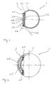
- FIG. 1 shows a schematic sectional view of a preferred embodiment of the invention Periscope 1 according to the invention for a submarine with a preferred embodiment the optical device 2 according to the invention, at the free end of the periscope. 1 is arranged.
- the optical device 1 comprises a housing 2.1 with a first region 2.2, in which a window-like recess 2.3 is arranged.
- a window-like recess 2.3 is arranged in this recess 2.3.
- a translucent Element inserted in the form of a transparent disc 2.4.
- Disk 2.4 can drop light into the interior of the housing 2.1.
- the interior of the housing Closes to the disc 2.4 the - not shown in Figure 1 - further optical System of the periscope 1 on. This optical system must be protected against ingress of moisture become.
- a first sealing gap between the disk 2.4 and the housing 2.1 is therefore through a first sealing device sealed in the form of a first seal 2.5.
- the first seal becomes the interior of the housing 2.1 opposite to the first seal Environment of the housing 2.1 sealed, in which a certain ambient pressure prevails.
- the periscope 1 is for operation up to a maximum allowable pressure level of 40 formed bar.
- the disc 2.4 and the first seal are for a first pressure level the ambient pressure of 2 bar designed.
- the first pressure level is therefore 5% the permissible maximum pressure level. Thanks to this interpretation to a comparatively low pressure level, both the disc 2.4 and the first seal 2.5 are comparatively simply designed.
- the disk 2.4 has a relatively small thickness on. This has an advantageous effect on the overall optical performance of the system since thanks to the small thickness of the disc 2.4 only comparatively low absorption losses and aberrations occur.
- a protective device in the form of an axis 2.6 pivotable lid 2.7 provided.
- the lid 2.7 is by a - not shown - drive between its illustrated first functional position and its moved by the dashed contour 2.8 indicated second functional position. In In its first functional position, the cover 2.7 covers the disc 2.4, while he the Disc 2.4 releases in its second functional position.
- the cover 2.7 In its first functional position, the cover 2.7 covers the first area 2.2 of the housing 2.1 with the disc 2.4 against the environment sealing off. For this he lies at one second sealing means in the form of a second seal 2.9, which on the outside of the housing 2.1 is arranged.
- the lid 2.7, its drive and its lock and the seal 2.9 are designed so that regardless of the environment of the housing 2.1 prevailing the ambient pressure in the space 2.10 between the Cover 2.7 and the first area 2.2 of the housing 2.1 at most one pressure on the above first pressure level prevails. In other words, there is this gap 2.10 maximum pressure of about 2 bar. It is understood in particular that these components can be designed so that in the space 2.10 independently from the prevailing in the vicinity of the housing 2.1 of the ambient pressure substantially no pressure change.
- the cover 2.7 and the associated drive mechanism are designed so that the Lid 2.7 in case of failure of its drive mechanism automatically in its first functional position moved, in any case, damage to the optical system during diving to avoid.
- the lid can at least partially from correspondingly translucent material consist.
- FIG. 2 shows a schematic sectional illustration of a further preferred embodiment a periscope 1 'according to the invention for a submarine with another preferred embodiment of the optical device 2 'according to the invention, the free end of the periscope 1 'is arranged.
- This design is similar in its basic Functioning and interpretation of those of Figure 1, so here only on the differences to be received.
- the protective device acts as a sliding bulkhead 2.7 ' is formed, which is mounted in the housing 2.1 'and in the direction of the double arrow 3' between the illustrated first functional position, in which it covers the disc 2.4 ', and the - not shown - second functional position can be moved, in which it the disc 2.4 'releases.
- the second seal 2.9 ' is a Hollow chamber seal, which can be pressurized from the inside to the Ensure sealing effect.
- FIG. 3 shows a schematic sectional illustration of a further preferred embodiment an Optronikmasts 1 "according to the invention for a submarine with another preferred embodiment of the optical device 2 ", the is arranged at the free end of Optronikmasts 1 "
- This version is similar in their basic mode of operation and design likewise those of Figure 1, so that Here too, only the differences should be discussed.
- the protective device is in the form of a tubular jacket a tubular cap 2.7 "is formed, the tubular housing 2.1" in the surrounds first functional position.
- the cap can be moved in the direction of the double arrow 3 "between the illustrated first functional position in which it covers the disc 2.4 ", and the be traversed by the dashed contour 2.11 "indicated second functional position, in which she releases the disk 2.4 ".
- the cap 2.7 is about on the inner circumference of the housing 2.1 extending train-pressure rods 2.12 “by a motor 2.13".
- a pressure sensor 2.14 arranged, which detects the ambient pressure and a corresponding signal to the communicates with it 2.15 "motor 2.13” control connected.
- the controller is 2.15 " adapted to the engine 2.13 “to move the cap 2.7” in its first functional position as soon as the ambient pressure exceeds a first limit.
- the control 2.15 is also designed to run the engine 2.13” to process the cap 2.7 "in its second functional position, as soon as the ambient pressure falls below a second limit.
- the first limit depends on the speed of the expected Pressure rise. Depending on the expected rate of pressure rise and the Procedure of the cap in the first functional position required time it is more or less far below the first pressure level, to ensure that the cap timely in its first functional position, before the ambient pressure is the first Pressure level exceeds.
- the first limit value can in particular be variable. So he can of current state parameters of the submarine, such as the current rate of descent etc., depend. Likewise, it can be varied based on a pressure history forecast, which is created from the values supplied by the pressure sensor 2.14 ".
- the second limit may be a fixed value.
- the second Limit value can also be defined in a similar way as the first limit value. So it can be based on the speed of the expected pressure drop. Depending on the expected pressure drop rate and the procedure of the cap in the second functional position required time, it is more or less far below the first pressure levels to ensure that the cap is timely in its second Function position is when or before the water surface is reached.
- the second limit value can also be variable. So he can of current state parameters of the submarine, such as the current climbing speed, etc., depend. Likewise, it can be varied based on a pressure curve forecast, which from the created by the pressure sensor 2.14 ".
- FIG. 4 shows a schematic sectional illustration of a further preferred embodiment a Optronikmasts invention 1 '' 'for a submarine with a Another preferred embodiment of the optical device 2 '"according to the invention, which is arranged at the free end of Optronikmasts 1 '' '.
- This version is similar in theirs basic operation and interpretation of those of Figure 3, so here too just to discuss the differences.
- the protective device as a tubular sheath 2.7 '' ' is formed, the tubular housing 2.1 '' 'in both the first and the second Surrounds functional position.
- the jacket 2.7 '' ' can in the direction of the double arrow 3' '' between the illustrated first functional position in which it covers the disc 2.4 '' ', and moved by the dashed contour 2.11 '' 'indicated second functional position in which he releases the disc 2.4 '' '.
- the control of the protective device takes place automatically in other words in this variant with the control for extending or retracting the Optronikmasts 1 '' '. These can simply by a corresponding switch to be operated or the like respectively.
- a pressure or dive depth dependent backup circuit be provided that the timely procedure of the mantle 2.7 '' 'between ensures the first and second functional position by the complete Extending the Optronikmasts 1 '' 'only at certain expected pressures in the range 2.4 "'disk is possible, which are below the first pressure level.
- the disc so the translucent element, for use in the field of visible light and in the infrared, in particular in the range of wavelengths of 1 ⁇ m to 10 ⁇ m. It is understood, however, that the translucent element in other variants of the invention also be optimized for other wavelength ranges can.
Landscapes
- Engineering & Computer Science (AREA)
- Physics & Mathematics (AREA)
- Radar, Positioning & Navigation (AREA)
- Mechanical Engineering (AREA)
- Aviation & Aerospace Engineering (AREA)
- Astronomy & Astrophysics (AREA)
- General Physics & Mathematics (AREA)
- Optics & Photonics (AREA)
- Mechanical Coupling Of Light Guides (AREA)
- Telescopes (AREA)
Abstract
Description
- Figur 1
- eine schematische Schnittdarstellung einer bevorzugten Ausführungsform des erfindungsgemäßen Sehrohrs mit einer bevorzugten Ausführungsform der erfindungsgemäßen optischen Einrichtung;
- Figur 2
- eine schematische Schnittdarstellung einer weiteren bevorzugten Ausführungsform eines erfindungsgemäßen Sehrohrs mit einer erfindungsgemäßen optischen Einrichtung;
- Figur 3
- eine schematische Schnittdarstellung einer weiteren bevorzugten Ausführungsform eines erfindungsgemäßen Optronikmasts mit einer erfindungsgemäßen optischen Einrichtung;
- Figur 4
- eine schematische Schnittdarstellung einer weiteren bevorzugten Ausführungsform eines erfindungsgemäßen Optronikmasts mit einer erfindungsgemäßen optischen Einrichtung.
Claims (11)
- Optische Einrichtung für den Einsatz unter stark wechselndem Umgebungsdruck, insbesondere für ein Sehrohr oder einen Optronikmast, mit einem Gehäuse (2.1; 2.1'; 2.1"; 2.1'''), einem ersten Bereich (2.2), in dem ein lichtdurchlässiges Element (2.4; 2.4'; 2.4"; 2.4''') im Bereich einer Ausnehmung (2.3) des Gehäuses (2.1; 2.1'; 2.1 "; 2.1''') angeordnet ist, und einer einen ersten Dichtspalt zwischen dem lichtdurchlässigen Element (2.4; 2.4'; 2.4"; 2.4''') und dem Gehäuse (2.1; 2.1'; 2.1''; 2.1 "') abdichtenden ersten Dichtungseinrichtung (2.5), die zum Abdichten des Innenraumes des Gehäuses (2.1; 2.1'; 2.1''; 2.1''') gegenüber der Umgebung des Gehäuses (2.1; 2.1'; 2.1"; 2.1''') bis zu einem ersten Druckniveau ausgebildet ist, dadurch gekennzeichnet, dass eine von einer ersten Funktionsstellung in eine zweite Funktionsstellung bewegliche Schutzeinrichtung (2.7; 2.7'; 2.7"; 2.7''') vorgesehen ist,die außerhalb des Gehäuses (2.1; 2.1'; 2.1"; 2.1''') angeordnet ist,die in ihrer ersten Funktionsstellung den ersten Bereich (2.2) derart dichtend gegenüber der Umgebung des Gehäuses (2.1; 2.1'; 2.1 "; 2.1''') abdeckt, dass bei einem Umgebungsdruck oberhalb des ersten Druckniveaus in einem Zwischenraum (2.10) zwischen der Schutzeinrichtung (2.7; 2.7'; 2.7"; 2.7''') und dem ersten Bereich (2.2) höchstens das erste Druckniveau vorherrscht, unddie in ihrer zweiten Funktionsstellung das lichtdurchlässige Element (2.4; 2.4'; 2.4"; 2.4''') freigibt.
- Optische Einrichtung nach Anspruch 1, dadurch gekennzeichnet, dass das sie für den Betrieb bis zu einem zulässigen maximalen Druckniveau ausgebildet ist und das erste Druckniveau unterhalb von 30% des zulässigen maximalen Druckniveaus, vorzugsweise unterhalb von 20% des zulässigen maximalen Druckniveaus, weiter vorzugsweise unterhalb von 10% des zulässigen maximalen Druckniveaus, liegt.
- Optische Einrichtung nach Anspruch 1 oder 2, dadurch gekennzeichnet, dass das erste Druckniveau unterhalb von 3 bar, vorzugsweise unterhalb von 2 bar, liegt.
- Optische Einrichtung nach einem der vorhergehenden Ansprüche, dadurch gekennzeichnet, dass die Schutzeinrichtung (2.7) schwenkbar am Gehäuse (2.1) angeordnet ist.
- Optische Einrichtung nach einem der vorhergehenden Ansprüche, dadurch gekennzeichnet, dass die Schutzeinrichtung (2.7'; 2.7"; 2.7''') verschieblich am Gehäuse (2.1'; 2.1"; 2.1''') angeordnet ist.
- Optische Einrichtung nach Anspruch 5, dadurch gekennzeichnet, dass das Gehäuse (2.1 "; 2.1 ''') rohrförmig ausgebildet ist und die Schutzeinrichtung (2.7"; 2.7''') als das Gehäuse (2.1 "; 2.1 ''') umgebender rohrförmiger Mantel ausgebildet ist.
- Optische Einrichtung nach einem der vorhergehenden Ansprüche, dadurch gekennzeichnet, dass wenigstens eine zweite Dichtungseinrichtung (2.9; 2.9') vorgesehen ist, die einen zweiten Dichtspalt zwischen dem Gehäuse (2.1; 2.1') und der in ihrer ersten Funktionsstellung befindlichen Schutzeinrichtung (2.7; 2.7") abdichtet, wobei die zweite Dichtungseinrichtung (2.9; 2.9') insbesondere am Gehäuse (2.1; 2.1') angeordnet ist.
- Optische Einrichtung nach einem der vorhergehenden Ansprüche, dadurch gekennzeichnet, dass die Schutzeinrichtung (2.7") eine Antriebseinrichtung (2.12", 2.13", 2.14", 2.15") zum Verfahren der Schutzeinrichtung (2.7") zwischen der ersten und zweiten Funktionsstellung umfasst, die zum automatischen Verfahren der Schutzeinrichtung (2.7") in die erste Funktionsstellung bei Überschreiten eines vorgebbaren ersten Grenzwerts durch den Umgebungsdruck des Gehäuses (2.1") ausgebildet ist.
- Optische Einrichtung nach einem der vorhergehenden Ansprüche, dadurch gekennzeichnet, dass die Schutzeinrichtung (2.7") eine Antriebseinrichtung (2.12", 2.13", 2,14", 2.15") zum Verfahren der Schutzeinrichtung (2.7") zwischen der ersten und zweiten Funktionsstellung umfasst, die zum automatischen Verfahren der Schutzeinrichtung (2.7") in die zweite Funktionsstellung bei Unterschreiten eines vorgebbaren zweiten Grenzwerts durch den Umgebungsdruck des Gehäuses (2.1 ") ausgebildet ist.
- Optische Einrichtung nach einem der vorhergehenden Ansprüche, dadurch gekennzeichnet, dass das lichtdurchlässige Element (2.4; 2.4'; 2.4"; 2.4''') wenigstens für den Einsatz im Bereich des sichtbaren Lichts und/oder im Infrarotbereich, insbesondere im Bereich von Wellenlängen von 1 µm bis 15 µm, ausgebildet ist.
- Sehrohr oder Optronikmast, insbesondere für ein Unterwasserfahrzeug, mit einer optischen Einrichtung (2; 2'; 2"; 2''') nach einem der vorhergehenden Ansprüche.
Applications Claiming Priority (2)
| Application Number | Priority Date | Filing Date | Title |
|---|---|---|---|
| DE102004001948 | 2004-01-13 | ||
| DE102004001948A DE102004001948B3 (de) | 2004-01-13 | 2004-01-13 | Optische Einrichtung für den Einsatz unter stark wechselndem Umgebungsdruck |
Publications (2)
| Publication Number | Publication Date |
|---|---|
| EP1555203A1 true EP1555203A1 (de) | 2005-07-20 |
| EP1555203B1 EP1555203B1 (de) | 2006-04-26 |
Family
ID=34609541
Family Applications (1)
| Application Number | Title | Priority Date | Filing Date |
|---|---|---|---|
| EP05000098A Expired - Lifetime EP1555203B1 (de) | 2004-01-13 | 2005-01-05 | Optisches Einrichtung für den Einsatz unter stark wechselndem Umgebungsdruck |
Country Status (3)
| Country | Link |
|---|---|
| US (1) | US7044611B2 (de) |
| EP (1) | EP1555203B1 (de) |
| DE (2) | DE102004001948B3 (de) |
Families Citing this family (1)
| Publication number | Priority date | Publication date | Assignee | Title |
|---|---|---|---|---|
| IL228688B (en) | 2013-10-02 | 2018-05-31 | Elta Systems Ltd | Mast system and method for operating a mast system |
Citations (5)
| Publication number | Priority date | Publication date | Assignee | Title |
|---|---|---|---|---|
| US867982A (en) * | 1906-04-27 | 1907-10-15 | Simon Lake | Apparatus for taking observations from a submarine vessel. |
| GB129707A (en) * | 1917-11-30 | 1919-07-24 | Charles Sumner Bookwalter | Improvements in Submarine Signalling Apparatus. |
| GB2012217A (en) * | 1978-01-12 | 1979-07-25 | Zeiss Stiftung | Protective container for retractable periscope and optronic masts |
| EP0582332A1 (de) * | 1992-08-05 | 1994-02-09 | RIVA CALZONI S.p.A. | Positiv-Wirkungs-Gerät zur Herstellung einer Drehbewegung eines Lukendeckels mit Arretierung desselben in der Offenstellung |
| EP1177974A2 (de) * | 2000-08-03 | 2002-02-06 | Aurelio Ortelli | Mechanismus zur vertikalen Translation rohrförmiger Strukturen für Unterwasserfahrzeuge |
Family Cites Families (2)
| Publication number | Priority date | Publication date | Assignee | Title |
|---|---|---|---|---|
| US2568392A (en) * | 1947-10-09 | 1951-09-18 | Syntron Co | Periscope seal |
| DE4200261A1 (de) * | 1992-01-08 | 1993-07-15 | Wegmann & Co Gmbh | Winkelspiegel an der ein- ausstiegsluke eines kampffahrzeuges |
-
2004
- 2004-01-13 DE DE102004001948A patent/DE102004001948B3/de not_active Expired - Fee Related
-
2005
- 2005-01-05 EP EP05000098A patent/EP1555203B1/de not_active Expired - Lifetime
- 2005-01-05 DE DE502005000005T patent/DE502005000005D1/de not_active Expired - Lifetime
- 2005-01-12 US US11/034,090 patent/US7044611B2/en not_active Expired - Fee Related
Patent Citations (5)
| Publication number | Priority date | Publication date | Assignee | Title |
|---|---|---|---|---|
| US867982A (en) * | 1906-04-27 | 1907-10-15 | Simon Lake | Apparatus for taking observations from a submarine vessel. |
| GB129707A (en) * | 1917-11-30 | 1919-07-24 | Charles Sumner Bookwalter | Improvements in Submarine Signalling Apparatus. |
| GB2012217A (en) * | 1978-01-12 | 1979-07-25 | Zeiss Stiftung | Protective container for retractable periscope and optronic masts |
| EP0582332A1 (de) * | 1992-08-05 | 1994-02-09 | RIVA CALZONI S.p.A. | Positiv-Wirkungs-Gerät zur Herstellung einer Drehbewegung eines Lukendeckels mit Arretierung desselben in der Offenstellung |
| EP1177974A2 (de) * | 2000-08-03 | 2002-02-06 | Aurelio Ortelli | Mechanismus zur vertikalen Translation rohrförmiger Strukturen für Unterwasserfahrzeuge |
Also Published As
| Publication number | Publication date |
|---|---|
| US7044611B2 (en) | 2006-05-16 |
| US20050219697A1 (en) | 2005-10-06 |
| DE102004001948B3 (de) | 2005-07-14 |
| EP1555203B1 (de) | 2006-04-26 |
| DE502005000005D1 (de) | 2006-06-01 |
Similar Documents
| Publication | Publication Date | Title |
|---|---|---|
| DE69300190T2 (de) | Einhakenvorrichtung, mit Befestigung der Fahrwerkeinfahrverriegelung eines Flugzeuges. | |
| DE69836444T2 (de) | Elektronisches Flugzeugbremssystem mit Verschleissmessung, Spieleinstellung und mehreren Elektromotor-Betätigungseinheiten | |
| EP2243991B1 (de) | Ventil und hydraulische Steueranordnung | |
| CH691935A5 (de) | Sicherheitsventil für eine Uhr. | |
| DE4217572B4 (de) | Lasterfassungseinrichtung für auf Fahrzeugen angebrachte Ausleger | |
| WO2012116836A1 (de) | Robotergetriebe mit einer druckausgleichseinrichtung | |
| DE102016210787A1 (de) | Längenveränderbare Schutzvorrichtung | |
| DE69819293T2 (de) | Hydraulikdichtung | |
| EP0676550B1 (de) | Arbeitszylinder | |
| EP1555203B1 (de) | Optisches Einrichtung für den Einsatz unter stark wechselndem Umgebungsdruck | |
| EP2272750B1 (de) | Vorrichtung zum Abdichten einer rotierenden Welle | |
| DE102012206846A1 (de) | Sicherheitsanordnung für eine Leckageflüssigkeit | |
| EP3318782A1 (de) | Stellvorrichtung | |
| WO2014177276A1 (de) | Linearaktuator mit entriegelungsvorrichtung sowie fahrwerk für ein luftfahrzeug | |
| DE19509568C1 (de) | Getriebe mit Überlastschutz | |
| DE4224611A1 (de) | Atmungsfilter für Getriebe | |
| DE2732903B2 (de) | Ausstoßhemmvorrichtung für einen an einer Regelstabantriebsstange befestigten Regelstab eines Kernreaktors | |
| EP2019240B1 (de) | Hydraulisches Lastschaltventil mit RC-Glied | |
| DE20005776U1 (de) | Linearwegschieber | |
| EP0884660B1 (de) | Sicherheitsventil für eine Uhr | |
| DE102015005226B4 (de) | Rotor einer Fluidzentrifuge mit lndikatoreinrichtung | |
| DE2540701B2 (de) | Stossdaempfer | |
| DE3237324A1 (de) | Hydraulisches vorspanngeraet fuer eine schraubenverbindung | |
| EP1567778B1 (de) | Zahnstangen-elektrolenkung | |
| DE102022201230B4 (de) | Sicherheitsvorrichtung für ein linear betätigtes Prozessventil und System umfassend die Sicherheitsvorrichtung |
Legal Events
| Date | Code | Title | Description |
|---|---|---|---|
| PUAI | Public reference made under article 153(3) epc to a published international application that has entered the european phase |
Free format text: ORIGINAL CODE: 0009012 |
|
| AK | Designated contracting states |
Kind code of ref document: A1 Designated state(s): AT BE BG CH CY CZ DE DK EE ES FI FR GB GR HU IE IS IT LI LT LU MC NL PL PT RO SE SI SK TR |
|
| AX | Request for extension of the european patent |
Extension state: AL BA HR LV MK YU |
|
| 17P | Request for examination filed |
Effective date: 20050625 |
|
| GRAP | Despatch of communication of intention to grant a patent |
Free format text: ORIGINAL CODE: EPIDOSNIGR1 |
|
| GRAS | Grant fee paid |
Free format text: ORIGINAL CODE: EPIDOSNIGR3 |
|
| GRAA | (expected) grant |
Free format text: ORIGINAL CODE: 0009210 |
|
| RAP1 | Party data changed (applicant data changed or rights of an application transferred) |
Owner name: CARL ZEISS OPTRONICS GMBH |
|
| AKX | Designation fees paid |
Designated state(s): DE FR GB |
|
| AK | Designated contracting states |
Kind code of ref document: B1 Designated state(s): DE FR GB |
|
| REG | Reference to a national code |
Ref country code: GB Ref legal event code: FG4D Free format text: NOT ENGLISH |
|
| REF | Corresponds to: |
Ref document number: 502005000005 Country of ref document: DE Date of ref document: 20060601 Kind code of ref document: P |
|
| GBT | Gb: translation of ep patent filed (gb section 77(6)(a)/1977) |
Effective date: 20060816 |
|
| ET | Fr: translation filed | ||
| PLBE | No opposition filed within time limit |
Free format text: ORIGINAL CODE: 0009261 |
|
| STAA | Information on the status of an ep patent application or granted ep patent |
Free format text: STATUS: NO OPPOSITION FILED WITHIN TIME LIMIT |
|
| 26N | No opposition filed |
Effective date: 20070129 |
|
| REG | Reference to a national code |
Ref country code: DE Ref legal event code: R082 Ref document number: 502005000005 Country of ref document: DE Representative=s name: LORENZ & KOLLEGEN PATENTANWAELTE PARTNERSCHAFT, DE |
|
| REG | Reference to a national code |
Ref country code: FR Ref legal event code: PLFP Year of fee payment: 12 |
|
| REG | Reference to a national code |
Ref country code: FR Ref legal event code: PLFP Year of fee payment: 13 |
|
| PGFP | Annual fee paid to national office [announced via postgrant information from national office to epo] |
Ref country code: FR Payment date: 20170120 Year of fee payment: 13 Ref country code: DE Payment date: 20170120 Year of fee payment: 13 |
|
| REG | Reference to a national code |
Ref country code: DE Ref legal event code: R119 Ref document number: 502005000005 Country of ref document: DE |
|
| PG25 | Lapsed in a contracting state [announced via postgrant information from national office to epo] |
Ref country code: FR Free format text: LAPSE BECAUSE OF NON-PAYMENT OF DUE FEES Effective date: 20180131 Ref country code: DE Free format text: LAPSE BECAUSE OF NON-PAYMENT OF DUE FEES Effective date: 20180801 |
|
| REG | Reference to a national code |
Ref country code: FR Ref legal event code: ST Effective date: 20180928 |
|
| PGFP | Annual fee paid to national office [announced via postgrant information from national office to epo] |
Ref country code: GB Payment date: 20240123 Year of fee payment: 20 |
|
| REG | Reference to a national code |
Ref country code: GB Ref legal event code: PE20 Expiry date: 20250104 |
|
| PG25 | Lapsed in a contracting state [announced via postgrant information from national office to epo] |
Ref country code: GB Free format text: LAPSE BECAUSE OF EXPIRATION OF PROTECTION Effective date: 20250104 |