EP1555151A2 - Roller blind for vehicle - Google Patents
Roller blind for vehicle Download PDFInfo
- Publication number
- EP1555151A2 EP1555151A2 EP04030502A EP04030502A EP1555151A2 EP 1555151 A2 EP1555151 A2 EP 1555151A2 EP 04030502 A EP04030502 A EP 04030502A EP 04030502 A EP04030502 A EP 04030502A EP 1555151 A2 EP1555151 A2 EP 1555151A2
- Authority
- EP
- European Patent Office
- Prior art keywords
- spring
- winding shaft
- vehicle window
- tube
- vehicle
- Prior art date
- Legal status (The legal status is an assumption and is not a legal conclusion. Google has not performed a legal analysis and makes no representation as to the accuracy of the status listed.)
- Granted
Links
Images
Classifications
-
- B—PERFORMING OPERATIONS; TRANSPORTING
- B60—VEHICLES IN GENERAL
- B60J—WINDOWS, WINDSCREENS, NON-FIXED ROOFS, DOORS, OR SIMILAR DEVICES FOR VEHICLES; REMOVABLE EXTERNAL PROTECTIVE COVERINGS SPECIALLY ADAPTED FOR VEHICLES
- B60J1/00—Windows; Windscreens; Accessories therefor
- B60J1/20—Accessories, e.g. wind deflectors, blinds
- B60J1/2011—Blinds; curtains or screens reducing heat or light intensity
- B60J1/2013—Roller blinds
- B60J1/2033—Roller blinds characterised by the spring motor
-
- B—PERFORMING OPERATIONS; TRANSPORTING
- B60—VEHICLES IN GENERAL
- B60J—WINDOWS, WINDSCREENS, NON-FIXED ROOFS, DOORS, OR SIMILAR DEVICES FOR VEHICLES; REMOVABLE EXTERNAL PROTECTIVE COVERINGS SPECIALLY ADAPTED FOR VEHICLES
- B60J1/00—Windows; Windscreens; Accessories therefor
- B60J1/20—Accessories, e.g. wind deflectors, blinds
- B60J1/2011—Blinds; curtains or screens reducing heat or light intensity
- B60J1/2013—Roller blinds
- B60J1/2063—Mounting arrangements for roller blind or its storage box, e.g. integration into beltline or window frame
Definitions
- the invention relates to a vehicle window blind with a Roller blind for at least partially covering the vehicle window, a winding shaft on which the roller blind wound and from which the roller blind are unwound can, and a return spring, which on the winding shaft attacks and biases the winding shaft in the winding direction.
- a vehicle window blind in which the roller blind by means of a telescopic Bar, which is actuated by a motor drive against the force of a return spring from the winding shaft in the extended state is brought.
- the object of the invention is to provide an effective and space-saving Generation of acting on the winding shaft spring restoring force to reach.
- the Return spring as a mainspring in the form of a spiral spring or roll spring is formed, with its inner spring end engages at a shaft end of the winding shaft and with its outer spring end on a vehicle-fixed spring housing is supported and that the other shaft end of the winding shaft is rotatably mounted on the vehicle.
- the mainspring consists of a spring band, which in the unstressed Condition the shape of a spiral whose winding distance from inside to outside.
- the mainspring is mounted in a spring housing whose inner diameter significantly smaller than the outside diameter in the relaxed one State is. In this state, the turns are as tight package and with strong pressure on the inner wall of the spring housing at. In this state, the mainspring has the Form of a scroll spring.
- the inner spring end (Spring core)
- the spring is tensioned.
- This tightening of the Spring takes place due to the different tangential forces, initially with a steeply rising spring characteristic results after a few turns, for example two to three turns, flattening and straight continues until the Sattaufzug the mainspring.
- the spring taker For transmitting the spring preload to the winding shaft can with the inner spring end of the mainspring a spring driver be connected, the rotationally fixed with a take-up tube the winding shaft is connected.
- the spring taker have a Federmitauerteil which in cross section has a profile deviating from the circular shape, which in a corresponding profile on the inside of the take-up tube engaging from one end of the take-up tube.
- the winding shaft can be used for rotatable mounting on the vehicle Have bearing journal, which with the return spring opposite tube end of the take-up rotatably connected is.
- the journal can be one or more parts be educated.
- the multi-part bearing journal can have an internal thread, which on the external thread a vehicle-fixed spindle is rotatably mounted. This allows an axial displacement of the winding shaft and in particular the take-up tube when removing the roller blind and reach when winding up the roller blind.
- the journal can this in the axial direction fixed to the winding shaft be connected.
- a rod-shaped driver part be provided, which deviates from the circular shape Profile.
- the spring taker is preferably on the spring housing in the radial direction and optionally supported in the axial direction. Furthermore, the spring taker have a stub axle, on which the inner Spring end attacks. This stub axle is with another provided on the journal on the other shaft end axle stub aligned and coaxial to the axis of the take-up tube arranged. This achieves one in radial and axial direction defined support of the winding shaft on the vehicle body, the mainspring, as already explained, engages a shaft end of the winding shaft.
- the restoring force of Mainspring preferably in the straight part of the spring characteristic.
- the inner spring end (spring core) with some, for example two to three turns until reaching the rectilinear part of the spring characteristic turned and thus biased be. In the fully wound state of the roller blind this is thus held under bias. It can the Upper edge of the roller blind, for example, one with the Top edge connected bar on a vehicle-fixed stop issue.
- the window blind can be at the side windows or the Rear window of a motor vehicle are used.
- the two embodiments are vehicle window blinds, which have a blind sheet 17, the partial or serve all covering the vehicle window.
- the roller blind may be formed in a known manner, wherein not at the shown upper edge of the blind sheet 17 a bar attached is to put the roller blind in the extended or wound up To give an opinion.
- the top edge the roller blind at different heights by appropriate Stops and holding devices, which at the with the Attack top edge connected bar in the desired Excerpt position are held.
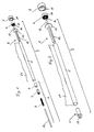
- the winding shaft 9 includes a Winding shaft 9, on which the roller blind are wound up can and from which the blind sheet 17 are handled can, several components.
- An essential part is a take-up tube 5, whose length is approximately the width of Roller blind 17 corresponds, as can be seen from the figures.
- the winding shaft 9 further includes a spring driver 6, which has a rod-shaped spring driver part 12.
- the rod-shaped driver part 12 has a cross-section Profiling that deviates from a circular shape.
- the profile For example, a polygonal shape, in particular square shape or a projected circular shape or have an oval shape.
- the deviating from the circular shape Profiling engages in one on the inside or inside wall the winding tube 5 provided corresponding profiling a, so that a rotationally fixed connection between the spring driver 6 and the winding tube 5 is produced.
- the spring driver also has a stub axle 13, which with an inner spring end 10 as a mainspring. 7 trained return spring is rotatably connected.
- the Mainspring 7 is in the form of a coil spring or scroll spring, whose particular outer turns as a dense package in one Spring housing 8 are arranged before.
- the mainspring will be formed by a spring band whose inner spring end 10, as already explained, with the stub axle 13 of the spring driver 6 is rotatably connected.
- An outer spring end 16 of Federbandes the mainspring is on the spring housing 8 at a Prop 11 supported.
- the spring housing 8 is fixed to the vehicle body arranged. In this way, the outer spring end 16 supported on the vehicle body.
- the spring driver 6 is also on the spring housing 8 in radial and supported in the axial direction.
- the spring housing 8 so be formed that on the flange 15 and a radial Guide the spring driver 6 is achieved.
- the stub axle 13 can do this in a central bore in the end wall of the Spring housing 8 be stored. This will be an exact axial alignment of the take-up tube 5 via the spring driver 6 and the spring housing 8 ensures the vehicle body.
- the stub axle 13 is coaxial with the axis of the take-up tube 5 aligned.
- the journal 1 At the other end of the take-up tube 5 is a bearing pin. 1 provided, the rotatably connected to the take-up tube 5 is and whose axis with the axis of the take-up tube 5 and the axis of the spring driver 6 is aligned.
- the journal is 1 at a vehicle-fixed not shown Storage stored. In the embodiment of FIG. 2 takes place this storage rotatable relative to the vehicle body.
- the bearing journal 1 has a stub axle 13, the in the embodiment of FIG. 2 from the vehicle-fixed bearing can be received rotatably.
- the rotatably with the end the take-up tube 5 connected part of the journal 1 and the stub axle 13 are in the embodiment of Fig. 2 made of one piece.
- the bearing pin consists 1 of several parts. These include a nut 3, which rotatably connected to the take-up tube 5 is connected.
- the internal thread the nut 3 is on an external thread of a spindle 2 screwed.
- the stub axle 13 is by an axial extending center bore of the spindle 2 and one in the take-up tube 5 inserted sleeve 4 inserted therethrough. Thereby becomes an axial alignment of the spindle 2 and the on it along the external thread rotatable nut 3 and the Sleeve 4, which form the parts of the journal 1, with the Winding tube 5 reached.
- the spindle 2 is optionally attached to the vehicle body via the stub axle 13. On this way will also be a coaxial alignment with the Federmit curriculum 6 reached at the other end of the take-up tube.
Landscapes
- Engineering & Computer Science (AREA)
- Mechanical Engineering (AREA)
- Operating, Guiding And Securing Of Roll- Type Closing Members (AREA)
- Support Devices For Sliding Doors (AREA)
- Rolls And Other Rotary Bodies (AREA)
- Window Of Vehicle (AREA)
Abstract
Description
Die Erfindung betrifft ein Fahrzeugfensterrollo mit einer Rollobahn zum zumindest teilweisen Abdecken des Fahrzeugfensters, einer Wickelwelle, auf welche die Rollobahn aufgewickelt und von welcher die Rollobahn abgewickelt werden kann, und einer Rückstellfeder, welche an der Wickelwelle angreift und die Wickelwelle in Aufwickelrichtung vorspannt.The invention relates to a vehicle window blind with a Roller blind for at least partially covering the vehicle window, a winding shaft on which the roller blind wound and from which the roller blind are unwound can, and a return spring, which on the winding shaft attacks and biases the winding shaft in the winding direction.
Aus DE 35 32 013 A1 ist ein Fahrzeugfensterrollo bekannt, bei welchem die Rollobahn mittels einer teleskopierbaren Stange, die von einem motorischen Antrieb betätigt wird, gegen die Kraft einer Rückstellfeder von der Wickelwelle in den ausgefahrenen Zustand gebracht wird.From DE 35 32 013 A1 a vehicle window blind is known, in which the roller blind by means of a telescopic Bar, which is actuated by a motor drive against the force of a return spring from the winding shaft in the extended state is brought.
Ferner ist aus US 1,630,416 ein Fensterrollo bekannt, bei welchem die Rollobahn von Hand gegen die Kraft einer Feder von der Wickelwelle abgezogen wird.Furthermore, from US 1,630,416 a window blind is known, in which the roller blind by hand against the force of a spring is deducted from the winding shaft.
Aufgabe der Erfindung ist es, eine wirkungsvolle und raumsparende Erzeugung der an der Wickelwelle angreifenden Federrückstellkraft zu erreichen.The object of the invention is to provide an effective and space-saving Generation of acting on the winding shaft spring restoring force to reach.
Diese Aufgabe wird erfindungsgemäß dadurch gelöst, dass die Rückstellfeder als Triebfeder in Form einer Spiralfeder oder Rollfeder ausgebildet ist, die mit ihrem inneren Federende an einem Wellenende der Wickelwelle angreift und mit ihrem äußeren Federende an einem fahrzeugfesten Federgehäuse abgestützt ist und dass das andere Wellenende der Wickelwelle drehbar am Fahrzeug gelagert ist. This object is achieved in that the Return spring as a mainspring in the form of a spiral spring or roll spring is formed, with its inner spring end engages at a shaft end of the winding shaft and with its outer spring end on a vehicle-fixed spring housing is supported and that the other shaft end of the winding shaft is rotatably mounted on the vehicle.
Die Triebfeder besteht aus einem Federband, welches im ungespannten Zustand die Form einer Spirale, deren Windungsabstand von innen nach außen zunimmt, aufweist. Die Triebfeder ist in einem Federgehäuse montiert, dessen Innendurchmesser bedeutend kleiner als der Außendurchmesser im entspannten Zustand ist. In diesem Zustand liegen die Windungen als dichtes Paket und mit starkem Druck an der Innenwand des Federgehäuses an. In diesem Zustand hat die Triebfeder die Form einer Rollfeder. Beim Drehen des inneren Federendes (Federkernes) wird die Feder gespannt. Dieses Spannen der Feder vollzieht sich aufgrund der unterschiedlichen Tangentialkräfte, wobei anfangs eine steil ansteigende Federkennlinie sich ergibt, die nach einigen Umdrehungen, beispielsweise zwei bis drei Umdrehungen, sich abflacht und geradlinig bis zum Sattaufzug der Triebfeder weiter verläuft. Derartige Triebfedern in Form einer Spiral- oder Rollfeder werden beispielsweise in Sicherheitsgurtaufrollautomaten verwendet, um in Bandaufzugsrichtung auf das Sicherheitsgurtband eine Vorspannung auszuüben.The mainspring consists of a spring band, which in the unstressed Condition the shape of a spiral whose winding distance from inside to outside. The mainspring is mounted in a spring housing whose inner diameter significantly smaller than the outside diameter in the relaxed one State is. In this state, the turns are as tight package and with strong pressure on the inner wall of the spring housing at. In this state, the mainspring has the Form of a scroll spring. When turning the inner spring end (Spring core), the spring is tensioned. This tightening of the Spring takes place due to the different tangential forces, initially with a steeply rising spring characteristic results after a few turns, for example two to three turns, flattening and straight continues until the Sattaufzug the mainspring. such Shoot springs in the form of a spiral or scroll spring used for example in seatbelt winders, in the tape winding direction on the seat belt webbing to exert a bias.
Zur Übertragung der Federvorspannung auf die Wickelwelle kann mit dem inneren Federende der Triebfeder ein Federmitnehmer verbunden sein, der drehfest mit einem Aufwickelrohr der Wickelwelle verbunden ist. Hierzu kann der Federmitnehmer ein Federmitnehmerteil aufweisen, welches im Querschnitt ein von der Kreisform abweichendes Profil besitzt, das in ein entsprechendes Profil an der Innenseite des Aufwickelrohres von einem Ende des Aufwickelrohres her eingreift.For transmitting the spring preload to the winding shaft can with the inner spring end of the mainspring a spring driver be connected, the rotationally fixed with a take-up tube the winding shaft is connected. For this purpose, the spring taker have a Federmitnehmerteil which in cross section has a profile deviating from the circular shape, which in a corresponding profile on the inside of the take-up tube engaging from one end of the take-up tube.
Die Wickelwelle kann zur drehbaren Lagerung am Fahrzeug einen Lagerzapfen aufweisen, der mit dem zur Rückstellfeder entgegengesetzt liegenden Rohrende des Aufwickelrohres drehfest verbunden ist. Der Lagerzapfen kann ein- oder mehrteilig ausgebildet sein. Der mehrteilig ausgebildete Lagerzapfen kann ein Innengewinde aufweisen, welches auf dem Außengewinde einer fahrzeugfesten Spindel drehbar gelagert ist. Hierdurch lässt sich eine Axialverschiebung der Wickelwelle und insbesondere des Aufwickelrohres beim Ausziehen der Rollobahn und beim Aufwickeln der Rollobahn erreichen. Der Lagerzapfen kann hierzu in axialer Richtung fest mit der Wickelwelle verbunden sein. Zur Unterstützung der axialen Verschiebbarkeit der Wickelwelle und insbesondere des Aufwickelrohres kann am Federmitnehmer ein stabförmiges Mitnehmerteil vorgesehen sein, welches das von der Kreisform abweichende Profil aufweist. Der Federmitnehmer ist vorzugsweise am Federgehäuse in radialer Richtung und gegebenenfalls in axialer Richtung abgestützt. Ferner kann der Federmitnehmer einen Achsstummel aufweisen, an welchem das innere Federende angreift. Dieser Achsstummel ist mit einem weiteren am Lagerzapfen am anderen Wellenende vorgesehenen Achsstummel ausgerichtet und zur Achse des Aufwickelrohres koaxial angeordnet. Hierdurch erreicht man eine in radialer und axialer Richtung definierte Abstützung der Wickelwelle am Fahrzeugaufbau, wobei die Triebfeder, wie schon erläutert, an einem Wellenende der Wickelwelle angreift.The winding shaft can be used for rotatable mounting on the vehicle Have bearing journal, which with the return spring opposite tube end of the take-up rotatably connected is. The journal can be one or more parts be educated. The multi-part bearing journal can have an internal thread, which on the external thread a vehicle-fixed spindle is rotatably mounted. This allows an axial displacement of the winding shaft and in particular the take-up tube when removing the roller blind and reach when winding up the roller blind. The journal can this in the axial direction fixed to the winding shaft be connected. To support the axial displacement the winding shaft and in particular the take-up tube can on the spring driver a rod-shaped driver part be provided, which deviates from the circular shape Profile. The spring taker is preferably on the spring housing in the radial direction and optionally supported in the axial direction. Furthermore, the spring taker have a stub axle, on which the inner Spring end attacks. This stub axle is with another provided on the journal on the other shaft end axle stub aligned and coaxial to the axis of the take-up tube arranged. This achieves one in radial and axial direction defined support of the winding shaft on the vehicle body, the mainspring, as already explained, engages a shaft end of the winding shaft.
Beim Abwickeln der Rollobahn liegt die Rückstellkraft der Triebfeder vorzugsweise im geradlinigen Teil der Federkennlinie. Hierzu kann beispielsweise bei voll aufgewickelter Rollobahn das innere Federende (Federkern) mit einigen, beispielsweise zwei bis drei Umdrehungen bis zum Erreichen des geradlinigen Teil der Federkennlinie gedreht und damit vorgespannt sein. Im voll aufgewickelten Zustand der Rollobahn wird dieses somit unter Vorspannung gehalten. Dabei kann die Oberkante der Rollobahn, beispielsweise über eine mit der Oberkante verbundene Leiste an einem fahrzeugfesten Anschlag anliegen. When unwinding the roller blind, the restoring force of Mainspring preferably in the straight part of the spring characteristic. For this purpose, for example, when fully wound Roller blind the inner spring end (spring core) with some, for example two to three turns until reaching the rectilinear part of the spring characteristic turned and thus biased be. In the fully wound state of the roller blind this is thus held under bias. It can the Upper edge of the roller blind, for example, one with the Top edge connected bar on a vehicle-fixed stop issue.
Das Fensterrollo kann bei den Seitenfenstern oder auch den Heckfensters eines Kraftfahrzeugs zum Einsatz kommen.The window blind can be at the side windows or the Rear window of a motor vehicle are used.
Anhand der Figuren wird an Ausführungsbeispielen die Erfindung noch näher erläutert.Based on the figures, the invention of embodiments explained in more detail.
Es zeigt
- Fig. 1
- ein erstes Ausführungsbeispiel; und
- Fig. 2
- ein zweites Ausführungsbeispiel.
- Fig. 1
- a first embodiment; and
- Fig. 2
- a second embodiment.
Die beiden Ausführungsbeispiele sind Fahrzeugfensterrollos,
welche eine Rollobahn 17 aufweisen, die zum teilweisen oder
ganzen Abdecken des Fahrzeugfensters dienen. Die Rollobahn
kann in bekannter Weise ausgebildet sein, wobei an der nicht
dargestellten Oberkante der Rollobahn 17 eine Leiste befestigt
ist, um die Rollobahn in die ausgefahrene oder aufgewickelte
Stellung zu bringen. Gegebenenfalls kann die Oberkante
der Rollobahn in unterschiedlichen Höhen durch entsprechende
Anschläge und Haltevorrichtungen, die an der mit der
Oberkante verbundenen Leiste angreifen, in der gewünschten
Auszugsposition gehalten werden.The two embodiments are vehicle window blinds,
which have a
Bei allen dargestellten Ausführungsbeispielen beinhaltet eine
Wickelwelle 9, auf welche die Rollobahn aufgewickelt werden
kann und von welcher die Rollobahn 17 abgewickelt werden
kann, mehrere Bestandteile. Ein wesentlicher Bestandteil ist
ein Aufwickelrohr 5, dessen Länge in etwa der Breite der
Rollobahn 17 entspricht, wie aus den Figuren zu ersehen ist.
Die Wickelwelle 9 beinhaltet ferner einen Federmitnehmer 6,
der ein stabförmiges Federmitnehmerteil 12 aufweist. Das
stabförmige Mitnehmerteil 12 besitzt im Querschnitt eine
Profilierung, die von einer Kreisform abweicht. Das Profil
kann beispielsweise eine mehreckige Form, insbesondere Vierkantform
oder eine mit Vorsprüngen versehene Kreisform oder
eine ovale Form haben. Die von der Kreisform abweichende
Profilierung greift in eine an der Innenseite bzw. Innenwand
des Aufwickelrohres 5 vorgesehene entsprechende Profilierung
ein, so dass eine drehfeste Verbindung zwischen dem Federmitnehmer
6 und dem Aufwickelrohr 5 hergestellt wird.In all illustrated embodiments includes a
Winding shaft 9, on which the roller blind are wound up
can and from which the
Der Federmitnehmer besitzt ferner einen Achsstummel 13, welcher
mit einem inneren Federende 10 einer als Triebfeder 7
ausgebildeten Rückstellfeder drehfest verbunden ist. Die
Triebfeder 7 liegt in Form einer Spiralfeder oder Rollfeder,
deren insbesondere äußere Windungen als dichtes Paket in einem
Federgehäuse 8 angeordnet sind, vor. Die Triebfeder wird
von einem Federband gebildet, dessen inneres Federende 10,
wie schon erläutert, mit dem Achsstummel 13 des Federmitnehmers
6 drehfest verbunden ist. Ein äußeres Federende 16 des
Federbandes der Triebfeder ist am Federgehäuse 8 an einer
Stütze 11 abgestützt. Das Federgehäuse 8 ist fest am Fahrzeugaufbau
angeordnet. Auf diese Weise wird das äußere Federende
16 am Fahrzeugaufbau abgestützt.The spring driver also has a
Der Federmitnehmer 6 ist außerdem am Federgehäuse 8 in radialer
und axialer Richtung abgestützt. Hierzu ist am Federmitnehmer
6 ein scheibenförmiger Flansch 15 einstückig vorgesehen,
welcher zumindest in axialer Richtung am Federgehäuse
8 abgestützt wird. Ferner kann das Federgehäuse 8 so
ausgebildet sein, dass über den Flansch 15 auch eine radiale
Führung des Federmitnehmers 6 erreicht wird. Der Achsstummel
13 kann hierzu in einer Mittenbohrung in der Stirnwand des
Federgehäuses 8 gelagert sein. Hierdurch wird eine exakte
axiale Ausrichtung des Aufwickelrohres 5 über den Federmitnehmer
6 und das Federgehäuse 8 am Fahrzeugaufbau gewährleistet.
Der Achsstummel 13 ist koaxial zur Achse des Aufwickelrohres
5 ausgerichtet.The
Am anderen Ende des Aufwickelrohres 5 ist ein Lagerzapfen 1
vorgesehen, der drehfest mit dem Aufwickelrohr 5 verbunden
ist und dessen Achse mit der Achse des Aufwickelrohres 5 und
der Achse des Federmitnehmers 6 ausgerichtet ist. Für die
definierte Lagerung des Wellenendes der Wickelwelle 9, welche
entgegengesetzt zur Triebfeder 7 liegt, ist der Lagerzapfen
1 an einer nicht näher dargestellten fahrzeugfesten
Lagerung gelagert. Beim Ausführungsbeispiel der Fig. 2 erfolgt
diese Lagerung drehbar gegenüber dem Fahrzeugaufbau.
Hierzu besitzt der Lagerzapfen 1 einen Achsstummel 13, der
beim Ausführungsbeispiel der Fig. 2 vom fahrzeugfesten Lager
drehbar aufgenommen werden kann. Das drehfest mit dem Ende
des Aufwickelrohres 5 verbundene Teil des Lagerzapfens 1 sowie
der Achsstummel 13 sind beim Ausführungsbeispiel der
Fig. 2 aus einem Stück hergestellt.At the other end of the take-
Beim Ausführungsbeispiel der Fig. 1 besteht der Lagerzapfen
1 aus mehreren Teilen. Diese umfassen eine Mutter 3, welche
drehfest mit dem Aufwickelrohr 5 verbunden wird. Das Innengewinde
der Mutter 3 ist auf ein Außengewinde einer Spindel
2 aufgeschraubt. Der Achsstummel 13 ist durch eine axial
verlaufende Mittenbohrung der Spindel 2 und eine in das Aufwickelrohr
5 eingesetzte Hülse 4 hindurchgesteckt. Dadurch
wird eine axiale Ausrichtung der Spindel 2 und der darauf
entlang dem Außengewinde verdrehbaren Mutter 3 sowie der
Hülse 4, welche die Teile des Lagerzapfens 1 bilden, mit dem
Aufwickelrohr 5 erreicht. Die Spindel 2 ist gegebenenfalls
über den Achsstummel 13 am Fahrzeugaufbau befestigt. Auf
diese Weise wird ferner eine koaxiale Ausrichtung mit dem
Federmitnehmer 6 am anderen Ende des Aufwickelrohres erreicht. In the embodiment of Fig. 1, the bearing pin consists
1 of several parts. These include a
Beim Drehen des Aufwickelrohres 5 beim Abziehen oder Aufwickeln
der Rollobahn 17 wird aufgrund des Schraubgewindeeingriffs
zwischen der Spindel 2 und der fest mit dem Aufwickelrohr
5 verbundenen Mutter 3 eine axiale Verschiebung des
Aufwickelrohres 5 gewährleistet. Dabei wird das andere Ende
des Aufwickelrohres 5 entlang dem stabförmigen Federmitnehmerteil
12 bewegt. When turning the winding
- 11
- Lagerzapfenpivot
- 22
- Spindelspindle
- 33
- Muttermother
- 44
- Hülseshell
- 55
- Aufwickelrohrwinding tube
- 66
- FedermitnehmerFedermitnehmer
- 77
- Triebfeder (Rückstellfeder)Mainspring (return spring)
- 88th
- Federgehäusespring housing
- 99
- Wickelwellewinding shaft
- 1010
- inneres Federendeinner spring end
- 1111
- Stützesupport
- 1212
- stabförmiges Federmitnehmerteilrod-shaped spring driver part
- 1313
- Achsstummelstub axle
- 1414
- Achsstummelstub axle
- 1515
- Flanschflange
- 1616
- äußeres Federendeouter spring end
- 1717
- Rollobahnblind web
Claims (10)
dadurch gekennzeichnet, dass die Rückstellfeder als Triebfeder (7) in Form einer Spiralfeder oder Rollfeder ausgebildet ist, die mit ihrem inneren Federende (10) am einen Wellenende der Wickelwelle (9) angreift und mit ihrem äußeren Federende (16) an einem fahrzeugfesten Federgehäuse (8) abgestützt ist, und dass das andere Wellenende der Wickelwelle (9) drehbar am Fahrzeugaufbau gelagert ist.Fahrzeugfensterrollo with a roller blind for at least partially covering the vehicle window, a winding shaft on which the roller blind wound and on which the blind can be unwound, and a return spring which engages the winding shaft and biases the winding shaft in the winding,
characterized in that the return spring is designed as a mainspring (7) in the form of a spiral spring or roll spring which engages with its inner spring end (10) at one shaft end of the winding shaft (9) and with its outer spring end (16) on a vehicle-fixed spring housing ( 8) is supported, and that the other shaft end of the winding shaft (9) is rotatably mounted on the vehicle body.
dadurch gekennzeichnet, dass die Wickelwelle (9) ein Aufwickelrohr (5) aufweist, mit welchem ein mit dem inneren Federende (10) verbundener Federmitnehmer (6) drehfest verbunden ist.Vehicle window blind according to claim 1,
characterized in that the winding shaft (9) has a take-up tube (5) with which a with the inner spring end (10) connected spring driver (6) is rotatably connected.
dadurch gekennzeichnet, dass der Federmitnehmer (6) ein Federmitnehmerteil (12) aufweist, welches ein im Querschnitt von der Kreisform abweichendes Profil aufweist, das in ein entsprechendes Profil an der Innenwand des Aufwickelrohres (5) eingreift.Vehicle window blind according to claim 1 or 2,
characterized in that the spring driver (6) has a Federmitnehmerteil (12) which has a deviating in cross-section from the circular profile, which engages in a corresponding profile on the inner wall of the take-up tube (5).
dadurch gekennzeichnet, dass die Wickelwelle (9) zur drehbaren Lagerung am Fahrzeug einen Lagerzapfen (1) aufweist, der mit dem zur Triebfeder (7) entgegengesetzt liegenden Rohrende des Aufwickelrohres (5) drehfest verbunden ist.Vehicle window blind according to one of claims 1 to 3,
characterized in that the winding shaft (9) for rotatable mounting on the vehicle has a bearing journal (1) which is rotatably connected to the drive spring (7) opposite the tube end of the take-up tube (5).
dadurch gekennzeichnet, dass der Lagerzapfen (1) ein Innengewinde aufweist, welches auf ein Außengewinde einer fahrzeugfesten Spindel (2) drehbar und axial verschiebbar aufgeschraubt ist.Vehicle window blind according to claim 4,
characterized in that the bearing journal (1) has an internal thread which is screwed on an external thread of a vehicle-fixed spindle (2) rotatable and axially displaceable.
dadurch gekennzeichnet, dass der Lagerzapfen (1) in axialer Richtung der Wickelwelle (9) fest mit der Wickelwelle (9) verbunden ist.Vehicle window blind according to claim 4 or 5,
characterized in that the bearing journal (1) in the axial direction of the winding shaft (9) is fixedly connected to the winding shaft (9).
dadurch gekennzeichnet, dass das Federmitnehmerteil (12) stabförmig ausgebildet ist, und das Aufwickelrohr (5) gegenüber dem Federmitnehmerteil (12) axial verschiebbar ist.Vehicle window blind according to one of claims 1 to 6,
characterized in that the Federmitnehmerteil (12) is rod-shaped, and the take-up tube (5) relative to the Federmitnehmerteil (12) is axially displaceable.
dadurch gekennzeichnet, dass der Federmitnehmer (6) einen Achsstummel (13) aufweist, an welchem das innere Federende (10) eingreift, und welcher mit einem weiteren am Lagerzapfen (1) vorgesehen Achsstummel (14) koaxial angeordnet ist, wobei die beiden Achsstummel (13, 14) mit der Achse des Aufwickelrohres (5) ausgerichtet sind.Vehicle window blind according to one of claims 1 to 7,
characterized in that the spring driver (6) has a stub axle (13) on which the inner spring end (10) engages, and which is arranged coaxially with a further stub axle (14) provided on the bearing pin (1), wherein the two axle stubs ( 13, 14) are aligned with the axis of the take-up tube (5).
dadurch gekennzeichnet, dass der Federmitnehmer (6) am Federgehäuse (8) in radialer und axialer Richtung abgestützt ist.Vehicle window blind according to one of claims 1 to 8,
characterized in that the spring driver (6) on the spring housing (8) is supported in the radial and axial directions.
dadurch gekennzeichnet, dass beim Abwickeln der Rollobahn (17) die Rückstellfeder der Triebfeder (7) im geradlinigen Teil der Federkennlinie liegt.Vehicle window blind according to one of claims 1 to 9,
characterized in that during unwinding of the roller blind (17), the return spring of the mainspring (7) is located in the rectilinear part of the spring characteristic.
Priority Applications (1)
| Application Number | Priority Date | Filing Date | Title |
|---|---|---|---|
| PL04030502T PL1555151T3 (en) | 2004-01-16 | 2004-12-22 | Roller blind for vehicle |
Applications Claiming Priority (2)
| Application Number | Priority Date | Filing Date | Title |
|---|---|---|---|
| DE202004000631U DE202004000631U1 (en) | 2004-01-16 | 2004-01-16 | Vehicle window blind |
| DE202004000631U | 2004-01-16 |
Publications (4)
| Publication Number | Publication Date |
|---|---|
| EP1555151A2 true EP1555151A2 (en) | 2005-07-20 |
| EP1555151A3 EP1555151A3 (en) | 2006-07-19 |
| EP1555151B1 EP1555151B1 (en) | 2008-05-21 |
| EP1555151B2 EP1555151B2 (en) | 2011-01-05 |
Family
ID=32049867
Family Applications (1)
| Application Number | Title | Priority Date | Filing Date |
|---|---|---|---|
| EP04030502A Expired - Lifetime EP1555151B2 (en) | 2004-01-16 | 2004-12-22 | Roller blind for vehicle |
Country Status (4)
| Country | Link |
|---|---|
| EP (1) | EP1555151B2 (en) |
| AT (1) | ATE396075T1 (en) |
| DE (2) | DE202004000631U1 (en) |
| PL (1) | PL1555151T3 (en) |
Cited By (2)
| Publication number | Priority date | Publication date | Assignee | Title |
|---|---|---|---|---|
| EP2062767A1 (en) | 2007-11-22 | 2009-05-27 | HS Products Engineering GmbH | Vehicle roller blind with tensioning spring and spring core |
| CN110691706A (en) * | 2017-05-30 | 2020-01-14 | 韦巴斯托股份公司 | Roller blind arrangement for a motor vehicle |
Families Citing this family (5)
| Publication number | Priority date | Publication date | Assignee | Title |
|---|---|---|---|---|
| DE102004049167A1 (en) † | 2004-10-08 | 2006-04-20 | Hs Products Engineering Gmbh | Window roller blind for a vehicle window |
| FR2899535B1 (en) * | 2006-04-06 | 2009-04-10 | Cera | TABLET FOR A MOTOR VEHICLE INCLUDING A ROLL-UP CURTAIN |
| DE102006028351A1 (en) | 2006-06-20 | 2007-12-27 | Hs Products Engineering Gmbh | Window roller blind for a vehicle window |
| DE102008016909B4 (en) * | 2008-03-25 | 2010-12-02 | Bos Gmbh & Co. Kg | window treatment |
| DE102015106528A1 (en) | 2015-04-28 | 2016-11-03 | Lisa Dräxlmaier GmbH | Vehicle window shade with cable pull concept and drive of the cable pull via toothed belt |
Citations (2)
| Publication number | Priority date | Publication date | Assignee | Title |
|---|---|---|---|---|
| US1630416A (en) | 1926-06-25 | 1927-05-31 | Auto Roller Awning Mfg Company | Awning |
| DE3532013A1 (en) | 1985-09-07 | 1987-03-19 | Hueppe Gmbh | Blind arrangement for covering a window, especially the rear window of a motor vehicle |
Family Cites Families (13)
| Publication number | Priority date | Publication date | Assignee | Title |
|---|---|---|---|---|
| US1823290A (en) * | 1924-02-05 | 1931-09-15 | Peter P Tyvoll | Window screen for closed automobiles |
| US1578641A (en) * | 1924-10-31 | 1926-03-30 | Norbert W Bywater | Side inclosure for automobiles |
| FR1184013A (en) * | 1957-10-07 | 1959-07-16 | Sun protection device, in particular for motor vehicles | |
| DE7904967U1 (en) † | 1979-02-22 | 1990-03-01 | Velux GmbH - Bauzubehör, 2000 Hamburg | Roller shutters |
| US4482137A (en) † | 1982-12-10 | 1984-11-13 | Irvin Industries, Inc. | Compartment shade |
| DE3813153A1 (en) † | 1988-04-20 | 1989-11-02 | Happich Gmbh Gebr | WINDOW ROLLER |
| FR2631374B1 (en) † | 1988-05-13 | 1990-08-17 | Cantin Coulaud Ste Nle | WINDING BLINDS, PARTICULARLY FOR PARALLELOGRAM-SHAPED BAYS |
| US5135279A (en) † | 1991-07-11 | 1992-08-04 | Annetta Beatty | Windshiled shade assembly for motor vehicles |
| US5464052A (en) † | 1993-11-08 | 1995-11-07 | Takata, Inc. | Security shade with a motor spring subassembly |
| US5934354A (en) * | 1997-10-23 | 1999-08-10 | Irvin Automotive Products, Inc. | Security shade support assembly |
| FR2823791B1 (en) * | 2001-04-18 | 2004-02-13 | Cera | WINDING SPRING CURTAIN |
| DE10132080C1 (en) * | 2001-07-05 | 2002-07-25 | Butz Peter Verwaltung | Protective and/or covering blind, for minibus, has drive device reducing return moment on blind up to first pull-out length but applying higher return moment after this |
| KR100425005B1 (en) * | 2001-10-10 | 2004-03-30 | 코리아에프티 주식회사 | A sun-shade apparatus for an antomobile |
-
2004
- 2004-01-16 DE DE202004000631U patent/DE202004000631U1/en not_active Expired - Lifetime
- 2004-12-22 EP EP04030502A patent/EP1555151B2/en not_active Expired - Lifetime
- 2004-12-22 PL PL04030502T patent/PL1555151T3/en unknown
- 2004-12-22 AT AT04030502T patent/ATE396075T1/en active
- 2004-12-22 DE DE502004007218T patent/DE502004007218D1/en not_active Expired - Lifetime
Patent Citations (2)
| Publication number | Priority date | Publication date | Assignee | Title |
|---|---|---|---|---|
| US1630416A (en) | 1926-06-25 | 1927-05-31 | Auto Roller Awning Mfg Company | Awning |
| DE3532013A1 (en) | 1985-09-07 | 1987-03-19 | Hueppe Gmbh | Blind arrangement for covering a window, especially the rear window of a motor vehicle |
Cited By (4)
| Publication number | Priority date | Publication date | Assignee | Title |
|---|---|---|---|---|
| EP2062767A1 (en) | 2007-11-22 | 2009-05-27 | HS Products Engineering GmbH | Vehicle roller blind with tensioning spring and spring core |
| DE102007056297A1 (en) | 2007-11-22 | 2009-05-28 | Hs Products Engineering Gmbh | Vehicle blind with spring roll and spring heart |
| CN110691706A (en) * | 2017-05-30 | 2020-01-14 | 韦巴斯托股份公司 | Roller blind arrangement for a motor vehicle |
| CN110691706B (en) * | 2017-05-30 | 2022-09-09 | 韦巴斯托股份公司 | Roller shutter structures for motor vehicles |
Also Published As
| Publication number | Publication date |
|---|---|
| EP1555151B2 (en) | 2011-01-05 |
| EP1555151A3 (en) | 2006-07-19 |
| DE502004007218D1 (en) | 2008-07-03 |
| EP1555151B1 (en) | 2008-05-21 |
| PL1555151T3 (en) | 2009-01-30 |
| DE202004000631U1 (en) | 2004-03-18 |
| ATE396075T1 (en) | 2008-06-15 |
Similar Documents
| Publication | Publication Date | Title |
|---|---|---|
| EP1904711B1 (en) | Winding shaft for a roller blind device | |
| DE19530310C2 (en) | Window blind | |
| DE60215941T2 (en) | BRAKING DEVICE FOR ROLLOS AND THE SIMILAR | |
| EP3727994B1 (en) | Motor-adjustable steering column for a motor vehicle | |
| DE2900104A1 (en) | HOUSING ASSEMBLY FOR A PRE-TENSIONED SPRING OF A SAFETY BELT RETRACTING DEVICE | |
| DE19820641B4 (en) | Gurtaufwickeleinrichtung | |
| EP3122612B1 (en) | Steering column for a motor vehicle | |
| DE112012004799B4 (en) | seat belt retractor | |
| EP2088229B1 (en) | Sewing machine and winding device for such a sewing machine | |
| WO2022002768A1 (en) | Steering column for a motor vehicle and method for adjusting a steering column | |
| EP1555151B2 (en) | Roller blind for vehicle | |
| EP3686390B1 (en) | Roller protective cover | |
| DE102004015825B4 (en) | Belt retractor for a vehicle seat belt | |
| DE10158428A1 (en) | Roller blind, especially a vehicle sun blind, has a coil spring in the roller blind shaft and around the connecting shaft, to give low and consistent setting forces to position the blind | |
| EP2112105B1 (en) | Roller tensioning device, printer and method for tensioning a roller | |
| EP3286043B1 (en) | Belt retractor | |
| WO2008135018A2 (en) | Blind device, particularly for a sunroof system | |
| EP2138621B1 (en) | Sewing machine and spool device for operating such a sewing machine | |
| WO2014053374A1 (en) | Vehicle seat | |
| DE102014016308A1 (en) | A belt retractor and method for controlling a webbing withdrawal force in a belt retractor of a vehicle occupant restraint system | |
| DE102004021776A1 (en) | Apparatus and method for forming helices from a thread | |
| EP0005521A1 (en) | Automatic retracting device for safety belts | |
| DE102008009770B4 (en) | Belt retractor for a vehicle seat belt | |
| DE102008038839B4 (en) | Belt tensioner for a safety belt system | |
| DE102019133141A1 (en) | Tensioner tube for a belt tensioner |
Legal Events
| Date | Code | Title | Description |
|---|---|---|---|
| PUAI | Public reference made under article 153(3) epc to a published international application that has entered the european phase |
Free format text: ORIGINAL CODE: 0009012 |
|
| AK | Designated contracting states |
Kind code of ref document: A2 Designated state(s): AT BE BG CH CY CZ DE DK EE ES FI FR GB GR HU IE IS IT LI LT LU MC NL PL PT RO SE SI SK TR |
|
| AX | Request for extension of the european patent |
Extension state: AL BA HR LV MK YU |
|
| PUAL | Search report despatched |
Free format text: ORIGINAL CODE: 0009013 |
|
| AK | Designated contracting states |
Kind code of ref document: A3 Designated state(s): AT BE BG CH CY CZ DE DK EE ES FI FR GB GR HU IE IS IT LI LT LU MC NL PL PT RO SE SI SK TR |
|
| AX | Request for extension of the european patent |
Extension state: AL BA HR LV MK YU |
|
| 17P | Request for examination filed |
Effective date: 20070119 |
|
| AKX | Designation fees paid |
Designated state(s): AT BE BG CH CY CZ DE DK EE ES FI FR GB GR HU IE IS IT LI LT LU MC NL PL PT RO SE SI SK TR |
|
| 17Q | First examination report despatched |
Effective date: 20070618 |
|
| GRAP | Despatch of communication of intention to grant a patent |
Free format text: ORIGINAL CODE: EPIDOSNIGR1 |
|
| GRAS | Grant fee paid |
Free format text: ORIGINAL CODE: EPIDOSNIGR3 |
|
| GRAA | (expected) grant |
Free format text: ORIGINAL CODE: 0009210 |
|
| AK | Designated contracting states |
Kind code of ref document: B1 Designated state(s): AT BE BG CH CY CZ DE DK EE ES FI FR GB GR HU IE IS IT LI LT LU MC NL PL PT RO SE SI SK TR |
|
| REG | Reference to a national code |
Ref country code: GB Ref legal event code: FG4D Free format text: NOT ENGLISH |
|
| REG | Reference to a national code |
Ref country code: CH Ref legal event code: EP |
|
| REF | Corresponds to: |
Ref document number: 502004007218 Country of ref document: DE Date of ref document: 20080703 Kind code of ref document: P |
|
| REG | Reference to a national code |
Ref country code: IE Ref legal event code: FG4D Free format text: LANGUAGE OF EP DOCUMENT: GERMAN |
|
| PG25 | Lapsed in a contracting state [announced via postgrant information from national office to epo] |
Ref country code: SI Free format text: LAPSE BECAUSE OF FAILURE TO SUBMIT A TRANSLATION OF THE DESCRIPTION OR TO PAY THE FEE WITHIN THE PRESCRIBED TIME-LIMIT Effective date: 20080521 |
|
| PG25 | Lapsed in a contracting state [announced via postgrant information from national office to epo] |
Ref country code: FI Free format text: LAPSE BECAUSE OF FAILURE TO SUBMIT A TRANSLATION OF THE DESCRIPTION OR TO PAY THE FEE WITHIN THE PRESCRIBED TIME-LIMIT Effective date: 20080521 Ref country code: ES Free format text: LAPSE BECAUSE OF FAILURE TO SUBMIT A TRANSLATION OF THE DESCRIPTION OR TO PAY THE FEE WITHIN THE PRESCRIBED TIME-LIMIT Effective date: 20080901 |
|
| NLV1 | Nl: lapsed or annulled due to failure to fulfill the requirements of art. 29p and 29m of the patents act | ||
| PG25 | Lapsed in a contracting state [announced via postgrant information from national office to epo] |
Ref country code: NL Free format text: LAPSE BECAUSE OF FAILURE TO SUBMIT A TRANSLATION OF THE DESCRIPTION OR TO PAY THE FEE WITHIN THE PRESCRIBED TIME-LIMIT Effective date: 20080521 |
|
| PG25 | Lapsed in a contracting state [announced via postgrant information from national office to epo] |
Ref country code: IS Free format text: LAPSE BECAUSE OF FAILURE TO SUBMIT A TRANSLATION OF THE DESCRIPTION OR TO PAY THE FEE WITHIN THE PRESCRIBED TIME-LIMIT Effective date: 20080921 |
|
| REG | Reference to a national code |
Ref country code: IE Ref legal event code: FD4D |
|
| PG25 | Lapsed in a contracting state [announced via postgrant information from national office to epo] |
Ref country code: LT Free format text: LAPSE BECAUSE OF FAILURE TO SUBMIT A TRANSLATION OF THE DESCRIPTION OR TO PAY THE FEE WITHIN THE PRESCRIBED TIME-LIMIT Effective date: 20080521 Ref country code: CZ Free format text: LAPSE BECAUSE OF FAILURE TO SUBMIT A TRANSLATION OF THE DESCRIPTION OR TO PAY THE FEE WITHIN THE PRESCRIBED TIME-LIMIT Effective date: 20080521 Ref country code: SE Free format text: LAPSE BECAUSE OF FAILURE TO SUBMIT A TRANSLATION OF THE DESCRIPTION OR TO PAY THE FEE WITHIN THE PRESCRIBED TIME-LIMIT Effective date: 20080821 Ref country code: DK Free format text: LAPSE BECAUSE OF FAILURE TO SUBMIT A TRANSLATION OF THE DESCRIPTION OR TO PAY THE FEE WITHIN THE PRESCRIBED TIME-LIMIT Effective date: 20080521 Ref country code: PT Free format text: LAPSE BECAUSE OF FAILURE TO SUBMIT A TRANSLATION OF THE DESCRIPTION OR TO PAY THE FEE WITHIN THE PRESCRIBED TIME-LIMIT Effective date: 20081021 Ref country code: IE Free format text: LAPSE BECAUSE OF FAILURE TO SUBMIT A TRANSLATION OF THE DESCRIPTION OR TO PAY THE FEE WITHIN THE PRESCRIBED TIME-LIMIT Effective date: 20080521 |
|
| REG | Reference to a national code |
Ref country code: PL Ref legal event code: T3 |
|
| PG25 | Lapsed in a contracting state [announced via postgrant information from national office to epo] |
Ref country code: RO Free format text: LAPSE BECAUSE OF FAILURE TO SUBMIT A TRANSLATION OF THE DESCRIPTION OR TO PAY THE FEE WITHIN THE PRESCRIBED TIME-LIMIT Effective date: 20080521 Ref country code: SK Free format text: LAPSE BECAUSE OF FAILURE TO SUBMIT A TRANSLATION OF THE DESCRIPTION OR TO PAY THE FEE WITHIN THE PRESCRIBED TIME-LIMIT Effective date: 20080521 |
|
| PLBI | Opposition filed |
Free format text: ORIGINAL CODE: 0009260 |
|
| REG | Reference to a national code |
Ref country code: HU Ref legal event code: AG4A Ref document number: E004154 Country of ref document: HU |
|
| 26 | Opposition filed |
Opponent name: BOS GMBH & CO. KG WORLDWIDE HEADQUARTERS STUTTGART Effective date: 20090220 |
|
| PLAX | Notice of opposition and request to file observation + time limit sent |
Free format text: ORIGINAL CODE: EPIDOSNOBS2 |
|
| PG25 | Lapsed in a contracting state [announced via postgrant information from national office to epo] |
Ref country code: BG Free format text: LAPSE BECAUSE OF FAILURE TO SUBMIT A TRANSLATION OF THE DESCRIPTION OR TO PAY THE FEE WITHIN THE PRESCRIBED TIME-LIMIT Effective date: 20080821 Ref country code: EE Free format text: LAPSE BECAUSE OF FAILURE TO SUBMIT A TRANSLATION OF THE DESCRIPTION OR TO PAY THE FEE WITHIN THE PRESCRIBED TIME-LIMIT Effective date: 20080521 |
|
| BERE | Be: lapsed |
Owner name: HS PRODUCTS ENGINEERING G.M.B.H. Effective date: 20081231 |
|
| PG25 | Lapsed in a contracting state [announced via postgrant information from national office to epo] |
Ref country code: MC Free format text: LAPSE BECAUSE OF NON-PAYMENT OF DUE FEES Effective date: 20081231 |
|
| REG | Reference to a national code |
Ref country code: CH Ref legal event code: PL |
|
| GBPC | Gb: european patent ceased through non-payment of renewal fee |
Effective date: 20081222 |
|
| PLBB | Reply of patent proprietor to notice(s) of opposition received |
Free format text: ORIGINAL CODE: EPIDOSNOBS3 |
|
| PG25 | Lapsed in a contracting state [announced via postgrant information from national office to epo] |
Ref country code: BE Free format text: LAPSE BECAUSE OF NON-PAYMENT OF DUE FEES Effective date: 20081231 |
|
| PG25 | Lapsed in a contracting state [announced via postgrant information from national office to epo] |
Ref country code: LI Free format text: LAPSE BECAUSE OF NON-PAYMENT OF DUE FEES Effective date: 20081231 Ref country code: CH Free format text: LAPSE BECAUSE OF NON-PAYMENT OF DUE FEES Effective date: 20081231 |
|
| PG25 | Lapsed in a contracting state [announced via postgrant information from national office to epo] |
Ref country code: GB Free format text: LAPSE BECAUSE OF NON-PAYMENT OF DUE FEES Effective date: 20081222 |
|
| PG25 | Lapsed in a contracting state [announced via postgrant information from national office to epo] |
Ref country code: PL Free format text: LAPSE BECAUSE OF NON-PAYMENT OF DUE FEES Effective date: 20081222 |
|
| REG | Reference to a national code |
Ref country code: PL Ref legal event code: LAPE |
|
| PG25 | Lapsed in a contracting state [announced via postgrant information from national office to epo] |
Ref country code: CY Free format text: LAPSE BECAUSE OF FAILURE TO SUBMIT A TRANSLATION OF THE DESCRIPTION OR TO PAY THE FEE WITHIN THE PRESCRIBED TIME-LIMIT Effective date: 20080521 Ref country code: LU Free format text: LAPSE BECAUSE OF NON-PAYMENT OF DUE FEES Effective date: 20081222 |
|
| PG25 | Lapsed in a contracting state [announced via postgrant information from national office to epo] |
Ref country code: TR Free format text: LAPSE BECAUSE OF FAILURE TO SUBMIT A TRANSLATION OF THE DESCRIPTION OR TO PAY THE FEE WITHIN THE PRESCRIBED TIME-LIMIT Effective date: 20080521 |
|
| PG25 | Lapsed in a contracting state [announced via postgrant information from national office to epo] |
Ref country code: GR Free format text: LAPSE BECAUSE OF FAILURE TO SUBMIT A TRANSLATION OF THE DESCRIPTION OR TO PAY THE FEE WITHIN THE PRESCRIBED TIME-LIMIT Effective date: 20080822 |
|
| PUAH | Patent maintained in amended form |
Free format text: ORIGINAL CODE: 0009272 |
|
| STAA | Information on the status of an ep patent application or granted ep patent |
Free format text: STATUS: PATENT MAINTAINED AS AMENDED |
|
| 27A | Patent maintained in amended form |
Effective date: 20110105 |
|
| AK | Designated contracting states |
Kind code of ref document: B2 Designated state(s): AT BE BG CH CY CZ DE DK EE ES FI FR GB GR HU IE IS IT LI LT LU MC NL PL PT RO SE SI SK TR |
|
| REG | Reference to a national code |
Ref country code: DE Ref legal event code: R082 Ref document number: 502004007218 Country of ref document: DE Representative=s name: BALS & VOGEL PATENTANWAELTE, DE |
|
| REG | Reference to a national code |
Ref country code: DE Ref legal event code: R082 Ref document number: 502004007218 Country of ref document: DE Representative=s name: BALS & VOGEL PATENTANWAELTE, DE |
|
| PG25 | Lapsed in a contracting state [announced via postgrant information from national office to epo] |
Ref country code: PL Free format text: LAPSE BECAUSE OF FAILURE TO SUBMIT A TRANSLATION OF THE DESCRIPTION OR TO PAY THE FEE WITHIN THE PRESCRIBED TIME-LIMIT Effective date: 20080521 |
|
| PG25 | Lapsed in a contracting state [announced via postgrant information from national office to epo] |
Ref country code: IT Free format text: LAPSE BECAUSE OF NON-PAYMENT OF DUE FEES Effective date: 20081222 |
|
| REG | Reference to a national code |
Ref country code: FR Ref legal event code: PLFP Year of fee payment: 12 |
|
| REG | Reference to a national code |
Ref country code: FR Ref legal event code: PLFP Year of fee payment: 13 |
|
| REG | Reference to a national code |
Ref country code: FR Ref legal event code: PLFP Year of fee payment: 14 |
|
| REG | Reference to a national code |
Ref country code: DE Ref legal event code: R082 Ref document number: 502004007218 Country of ref document: DE Representative=s name: MATHYS & SQUIRE EUROPE PATENTANWAELTE PARTNERS, DE |
|
| PGFP | Annual fee paid to national office [announced via postgrant information from national office to epo] |
Ref country code: FR Payment date: 20230116 Year of fee payment: 19 Ref country code: AT Payment date: 20230118 Year of fee payment: 19 |
|
| PGFP | Annual fee paid to national office [announced via postgrant information from national office to epo] |
Ref country code: HU Payment date: 20230118 Year of fee payment: 19 Ref country code: DE Payment date: 20230130 Year of fee payment: 19 |
|
| REG | Reference to a national code |
Ref country code: DE Ref legal event code: R119 Ref document number: 502004007218 Country of ref document: DE |
|
| REG | Reference to a national code |
Ref country code: AT Ref legal event code: MM01 Ref document number: 396075 Country of ref document: AT Kind code of ref document: T Effective date: 20231222 |
|
| PG25 | Lapsed in a contracting state [announced via postgrant information from national office to epo] |
Ref country code: DE Free format text: LAPSE BECAUSE OF NON-PAYMENT OF DUE FEES Effective date: 20240702 |
|
| PG25 | Lapsed in a contracting state [announced via postgrant information from national office to epo] |
Ref country code: FR Free format text: LAPSE BECAUSE OF NON-PAYMENT OF DUE FEES Effective date: 20231231 |
|
| PG25 | Lapsed in a contracting state [announced via postgrant information from national office to epo] |
Ref country code: AT Free format text: LAPSE BECAUSE OF NON-PAYMENT OF DUE FEES Effective date: 20231222 |
|
| PG25 | Lapsed in a contracting state [announced via postgrant information from national office to epo] |
Ref country code: HU Free format text: LAPSE BECAUSE OF NON-PAYMENT OF DUE FEES Effective date: 20231223 |
|
| PG25 | Lapsed in a contracting state [announced via postgrant information from national office to epo] |
Ref country code: HU Free format text: LAPSE BECAUSE OF NON-PAYMENT OF DUE FEES Effective date: 20231223 Ref country code: FR Free format text: LAPSE BECAUSE OF NON-PAYMENT OF DUE FEES Effective date: 20231231 Ref country code: DE Free format text: LAPSE BECAUSE OF NON-PAYMENT OF DUE FEES Effective date: 20240702 Ref country code: AT Free format text: LAPSE BECAUSE OF NON-PAYMENT OF DUE FEES Effective date: 20231222 |