EP1555126B1 - Maintenance mechanism for inkjet printer - Google Patents
Maintenance mechanism for inkjet printer Download PDFInfo
- Publication number
- EP1555126B1 EP1555126B1 EP03751374A EP03751374A EP1555126B1 EP 1555126 B1 EP1555126 B1 EP 1555126B1 EP 03751374 A EP03751374 A EP 03751374A EP 03751374 A EP03751374 A EP 03751374A EP 1555126 B1 EP1555126 B1 EP 1555126B1
- Authority
- EP
- European Patent Office
- Prior art keywords
- claw
- slide member
- carriage
- slide
- maintenance mechanism
- Prior art date
- Legal status (The legal status is an assumption and is not a legal conclusion. Google has not performed a legal analysis and makes no representation as to the accuracy of the status listed.)
- Expired - Lifetime
Links
- 230000008531 maintenance mechanism Effects 0.000 title claims description 49
- 210000000078 claw Anatomy 0.000 claims abstract description 90
- 238000000034 method Methods 0.000 claims description 12
- 230000006835 compression Effects 0.000 claims description 6
- 238000007906 compression Methods 0.000 claims description 6
- 230000002452 interceptive effect Effects 0.000 abstract 1
- 238000010586 diagram Methods 0.000 description 10
- 239000002184 metal Substances 0.000 description 7
- 238000012423 maintenance Methods 0.000 description 6
- 238000013016 damping Methods 0.000 description 5
- 229920003002 synthetic resin Polymers 0.000 description 4
- 239000000057 synthetic resin Substances 0.000 description 4
- 238000004140 cleaning Methods 0.000 description 3
- 239000013013 elastic material Substances 0.000 description 3
- 238000004519 manufacturing process Methods 0.000 description 3
- 230000000694 effects Effects 0.000 description 2
- 229910001335 Galvanized steel Inorganic materials 0.000 description 1
- 229920006311 Urethane elastomer Polymers 0.000 description 1
- 239000000470 constituent Substances 0.000 description 1
- 238000001035 drying Methods 0.000 description 1
- 239000000428 dust Substances 0.000 description 1
- 239000008397 galvanized steel Substances 0.000 description 1
- 239000000463 material Substances 0.000 description 1
- 238000000465 moulding Methods 0.000 description 1
- 239000010935 stainless steel Substances 0.000 description 1
- 229910001220 stainless steel Inorganic materials 0.000 description 1
Images

Classifications
-
- B—PERFORMING OPERATIONS; TRANSPORTING
- B41—PRINTING; LINING MACHINES; TYPEWRITERS; STAMPS
- B41J—TYPEWRITERS; SELECTIVE PRINTING MECHANISMS, i.e. MECHANISMS PRINTING OTHERWISE THAN FROM A FORME; CORRECTION OF TYPOGRAPHICAL ERRORS
- B41J2/00—Typewriters or selective printing mechanisms characterised by the printing or marking process for which they are designed
- B41J2/005—Typewriters or selective printing mechanisms characterised by the printing or marking process for which they are designed characterised by bringing liquid or particles selectively into contact with a printing material
- B41J2/01—Ink jet
- B41J2/135—Nozzles
- B41J2/165—Prevention or detection of nozzle clogging, e.g. cleaning, capping or moistening for nozzles
- B41J2/16517—Cleaning of print head nozzles
- B41J2/16535—Cleaning of print head nozzles using wiping constructions
- B41J2/16544—Constructions for the positioning of wipers
-
- B—PERFORMING OPERATIONS; TRANSPORTING
- B41—PRINTING; LINING MACHINES; TYPEWRITERS; STAMPS
- B41J—TYPEWRITERS; SELECTIVE PRINTING MECHANISMS, i.e. MECHANISMS PRINTING OTHERWISE THAN FROM A FORME; CORRECTION OF TYPOGRAPHICAL ERRORS
- B41J2/00—Typewriters or selective printing mechanisms characterised by the printing or marking process for which they are designed
- B41J2/005—Typewriters or selective printing mechanisms characterised by the printing or marking process for which they are designed characterised by bringing liquid or particles selectively into contact with a printing material
- B41J2/01—Ink jet
- B41J2/135—Nozzles
- B41J2/165—Prevention or detection of nozzle clogging, e.g. cleaning, capping or moistening for nozzles
- B41J2/16517—Cleaning of print head nozzles
- B41J2002/16576—Cleaning means pushed or actuated by print head movement
Definitions
- the present invention relates to a maintenance mechanism for an ink jet printer which is of a type in which an ink cartridge is mounted on a carriage.
- an ink jet printer of a type in which an ink cartridge is mounted on a carriage is equipped with a maintenance mechanism which performs wiping operation for cleaning a printhead of the ink cartridge and capping operation for preventing the printhead from drying out.
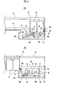
- FIG. 6 is a diagram showing an example of a conventional ink jet printer maintenance mechanism.
- ink cartridges 51 are (detachably) mounted on a carriage 52 which is slidably supported by a metal frame 61 of an apparatus body. Guided by a guide shaft 62, the carriage 52 moves back and forth along a main scanning direction to allow the ink cartridges 51 to perform a print job.
- Caps 53 for capping printheads of the ink cartridges 51 and wipers 54 for wiping the printheads are held by a slide member 56.
- Projections 56b of the slide member 56 are loosely fitted in guide holes 55b formed in a base member 55 which is fixed to the apparatus body such that the slide member 56 can slide obliquely leftward and rightward.
- a claw member 57 for locking the slide member 56 during wiping operation is swingably supported on the slide member 56 via a pivot 57a.
- the claw member 57 is always biased clockwise as illustrated by a tension spring 59, whereby the slide member 56 is biased leftward down as illustrated.
- FIG. 6(A) shows a condition in which the heads of the ink cartridges 51 are capped by the caps 53.
- the slide member 56 is connected to a right side portion of the carriage 52 via a slide member/carrier joint part 56a and pushed up to an uppermost position.
- FIG. 6(B) shows a condition in which the ink jet printer has transferred to a state of performing a print job.
- the slide member 56 is brought back obliquely leftward down by a tensile force exerted by the tension spring 59 and stops at a lowermost position after passing the wiper positions.
- the claw member 57 moves leftward and goes into a state in which the claw member 57 does not mutually interfere with a protruding part 52a which is attached to a lower-right portion of the carriage 52, where the carriage 52 is allowed to move to a print position as illustrated.
- the slide member 56 is once locked by the claw member 57 at about a mid-length position of each guide hole 55b in the base member 55 during wiping operation.
- the protruding part 52a of the carriage 52 meshes with the projecting part of the claw member 57 and the slide member 56 is unlocked subsequently before the wipers 54 wipe entire nozzle faces of the ink cartridges 51, the wipers 54 descend obliquely leftward down together with the slide member 56, causing a risk of inadequate wiping of the nozzle faces as a consequence.
- the claw member 57 is located closer to the sheet transport area than the wipers 54 during a printing process, so that it is necessary to enlarge the interval between the sheet transport area and the wipers 54. It is therefore difficult to reduce the width of the apparatus as mentioned above.
- an ink jet printer of a type in which an ink cartridge is mounted on a carriage has not conventionally been provided with any damper placed between a main chassis and a slide member for maintenance in a moving direction of the carriage. For this reason, an inertial force of the slide member for maintenance would be transmitted directly to the main chassis or a main body when the slide member for maintenance returns back to its original position, causing severe vibration and colliding sound.
- the present invention has been made in light of such circumstances. Accordingly, it is an object of the invention to provide an ink jet printer maintenance mechanism which makes it possible to reduce apparatus width and alleviate vibration of the maintenance mechanism and colliding sound caused thereby at reversing motion of a carriage.
- US 6,109,726 describes a maintenance mechanism according to the preamble of claim 1, wherein a case is disposed at a service area of the ink jet printer, a capping member is moved along first guide slots formed at the case by a carriage moved to the service area, a wiping member is moved along second guide slots and along a slope guiding surface of a pair of guide plates of the case by the cappping member and the wiping member has a wiper for cleaning a surface of a nozzle while the nozzle is moved toward a printing area and the cap is returned to an initial position thereof.
- the claw member for securing the slide member to the base member is swingably supported on the base member during the wiping operation and the claw member is forced downward by the claw push-down projecting part of the slide member in the printing process to thereby avoid mutual interference between the claw member and the carriage. Therefore, it is possible to achieve a reduction in the width of an apparatus.
- a maintenance mechanism for an ink jet printer is characterized in that the position of the aforesaid claw member during the aforesaid printing process is set lower than a sheet surface.
- the claw member stop position during the printing process is set lower than the sheet surface, so that it is possible to cause the claw member and the wiper to be positioned at a location immediately beneath the sheet. Specifically, it becomes possible to cause the position of the wiper and a sheet transport area to overlap. This makes it possible to achieve a further reduction in the width of the apparatus.
- a maintenance mechanism for an ink jet printer is characterized in that the maintenance mechanism is provided with a damper for preventing an inertial force of the aforesaid slide member caused by the returning motion thereof back to the aforesaid specified position from being transmitted directly to the aforesaid base member and the apparatus body.
- a maintenance mechanism for an ink jet printer is characterized in that the aforesaid slide member is provided with a fixing part to which the aforesaid wiper and the aforesaid damper are integrally fixed.
- the wiper and the damper are integrally fixed to the fixing part of the slide member, so that the damper can be easily installed.
- a maintenance mechanism for an ink jet printer is characterized in that the aforesaid damper is made of a compression spring having a shape which makes it possible to fix the aforesaid damper to the aforesaid fixing part.
- a maintenance mechanism for an ink jet printer is characterized in that the aforesaid wiper is made of an elastic member having a shape which makes it possible to fix the aforesaid wiper after the aforesaid damper has been fixed to the aforesaid fixing part.
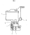
- FIG. 1 is a diagram showing the basic structure of a carriage and a maintenance mechanism of an ink jet printer according to one embodiment of the present invention, in which FIG. 1(A) is a plan view showing the carriage accommodating an ink cartridge having printhead and the maintenance mechanism for wiping and capping the printhead, FIG. 1(B) is a sectional view taken along a line A-A of FIG. 1(A), and FIG. 1(C) is a sectional view taken along a line B-B of FIG. 1(A) .
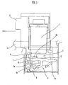
- FIG. 2 is a side view of the carriage and the maintenance mechanism shown in FIG. 1 .
- Designated by 1 is the ink cartridge in which the 1-pen type printhead (not shown) is integrally formed.
- Designated by 2 is the carriage made of molded synthetic resin, for example, for carrying the ink cartridge 1.
- Designated by 2a is an unlocking protruding part jutting out downward from the bottom of the carriage 2.
- Designated by 3 is a cap made of an elastic material like synthetic resin, for example, for covering the printhead at a printing standby position.
- Designated by 4 is a wiper made of an elastic material like urethane rubber for wiping out ink, dust, etc. adhering to a surface of the printhead.
- Designated by 6 is a slide member equipped with the cap 3 and the wiper 4.
- Designated by 5 is a base member for sliding the slide member.
- Designated by 7 is a claw member for locking the slide member 6 onto the base member 5 while the printhead is being wiped.
- the base member 5 designated by 5a are guide holes formed as integral parts of the base member for guiding the slide member 6.
- the slide member 6, designated by 6a are guided projecting parts to be guided by the guide holes 5a, the guided projecting parts 6a being integrally formed on the slide member 6, designated by 6b is a slide member/carriage joint part which is formed such that the carriage 2 becomes engaged with a protruding part provided underneath the carriage 2 when the carriage 2 moves to the printing standby position, and designated by 6c is a lock-on claw which becomes engaged with the claw member 7 to lock the slide member 6 onto the base member 5.
- Designated by 8 is claw biasing means made of a tension spring mounted between the claw member 7 and the base member 5.
- Designated by 9 is slide biasing means made of a tension spring mounted between the slide member 6 and the base member 5.
- Designated by 10 is a guide shaft constructed of a stainless steel material, for example, for guiding the carriage 2 along a main scanning direction in a stable fashion.
- Designated by 11 is a metal frame (main chassis) constructed of a galvanized steel plate, for example, and provided in an apparatus body for accommodating constituent components of the ink jet printer.
- Designated by 12 is a damper constructed of a compression spring, for example, for preventing an inertial force of the slide member 6 caused by its returning motion from being transmitted directly to the base member 5.
- the carriage 2 has the base member 5 having the movable slide member 6 and the guide holes 5a and the claw member 7 for locking the slide member 6 at the wiper position, and the cap 3 and the wiper 4 are attached to the slide member 6. Also, the base member 5 is fixed to the metal frame 11 of the apparatus body.
- the slide member 6 is always biased in a direction in which the slide member 6 is brought back to a specified position.
- the claw member 7 is held rotatably about the base member 5 and always biased by the tension spring 8 in such a direction that the claw is locked.
- the carriage 2 on which the detachable ink cartridge 1 is mounted is slidably supported by the metal frame 11 provided in the apparatus body and guided by the guide shaft 10, whereby the carriage 2 performs a print job with ink spewed out of the printhead of the ink cartridge 1 while moving back and forth along the main scanning direction across a printing area.
- the maintenance mechanism which is described below. Specifically, the base member 5 is fixed to the apparatus body in a vertical position and the slide member 6 is held by the base member 5 in such a manner that the slide member 6 can slide along the main scanning direction of the carriage 2 and a sub scanning direction (of a sheet) (i.e., a vertical direction when the maintenance mechanism is placed in a horizontal position).
- the slide member 6 is always biased by the slide biasing means 9 made of a tension spring in the direction in which the slide member 6 is brought back to the specified position, and the cap 3 and the wiper 4 are provided at an upper part of the slide member 6.
- the claw member 7 for locking the slide member 6 onto the base member 5 during wiping operation performed by the wiper 4 is swingably supported on the base member 5 by means of a pivot 7a.
- the claw member 7 is always biased in a direction of locking by the claw biasing means 8 made of a tension spring.
- the carriage 2 when carrying out maintenance operation upon completion of the print job performed by back-and-forth movements along the main scanning direction, goes into the maintenance area and, then, the wiper 4 performs the wiping operation to wipe the printhead (refer to FIG. 3 ).
- the slide member 6 moves in a direction toward a sheet transport side when returning to a standby position of the slide member 6 upon completion of the wiping operation.
- the guided projecting parts 6a of the slide member 6 and lower ends of the guide holes 5a of the base member 5 are in mutual contact, where the slide member 6 is set in a positioned state.
- the damper 12 is disposed between the wiper 4 and the metal frame 11 and the damper 12 is configured such that the damper 12 comes in contact with the metal frame 11. Impact is absorbed and the occurrence of colliding sound is prevented by a damping effect of the damper 12 (refer to FIG. 1(C) ). It is possible to use a compression spring or sponge as the damper 12.
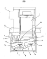
- FIG. 3 is a diagram illustrating wiping operation performed by a maintenance mechanism according to the embodiment of the present invention, in which designated by 6d is a claw push-down projecting part provided on a slide member 6 for forcing a claw member 7 downward in contact with the claw member 7.
- 6d is a claw push-down projecting part provided on a slide member 6 for forcing a claw member 7 downward in contact with the claw member 7.
- a lock-on claw 6c of the slide member 6 becomes engaged with the claw member 7, the slide member 6 is locked by a base member 5 (refer to FIG. 1 ) and a printhead of an ink cartridge 1 which moves with the carriage 2 slides relative to a wiper 4 which is set in a fixed state, whereby wiping operation (cleaning of an ink nozzle face) is performed.
- an unlocking protruding part 2a formed to jut out beyond the bottom of the carriage 2 goes into contact with an upper-left projecting part of the claw member 7, thereby causing the claw member 7 to swing counterclockwise.
- the lock-on claw 6c unlocks the claw member 7 and the slide member 6 is released from its locked state, whereby the slide member 6 is caused to return back to a specified position, the claw member 7 is caused to swing counterclockwise by the claw push-down projecting part 6d projectingly formed on the slide member 6, and the aforesaid upper-left projecting part descends down to a position where the upper-left projecting part does not interfere with the unlocking protruding part 2a of the carriage 2 (refer to FIG. 1(B) ).
- FIG. 4 is a diagram illustrating capping operation performed by the maintenance mechanism according to the embodiment of the present invention.
- the right end portion of the carriage 2 goes into contact with the slide member/carriage joint part 6b (not shown) of the slide member 6 due to a movement of the carriage 2 toward the right end as shown in FIG. 4 .
- the right end portion of the carriage 2 pushes in the slide member/carriage joint part 6b toward the right end and forces the slide member 6 upward up to an uppermost position, and the printhead (ink nozzle) of the ink cartridge 1 is capped by the cap 3.
- the cap 3 and the wiper 4 provided on the slide member 6 are at positions located below an upper end portion of the claw member 7 and a left end of the claw member 7 does not jut out beyond the right end of the carriage 2 as illustrated in FIG. 1(B) . Therefore, the print job performed in the printing area by back-and-forth movements of the carriage 2 along the main scanning direction is not hindered at all by the maintenance mechanism and it becomes possible to achieve a reduction in size of the apparatus in width direction.
- the claw member 7 pivotably supported by the carriage 2 simply makes swinging motion at the - specified position relative to the slide member 6 which moves obliquely to the left and right, and the claw member 7 does not move to the left and right at all.
- the claw member 7 and the wiper 4 it becomes possible to cause the claw member 7 and the wiper 4 to be positioned at a location immediately beneath a sheet if the position of (the upper end portion of) the claw member 7 during the printing process is set lower than a surface of the sheet. Specifically, as it becomes possible to cause the position of the wiper 4 and a sheet transport area to overlap, it is possible to achieve a further reduction in size of the apparatus in the width direction.
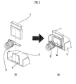
- FIG. 5 is a diagram illustrating a method of fixing a damper and a wiper to a slide member according to the embodiment of the present invention, in which FIG. 5(A) shows a state before the damper and the wiper are fixed to a fixing part of the slide member, and FIG. 5(B) shows a state in which the damper and the wiper have been fixed to the fixing part of the slide member.
- 6e is the fixing part of the slide member 6 to which the wiper 4 and the damper 12 are fixed to form a single structure.
- the damper 12 is structured with a compression spring having a shape which makes it possible to fix the damper 12 to the fixing part 6e.
- the wiper 4 has a shape which makes it possible to fix the wiper 4 after the damper 12 has been fixed to the fixing part 6e.
- the damper 12 may be fixed to the side of a metal frame 11 which faces the wiper 4.
- the maintenance mechanism of the present invention is not limited thereto but is similarly applicable to a multi-cartridge type printer in which a plurality of ink cartridges are mounted on a carriage.
Landscapes
- Ink Jet (AREA)
Applications Claiming Priority (5)
| Application Number | Priority Date | Filing Date | Title |
|---|---|---|---|
| JP2002294849 | 2002-10-08 | ||
| JP2002294849 | 2002-10-08 | ||
| JP2002372702A JP2004181919A (ja) | 2002-10-08 | 2002-12-24 | インクジェットプリンタのメンテナンス機構 |
| JP2002372702 | 2002-12-24 | ||
| PCT/JP2003/012861 WO2004033213A1 (ja) | 2002-10-08 | 2003-10-08 | インクジェットプリンタのメンテナンス機構 |
Publications (3)
| Publication Number | Publication Date |
|---|---|
| EP1555126A1 EP1555126A1 (en) | 2005-07-20 |
| EP1555126A4 EP1555126A4 (en) | 2009-09-23 |
| EP1555126B1 true EP1555126B1 (en) | 2010-12-22 |
Family
ID=32095405
Family Applications (1)
| Application Number | Title | Priority Date | Filing Date |
|---|---|---|---|
| EP03751374A Expired - Lifetime EP1555126B1 (en) | 2002-10-08 | 2003-10-08 | Maintenance mechanism for inkjet printer |
Country Status (6)
| Country | Link |
|---|---|
| US (1) | US7316466B2 (enExample) |
| EP (1) | EP1555126B1 (enExample) |
| JP (1) | JP2004181919A (enExample) |
| AU (1) | AU2003271121A1 (enExample) |
| DE (1) | DE60335482D1 (enExample) |
| WO (1) | WO2004033213A1 (enExample) |
Families Citing this family (22)
| Publication number | Priority date | Publication date | Assignee | Title |
|---|---|---|---|---|
| JP4920903B2 (ja) * | 2005-05-12 | 2012-04-18 | キヤノン株式会社 | インクジェット記録装置 |
| WO2008109536A1 (en) * | 2007-03-02 | 2008-09-12 | Marvell International Ltd. | Device and method for servicing an inkjet print head on a hand held printer |
| US7988256B2 (en) | 2008-08-28 | 2011-08-02 | Hewlett-Packard Development Company, L.P. | Web |
| US8118392B2 (en) | 2008-08-28 | 2012-02-21 | Hewlett-Packard Development Company, L.P. | Movable web support and cap |
| US8398205B2 (en) * | 2010-06-25 | 2013-03-19 | Hewlett-Packard Development Company, L.P. | Wiping device for inkjet printers |
| CN102248796B (zh) * | 2011-04-21 | 2013-08-28 | 北京美科艺数码科技发展有限公司 | 喷墨打印机用维护装置 |
| WO2015180792A1 (en) | 2014-05-30 | 2015-12-03 | Hewlett-Packard Development Company, L.P. | Wipe cartridge carriage |
| US9782971B2 (en) * | 2015-12-07 | 2017-10-10 | The Procter & Gamble Company | Cartridge servicing cases for fluid jet cartridge |
| US10166799B2 (en) | 2015-12-07 | 2019-01-01 | The Procter & Gamble Company | Service stations for handheld fluid jet apparatuses |
| US10391042B2 (en) | 2015-12-07 | 2019-08-27 | The Procter & Gamble Company | Treatment compositions, apparatus and methods for modifying keratinous surfaces |
| US11590782B2 (en) | 2015-12-07 | 2023-02-28 | The Procter & Gamble Company | Systems and methods for providing a service station routine |
| US11077689B2 (en) | 2015-12-07 | 2021-08-03 | The Procter & Gamble Company | Systems and methods for providing a service station routine |
| US10723120B2 (en) * | 2016-07-27 | 2020-07-28 | Goss International Americas, Inc. | Ink delivery system and method |
| US10849843B2 (en) | 2018-02-01 | 2020-12-01 | The Procter & Gamble Company | Stable cosmetic ink composition |
| US10610471B2 (en) | 2018-02-01 | 2020-04-07 | The Procter & Gamble Company | Cosmetic ink composition comprising a surface tension modifier |
| US10813857B2 (en) | 2018-02-01 | 2020-10-27 | The Procter & Gamble Company | Heterogenous cosmetic ink composition for inkjet printing applications |
| US10800174B2 (en) | 2019-02-11 | 2020-10-13 | Xerox Corporation | Evaporative ink-blocking film devices stabilizing ink in nozzles of inkjet printheads |
| US10814631B2 (en) | 2019-02-11 | 2020-10-27 | Xerox Corporation | Inkjet printhead cap having rotatable panels |
| US10710371B1 (en) * | 2019-02-11 | 2020-07-14 | Xerox Corporation | Inkjet printhead cap having latching system |
| US10894411B2 (en) | 2019-02-11 | 2021-01-19 | Xerox Corporation | Cap and application devices stabilizing ink in nozzles of inkjet printheads |
| US10696052B1 (en) | 2019-02-11 | 2020-06-30 | Xerox Corporation | Submersion cap devices stabilizing ink in nozzles of inkjet printheads |
| US10857798B2 (en) | 2019-02-11 | 2020-12-08 | Xerox Corporation | Cap and evaporative devices stabilizing ink in nozzles of inkjet printheads |
Family Cites Families (10)
| Publication number | Priority date | Publication date | Assignee | Title |
|---|---|---|---|---|
| JPH0596740A (ja) | 1991-10-09 | 1993-04-20 | Ricoh Co Ltd | インクジエツト記録装置 |
| KR0131090Y1 (ko) * | 1995-12-12 | 1999-03-30 | 김광호 | 잉크제트 프린터용 헤드의 서어비스스테이션 장치 |
| US6109726A (en) | 1996-03-09 | 2000-08-29 | Lee; Yong-Duk | Service station of ink-jet printer |
| KR200151934Y1 (ko) * | 1996-03-28 | 1999-07-15 | 윤종용 | 잉크젯프린터의 서어비스 스테이션장치 |
| JPH10193629A (ja) * | 1997-01-13 | 1998-07-28 | Funai Electric Co Ltd | インクジェット印字装置のヘッドクリーニング機構 |
| JP2000233517A (ja) * | 1999-02-16 | 2000-08-29 | Funai Electric Co Ltd | インクジェットプリンタのメンテナンス装置 |
| KR100368932B1 (ko) * | 2000-03-25 | 2003-01-24 | 삼성전자 주식회사 | 잉크젯프린터의 와이핑 장치 |
| TW504463B (en) * | 2000-04-28 | 2002-10-01 | Benq Corp | Inkjet head maintaining device for printing device |
| US6533388B2 (en) * | 2001-03-09 | 2003-03-18 | Hewlett-Packard Company | Service station for an inkjet printer |
| JP3803082B2 (ja) * | 2001-11-13 | 2006-08-02 | 三星電子株式会社 | インクジェットプリンターのメンテナンス装置 |
-
2002
- 2002-12-24 JP JP2002372702A patent/JP2004181919A/ja active Pending
-
2003
- 2003-10-08 US US10/530,525 patent/US7316466B2/en not_active Expired - Fee Related
- 2003-10-08 AU AU2003271121A patent/AU2003271121A1/en not_active Abandoned
- 2003-10-08 DE DE60335482T patent/DE60335482D1/de not_active Expired - Lifetime
- 2003-10-08 EP EP03751374A patent/EP1555126B1/en not_active Expired - Lifetime
- 2003-10-08 WO PCT/JP2003/012861 patent/WO2004033213A1/ja not_active Ceased
Also Published As
| Publication number | Publication date |
|---|---|
| US7316466B2 (en) | 2008-01-08 |
| EP1555126A4 (en) | 2009-09-23 |
| US20060164460A1 (en) | 2006-07-27 |
| AU2003271121A1 (en) | 2004-05-04 |
| JP2004181919A (ja) | 2004-07-02 |
| WO2004033213A1 (ja) | 2004-04-22 |
| EP1555126A1 (en) | 2005-07-20 |
| DE60335482D1 (enExample) | 2011-02-03 |
Similar Documents
| Publication | Publication Date | Title |
|---|---|---|
| EP1555126B1 (en) | Maintenance mechanism for inkjet printer | |
| US5847728A (en) | Service station device in inkjet printer head | |
| JP3966205B2 (ja) | プリンタのメンテナンス装置 | |
| EP2269831B1 (en) | Image forming device | |
| US7175253B2 (en) | Maintenance apparatus used with an inkjet printer | |
| JP2004001464A (ja) | 印字装置 | |
| EP0896881A2 (en) | Ink jet recording device | |
| JP3728963B2 (ja) | インクジェット式記録装置 | |
| JP3767568B2 (ja) | 画像形成装置 | |
| US7552994B2 (en) | Print-head maintenance device for use in an inkjet printer | |
| CN100335287C (zh) | 喷墨打印机的维护机构 | |
| US6315386B1 (en) | Ink jet maintenance station having acoustic dampening | |
| US7959256B2 (en) | Device for cleaning out residual ink | |
| JP5237043B2 (ja) | インクジェット印字装置 | |
| US9434170B1 (en) | Print device | |
| JP3870318B2 (ja) | インクジェット式画像形成装置 | |
| JP6671925B2 (ja) | 記録装置 | |
| JP2005205640A (ja) | インクジェット記録装置 | |
| JP2025104889A (ja) | インクジェットプリンタ | |
| KR100217998B1 (ko) | 잉크젯프린터의 잉크헤드 캡핑 장치 | |
| JP3669194B2 (ja) | インクジェット式記録装置 | |
| JP4920903B2 (ja) | インクジェット記録装置 | |
| KR19980032694U (ko) | 저소음 헤드-캡 장치 | |
| JPH08174853A (ja) | インクジェット記録装置用インク噴射ヘッド清掃装置 | |
| JP2007196389A (ja) | インクジェットプリンタ |
Legal Events
| Date | Code | Title | Description |
|---|---|---|---|
| PUAI | Public reference made under article 153(3) epc to a published international application that has entered the european phase |
Free format text: ORIGINAL CODE: 0009012 |
|
| 17P | Request for examination filed |
Effective date: 20050504 |
|
| AK | Designated contracting states |
Kind code of ref document: A1 Designated state(s): AT BE BG CH CY CZ DE DK EE ES FI FR GB GR HU IE IT LI LU MC NL PT RO SE SI SK TR |
|
| AX | Request for extension of the european patent |
Extension state: AL LT LV MK |
|
| DAX | Request for extension of the european patent (deleted) | ||
| RBV | Designated contracting states (corrected) |
Designated state(s): DE GB |
|
| A4 | Supplementary search report drawn up and despatched |
Effective date: 20090824 |
|
| 17Q | First examination report despatched |
Effective date: 20091207 |
|
| GRAP | Despatch of communication of intention to grant a patent |
Free format text: ORIGINAL CODE: EPIDOSNIGR1 |
|
| GRAS | Grant fee paid |
Free format text: ORIGINAL CODE: EPIDOSNIGR3 |
|
| GRAA | (expected) grant |
Free format text: ORIGINAL CODE: 0009210 |
|
| AK | Designated contracting states |
Kind code of ref document: B1 Designated state(s): DE GB |
|
| REG | Reference to a national code |
Ref country code: GB Ref legal event code: FG4D |
|
| REF | Corresponds to: |
Ref document number: 60335482 Country of ref document: DE Date of ref document: 20110203 Kind code of ref document: P |
|
| REG | Reference to a national code |
Ref country code: DE Ref legal event code: R096 Ref document number: 60335482 Country of ref document: DE Effective date: 20110203 |
|
| PLBE | No opposition filed within time limit |
Free format text: ORIGINAL CODE: 0009261 |
|
| STAA | Information on the status of an ep patent application or granted ep patent |
Free format text: STATUS: NO OPPOSITION FILED WITHIN TIME LIMIT |
|
| 26N | No opposition filed |
Effective date: 20110923 |
|
| REG | Reference to a national code |
Ref country code: DE Ref legal event code: R097 Ref document number: 60335482 Country of ref document: DE Effective date: 20110923 |
|
| PGFP | Annual fee paid to national office [announced via postgrant information from national office to epo] |
Ref country code: DE Payment date: 20131002 Year of fee payment: 11 Ref country code: GB Payment date: 20131002 Year of fee payment: 11 |
|
| REG | Reference to a national code |
Ref country code: DE Ref legal event code: R119 Ref document number: 60335482 Country of ref document: DE |
|
| GBPC | Gb: european patent ceased through non-payment of renewal fee |
Effective date: 20141008 |
|
| PG25 | Lapsed in a contracting state [announced via postgrant information from national office to epo] |
Ref country code: GB Free format text: LAPSE BECAUSE OF NON-PAYMENT OF DUE FEES Effective date: 20141008 Ref country code: DE Free format text: LAPSE BECAUSE OF NON-PAYMENT OF DUE FEES Effective date: 20150501 |