EP1554201B1 - Vorrichtung zur verteilung von teilen, insbesondere von nieten, die am ausgang eines speichers, z.b. eines schwingtopfes, abgegeben werden, sowie verfahren dafür - Google Patents
Vorrichtung zur verteilung von teilen, insbesondere von nieten, die am ausgang eines speichers, z.b. eines schwingtopfes, abgegeben werden, sowie verfahren dafür Download PDFInfo
- Publication number
- EP1554201B1 EP1554201B1 EP03778420A EP03778420A EP1554201B1 EP 1554201 B1 EP1554201 B1 EP 1554201B1 EP 03778420 A EP03778420 A EP 03778420A EP 03778420 A EP03778420 A EP 03778420A EP 1554201 B1 EP1554201 B1 EP 1554201B1
- Authority
- EP
- European Patent Office
- Prior art keywords
- conduit
- component
- fork
- components
- parts
- Prior art date
- Legal status (The legal status is an assumption and is not a legal conclusion. Google has not performed a legal analysis and makes no representation as to the accuracy of the status listed.)
- Expired - Lifetime
Links
- 238000011017 operating method Methods 0.000 title 1
- 238000000034 method Methods 0.000 claims abstract description 6
- 238000001514 detection method Methods 0.000 claims description 15
- 238000006073 displacement reaction Methods 0.000 claims description 6
- 230000000903 blocking effect Effects 0.000 claims description 3
- 238000012423 maintenance Methods 0.000 claims 3
- 238000000926 separation method Methods 0.000 claims 1
- 230000007306 turnover Effects 0.000 claims 1
- 238000011144 upstream manufacturing Methods 0.000 abstract description 5
- 239000012636 effector Substances 0.000 description 4
- 230000000694 effects Effects 0.000 description 3
- 241000287107 Passer Species 0.000 description 2
- 230000009471 action Effects 0.000 description 2
- 238000013461 design Methods 0.000 description 2
- 230000005484 gravity Effects 0.000 description 2
- 238000011160 research Methods 0.000 description 2
- 230000001133 acceleration Effects 0.000 description 1
- 230000006978 adaptation Effects 0.000 description 1
- 230000008901 benefit Effects 0.000 description 1
- 238000004891 communication Methods 0.000 description 1
- 230000007547 defect Effects 0.000 description 1
- 235000021183 entrée Nutrition 0.000 description 1
- 230000001747 exhibiting effect Effects 0.000 description 1
- 230000007246 mechanism Effects 0.000 description 1
- 238000012986 modification Methods 0.000 description 1
- 230000004048 modification Effects 0.000 description 1
- 238000005457 optimization Methods 0.000 description 1
- 238000004806 packaging method and process Methods 0.000 description 1
- 230000009897 systematic effect Effects 0.000 description 1
Images


Classifications
-
- B—PERFORMING OPERATIONS; TRANSPORTING
- B65—CONVEYING; PACKING; STORING; HANDLING THIN OR FILAMENTARY MATERIAL
- B65G—TRANSPORT OR STORAGE DEVICES, e.g. CONVEYORS FOR LOADING OR TIPPING, SHOP CONVEYOR SYSTEMS OR PNEUMATIC TUBE CONVEYORS
- B65G47/00—Article or material-handling devices associated with conveyors; Methods employing such devices
- B65G47/22—Devices influencing the relative position or the attitude of articles during transit by conveyors
- B65G47/24—Devices influencing the relative position or the attitude of articles during transit by conveyors orientating the articles
- B65G47/256—Devices influencing the relative position or the attitude of articles during transit by conveyors orientating the articles removing incorrectly orientated articles
-
- B—PERFORMING OPERATIONS; TRANSPORTING
- B21—MECHANICAL METAL-WORKING WITHOUT ESSENTIALLY REMOVING MATERIAL; PUNCHING METAL
- B21J—FORGING; HAMMERING; PRESSING METAL; RIVETING; FORGE FURNACES
- B21J15/00—Riveting
- B21J15/10—Riveting machines
- B21J15/30—Particular elements, e.g. supports; Suspension equipment specially adapted for portable riveters
- B21J15/32—Devices for inserting or holding rivets in position with or without feeding arrangements
-
- B—PERFORMING OPERATIONS; TRANSPORTING
- B23—MACHINE TOOLS; METAL-WORKING NOT OTHERWISE PROVIDED FOR
- B23P—METAL-WORKING NOT OTHERWISE PROVIDED FOR; COMBINED OPERATIONS; UNIVERSAL MACHINE TOOLS
- B23P19/00—Machines for simply fitting together or separating metal parts or objects, or metal and non-metal parts, whether or not involving some deformation; Tools or devices therefor so far as not provided for in other classes
- B23P19/001—Article feeders for assembling machines
- B23P19/002—Article feeders for assembling machines orientating the articles
-
- B—PERFORMING OPERATIONS; TRANSPORTING
- B23—MACHINE TOOLS; METAL-WORKING NOT OTHERWISE PROVIDED FOR
- B23P—METAL-WORKING NOT OTHERWISE PROVIDED FOR; COMBINED OPERATIONS; UNIVERSAL MACHINE TOOLS
- B23P19/00—Machines for simply fitting together or separating metal parts or objects, or metal and non-metal parts, whether or not involving some deformation; Tools or devices therefor so far as not provided for in other classes
- B23P19/001—Article feeders for assembling machines
- B23P19/004—Feeding the articles from hoppers to machines or dispensers
Definitions
- the present invention relates to the field of vibratory bowls and in particular adaptations to better manage the orientation and distribution of the pieces delivered at the output of storage and unit dispensing means such as vibrating bowls.
- This device has the advantage of using compressed air to avoid the use of gravity to supply the effectors and orient the parts for the effectors.
- This displacement of air also makes it possible to set in motion the pieces to be dispensed from the storage means, which is not a vibratory bowl, towards the dispensing means.
- the device ensures the distribution of parts including rivets delivered at the output of a storage means such as a vibrating bowl which has at its output a path of movement of said parts, a control module allowing entry one to one of the parts delivered by said storage and distribution means inside a pipe.
- a storage means such as a vibrating bowl which has at its output a path of movement of said parts
- this device is remarkable in that it consists of a module for controlling the orientation of each piece passing through the pipe and by a suction means intended to drive the parts already in motion, inside the pipe unitarily by acceleration of the most vulnerable part to the depression, the pipe being located in extension of the path of displacement.
- This feature is particularly advantageous in that it proposes a detection of the orientation of the parts after their exit from the vibratory bowl and before the passage in the device ensuring the phase following that of distribution.
- the taking of a reliable information makes it possible to direct the workpiece or the rivet directly towards the following phase in the orientation in which it has been introduced into the pipe or to be directed towards a turning device in order to ensure its reversal and present the orientation sought.
- the control of the passage of the parts makes it possible not to exceed the capacities of the means of control of the orientation.
- such a device can count the number of parts which it controls the orientation, which is a particularly interesting feature in the context of a step of intermediate packaging distributed parts.
- the movement of the parts inside the device is provided not by means of motorized movement but by the circulation of air and thus the depression of the pipe by the suction means.
- the choice of this means of setting in motion is particularly judicious in that it optimizes the unitary passage of the parts inside the device. Indeed, the suction will have effect only on the nearest piece of the pipe leaving in place the next much less subject to depression being further away and being hampered by the presence of a first part.
- the optimization of the airlock formed by the control module of the inlet of the pipe ensures a unitary passage of the parts at the control module and consequently a good detection of the orientation of said parts.
- the dispensing device of the invention differs from that proposed by the prior art, in that it is located at the outlet of a vibratory bowl or equivalent which, by definition, ensures the movement towards its output of the parts it stores.
- the parts that the device of the invention receives are already in motion.
- the purpose of the aspiration therefore is not to set the parts in motion but to accelerate the movement of the one at the exit end of the travel path to be covered and to guarantee a unitary entry into the dispensing device. -even subject to the vibrations of the bowl.
- the device for dispensing parts delivered at the outlet of a vibratory bowl therefore responds to other functions than those required for a device for dispensing parts stored in a more conventional means. It is the result of a constant concern of the applicants seeking to control the orientation of the parts as far upstream as possible from the displacement circuit of the latter, ie at the level of the storage means, which is, in this case, a vibrating medium.
- the suction used in the invention is therefore a means of accelerating the movement of certain parts already in motion, this aspiration ensuring that the part most subjected to the depression will be the first and therefore the only one to be introduced into the dispensing device of the invention.
- the device of the invention is attached to the vibratory bowl with which it is associated.
- the device judiciously uses the setting in motion of the parts conventionally performed by a vibratory bowl for bring the pieces to the entrance of the pipe.
- the invention also relates to the working method of such a device and the vibratory bowl adapted to such a device.
- This vibrating bowl having at its output a path of movement of said parts, is remarkable in that it is preformed to accommodate in a fixed manner, the device of the invention.
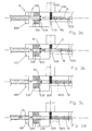
- the device for distributing parts with symmetry of revolution referenced D as a whole, in particular rivets referenced R, delivered at the output of a storage means such as a referenced vibratory bowl 100 which has at its output 110 a path of movement of said parts R, is constituted by a control module 200 allowing one-to-one input parts R delivered by said storage means 100 inside a pipe C and by a control module 300 of the orientation of each piece R passing through the pipe C.
- the device D is attached to the vibratory bowl 100 with which it is associated.
- the device D comprises an unillustrated suction means tending to drive the parts R inside the pipe C and to move it inside. Parts R follow the path illustrated by the arrows referenced F which are here parallel to the axis of the pipe C.
- the longitudinal axis of said pipe C is arranged coaxially with the axis of the parts R.
- the diameter of the pipe is defined so that the largest diameter of the symmetry pieces of revolution likely to be distributed in the bowl 100 can pass.
- said control module 200 is constituted by a first non-illustrated detection means and by a movable element 210 placed in front of the inlet of the pipe C and whose movement for closing the inlet of the pipe C is controlled by the detection by said first detection means of the inlet of a part R inside the pipe C.
- the parts R are under the effect of vibration of the vibrating bowl at the inlet of the pipe C which is subjected to a vacuum tending to suck the parts R.
- the implementation moving towards the device D is provided by the vibrations of the bowl and then inside the pipe unitarily due to the depression exerted by the suction means.
- control module 200 advantageously comprises a ramp 220 upstream of the inlet of the pipe C and coming in extension of the preformed displacement path in the vibrating bowl 100 at its output 110.
- control module 200 actuates the movable member 210 in the direction of the arrow A to obstruct the entry of the pipe C ensuring the unit passage of the parts R to the inside of the device D avoiding any risk of jamming or incorrect detection of the orientation of the part R.
- the movable element 210 for controlling the inlet of the pipe C is actuated by a cylinder-type setting mechanism 211, the mobile element 210 constituting the end of the same rod of this last (211).
- the axis of the rod of the cylinder 211 is perpendicular to the axis of the pipe C, the rod exit (arrow A) thus blocking the entry of the pipe C, the re-entry of the rod. releasing.
- said control module 300 is constituted by a second detection means 310 placed immediately beside a retractable means for holding in position 320 the part R introduced into line C, the absence or the presence a part of the part R on the side of the holding means in position 320 where the detection means 310 is located, thus giving the information concerning the orientation of the part R.
- connection 400 allowing the link with any means of routing distributed parts whose orientation has been detected.
- FIGS. 3a, 3b, 3c and 3d The operation of the device of the invention is illustrated in more detail by the drawings of FIGS. 3a, 3b, 3c and 3d.
- said position holding means 320 is constituted by a fork with two branches 330 coming from either side of the axis of the pipe C which they obstruct and whose spacing determines the diameter of the part likely to to move from the R part introduced into line C and abutting on the branches 330 of the fork.
- the holding fork in position 330 is actuated by a cylinder-type actuating means 331 (see FIG. 2).
- the rod outlet allows the legs of the fork 330 to obstruct the pipe C and the stem retraction allows to release the passage.
- the movable control element of the inlet of the pipe and the holding fork in position are each actuated by actuating means of cylinder type.
- Figure 4 illustrates an application to which the device is particularly adapted and useful.
- conventional rivets can be oriented for example by gravity due to the imbalance of mass and / or volume between their stem and their head, it is not the same with the blind rivets which have a rod of different diameter on either side of the head.
- the pull rod is the one with the smallest diameter.
- the spacing of the fork 330 is calculated so as to let the small diameter of the pull rod (as shown) and not to allow larger diameter.
- the fork 330 obstructing the pipe C if the detector 300 detects the presence of a rod, it directs the workpiece directly to the actuator performing the next step and not to the turning device.
- the detection module 310 does not detect the presence of a rod, it is because the pull rod is behind (relative to the direction of advance of the pieces R illustrated by the arrow F) requiring its switch towards the turning device.
- FIG. 1 also illustrates an embodiment of a vibratory bowl 100 according to the invention exhibiting its output level 110 a path of movement of said parts R and remarkable in that it is preformed to accommodate in a fixed manner, a device D constituted by a control module 200 allowing the entry one by one of the parts R delivered by said 100 inside a pipe C, by a control module 300 of the orientation of each piece R passing through the pipe C and by suction means tending to drive the pieces R inside the pipe C, the path of movement of said parts R being coaxial with said pipe C.
- a device D constituted by a control module 200 allowing the entry one by one of the parts R delivered by said 100 inside a pipe C, by a control module 300 of the orientation of each piece R passing through the pipe C and by suction means tending to drive the pieces R inside the pipe C, the path of movement of said parts R being coaxial with said pipe C.
- the device of the invention can be physically separated from the vibratory bowl while remaining simply connected by a supply duct parts.
- the device of the invention is sufficiently close to the output of the movement path of the vibratory bowl so that the suction can accelerate the movement of the first piece coming out and far enough that the vibrations of the vibratory bowl are not directly exerted on the dispensing device of the invention.
Landscapes
- Engineering & Computer Science (AREA)
- Mechanical Engineering (AREA)
- Feeding Of Articles To Conveyors (AREA)
- Automatic Assembly (AREA)
- Ultra Sonic Daignosis Equipment (AREA)
- Forging (AREA)
- Collating Specific Patterns (AREA)
Claims (8)
- Vorrichtung (D) zur Verteilung von Stücken (R) insbesondere Niete, die am Ausgang eines Lagermittels bereitgestellt werden, wie zum Beispiel einem Rüttler (100), der im Bereich seines Ausgangs (110)eine Verschiebungsstrecke der besagten Stücke (R) aufweist, wobei die Vorrichtung durch ein Steuermodul (200) gebildet wird, das den Eintritt der Stücke (R), die von dem besagten Lager- und Verteilungsmittel (100) bereitgestellt werden, nacheinander in eine Leitung (C)ermöglicht, DADURCH GEKENNZEICHNET, DASS SIE aus Folgendem besteht:- einem Kontrollmodul (300) zur Ausrichtung jedes Stücks (R), das durch die Leitung (C) verläuft und- einem Ansaugmittel, das zur Mitnahme der bereits in Bewegung befindlichen Stücke (R) in der Leitung (C) bestimmt ist und Stücks (R), das am meisten dem Unterdruck unterliegt, wobei sich die Leitung (C) in der Verlängerung der Verschiebungsstrecke befindet.
- Vorrichtung (D) gemäß Anspruch 1, DADURCH GEKENNZEICHNET, DASS die Längsachse der besagten Leitung (C) koaxial zur Achse der Stücke (R) angeordnet ist.
- Vorrichtung (D) gemäß Anspruch 1, DADURCH GEKENNZEICHNET, DASS das besagte Steuerungsmodul (200) aus einem ersten Erfassungsmittel und einem beweglichen Element (210) besteht, das sich vor dem Eingang der Leitung (C) befindet und dessen Inbewegungsetzung, die dazu dient, den Eingang der Leitung (C) zu schließen, durch die Erfassung durch das besagte erste Erfassungsmittel des Eingangs eines Stücks (R) in der Leitung (C) gesteuert wird.
- Vorrichtung (D) gemäß Anspruch 1, DADURCH GEKENNZEICHNET, DASS das besagte Kontrollmodul (300) aus einem zweiten Erfassungsmittel (310) besteht, das sich unmittelbar neben einem einziehbaren Mittel befindet, das dazu dient, das Stück (R) in Stellung zu halten, das in die Leitung (C) eingeführt wurde, wobei das Fehlen oder Vorhandensein eines Teils des Stücks (R) auf der Seite des Mittels zur Beibehaltung der Position (320), wo sich das Erfassungsmittel (310) befindet, das auf diese Weise die Information in Bezug auf die Ausrichtung des Stücks (R) gibt.
- Vorrichtung (D) gemäß Anspruch 4, DADURCH GEKENNZEICHNET, DASS das besagte Mittel zur Beibehaltung der Position (320) aus einer Gabel mit zwei Armen (330), die auf der einen und anderen Seite der Achse der Leitung (C) herauskommen, die sie blockieren und deren Abstand den Durchmesser des Teils festlegt, der durch das Stück (R) verlaufen kann, das in die Leitung (C) eingeführt wurde und auf den Armen (330) der Gabel anschlägt.
- Vorrichtung (D) gemäß Anspruch 3 und 5, DADURCH GEKENNZEICHNET, DASS das bewegliche Steuerungselement (210) des Eingangs der Leitung sowie die Gabel (330) zur Beibehaltung der Position jeweils durch Mittel zur Inbewegungsetzung, Typ Zylinder (211 und 331), angetrieben werden.
- Vorrichtung (D) gemäß Anspruch 1, deren Typ demjenigen entspricht, der mit einem Rüttler (100) verbunden ist, DADURCH GEKENNZEICHNET, DASS sie auf dem Rüttler (100) befestigt ist, mit dem sie verbunden ist.
- Arbeitsverfahren einer Vorrichtung (D) zur Verteilung von Stücken (R), insbesondere Niete, die durch ein Mittel zur Lagerung und Verteilung bereitgestellt werden, wie zum Beispiel ein Rüttler (100), gemäß der Zusammenfassung der gesamten Ansprüche 1 bis 6, die mit einem Mittel zur Umkehrung der Stücke (R) verbunden ist, das sich unter der Vorrichtung (D) befindet, DADURCH GEKENNZEICHNET, DASS das Verfahren mit dem laufenden Mittel zur Ansaugung und der Gabel (330), die die Leitung (C) blockiert, in Folgendem besteht:- Öffnen des Eingangs der Leitung (C) durch Entfernung des beweglichen Elementes (210),- Ermöglichen der Durchführung des abgesaugten Stücks (R1) ,- Schließen der Leitung (C) durch Rückführung des beweglichen Elementes (310), wenn die Durchführung des Stücks (R1) in der Leitung (C)erfasst wurde,- Erfassung des Vorhandenseins oder des Fehlens einer Stange unter der Gabel (330),- Einziehen der Gabel (330), um die Durchführung des Stücks (R1) zu ermöglichen,- Lenken oder nicht des Stücks (R1) in Richtung des Rückführungsmittels gemäß der gewünschten Ausrichtung der Teile und- Blockierung der Leitung (C) mit Hilfe der Gabel (330).
Applications Claiming Priority (3)
| Application Number | Priority Date | Filing Date | Title |
|---|---|---|---|
| FR0213346A FR2845978B1 (fr) | 2002-10-21 | 2002-10-21 | Dispositif de distribution de pieces, notamment de rivets, delivrees en sortie d'un moyen de stockage tel un bol vibrant, son procede de travail et bol vibrant adapte |
| FR0213346 | 2002-10-21 | ||
| PCT/FR2003/003113 WO2004037691A1 (fr) | 2002-10-21 | 2003-10-21 | Dispositif de distribution de pieces, notamment de rivets, delivrees en sortie d'un moyen de stockage tel un bol vibrant, son procede de travail et bol vibrant adapte |
Publications (2)
| Publication Number | Publication Date |
|---|---|
| EP1554201A1 EP1554201A1 (de) | 2005-07-20 |
| EP1554201B1 true EP1554201B1 (de) | 2007-02-21 |
Family
ID=32050670
Family Applications (1)
| Application Number | Title | Priority Date | Filing Date |
|---|---|---|---|
| EP03778420A Expired - Lifetime EP1554201B1 (de) | 2002-10-21 | 2003-10-21 | Vorrichtung zur verteilung von teilen, insbesondere von nieten, die am ausgang eines speichers, z.b. eines schwingtopfes, abgegeben werden, sowie verfahren dafür |
Country Status (8)
| Country | Link |
|---|---|
| US (1) | US20060037843A1 (de) |
| EP (1) | EP1554201B1 (de) |
| AT (1) | ATE354532T1 (de) |
| AU (1) | AU2003285420A1 (de) |
| DE (1) | DE60312020T2 (de) |
| ES (1) | ES2282699T3 (de) |
| FR (1) | FR2845978B1 (de) |
| WO (1) | WO2004037691A1 (de) |
Families Citing this family (6)
| Publication number | Priority date | Publication date | Assignee | Title |
|---|---|---|---|---|
| FR2870761B1 (fr) * | 2004-05-27 | 2007-08-10 | F2 C2 System Sa | Dispositif de distribution unitaire de pieces tels les rivets et procede mis en oeuvre |
| ES2385449B1 (es) * | 2010-12-28 | 2013-05-31 | Mondragón Goi Eskola Politeknikoa José María Arizmendiarrieta, S. Coop. | Dispositivo de posicionado de arandelas de retención |
| CN107717461A (zh) * | 2016-08-11 | 2018-02-23 | 昆山金群力精密组件有限公司 | 全自动的铆钉点焊设备 |
| ES2986828T3 (es) * | 2018-12-13 | 2024-11-12 | Howmet Aerospace Inc | Sistemas de recarga del dispensador de remaches y métodos de uso de los mismos |
| CN114933153B (zh) * | 2022-05-10 | 2024-05-28 | 广东恒翼能科技股份有限公司 | 分钉装置 |
| CN116532375B (zh) * | 2023-07-07 | 2023-09-19 | 杭州鄂达精密机电科技有限公司 | 一种工件视觉检测上料系统及全检机 |
Family Cites Families (26)
| Publication number | Priority date | Publication date | Assignee | Title |
|---|---|---|---|---|
| US3591047A (en) * | 1968-10-08 | 1971-07-06 | Continental Can Co | Cup bounce suppression by a vacuum |
| US3675302A (en) * | 1970-12-09 | 1972-07-11 | Paul H Dixon | Automatic assembly machine |
| US3757995A (en) * | 1971-05-20 | 1973-09-11 | Sperry Rand Corp | Small particle dispenser |
| US4006812A (en) * | 1972-12-29 | 1977-02-08 | Zapata Industries, Inc. | Automatic feeding hopper |
| US4278184A (en) * | 1979-08-27 | 1981-07-14 | Willis Clyde P | Escapement mechanism for automatic fastener insert mechanisms |
| US4363573A (en) * | 1980-10-30 | 1982-12-14 | Clyde Corporation | Article feeding apparatus |
| US4515260A (en) * | 1983-03-28 | 1985-05-07 | The Boeing Company | Escapement orienting mechanism |
| US4703868A (en) * | 1985-12-23 | 1987-11-03 | University Of Florida | Apparatus for metering and dispensing seeds |
| US4953749A (en) * | 1986-05-27 | 1990-09-04 | Nitto Kogyo Kabushiki Kaisha | Chip separation and alignment apparatus |
| US5385434A (en) * | 1992-12-09 | 1995-01-31 | Molex Incorporated | Electrical connector delivery system |
| US5913428A (en) * | 1995-02-16 | 1999-06-22 | Graham; S. Neal | Vibratory bowl and associated parts orienting tooling with pivotal top confinement |
| US5853108A (en) * | 1995-08-21 | 1998-12-29 | Matsushita Electric Industrial Co., Ltd. | Parts feed apparatus and parts feed method |
| JP3579234B2 (ja) * | 1997-12-09 | 2004-10-20 | 太陽誘電株式会社 | チップ部品供給装置 |
| US6119893A (en) * | 1998-05-07 | 2000-09-19 | Ismecam | Component advancement and extraction method and apparatus |
| US6116840A (en) * | 1998-08-21 | 2000-09-12 | Taiyo Yuden Co., Ltd. | Component supply apparatus |
| US6261030B1 (en) * | 1998-11-05 | 2001-07-17 | Omega Design Corp. | Desiccant feeder system and apparatus |
| JP3520008B2 (ja) * | 1999-12-24 | 2004-04-19 | 太陽誘電株式会社 | 電子部品供給装置 |
| US6662953B1 (en) * | 2000-05-01 | 2003-12-16 | James Allen Rouse | Air pulse feeder |
| JP3794902B2 (ja) * | 2000-06-05 | 2006-07-12 | 太陽誘電株式会社 | 電子部品供給装置 |
| DE20013365U1 (de) * | 2000-08-03 | 2000-11-30 | Avdel Verbindungselemente GmbH, 30851 Langenhagen | Vorrichtung zum Laden eines Nietmoduls mit Dornbruchblindnieten |
| US6533504B1 (en) * | 2000-11-10 | 2003-03-18 | David Tye | Bottle cap elevator |
| US6752291B2 (en) * | 2001-03-29 | 2004-06-22 | Taiyo Yuden Co., Ltd. | Component feeding method, component feeding apparatus, and component feeding unit |
| US6726057B2 (en) * | 2001-06-05 | 2004-04-27 | Fairchild Holding Corporation | Orienting ejector |
| US6877933B2 (en) * | 2001-09-20 | 2005-04-12 | Asm Technology Singapore Pte. Ltd. | Pellet feeding system for a molding machine |
| US6884016B2 (en) * | 2002-11-04 | 2005-04-26 | Kimberly-Clark Worldwide, Inc. | Positioning system for an automatic accumulation system |
| US7108155B2 (en) * | 2002-11-04 | 2006-09-19 | Kimberly-Clark Worldwide, Inc. | Metering drum for an automatic accumulation system |
-
2002
- 2002-10-21 FR FR0213346A patent/FR2845978B1/fr not_active Expired - Fee Related
-
2003
- 2003-10-21 DE DE60312020T patent/DE60312020T2/de not_active Expired - Lifetime
- 2003-10-21 AT AT03778420T patent/ATE354532T1/de not_active IP Right Cessation
- 2003-10-21 ES ES03778420T patent/ES2282699T3/es not_active Expired - Lifetime
- 2003-10-21 WO PCT/FR2003/003113 patent/WO2004037691A1/fr not_active Ceased
- 2003-10-21 EP EP03778420A patent/EP1554201B1/de not_active Expired - Lifetime
- 2003-10-21 AU AU2003285420A patent/AU2003285420A1/en not_active Abandoned
- 2003-10-21 US US10/532,184 patent/US20060037843A1/en not_active Abandoned
Also Published As
| Publication number | Publication date |
|---|---|
| ATE354532T1 (de) | 2007-03-15 |
| WO2004037691A1 (fr) | 2004-05-06 |
| AU2003285420A1 (en) | 2004-05-13 |
| EP1554201A1 (de) | 2005-07-20 |
| ES2282699T3 (es) | 2007-10-16 |
| FR2845978A1 (fr) | 2004-04-23 |
| DE60312020T2 (de) | 2007-11-15 |
| FR2845978B1 (fr) | 2005-07-22 |
| US20060037843A1 (en) | 2006-02-23 |
| DE60312020D1 (de) | 2007-04-05 |
Similar Documents
| Publication | Publication Date | Title |
|---|---|---|
| EP1921028B1 (de) | Zentrifugalvorrichtung zur Zuführung von liegenden und hintereinander aufgereihten Formteilen | |
| EP3194309B1 (de) | Vorrichtung zur übertragung von beweglichen teilen | |
| EP1554201B1 (de) | Vorrichtung zur verteilung von teilen, insbesondere von nieten, die am ausgang eines speichers, z.b. eines schwingtopfes, abgegeben werden, sowie verfahren dafür | |
| FR2587246A1 (fr) | Appareil automatique pour poser des pieces de fixation telles que des rivets | |
| FR2832654A1 (fr) | Dispositif pour le tri de colis par separation morphologique | |
| WO2020094958A1 (fr) | Installation de tri de pieces en defilement | |
| EP3818252A1 (de) | Turbomaschine für flugzeug mit einer vielzahl von variablen bypassventilen und steuerungsverfahren | |
| FR2549457A1 (fr) | Dispositif de recherche d'extremite de fil | |
| EP0532605B1 (de) | Vorrichtung zur auswahl und verteilung von teilen wie nieten | |
| EP1322534B1 (de) | Verfahren und vorrichtung zur regelung von abstand und geschwindigkeit von zufallsverteilt geführten objekten | |
| FR2914913A1 (fr) | Installation de delivrance d'objets, notamment pour pharmacie. | |
| WO2013164070A1 (fr) | Dispositif de freinage d'un element plat en forme de feuille et procede de nettoyage d'un tel dispositif | |
| EP0333596A1 (de) | Vorrichtung zum Stapeln von flachen Gegenständen, wie Briefe | |
| FR2889510A1 (fr) | Procede de groupage de caisses sur un convoyeur et dispositif pour sa mise en oeuvre | |
| FR2944001A1 (fr) | Installation de distribution de pieces. | |
| WO2013079852A1 (fr) | Dispositif pour le deplacement en continu de bouteilles de gaz en direction d'une machine de remplissage | |
| CH624595A5 (de) | ||
| EP3305692B1 (de) | Transfer von gegenständen | |
| FR2612630A1 (fr) | Dispositif de controle automatique de tiges a tete filetees ou non filetees telles que par exemple des vis | |
| FR2985720A1 (fr) | Dispositif et procede de formation de lots a partir d'objets alignes et accoles | |
| FR2896173A1 (fr) | Dispositif d'alimentation en elements de fixation de type rivets notamment pour machine de rivetage | |
| FR2522627A1 (fr) | Dispositif de transport pour objets a amener a une machine de manutention, en particulier a une machine a etiqueter | |
| FR2909430A1 (fr) | Dispositif de montage d'une courroie muni d'un systeme de fixation par billes | |
| EP0086127B1 (de) | Hydraulische Anlage zum Abbremsen und Verriegeln, sowie deren Verwednung in automatischen Geschützladevorrichtungen | |
| EP3050830A1 (de) | Packungeinheittransferverfahren und enstprechende vorrichtung |
Legal Events
| Date | Code | Title | Description |
|---|---|---|---|
| PUAI | Public reference made under article 153(3) epc to a published international application that has entered the european phase |
Free format text: ORIGINAL CODE: 0009012 |
|
| 17P | Request for examination filed |
Effective date: 20050506 |
|
| AK | Designated contracting states |
Kind code of ref document: A1 Designated state(s): AT BE BG CH CY CZ DE DK EE ES FI FR GB GR HU IE IT LI LU MC NL PT RO SE SI SK TR |
|
| AX | Request for extension of the european patent |
Extension state: AL LT LV MK |
|
| DAX | Request for extension of the european patent (deleted) | ||
| RTI1 | Title (correction) |
Free format text: DEVICE FOR DISPENSING PARTS, FOR EXAMPLE RIVETS, WHICH ARE DELIVERED AT THE OUTLET OF A STORAGE MEANS SUCH AS A VIBRATING BOWL, AND OPERATING METHOD THEREOF |
|
| GRAP | Despatch of communication of intention to grant a patent |
Free format text: ORIGINAL CODE: EPIDOSNIGR1 |
|
| GRAS | Grant fee paid |
Free format text: ORIGINAL CODE: EPIDOSNIGR3 |
|
| GRAA | (expected) grant |
Free format text: ORIGINAL CODE: 0009210 |
|
| AK | Designated contracting states |
Kind code of ref document: B1 Designated state(s): AT BE BG CH CY CZ DE DK EE ES FI FR GB GR HU IE IT LI LU MC NL PT RO SE SI SK TR |
|
| PG25 | Lapsed in a contracting state [announced via postgrant information from national office to epo] |
Ref country code: NL Free format text: LAPSE BECAUSE OF FAILURE TO SUBMIT A TRANSLATION OF THE DESCRIPTION OR TO PAY THE FEE WITHIN THE PRESCRIBED TIME-LIMIT Effective date: 20070221 Ref country code: AT Free format text: LAPSE BECAUSE OF FAILURE TO SUBMIT A TRANSLATION OF THE DESCRIPTION OR TO PAY THE FEE WITHIN THE PRESCRIBED TIME-LIMIT Effective date: 20070221 Ref country code: IE Free format text: LAPSE BECAUSE OF FAILURE TO SUBMIT A TRANSLATION OF THE DESCRIPTION OR TO PAY THE FEE WITHIN THE PRESCRIBED TIME-LIMIT Effective date: 20070221 Ref country code: FI Free format text: LAPSE BECAUSE OF FAILURE TO SUBMIT A TRANSLATION OF THE DESCRIPTION OR TO PAY THE FEE WITHIN THE PRESCRIBED TIME-LIMIT Effective date: 20070221 Ref country code: SI Free format text: LAPSE BECAUSE OF FAILURE TO SUBMIT A TRANSLATION OF THE DESCRIPTION OR TO PAY THE FEE WITHIN THE PRESCRIBED TIME-LIMIT Effective date: 20070221 Ref country code: DK Free format text: LAPSE BECAUSE OF FAILURE TO SUBMIT A TRANSLATION OF THE DESCRIPTION OR TO PAY THE FEE WITHIN THE PRESCRIBED TIME-LIMIT Effective date: 20070221 |
|
| REG | Reference to a national code |
Ref country code: GB Ref legal event code: FG4D Free format text: NOT ENGLISH |
|
| REG | Reference to a national code |
Ref country code: CH Ref legal event code: EP |
|
| REF | Corresponds to: |
Ref document number: 60312020 Country of ref document: DE Date of ref document: 20070405 Kind code of ref document: P |
|
| REG | Reference to a national code |
Ref country code: IE Ref legal event code: FG4D Free format text: LANGUAGE OF EP DOCUMENT: FRENCH |
|
| PG25 | Lapsed in a contracting state [announced via postgrant information from national office to epo] |
Ref country code: SE Free format text: LAPSE BECAUSE OF FAILURE TO SUBMIT A TRANSLATION OF THE DESCRIPTION OR TO PAY THE FEE WITHIN THE PRESCRIBED TIME-LIMIT Effective date: 20070521 |
|
| PG25 | Lapsed in a contracting state [announced via postgrant information from national office to epo] |
Ref country code: BG Free format text: LAPSE BECAUSE OF EXPIRATION OF PROTECTION Effective date: 20070522 |
|
| GBT | Gb: translation of ep patent filed (gb section 77(6)(a)/1977) |
Effective date: 20070607 |
|
| PG25 | Lapsed in a contracting state [announced via postgrant information from national office to epo] |
Ref country code: PT Free format text: LAPSE BECAUSE OF FAILURE TO SUBMIT A TRANSLATION OF THE DESCRIPTION OR TO PAY THE FEE WITHIN THE PRESCRIBED TIME-LIMIT Effective date: 20070723 |
|
| NLV1 | Nl: lapsed or annulled due to failure to fulfill the requirements of art. 29p and 29m of the patents act | ||
| REG | Reference to a national code |
Ref country code: IE Ref legal event code: FD4D |
|
| REG | Reference to a national code |
Ref country code: ES Ref legal event code: FG2A Ref document number: 2282699 Country of ref document: ES Kind code of ref document: T3 |
|
| PG25 | Lapsed in a contracting state [announced via postgrant information from national office to epo] |
Ref country code: SK Free format text: LAPSE BECAUSE OF FAILURE TO SUBMIT A TRANSLATION OF THE DESCRIPTION OR TO PAY THE FEE WITHIN THE PRESCRIBED TIME-LIMIT Effective date: 20070221 |
|
| PLBE | No opposition filed within time limit |
Free format text: ORIGINAL CODE: 0009261 |
|
| STAA | Information on the status of an ep patent application or granted ep patent |
Free format text: STATUS: NO OPPOSITION FILED WITHIN TIME LIMIT |
|
| PG25 | Lapsed in a contracting state [announced via postgrant information from national office to epo] |
Ref country code: RO Free format text: LAPSE BECAUSE OF FAILURE TO SUBMIT A TRANSLATION OF THE DESCRIPTION OR TO PAY THE FEE WITHIN THE PRESCRIBED TIME-LIMIT Effective date: 20070221 Ref country code: CZ Free format text: LAPSE BECAUSE OF FAILURE TO SUBMIT A TRANSLATION OF THE DESCRIPTION OR TO PAY THE FEE WITHIN THE PRESCRIBED TIME-LIMIT Effective date: 20070221 |
|
| 26N | No opposition filed |
Effective date: 20071122 |
|
| REG | Reference to a national code |
Ref country code: FR Ref legal event code: TQ Ref country code: FR Ref legal event code: CL Ref country code: FR Ref legal event code: AU |
|
| PG25 | Lapsed in a contracting state [announced via postgrant information from national office to epo] |
Ref country code: IT Free format text: LAPSE BECAUSE OF NON-PAYMENT OF DUE FEES Effective date: 20071021 Ref country code: GR Free format text: LAPSE BECAUSE OF FAILURE TO SUBMIT A TRANSLATION OF THE DESCRIPTION OR TO PAY THE FEE WITHIN THE PRESCRIBED TIME-LIMIT Effective date: 20070522 |
|
| PG25 | Lapsed in a contracting state [announced via postgrant information from national office to epo] |
Ref country code: MC Free format text: LAPSE BECAUSE OF NON-PAYMENT OF DUE FEES Effective date: 20071031 |
|
| REG | Reference to a national code |
Ref country code: CH Ref legal event code: PL |
|
| PG25 | Lapsed in a contracting state [announced via postgrant information from national office to epo] |
Ref country code: CH Free format text: LAPSE BECAUSE OF NON-PAYMENT OF DUE FEES Effective date: 20071031 Ref country code: LI Free format text: LAPSE BECAUSE OF NON-PAYMENT OF DUE FEES Effective date: 20071031 |
|
| PG25 | Lapsed in a contracting state [announced via postgrant information from national office to epo] |
Ref country code: EE Free format text: LAPSE BECAUSE OF FAILURE TO SUBMIT A TRANSLATION OF THE DESCRIPTION OR TO PAY THE FEE WITHIN THE PRESCRIBED TIME-LIMIT Effective date: 20070221 |
|
| PGRI | Patent reinstated in contracting state [announced from national office to epo] |
Ref country code: IT Effective date: 20081101 |
|
| PG25 | Lapsed in a contracting state [announced via postgrant information from national office to epo] |
Ref country code: CY Free format text: LAPSE BECAUSE OF FAILURE TO SUBMIT A TRANSLATION OF THE DESCRIPTION OR TO PAY THE FEE WITHIN THE PRESCRIBED TIME-LIMIT Effective date: 20070221 |
|
| PG25 | Lapsed in a contracting state [announced via postgrant information from national office to epo] |
Ref country code: LU Free format text: LAPSE BECAUSE OF NON-PAYMENT OF DUE FEES Effective date: 20071021 |
|
| PG25 | Lapsed in a contracting state [announced via postgrant information from national office to epo] |
Ref country code: HU Free format text: LAPSE BECAUSE OF FAILURE TO SUBMIT A TRANSLATION OF THE DESCRIPTION OR TO PAY THE FEE WITHIN THE PRESCRIBED TIME-LIMIT Effective date: 20070822 Ref country code: TR Free format text: LAPSE BECAUSE OF FAILURE TO SUBMIT A TRANSLATION OF THE DESCRIPTION OR TO PAY THE FEE WITHIN THE PRESCRIBED TIME-LIMIT Effective date: 20070221 |
|
| PGFP | Annual fee paid to national office [announced via postgrant information from national office to epo] |
Ref country code: GB Payment date: 20141015 Year of fee payment: 12 |
|
| PGFP | Annual fee paid to national office [announced via postgrant information from national office to epo] |
Ref country code: IT Payment date: 20141028 Year of fee payment: 12 |
|
| PGFP | Annual fee paid to national office [announced via postgrant information from national office to epo] |
Ref country code: BE Payment date: 20141024 Year of fee payment: 12 |
|
| REG | Reference to a national code |
Ref country code: FR Ref legal event code: PLFP Year of fee payment: 13 |
|
| GBPC | Gb: european patent ceased through non-payment of renewal fee |
Effective date: 20151021 |
|
| PG25 | Lapsed in a contracting state [announced via postgrant information from national office to epo] |
Ref country code: GB Free format text: LAPSE BECAUSE OF NON-PAYMENT OF DUE FEES Effective date: 20151021 Ref country code: IT Free format text: LAPSE BECAUSE OF NON-PAYMENT OF DUE FEES Effective date: 20151021 |
|
| REG | Reference to a national code |
Ref country code: FR Ref legal event code: PLFP Year of fee payment: 14 |
|
| PG25 | Lapsed in a contracting state [announced via postgrant information from national office to epo] |
Ref country code: BE Free format text: LAPSE BECAUSE OF NON-PAYMENT OF DUE FEES Effective date: 20151031 |
|
| REG | Reference to a national code |
Ref country code: FR Ref legal event code: PLFP Year of fee payment: 15 |
|
| REG | Reference to a national code |
Ref country code: FR Ref legal event code: PLFP Year of fee payment: 16 |
|
| PGFP | Annual fee paid to national office [announced via postgrant information from national office to epo] |
Ref country code: DE Payment date: 20201028 Year of fee payment: 18 |
|
| REG | Reference to a national code |
Ref country code: DE Ref legal event code: R119 Ref document number: 60312020 Country of ref document: DE |
|
| PG25 | Lapsed in a contracting state [announced via postgrant information from national office to epo] |
Ref country code: DE Free format text: LAPSE BECAUSE OF NON-PAYMENT OF DUE FEES Effective date: 20220503 |
|
| PGFP | Annual fee paid to national office [announced via postgrant information from national office to epo] |
Ref country code: FR Payment date: 20221025 Year of fee payment: 20 |
|
| PGFP | Annual fee paid to national office [announced via postgrant information from national office to epo] |
Ref country code: ES Payment date: 20221102 Year of fee payment: 20 |
|
| REG | Reference to a national code |
Ref country code: ES Ref legal event code: FD2A Effective date: 20231027 |
|
| PG25 | Lapsed in a contracting state [announced via postgrant information from national office to epo] |
Ref country code: ES Free format text: LAPSE BECAUSE OF EXPIRATION OF PROTECTION Effective date: 20231022 |
|
| PG25 | Lapsed in a contracting state [announced via postgrant information from national office to epo] |
Ref country code: ES Free format text: LAPSE BECAUSE OF EXPIRATION OF PROTECTION Effective date: 20231022 |