EP1554006B1 - Katheterballon mit vorteilhaftem kegeldesign - Google Patents
Katheterballon mit vorteilhaftem kegeldesign Download PDFInfo
- Publication number
- EP1554006B1 EP1554006B1 EP03808944A EP03808944A EP1554006B1 EP 1554006 B1 EP1554006 B1 EP 1554006B1 EP 03808944 A EP03808944 A EP 03808944A EP 03808944 A EP03808944 A EP 03808944A EP 1554006 B1 EP1554006 B1 EP 1554006B1
- Authority
- EP
- European Patent Office
- Prior art keywords
- balloon
- catheter
- section
- cone
- median section
- Prior art date
- Legal status (The legal status is an assumption and is not a legal conclusion. Google has not performed a legal analysis and makes no representation as to the accuracy of the status listed.)
- Revoked
Links
- 238000013461 design Methods 0.000 title abstract description 13
- 238000000034 method Methods 0.000 claims abstract description 28
- 239000000463 material Substances 0.000 claims description 23
- 239000012530 fluid Substances 0.000 claims description 5
- 238000004891 communication Methods 0.000 claims description 2
- 230000010339 dilation Effects 0.000 abstract description 4
- 210000001624 hip Anatomy 0.000 description 11
- 238000005259 measurement Methods 0.000 description 9
- -1 polyethylene Polymers 0.000 description 5
- 238000004132 cross linking Methods 0.000 description 4
- 230000000916 dilatatory effect Effects 0.000 description 4
- 210000003414 extremity Anatomy 0.000 description 4
- 239000004952 Polyamide Substances 0.000 description 3
- 238000002399 angioplasty Methods 0.000 description 3
- 210000001367 artery Anatomy 0.000 description 3
- 238000004519 manufacturing process Methods 0.000 description 3
- 229920002647 polyamide Polymers 0.000 description 3
- 229920000728 polyester Polymers 0.000 description 3
- 229920002635 polyurethane Polymers 0.000 description 3
- 239000004814 polyurethane Substances 0.000 description 3
- 239000004698 Polyethylene Substances 0.000 description 2
- 239000000853 adhesive Substances 0.000 description 2
- 230000001070 adhesive effect Effects 0.000 description 2
- 238000000576 coating method Methods 0.000 description 2
- 238000002788 crimping Methods 0.000 description 2
- 230000003902 lesion Effects 0.000 description 2
- 238000012986 modification Methods 0.000 description 2
- 230000004048 modification Effects 0.000 description 2
- 239000004417 polycarbonate Substances 0.000 description 2
- 229920000515 polycarbonate Polymers 0.000 description 2
- 229920000573 polyethylene Polymers 0.000 description 2
- XLYOFNOQVPJJNP-UHFFFAOYSA-N water Substances O XLYOFNOQVPJJNP-UHFFFAOYSA-N 0.000 description 2
- VGGSQFUCUMXWEO-UHFFFAOYSA-N Ethene Chemical compound C=C VGGSQFUCUMXWEO-UHFFFAOYSA-N 0.000 description 1
- 239000005977 Ethylene Substances 0.000 description 1
- RYECOJGRJDOGPP-UHFFFAOYSA-N Ethylurea Chemical compound CCNC(N)=O RYECOJGRJDOGPP-UHFFFAOYSA-N 0.000 description 1
- JHWNWJKBPDFINM-UHFFFAOYSA-N Laurolactam Chemical compound O=C1CCCCCCCCCCCN1 JHWNWJKBPDFINM-UHFFFAOYSA-N 0.000 description 1
- 229920000299 Nylon 12 Polymers 0.000 description 1
- 229920002614 Polyether block amide Polymers 0.000 description 1
- 239000004642 Polyimide Substances 0.000 description 1
- 239000004734 Polyphenylene sulfide Substances 0.000 description 1
- 239000004743 Polypropylene Substances 0.000 description 1
- RTAQQCXQSZGOHL-UHFFFAOYSA-N Titanium Chemical compound [Ti] RTAQQCXQSZGOHL-UHFFFAOYSA-N 0.000 description 1
- XECAHXYUAAWDEL-UHFFFAOYSA-N acrylonitrile butadiene styrene Chemical compound C=CC=C.C=CC#N.C=CC1=CC=CC=C1 XECAHXYUAAWDEL-UHFFFAOYSA-N 0.000 description 1
- 239000004676 acrylonitrile butadiene styrene Substances 0.000 description 1
- 229920000122 acrylonitrile butadiene styrene Polymers 0.000 description 1
- 210000003484 anatomy Anatomy 0.000 description 1
- 230000004323 axial length Effects 0.000 description 1
- 210000003445 biliary tract Anatomy 0.000 description 1
- 239000011248 coating agent Substances 0.000 description 1
- 238000007796 conventional method Methods 0.000 description 1
- 229920001577 copolymer Polymers 0.000 description 1
- 210000004351 coronary vessel Anatomy 0.000 description 1
- 230000001186 cumulative effect Effects 0.000 description 1
- 230000007423 decrease Effects 0.000 description 1
- 230000003247 decreasing effect Effects 0.000 description 1
- 230000002708 enhancing effect Effects 0.000 description 1
- 230000004927 fusion Effects 0.000 description 1
- 210000001035 gastrointestinal tract Anatomy 0.000 description 1
- 238000003780 insertion Methods 0.000 description 1
- 230000037431 insertion Effects 0.000 description 1
- 229920000554 ionomer Polymers 0.000 description 1
- 238000009940 knitting Methods 0.000 description 1
- 239000012528 membrane Substances 0.000 description 1
- 229910001092 metal group alloy Inorganic materials 0.000 description 1
- 239000000203 mixture Substances 0.000 description 1
- 238000000465 moulding Methods 0.000 description 1
- 229910001000 nickel titanium Inorganic materials 0.000 description 1
- 229910052758 niobium Inorganic materials 0.000 description 1
- 239000010955 niobium Substances 0.000 description 1
- GUCVJGMIXFAOAE-UHFFFAOYSA-N niobium atom Chemical compound [Nb] GUCVJGMIXFAOAE-UHFFFAOYSA-N 0.000 description 1
- 230000002093 peripheral effect Effects 0.000 description 1
- 239000004033 plastic Substances 0.000 description 1
- 229920003023 plastic Polymers 0.000 description 1
- 229920001721 polyimide Polymers 0.000 description 1
- 229920000069 polyphenylene sulfide Polymers 0.000 description 1
- 229920001155 polypropylene Polymers 0.000 description 1
- 239000004800 polyvinyl chloride Substances 0.000 description 1
- 229920000915 polyvinyl chloride Polymers 0.000 description 1
- 230000008569 process Effects 0.000 description 1
- 238000009877 rendering Methods 0.000 description 1
- 230000001850 reproductive effect Effects 0.000 description 1
- 210000005000 reproductive tract Anatomy 0.000 description 1
- 230000000241 respiratory effect Effects 0.000 description 1
- 210000002345 respiratory system Anatomy 0.000 description 1
- 230000004044 response Effects 0.000 description 1
- 239000010935 stainless steel Substances 0.000 description 1
- 229910001220 stainless steel Inorganic materials 0.000 description 1
- 239000000126 substance Substances 0.000 description 1
- 229910052715 tantalum Inorganic materials 0.000 description 1
- GUVRBAGPIYLISA-UHFFFAOYSA-N tantalum atom Chemical compound [Ta] GUVRBAGPIYLISA-UHFFFAOYSA-N 0.000 description 1
- 230000001225 therapeutic effect Effects 0.000 description 1
- 238000007669 thermal treatment Methods 0.000 description 1
- 229920001169 thermoplastic Polymers 0.000 description 1
- 229920002725 thermoplastic elastomer Polymers 0.000 description 1
- 229920006259 thermoplastic polyimide Polymers 0.000 description 1
- 239000010936 titanium Substances 0.000 description 1
- 229910052719 titanium Inorganic materials 0.000 description 1
- 238000012546 transfer Methods 0.000 description 1
- 230000002485 urinary effect Effects 0.000 description 1
- 210000001635 urinary tract Anatomy 0.000 description 1
- 230000002792 vascular Effects 0.000 description 1
- 210000003462 vein Anatomy 0.000 description 1
- 230000009278 visceral effect Effects 0.000 description 1
- 238000005303 weighing Methods 0.000 description 1
Images



Classifications
-
- A—HUMAN NECESSITIES
- A61—MEDICAL OR VETERINARY SCIENCE; HYGIENE
- A61M—DEVICES FOR INTRODUCING MEDIA INTO, OR ONTO, THE BODY; DEVICES FOR TRANSDUCING BODY MEDIA OR FOR TAKING MEDIA FROM THE BODY; DEVICES FOR PRODUCING OR ENDING SLEEP OR STUPOR
- A61M25/00—Catheters; Hollow probes
- A61M25/10—Balloon catheters
- A61M25/1002—Balloon catheters characterised by balloon shape
-
- A—HUMAN NECESSITIES
- A61—MEDICAL OR VETERINARY SCIENCE; HYGIENE
- A61F—FILTERS IMPLANTABLE INTO BLOOD VESSELS; PROSTHESES; DEVICES PROVIDING PATENCY TO, OR PREVENTING COLLAPSING OF, TUBULAR STRUCTURES OF THE BODY, e.g. STENTS; ORTHOPAEDIC, NURSING OR CONTRACEPTIVE DEVICES; FOMENTATION; TREATMENT OR PROTECTION OF EYES OR EARS; BANDAGES, DRESSINGS OR ABSORBENT PADS; FIRST-AID KITS
- A61F2/00—Filters implantable into blood vessels; Prostheses, i.e. artificial substitutes or replacements for parts of the body; Appliances for connecting them with the body; Devices providing patency to, or preventing collapsing of, tubular structures of the body, e.g. stents
- A61F2/95—Instruments specially adapted for placement or removal of stents or stent-grafts
- A61F2/958—Inflatable balloons for placing stents or stent-grafts
-
- A—HUMAN NECESSITIES
- A61—MEDICAL OR VETERINARY SCIENCE; HYGIENE
- A61F—FILTERS IMPLANTABLE INTO BLOOD VESSELS; PROSTHESES; DEVICES PROVIDING PATENCY TO, OR PREVENTING COLLAPSING OF, TUBULAR STRUCTURES OF THE BODY, e.g. STENTS; ORTHOPAEDIC, NURSING OR CONTRACEPTIVE DEVICES; FOMENTATION; TREATMENT OR PROTECTION OF EYES OR EARS; BANDAGES, DRESSINGS OR ABSORBENT PADS; FIRST-AID KITS
- A61F2/00—Filters implantable into blood vessels; Prostheses, i.e. artificial substitutes or replacements for parts of the body; Appliances for connecting them with the body; Devices providing patency to, or preventing collapsing of, tubular structures of the body, e.g. stents
- A61F2/95—Instruments specially adapted for placement or removal of stents or stent-grafts
- A61F2/958—Inflatable balloons for placing stents or stent-grafts
- A61F2002/9583—Means for holding the stent on the balloon, e.g. using protrusions, adhesives or an outer sleeve
Definitions
- the present invention pertains generally to catheter balloons useful in medical dilation and stent delivery procedures as disclosed in the US6409741 . More specifically, the present invention relates to catheter balloons wherein the cone sections have a design that, in some applications, can provide the cone sections with the ability to preferentially inflate relative to the median section of the catheter balloon.
- Angioplasty is a widely utilized therapeutic treatment in which obstructed intraluminal passages are reopened or dilated.
- a catheter comprising an inflatable member, such as a balloon, is inserted percutaneously into a luminal passage of a patient, such as an artery, vein, airway, etc.
- the balloon is advanced to the desired treatment site, where the balloon may be inflated to dilate the luminal passage.
- the balloon catheter may be used to place an intravascular prosthesis, such as a stent, within the luminal passage, which prosthesis could then operate to maintain the patency of the luminal passage.
- vascular angioplasty and stenting are widely utilized and largely successful procedures, improvements to the same could yet be made.
- dilation procedures for example, it would be desirable for the inflatable member to controllably inflate, and at times preferentially inflate, to better control the position of the inflatable member.
- an intravascular prosthesis In procedures wherein an intravascular prosthesis is to be delivered, it would be desirable to enhance the robustness of the delivery of the prosthetic device.
- the invention is generally directed to catheter balloons including cone sections having an advantageous design.
- the cone sections have a ratio of the volume of one cone section to the transverse cross-sectional area of the fully inflated median section that can provide for a more controlled inflation of the balloon.
- this cone configuration can assist in the preferential expansion of the cones prior to the median section of the balloon.
- Such a preferential expansion can further act to control the position of the implantable device.
- the utilization of the inventive balloon can be particularly advantageous.
- the preferential expansion of the cone sections of the inventive balloon prior to the median section can aid in the release of the stent from such socks or sleeves.
- the invention provides a catheter balloon, and a method of forming the inventive catheter balloon.
- the catheter balloon generally has expandable cone sections proximal and distal to a median section of the balloon.
- the median section When the balloon is fully inflated, the median section has a transverse cross sectional area, and each cone section has a volume, so that the ratio of the volume, in mm 3 , of either of the cone sections to the transverse cross sectional area, in mm 2 , of the median section is at least about 2.1mm.
- this ratio and the measurements utilized in calculating the ratio, is/are expressed in millimeters, the measurements can be taken in any units and the ratio calculated, so long as the measurements or the resulting ratio are converted to the units of millimeters by applying the appropriate conversion factor.
- the invention provides a catheter balloon having cone sections proximal and distal to a median section of the balloon. At least one of the cone sections has a stepped configuration comprising a plurality of sections, wherein at least one of the sections defines an internal angle relative to the median section of greater than about 180 degrees.
- the invention provides a balloon catheter and method of manufacturing the same.
- the balloon catheter generally comprises a catheter having an elongated shaft with an inflatable catheter balloon on a distal section of the catheter shaft.
- the catheter balloon generally has expandable cone sections proximal and distal to a median section of the balloon. When the balloon is fully inflated, the median section has a transverse cross sectional area in mm 2 , and each cone section has a volume, in mm 3 , so that the ratio of the volume of either of the cone sections to the transverse cross sectional area of the median section is at least about 2.1mm.
- a further aspect of the invention provides a stent delivery system, the stent delivery system generally comprising a balloon catheter wherein the balloon catheter has an elongated shaft with an inflatable balloon on a distal section of the catheter shaft.
- the catheter balloon generally has expandable cone sections proximal and distal to a median section of the balloon. When the balloon is fully inflated, the median section has a transverse cross sectional area in mm 2 , and each cone section has a volume in mm 3 , so that the ratio of the volume of either of the cone sections to the transverse cross sectional area of the median section is at least about 2.1mm.
- An expandable stent is operatively disposed about at least a portion of the median section of the catheter balloon.
- the catheter balloon of the present invention can aid in the retraction of sleeves or socks in stent delivery systems including such sleeves or socks.
- the stent delivery system may further comprise at least one such sleeve or sock.
- the sleeve can be provided having a first end mounted on the distal shaft section distal to the catheter balloon and a second end defining a margin between the stent and the sleeve, wherein the sleeve overlies the margin between the stent and the median section when the catheter balloon is substantially uninflated.
- inventive catheter balloon when utilized as a component of an angioplasty catheter or a stent delivery system can provide for the improved performance thereof.
- inventive cone design When used in combination with a stent delivery system, for example, the inventive cone design can assist in the preferential expansion of the cone sections. This preferential expansion can reduce any shifting of the stent during delivery that may otherwise occur.
- the present invention additionally provides methods of dilating a bodily lumen, or for delivering a stent.
- the methods comprise the steps of providing a balloon catheter or stent delivery system embodying features of the present invention, inserting the balloon catheter, or stent delivery system, as the case may be, into a bodily lumen and inflating the balloon so that the median section expands to dilate the bodily lumen and/or to deliver the stent.
- the present invention provides balloons suitable for use in catheters comprising cone sections having an advantageous design.
- the inventive catheter balloon has cone sections having a volume so that the ratio of the volume of one cone (in mm 3 ) to the transverse cross sectional area of the fully inflated median section (in mm 2 ) is at least about 2.1mm.
- this ratio and the measurements utilized in calculating the ratio, is/are expressed in millimeters, the measurements can be taken in any units and the ratio calculated, so long as the measurements or the resulting ratio are converted to the units of millimeters by applying the appropriate conversion factor.
- catheter balloons having such cone sections can be more controllably inflated, and in certain applications, can provide preferential expansion of the cone sections prior to any significant expansion of the median section of the balloon.
- Balloons having such a cone design can be utilized in balloon catheters or prosthesis delivery systems where this capability can act to reduce any shifting of the prosthesis during expansion and delivery thereof that may otherwise occur.
- Figure 1 illustrates, in cross-sectional side view, an expanded inflatable balloon 10.
- Inflatable balloon 10 is described, for purposes of illustrating the design features of the invention, as having at least three regions.
- a first region is the centermost section, or the median section 12 of balloon 10, and is indicated by 'B' in Figure 1 .
- Median section 12 when inflated, runs generally parallel with, and engages, a patient's luminal passage, such as a vessel wall, or inner diameter of a stent.
- Median section 12 can comprise the majority of the length of inflatable balloon 10, and typically has the greatest diameter of the three regions when balloon 10 is fully inflated.
- Second regions of balloon 10 are comprised of the waists 16 on the first and second ends of balloon 10. Waists 16 are used to adhere balloon 10 to one or a more catheter shafts (not shown). Waists 16 are indicated by 'C' in Figure 1 .
- Third regions are comprised of the cone sections 14 of balloon 10 provided between the median section 12 and the waists 16.
- inflatable balloon 10 includes a single median section 12, proximal and distal cone sections 14 and proximal and distal waists 16.
- other configurations are possible and are within the scope of the present invention.
- other regions can be provided between the described sections 12, 14 and 16 to perform other functions.
- Cone sections 14 include a first section 20, defined by lines 3-3 and 4-4, a second section 22, defined by lines 2-2 and 3-3, and a third section 24, defined by lines 1-1 and 2-2.
- First section 20 is proximal to median section 12, and forms a first angle ⁇ relative to median section 12.
- First angle ⁇ is desirably between about 90° and about 180°.
- Second section 22 is proximal to first section 20 and forms an angle ⁇ relative to first section 20 as shown.
- Angle ⁇ is desirably between about 180° and 360°, typically between about 180° and 270°.
- Third section 24 is proximal to second section 22 and forms an angle ⁇ relative to second section 22 that is desirably between about 30° and 180°.
- a catheter balloon 10 can be produced that can provide a more controllable inflation that balloons not having the preselected ratio. More particularly, it has now been discovered that when the ratio of the volume of one cone section 14 (in mm 3 ) to the transverse cross-sectional area of the fully inflated median section 12 (in mm 2 ) is at least about 2.1mm, preferably at least about 2.25mm, more preferably, at least about 2.5mm, the advantages of the present invention can be seen.
- volume and transverse cross-sectional area measurements can be taken, and the ratio of the same calculated, in any units, so long as the units of either both of the measurements, or the calculated ratio, are mathematically converted to millimeters via application of the appropriate conversion factor.
- the ratio can be, for example, 3.0mm, 3.5mm, 4.0mm, 4.5mm, 5.0mm, etc.
- the inventive relationship is particularly advantageous when the ratio of the volume of one cone section 14 (in mm 3 ) to the transverse cross sectional area of fully inflated median section 12 (in mm 2 ) is from about 2.1mm to about 4.0mm, more preferably from about 2.1mm to about 2.5mm.
- the volume and/or shape of cone sections 14 on either side of median section 12 need not be identical, so long as the specified ratio can be achieved utilizing the volume of at least one cone section. That is, although the embodiment illustrated in Figure 1 of balloon 10 is symmetrical and median section 12 is at a central location on the balloon, alternative balloon designs may be used for particular applications and anatomies. Additionally, the inventive concept can be applied to any size catheter balloon 10, so long as the advantageous ratio of the volume of one cone section 14 to the transverse cross sectional area of the median section 12 is provided.
- cone sections 14 shape or geometry of cone sections 14 is not critical, and although a stepped cone configuration is illustrated in Figure 1 , cone sections 14 need not exhibit this configuration. Rather, cone sections 14 can be stepped, tapered or any other suitable configuration, as long as the ratio of the volume of one cone section 14 (in mm 3 ) to the transverse cross sectional area of fully inflated median section 12 (in mm 2 ) is at least about 2.1mm.
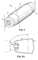
- Figure 2 shows a balloon catheter wherein the balloon includes 'bulged' cone sections 14 in addition to waists 16 and median section 12.
- waists 16 are indicated by 'C' in Figure 2A .
- Cone sections 14 are indicated by 'A' in Figure 2A and are provided between median section 12 and waists 16.
- cone volume would be calculated using the same formula as above, applied to two areas defined by the intervening angle(s). That is, the cone volume of the cone defined by lines 1-1 and 2-2, by lines 2-2 and 3-3 and by lines 3-3 and 4-4 would be calculated and added together to obtain the volume of one cone section 14 of balloon 10.
- the volume of cone sections 14 can be further easily determined by filling cone sections 14 with water, and weighing the water.
- transverse cross sectional area and cone volume are calculated as indicated above, regardless of any other parts and/or substances that may be introduced into the cone sections 14 or median section 12 once the balloon has been formed. That is, if catheter balloon 10 is to be included on a balloon catheter, as shown in Figure 2 , the volume of cone sections 14, or transverse cross-sectional area of median section 12, would be calculated without reducing the calculated volume or cross sectional area by that volume or cross sectional area that is taken up by, e.g., an inner tubular member and an outer tubular member, not shown in Figure 2 once the balloon catheter has been assembled. Further, the wall thickness of the balloon is assumed to be negligible, i.e., the calculations of cross-sectional area and volume that were performed were based upon the outer diameter of the respective balloon sections.
- the catheter balloon of the present invention can be produced by any suitable technique, including conventional techniques for producing catheter balloons.
- a catheter balloon embodying features of the present invention can be formed by molding.
- an extruded polymeric tube can be radially expanded and axially expanded within a mold generally having the desired shape of the balloon at elevated temperatures.
- the resulting balloon may be heat treated one or more times as is conventionally known, e.g., to reduce shrinkage of the balloon.
- Non-limiting examples of methods for manufacturing balloons are disclosed in U.S. Patent Nos. 4,950,239 ; 4,490,421 ; 5,195,969 ; 5,556,383 ; 6,210,364 ; 5,270,086 ; and 6,168,748 .
- Catheter balloon 10 may be formed from any material, or combination of materials, typically used to form catheter balloons.
- the particular material(s) chosen will depend upon the intended use of the catheter balloon.
- low pressure, relatively soft or flexible polymeric materials such a thermoplastic polymers, thermoplastic elastomers, polyethylene (high density, low density, intermediate density, linear low density), various copolymers and blends of polyethylene, ionomers, polyesters, polyurethanes and polyurethane copolymers (such as, e.g., Pellethane ® ), polycarbonates, polyamides (such as, e.g., Nylon 12), poly-vinyl chloride, acrylonitrile-butadiene-styrene copolymers, polyether-polyester copolymers (such as, e.g., Hytrel ® and Amitel ® ), and polyether-polyamide copolymers (such as, e.g.,
- materials having relatively rigid properties such as poly(ethylene terphthalate), polyimide, thermoplastic polyimide, polyamides, polyesters, polycarbonates, polyphenylene sulfides, polypropylene and rigid polyurethanes are useful.
- catheter balloon 10 may be comprised of a combination of materials, and may be coextruded, single layered or multilayered.
- Catheter balloon 10 may further be coated with any known suitable coating, if desired. Such coatings may be desirable, for example, in those applications where a lubricious balloon surface is desired.
- the balloon material may further be crosslinked or uncrosslinked, depending upon the nature of the material and the characteristics desired for a particular application.
- crosslinking a balloon material can result in greater control over the final inflated balloon size. That is, after crosslinking, initial pressurization, expansion, and preshrinking, a balloon so treated may thereafter expand in a more controlled manner to a reproducible diameter in response to a given inflation pressure, relative to an uncrosslinked balloon comprising similar material.
- crosslinking can be performed by any conventional crosslinking process, such as, for example, thermal treatment and/or E-beam exposure.
- any portion of balloon wall 18, shown in Figure 1 may be varied if desired. Varied balloon thickness can be useful, for example, in order to facilitate folding of balloon 10 around a catheter shaft to achieve a desired low profile, or to achieve various balloon pressure ratings. Material may be added, removed or combinations thereof to achieve the desired result.
- varying the thickness of balloon wall 18 is desired in median section 12 and/or cone sections 14 of balloon 10. Exemplary means of modifying the thickness of the cone sections of a balloon are disclosed in commonly assigned U.S. Patent No. 5,733,301 , the entirety of which is hereby incorporated by reference herein for all purposes.
- FIG. 3 illustrates a balloon catheter embodying features and advantages of the invention.
- Balloon catheter 300 generally includes an elongated catheter shaft 301 having proximal section 302 and distal section 303, an inflatable balloon 30 disposed on the distal section 303 of catheter shaft 301, and manifold 304 mounted on proximal section 302 of shaft 301 to permit controllable sliding over guidewire 311 and for fluid introduction within shaft 301.
- Radiopaque markers 314 may be provided on catheter shaft 301, as for example, on inner tubular member 307 near the proximal and distal ends of median section 32 of balloon 30.
- balloon catheter 300 is illustrated within a patient's body lumen 305 prior to expansion of balloon 30, i.e., with balloon 30 in a low profile, unexpanded state for advancement within the patient.
- catheter shaft 301 has an outer tubular member 306 and an inner tubular member 307 disposed within outer tubular member 306, and defining along with outer tubular member 306, inflation lumen 308.
- Inflation lumen 308 is in fluid communication with the interior chamber 309 of inflatable balloon 30.
- Inner tubular member 307 has an inner lumen 310 extending therethrough to slidably receive a guidewire 311 suitable for advancement through a patient's body lumen 305.
- the distal extremity of inflatable balloon 30 is sealingly secured to the distal extremity of inner tubular member 307 and the proximal extremity of the balloon 30 is sealingly secured to the distal extremity of the outer tubular member 306.
- Balloon 30 can be inflated by any fluid, e.g., radiopaque, injected through inflation port 312, or otherwise provided through inflation lumen 308, or by other means, such as from a passageway formed between the outside of the catheter shaft and the member forming balloon 30, depending on the particular design of the catheter.
- any fluid e.g., radiopaque
- inflation port 312 or otherwise provided through inflation lumen 308, or by other means, such as from a passageway formed between the outside of the catheter shaft and the member forming balloon 30, depending on the particular design of the catheter.
- the details and mechanics of fluid transfer and introduction within balloons vary according to the specific design of the catheter, and are well know in the art.
- balloon catheters are well known in the art, and all of these and other developed balloon catheters may incorporate the balloon features of the present invention. Examples include over-the-wire catheters, single operator or rapid exchange catheters, and fixed-wire catheters, to name a few.
- catheter shaft 301, and the outer tubular member 306 and inner tubular member 307 incorporated therein, can have the dimensions of any conventional dilatation or stent delivery catheters, and inner and outer tubular members incorporated into the same.
- Shaft diameters of conventional catheter shafts generally range e.g., from about 4 to about 15 French.
- Figures 4 and 5 illustrate the advantages that can be seen incorporating the inventive balloon 30 into balloon catheter 300 and then utilizing balloon catheter 300 in a treatment procedure.
- Figure 4 shows inflatable balloon 30 placed within lesion 38 located within a bodily lumen 305 and partially inflated.
- Figure 5 shows inflatable balloon 30 fully inflated so as to be dilating lesion 38 within bodily lumen 305.
- balloon 30 includes median section 32 centrally located on balloon 30 and cone sections 34 adjacent to the proximal and distal ends of median section 32. As shown, cone sections 34 taper or curve to join waists 36, but may be of any other geometry. Waist 36 of balloon 30 distal to median section 32 is sealingly secured to inner tubular member 307 while waist 36 of balloon 30 proximal to median section 32 is sealingly secured to outer tubular member 306, using any suitable means, such as adhesive and/or fusion bonding.
- FIG. 6-8 there is illustrated a stent delivery system 600 embodying features of the invention.
- the stent delivery system illustrated can be largely identical to the balloon catheter discussed above in connection with Figure 2 , and like features and the relationships between features will not be discussed further, as a description thereof can be found hereinabove.
- balloon 60 has stent 613 mounted thereon in order to form stent delivery system 600.
- Stent delivery system 600 is illustrated within a patient's body lumen 605, prior to expansion of balloon 60, with balloon 60 and stent 613 in a low profile, unexpanded state for advancement within the patient.
- Figure 7 shows balloon 60 partially inflated at a first, low pressure. Partial inflation of balloon 60 causes the inflation of cone sections 64, without causing significant expansion of median section 62, or stent 613 mounted on median section 62. When so partially inflated, median section 62 remains in a deflated, low profile configuration, while cone sections 64 have expanded to an inflated outer diameter greater than that of the outer diameter of median section 62 and stent 613.
- Stent 613 may be mounted onto balloon 60 by any known method, e.g., by causing stent 613 to contract, by folding or wrapping stent 613 around and onto balloon 60, by crimping stent 613 onto balloon 60, either by hand or with a crimping tool, or by any other known method.
- Stent 613 may also be formed of non-knitted material so that the axial length of stent 613 decreases as stent 613 expands, thus enhancing the release of stent 613 from stent delivery system 600.
- stent 613 may be any kind of stent, including plastically deformable or elastically deformable stents, or may be a superelastic stent.
- stent 613 may be formed with different knitting parameters, wall thicknesses, loop size or may be formed from of any of a variety of stent materials.
- stent 613 may be comprised of stainless steel, titanium, niobium, tantalum, a nickel-titanium alloy, any other suitable metallic alloy, a plastic material, or various other materials.
- Stent 613 may additionally be coated with a film or membrane if desired.
- Figures 9-11 illustrate a further stent delivery system embodying features of the invention.
- the balloon catheter upon which stent 913 is mounted to form stent delivery system 900 can be largely identical to that described in connection with Figure 3 hereinabove, and will not be substantially described further in connection with Figures 9-11 .
- stent delivery system 900 includes a balloon catheter, including balloon 90, which may be attached to the catheter by any known procedure.
- Balloon 90 is shown in its contracted state in Figure 9 .
- Stent 913 is held in position about median section 92 of balloon 90 by two sleeves, 915.
- stent 913 may be formed of any suitable material and of a length and circumference suitable for the intended use.
- Stent 913 is radially compressed against median section 92 of balloon 90 to provide a compressed diameter, suitable for insertion and advancement within a patient.
- Sleeves 915 are axially fixed on the catheter at one end, e.g., as by adhesive, thermal bonding, etc., and at the other end, overlap stent 913 at each end or margin, of stent 913. Although shown with two sleeves 915, stent delivery system 900 may be provided with only one sleeve 915.
- Figure 10 shows balloon 90 partially inflated at a first, low pressure.
- the first pressure causes the inflation of cone sections 94, without causing significant expansion of median section 92 or stent 913 mounted on median section 92.
- the inflation of cone sections 94 drives sleeves 915 away from the median section 92 and to release the margins of stent 913 from under sleeves 915.
- median section 92 remains in a deflated, low profile configuration, and stent 913 remains in its unexpanded state, while cone sections 94 have expanded to an inflated outer diameter greater than that of the outer diameter of median section 92 and stent 913.
- cones inflate to expand size of median section 92 of balloon 90 and to contact body lumen.
- any potential shifting of stent 913 within lumen 905 that might otherwise occur can be reduced or eliminated, and as a result, a more robust stent delivery can be obtained.
- the preferential expansion of cone sections 94 beneficially aids in the release of stent 913 from sleeves 915.
- stent delivery system 900 in the delivery of stents comprised of a flexible material is particularly advantageous in that such flexible stents typically expand when introduced into the body, thereby rendering release from socks 915 difficult.
- the stent, balloon, and balloon catheter of stent delivery system. 900 may be formed of any material, as described hereinabove.
- Sleeves 915 may be formed of any material and by any known method. Non-limiting examples of sleeves, and the materials and methods of making sleeves, are disclosed in U.S. Patent Nos. 4,950,227 ; 5,944,726 ; and 5,980530 .
- the balloon 90, stent 913 and stent delivery system 900 may be manufactured by any suitable method, as described hereinabove. Furthermore, stent delivery systems comprising sleeves, and methods of manufacturing the same are known, and are described in, for example, U.S. Patent Number 4,950,227 , the entire disclosure of which is hereby incorporated by reference for all purposes.
- inventive catheter balloon is advantageously employed as a component of balloon catheter systems and stent delivery systems, as described above.
- inventive balloon provides the advantages of decreased shifting the median section of the balloon and/or of a stent mounted thereon, and enhanced release of a stent from sleeves, or socks, if the same are provided on the inventive stent delivery system.
- inventive balloon, balloon catheter, and stent delivery system thus provide advantages when utilized to treat a patient.
- the present invention further provides methods of dilating a bodily lumen, as well as a methods of delivering a stent, or other prosthetic device.
- the inventive method of dilating a lumen generally comprises the steps of providing a balloon catheter, wherein the balloon catheter comprises at least a balloon embodying the features of the present invention.
- the balloon catheter is inserted into the lumen and the balloon advanced to the site that is desirably dilated.
- the balloon is then inflated to cause the radial expansion of the balloon and the dilation of the lumen.
- the balloon may then be deflated and withdrawn from the lumen.
- the inventive method of delivering a stent or other prosthetic device generally comprises the steps of providing a stent delivery device, wherein the stent delivery device comprises at least a balloon embodying features of the invention.
- the stent delivery system is inserted into the lumen and the stent directed to the site where it is desirably delivered.
- the balloon is inflated, during which inflation the cone sections inflate prior to any significant expansion of the median section thereof.
- the median section, as well as the stent mounted thereon then expand until the stent reaches the lumen wall.
- the cone sections preferentially inflate prior to any significant expansion of the median section of the balloon and/or the stent mounted thereon, the cone sections can reduce any shifting of the stent from the desired delivery site that may otherwise occur. Once so delivered, the stent would be capable of maintaining the patency of the lumen wall. The balloon may then be deflated and removed from the bodily lumen.
- a stent delivery system in accordance with the present invention may be utilized to deliver stents to, for example, coronary arteries, peripheral arteries, and visceral arteries as well as to the biliary, urinary, respiratory, reproductive or gastrointestinal tracts. Further, although stents are mentioned with particularity, and delivery system of the present invention can be utilized to deliver any prosthetic device suitably delivered with an inflatable member.
Landscapes
- Health & Medical Sciences (AREA)
- Heart & Thoracic Surgery (AREA)
- Life Sciences & Earth Sciences (AREA)
- Engineering & Computer Science (AREA)
- Biomedical Technology (AREA)
- Animal Behavior & Ethology (AREA)
- Veterinary Medicine (AREA)
- Public Health (AREA)
- General Health & Medical Sciences (AREA)
- Pulmonology (AREA)
- Hematology (AREA)
- Anesthesiology (AREA)
- Biophysics (AREA)
- Child & Adolescent Psychology (AREA)
- Cardiology (AREA)
- Oral & Maxillofacial Surgery (AREA)
- Transplantation (AREA)
- Vascular Medicine (AREA)
- Media Introduction/Drainage Providing Device (AREA)
- Materials For Medical Uses (AREA)
Claims (13)
- Katheterballon mit:einem Mittelteilstück (12), das ein proximales und ein distales Ende und eine Querschnittsfläche in mm2 hat, wenn der Ballon inflatiert ist; undeinem ersten Kegelteilstück (14) proximal zum proximalen Ende des Mittelteilstücks und einem zweiten Kegelteilstück (14) distal zum distalen Ende des Mittelteilstücks, wobei jedes derartige erste und zweite Kegelteilstück ein Volumen in mm3 hat, wenn der Ballon inflatiert ist, wobei das Verhältnis des Volumens irgendeines der Kegelteilstücke zur Querschnittsfläche des Mittelteilstücks zumindest etwa 2,1 mm beträgt.
- Katheterballon nach Anspruch 1, wobei das Verhältnis des Volumens irgendeines der Kegelteilstücke zur Querschnittsfläche des Mittelteilstücks etwa 2,1 mm bis etwa 4,0 mm beträgt.
- Katheterballon nach Anspruch 2, wobei das Verhältnis des Volumens irgendeines der Kegelteilstücke zur Querschnittsfläche des Mittelteilstücks etwa 2,1 mm bis etwa 2,5 mm beträgt.
- Katheterballon nach einem der Ansprüche 1 bis 3, wobei zumindest eines der Kegelteilstücke eine Stufenkonfiguration mit mehreren Teilstücken hat und wobei zumindest eines der Teilstücke einen Innenwinkel relativ zum Mittelteilstück von mehr als 180 Grad definiert.
- Ballonkatheter mit:einem langgestreckten Schaft, der ein proximales Ende, ein distales Ende und ein Inflationslumen hat, das sich durch zumindest ein Teilstück desselben erstreckt; undeinem Katheterballon nach einem der Ansprüche 1 bis 4, der an einem distalen Schaftteilstück angebracht ist, dessen Inneres in Fluidkommunikation mit dem Inflationslumen steht.
- Ballonkatheter nach Anspruch 5, ferner mit einem expandierbaren Stent, der um zumindest einen Abschnitt des Mittelteilstücks des Katheterballons angeordnet ist.
- Ballonkatheter nach Anspruch 6, wobei der expandierbare Stent einen Endabschnitt hat, der einen Rand zwischen dem Endabschnitt des Stents und dem Mittelteilstück des Katheterballons definiert, und der Ballonkatheter ferner eine Hülse aufweist, die ein erstes Ende hat, das am distalen Schaftteilstück distal zum Katheterballon angebracht ist, und die ein zweites Ende hat, das einen Rand zwischen dem Stent und der Hülse definiert, wobei die Hülse über dem Rand zwischen dem Stent und Mittelteilstück des Katheterballons liegt.
- Ballonkatheter nach Anspruch 5, wobei der Katheter ein Fixed-Wire-Katheter ist.
- Ballonkatheter nach Anspruch 5, wobei der Katheter ein Over-the-Wire-Katheter ist.
- Ballonkatheter nach Anspruch 5, wobei der Katheter ein schnell austauschbarer (Rapid-Exchange-)Katheter ist.
- Verfahren zur Herstellung eines Katheterballons mit den Schritten:(a) Auswählen eines Materials, aus dem der Ballon herzustellen ist;(b) Herstellen des Ballons, so dass der Ballon aufweist:(i) ein Mittelteilstück, das ein proximales und ein distales Ende und eine Querschnittsfläche in mm2 hat, wenn der Ballon inflatiert ist; und(ii) ein erstes Kegelteilstück proximal zum proximalen Ende des Mittelteilstücks und ein zweites Kegelteilstück distal zum distalen Ende des Mittelteilstücks, wobei jedes derartige erste und zweite Kegelteilstück ein Volumen in mm3 hat, wenn der Ballon inflatiert ist, wobei das Verhältnis des Volumens irgendeines der Kegelteilstücke zur Querschnittsfläche des Mittelteilstücks zumindest etwa 2,1 mm beträgt.
- Verfahren nach Anspruch 11, wobei das Verhältnis des Volumens irgendeines der Kegelteilstücke zur Querschnittsfläche des Mittelteilstücks von etwa 2,1 mm bis etwa 4,0 mm beträgt.
- Verfahren nach Anspruch 12, wobei das Verhältnis des Volumens irgendeines der Kegelteilstücke zur Querschnittsfläche des Mittelteilstücks etwa 2,1 mm bis etwa 2,5 mm beträgt.
Applications Claiming Priority (3)
| Application Number | Priority Date | Filing Date | Title |
|---|---|---|---|
| US10/271,524 US7226472B2 (en) | 2002-10-15 | 2002-10-15 | Catheter balloon with advantageous cone design |
| US271524 | 2002-10-15 | ||
| PCT/US2003/024066 WO2004035127A1 (en) | 2002-10-15 | 2003-07-31 | Catheter balloon with advantageous cone design |
Publications (2)
| Publication Number | Publication Date |
|---|---|
| EP1554006A1 EP1554006A1 (de) | 2005-07-20 |
| EP1554006B1 true EP1554006B1 (de) | 2010-09-29 |
Family
ID=32069166
Family Applications (1)
| Application Number | Title | Priority Date | Filing Date |
|---|---|---|---|
| EP03808944A Revoked EP1554006B1 (de) | 2002-10-15 | 2003-07-31 | Katheterballon mit vorteilhaftem kegeldesign |
Country Status (8)
| Country | Link |
|---|---|
| US (1) | US7226472B2 (de) |
| EP (1) | EP1554006B1 (de) |
| JP (1) | JP2006502799A (de) |
| AT (1) | ATE482739T1 (de) |
| AU (1) | AU2003254294A1 (de) |
| CA (1) | CA2500426A1 (de) |
| DE (1) | DE60334390D1 (de) |
| WO (1) | WO2004035127A1 (de) |
Cited By (1)
| Publication number | Priority date | Publication date | Assignee | Title |
|---|---|---|---|---|
| DE102012102620A1 (de) * | 2012-03-27 | 2013-10-02 | Acandis Gmbh & Co. Kg | Medizinsches Expansionselement, Verfahren zum Herstellen eines derartigen Expansionselements und Okklusionskatheter mit einem derartigen Expansionselement |
Families Citing this family (54)
| Publication number | Priority date | Publication date | Assignee | Title |
|---|---|---|---|---|
| US7815590B2 (en) | 1999-08-05 | 2010-10-19 | Broncus Technologies, Inc. | Devices for maintaining patency of surgically created channels in tissue |
| US7422579B2 (en) * | 2001-05-01 | 2008-09-09 | St. Jude Medical Cardiology Divison, Inc. | Emboli protection devices and related methods of use |
| US8845672B2 (en) | 2002-05-09 | 2014-09-30 | Reshape Medical, Inc. | Balloon system and methods for treating obesity |
| US7481834B2 (en) | 2003-04-14 | 2009-01-27 | Tryton Medical, Inc. | Stent for placement at luminal os |
| US7717953B2 (en) | 2004-10-13 | 2010-05-18 | Tryton Medical, Inc. | Delivery system for placement of prosthesis at luminal OS |
| US8109987B2 (en) | 2003-04-14 | 2012-02-07 | Tryton Medical, Inc. | Method of treating a lumenal bifurcation |
| US7972372B2 (en) | 2003-04-14 | 2011-07-05 | Tryton Medical, Inc. | Kit for treating vascular bifurcations |
| US7758630B2 (en) | 2003-04-14 | 2010-07-20 | Tryton Medical, Inc. | Helical ostium support for treating vascular bifurcations |
| US7731747B2 (en) | 2003-04-14 | 2010-06-08 | Tryton Medical, Inc. | Vascular bifurcation prosthesis with multiple thin fronds |
| US8083791B2 (en) | 2003-04-14 | 2011-12-27 | Tryton Medical, Inc. | Method of treating a lumenal bifurcation |
| US8308682B2 (en) | 2003-07-18 | 2012-11-13 | Broncus Medical Inc. | Devices for maintaining patency of surgically created channels in tissue |
| US8002740B2 (en) * | 2003-07-18 | 2011-08-23 | Broncus Technologies, Inc. | Devices for maintaining patency of surgically created channels in tissue |
| US20070038283A1 (en) * | 2004-02-06 | 2007-02-15 | Mustapha Jihad A | Ostial stent and balloon |
| US7713233B2 (en) * | 2004-04-12 | 2010-05-11 | Boston Scientific Scimed, Inc. | Balloons having a crosslinkable layer |
| US7766960B2 (en) * | 2004-04-30 | 2010-08-03 | Novostent Corporation | Delivery catheter that controls foreshortening of ribbon-type prostheses and methods of making and use |
| US8353867B2 (en) * | 2004-05-04 | 2013-01-15 | Boston Scientific Scimed, Inc. | Medical devices |
| US8409167B2 (en) | 2004-07-19 | 2013-04-02 | Broncus Medical Inc | Devices for delivering substances through an extra-anatomic opening created in an airway |
| US20060064064A1 (en) * | 2004-09-17 | 2006-03-23 | Jang G D | Two-step/dual-diameter balloon angioplasty catheter for bifurcation and side-branch vascular anatomy |
| US20080188803A1 (en) * | 2005-02-03 | 2008-08-07 | Jang G David | Triple-profile balloon catheter |
| US9034025B2 (en) | 2005-05-23 | 2015-05-19 | Ostial Corporation | Balloon catheters and methods for use |
| US20070100368A1 (en) | 2005-10-31 | 2007-05-03 | Quijano Rodolfo C | Intragastric space filler |
| US20080132988A1 (en) * | 2006-12-01 | 2008-06-05 | Scimed Life Systems, Inc. | Balloon geometry for delivery and deployment of shape memory polymer stent with flares |
| US20090069878A1 (en) * | 2007-08-27 | 2009-03-12 | Boston Scientific Scimed, Inc. | Bifurcation post-dilatation balloon and methods |
| JP2010537739A (ja) | 2007-08-27 | 2010-12-09 | ボストン サイエンティフィック リミテッド | 分岐部用カテーテルアセンブリのための膨出バルーンおよび方法 |
| US20090312830A1 (en) * | 2008-06-17 | 2009-12-17 | Mcnulty Sean | Balloon arc profile control |
| US8715331B2 (en) * | 2008-08-06 | 2014-05-06 | Boston Scientific Scimed, Inc. | Stent edge protection and methods |
| EP2328522B1 (de) * | 2008-08-28 | 2017-12-13 | Marco Antonio Pena Duque | Direktionale expansion intraluminaler vorrichtungen |
| US9913964B2 (en) * | 2008-12-29 | 2018-03-13 | Acclarnet, Inc. | System and method for dilating an airway stenosis |
| US8683881B2 (en) * | 2009-04-03 | 2014-04-01 | Reshape Medical, Inc. | Intragastric space fillers and methods of manufacturing including in vitro testing |
| US8366763B2 (en) | 2009-07-02 | 2013-02-05 | Tryton Medical, Inc. | Ostium support for treating vascular bifurcations |
| WO2011011743A2 (en) | 2009-07-23 | 2011-01-27 | Reshape Medical, Inc. | Deflation and removal of implantable medical devices |
| US9681973B2 (en) | 2010-02-25 | 2017-06-20 | Reshape Medical, Inc. | Enhanced explant processes and mechanisms for intragastric devices |
| US9629740B2 (en) | 2010-04-06 | 2017-04-25 | Reshape Medical, Inc. | Inflation devices for intragastric devices with improved attachment and detachment and associated systems and methods |
| US10780251B2 (en) * | 2010-09-17 | 2020-09-22 | W. L. Gore & Associates, Inc. | Expandable medical devices |
| EP2642946B1 (de) | 2010-11-24 | 2023-08-16 | Poseidon Medical Inc. | Stütze zur behandlung von gefässverzweigungen |
| US9056025B2 (en) | 2010-12-15 | 2015-06-16 | Svelte Medical Systems, Inc. | Means and method for preventing embolization of drug eluting stents |
| US9345532B2 (en) | 2011-05-13 | 2016-05-24 | Broncus Medical Inc. | Methods and devices for ablation of tissue |
| US8709034B2 (en) | 2011-05-13 | 2014-04-29 | Broncus Medical Inc. | Methods and devices for diagnosing, monitoring, or treating medical conditions through an opening through an airway wall |
| US8956376B2 (en) | 2011-06-30 | 2015-02-17 | The Spectranetics Corporation | Reentry catheter and method thereof |
| US9814862B2 (en) | 2011-06-30 | 2017-11-14 | The Spectranetics Corporation | Reentry catheter and method thereof |
| US8998936B2 (en) | 2011-06-30 | 2015-04-07 | The Spectranetics Corporation | Reentry catheter and method thereof |
| WO2013078235A1 (en) | 2011-11-23 | 2013-05-30 | Broncus Medical Inc | Methods and devices for diagnosing, monitoring, or treating medical conditions through an opening through an airway wall |
| EP2787935B1 (de) * | 2011-12-09 | 2018-03-07 | Boston Scientific Scimed, Inc. | Subintimale rekanalisierung mit bioabsorbierbarem stent |
| WO2013162724A1 (en) | 2012-04-26 | 2013-10-31 | Tryton Medical, Inc. | Support for treating vascular bifurcations |
| US9402983B1 (en) * | 2012-10-31 | 2016-08-02 | Sainath Intellectual Properties, Llc | Variably expanding balloon catheter |
| US10426934B2 (en) * | 2014-09-04 | 2019-10-01 | Abbott Cardiovascular Systems Inc. | Balloon catheter |
| EP3326678A4 (de) * | 2015-07-22 | 2019-04-17 | Olympus Corporation | Endoskopisches behandlungsinstrument |
| DE102015112390A1 (de) * | 2015-07-29 | 2017-02-02 | Bentley Innomed Gmbh | Ballonkatheter |
| JPWO2017033904A1 (ja) * | 2015-08-27 | 2018-06-14 | 株式会社グッドマン | カテーテル用バルーン、バルーンカテーテル、及び、成形金型 |
| US10406011B2 (en) * | 2016-04-28 | 2019-09-10 | Medtronic Vascular, Inc. | Implantable medical device delivery system |
| US10433857B2 (en) * | 2016-06-24 | 2019-10-08 | Bryan Medical, Inc. | Balloon dilation catheter |
| EP4356947A3 (de) | 2016-10-18 | 2024-08-14 | Boston Scientific Scimed, Inc. | Führungserweiterungskatheter |
| WO2019070987A1 (en) * | 2017-10-04 | 2019-04-11 | Zorion Medical, Inc. | DELIVERY BALLOON WITH RETRACTABLE RETAINING SLEEVES |
| EP4556047A1 (de) * | 2022-07-13 | 2025-05-21 | Venus MedTech (HangZhou) Inc. | Katheterimplantatsystem und zugehörige vorrichtung, herzklappenprothesen und verfahren |
Family Cites Families (18)
| Publication number | Priority date | Publication date | Assignee | Title |
|---|---|---|---|---|
| US4490421A (en) * | 1983-07-05 | 1984-12-25 | E. I. Du Pont De Nemours And Company | Balloon and manufacture thereof |
| US4950239A (en) * | 1988-08-09 | 1990-08-21 | Worldwide Medical Plastics Inc. | Angioplasty balloons and balloon catheters |
| US4950227A (en) * | 1988-11-07 | 1990-08-21 | Boston Scientific Corporation | Stent delivery system |
| ES2043289T3 (es) * | 1989-09-25 | 1993-12-16 | Schneider Usa Inc | La extrusion de capas multiples como procedimiento para hacer balones de angioplastia. |
| US5195969A (en) * | 1991-04-26 | 1993-03-23 | Boston Scientific Corporation | Co-extruded medical balloons and catheter using such balloons |
| US5500180A (en) * | 1992-09-30 | 1996-03-19 | C. R. Bard, Inc. | Method of making a distensible dilatation balloon using a block copolymer |
| DE4480681C2 (de) * | 1994-02-17 | 2001-09-27 | Scimed Life Systems Inc | Verfahren zur Herstellung von Katheter-Ballonen und danach hergestellte orientierte Ballone |
| US6120523A (en) * | 1994-02-24 | 2000-09-19 | Radiance Medical Systems, Inc. | Focalized intraluminal balloons |
| JP3494654B2 (ja) * | 1994-03-02 | 2004-02-09 | シメッド ライフ システムズ インコーポレイテッド | ブロックコポリマーエラストマー・カテーテル・バルーン |
| ATE198280T1 (de) * | 1995-11-08 | 2001-01-15 | Scimed Life Systems Inc | Verfahren zur ballonherstellung durch kaltziehen/einhalsen |
| US5733301A (en) * | 1996-01-11 | 1998-03-31 | Schneider (Usa) Inc. | Laser ablation of angioplasty catheters and balloons |
| US5944726A (en) * | 1996-08-23 | 1999-08-31 | Scimed Life Systems, Inc. | Stent delivery system having stent securement means |
| US5980530A (en) * | 1996-08-23 | 1999-11-09 | Scimed Life Systems Inc | Stent delivery system |
| JP2000051361A (ja) | 1998-08-11 | 2000-02-22 | Sumitomo Bakelite Co Ltd | 拡張バルーンカテーテル |
| US6200325B1 (en) * | 1999-03-31 | 2001-03-13 | Advanced Cardiovascular Systems, Inc. | Balloon catheter and stent deploying catheter system |
| JP2001009037A (ja) | 1999-06-25 | 2001-01-16 | Terumo Corp | 狭窄部拡張用バルーンおよびバルーンカテーテル |
| US7037318B2 (en) * | 2000-12-18 | 2006-05-02 | Boston Scientific Scimed, Inc. | Catheter for controlled stent delivery |
| US6764504B2 (en) * | 2001-01-04 | 2004-07-20 | Scimed Life Systems, Inc. | Combined shaped balloon and stent protector |
-
2002
- 2002-10-15 US US10/271,524 patent/US7226472B2/en not_active Expired - Fee Related
-
2003
- 2003-07-31 WO PCT/US2003/024066 patent/WO2004035127A1/en not_active Ceased
- 2003-07-31 JP JP2004545224A patent/JP2006502799A/ja active Pending
- 2003-07-31 AT AT03808944T patent/ATE482739T1/de not_active IP Right Cessation
- 2003-07-31 DE DE60334390T patent/DE60334390D1/de not_active Expired - Lifetime
- 2003-07-31 EP EP03808944A patent/EP1554006B1/de not_active Revoked
- 2003-07-31 AU AU2003254294A patent/AU2003254294A1/en not_active Abandoned
- 2003-07-31 CA CA002500426A patent/CA2500426A1/en not_active Abandoned
Cited By (1)
| Publication number | Priority date | Publication date | Assignee | Title |
|---|---|---|---|---|
| DE102012102620A1 (de) * | 2012-03-27 | 2013-10-02 | Acandis Gmbh & Co. Kg | Medizinsches Expansionselement, Verfahren zum Herstellen eines derartigen Expansionselements und Okklusionskatheter mit einem derartigen Expansionselement |
Also Published As
| Publication number | Publication date |
|---|---|
| US7226472B2 (en) | 2007-06-05 |
| AU2003254294A1 (en) | 2004-05-04 |
| ATE482739T1 (de) | 2010-10-15 |
| US20040073250A1 (en) | 2004-04-15 |
| EP1554006A1 (de) | 2005-07-20 |
| WO2004035127A1 (en) | 2004-04-29 |
| CA2500426A1 (en) | 2004-04-29 |
| JP2006502799A (ja) | 2006-01-26 |
| DE60334390D1 (de) | 2010-11-11 |
| US20050203563A9 (en) | 2005-09-15 |
Similar Documents
| Publication | Publication Date | Title |
|---|---|---|
| US7226472B2 (en) | Catheter balloon with advantageous cone design | |
| US6200325B1 (en) | Balloon catheter and stent deploying catheter system | |
| JP4125125B2 (ja) | ステントデリバリ装置の製造方法 | |
| US8672990B2 (en) | Fiber mesh controlled expansion balloon catheter | |
| EP1000591B1 (de) | Ballonkatheter mit erhöhter Stentretention | |
| US7083639B2 (en) | Stent delivery catheter with grooved balloon and methods of making same | |
| US6863757B1 (en) | Method of making an expandable medical device formed of a compacted porous polymeric material | |
| US20020138081A1 (en) | Stent delivery system | |
| EP1000592B1 (de) | Methode zur Herstellung von Ballonkathetern und Stenteinbringungssystemen mit erhöhter Stentretention | |
| EP1000593A2 (de) | Ballonkatheter mit Mikrokanälen zum Einbringen eines Stents und zugehöriger Methode | |
| US7147817B1 (en) | Method of making a low profile balloon | |
| EP1075296A1 (de) | Ballonkatheter mit verschiedenen geneigten flügeln | |
| EP3484571B1 (de) | Hochdruck-dilatationsballonkatheter | |
| EP1259280B1 (de) | Applikationskatheter für stents mit einer halterung für einen stent | |
| WO2005055879A1 (en) | Stent-delivery catheter | |
| US7448122B1 (en) | Method of compressing a polymeric layer of an expandable medical device | |
| WO2008079557A1 (en) | Stent balloon assembly and method of making same | |
| US20060178721A1 (en) | Stent delivery balloon catheter having improved stent retention | |
| EP2651346A2 (de) | Stentfreisetzungskatheter |
Legal Events
| Date | Code | Title | Description |
|---|---|---|---|
| PUAI | Public reference made under article 153(3) epc to a published international application that has entered the european phase |
Free format text: ORIGINAL CODE: 0009012 |
|
| 17P | Request for examination filed |
Effective date: 20050513 |
|
| AK | Designated contracting states |
Kind code of ref document: A1 Designated state(s): AT BE BG CH CY CZ DE DK EE ES FI FR GB GR HU IE IT LI LU MC NL PT RO SE SI SK TR |
|
| AX | Request for extension of the european patent |
Extension state: AL LT LV MK |
|
| RAP1 | Party data changed (applicant data changed or rights of an application transferred) |
Owner name: BOSTON SCIENTIFIC SCIMED, INC. |
|
| DAX | Request for extension of the european patent (deleted) | ||
| RIN1 | Information on inventor provided before grant (corrected) |
Inventor name: MERTENS, STEVEN, PAUL Inventor name: PEDERSON JR., GARY, JOHN Inventor name: MOBERG, JOHN, ROBERT Inventor name: SEPPALA, JAN, D. |
|
| 17Q | First examination report despatched |
Effective date: 20081029 |
|
| GRAP | Despatch of communication of intention to grant a patent |
Free format text: ORIGINAL CODE: EPIDOSNIGR1 |
|
| GRAS | Grant fee paid |
Free format text: ORIGINAL CODE: EPIDOSNIGR3 |
|
| GRAA | (expected) grant |
Free format text: ORIGINAL CODE: 0009210 |
|
| AK | Designated contracting states |
Kind code of ref document: B1 Designated state(s): AT BE BG CH CY CZ DE DK EE ES FI FR GB GR HU IE IT LI LU MC NL PT RO SE SI SK TR |
|
| REG | Reference to a national code |
Ref country code: GB Ref legal event code: FG4D |
|
| REG | Reference to a national code |
Ref country code: CH Ref legal event code: EP |
|
| REG | Reference to a national code |
Ref country code: IE Ref legal event code: FG4D |
|
| REF | Corresponds to: |
Ref document number: 60334390 Country of ref document: DE Date of ref document: 20101111 Kind code of ref document: P |
|
| PG25 | Lapsed in a contracting state [announced via postgrant information from national office to epo] |
Ref country code: AT Free format text: LAPSE BECAUSE OF FAILURE TO SUBMIT A TRANSLATION OF THE DESCRIPTION OR TO PAY THE FEE WITHIN THE PRESCRIBED TIME-LIMIT Effective date: 20100929 Ref country code: FI Free format text: LAPSE BECAUSE OF FAILURE TO SUBMIT A TRANSLATION OF THE DESCRIPTION OR TO PAY THE FEE WITHIN THE PRESCRIBED TIME-LIMIT Effective date: 20100929 |
|
| REG | Reference to a national code |
Ref country code: NL Ref legal event code: VDEP Effective date: 20100929 |
|
| PG25 | Lapsed in a contracting state [announced via postgrant information from national office to epo] |
Ref country code: SI Free format text: LAPSE BECAUSE OF FAILURE TO SUBMIT A TRANSLATION OF THE DESCRIPTION OR TO PAY THE FEE WITHIN THE PRESCRIBED TIME-LIMIT Effective date: 20100929 |
|
| PG25 | Lapsed in a contracting state [announced via postgrant information from national office to epo] |
Ref country code: SE Free format text: LAPSE BECAUSE OF FAILURE TO SUBMIT A TRANSLATION OF THE DESCRIPTION OR TO PAY THE FEE WITHIN THE PRESCRIBED TIME-LIMIT Effective date: 20100929 Ref country code: GR Free format text: LAPSE BECAUSE OF FAILURE TO SUBMIT A TRANSLATION OF THE DESCRIPTION OR TO PAY THE FEE WITHIN THE PRESCRIBED TIME-LIMIT Effective date: 20101230 |
|
| PG25 | Lapsed in a contracting state [announced via postgrant information from national office to epo] |
Ref country code: NL Free format text: LAPSE BECAUSE OF FAILURE TO SUBMIT A TRANSLATION OF THE DESCRIPTION OR TO PAY THE FEE WITHIN THE PRESCRIBED TIME-LIMIT Effective date: 20100929 Ref country code: EE Free format text: LAPSE BECAUSE OF FAILURE TO SUBMIT A TRANSLATION OF THE DESCRIPTION OR TO PAY THE FEE WITHIN THE PRESCRIBED TIME-LIMIT Effective date: 20100929 Ref country code: PT Free format text: LAPSE BECAUSE OF FAILURE TO SUBMIT A TRANSLATION OF THE DESCRIPTION OR TO PAY THE FEE WITHIN THE PRESCRIBED TIME-LIMIT Effective date: 20110131 Ref country code: CZ Free format text: LAPSE BECAUSE OF FAILURE TO SUBMIT A TRANSLATION OF THE DESCRIPTION OR TO PAY THE FEE WITHIN THE PRESCRIBED TIME-LIMIT Effective date: 20100929 Ref country code: IT Free format text: LAPSE BECAUSE OF FAILURE TO SUBMIT A TRANSLATION OF THE DESCRIPTION OR TO PAY THE FEE WITHIN THE PRESCRIBED TIME-LIMIT Effective date: 20100929 Ref country code: RO Free format text: LAPSE BECAUSE OF FAILURE TO SUBMIT A TRANSLATION OF THE DESCRIPTION OR TO PAY THE FEE WITHIN THE PRESCRIBED TIME-LIMIT Effective date: 20100929 Ref country code: SK Free format text: LAPSE BECAUSE OF FAILURE TO SUBMIT A TRANSLATION OF THE DESCRIPTION OR TO PAY THE FEE WITHIN THE PRESCRIBED TIME-LIMIT Effective date: 20100929 |
|
| PG25 | Lapsed in a contracting state [announced via postgrant information from national office to epo] |
Ref country code: BE Free format text: LAPSE BECAUSE OF FAILURE TO SUBMIT A TRANSLATION OF THE DESCRIPTION OR TO PAY THE FEE WITHIN THE PRESCRIBED TIME-LIMIT Effective date: 20100929 |
|
| PLBI | Opposition filed |
Free format text: ORIGINAL CODE: 0009260 |
|
| PG25 | Lapsed in a contracting state [announced via postgrant information from national office to epo] |
Ref country code: ES Free format text: LAPSE BECAUSE OF FAILURE TO SUBMIT A TRANSLATION OF THE DESCRIPTION OR TO PAY THE FEE WITHIN THE PRESCRIBED TIME-LIMIT Effective date: 20110109 |
|
| PLAX | Notice of opposition and request to file observation + time limit sent |
Free format text: ORIGINAL CODE: EPIDOSNOBS2 |
|
| 26 | Opposition filed |
Opponent name: TERUMO KABUSHIKI KAISHA Effective date: 20110621 |
|
| PG25 | Lapsed in a contracting state [announced via postgrant information from national office to epo] |
Ref country code: DK Free format text: LAPSE BECAUSE OF FAILURE TO SUBMIT A TRANSLATION OF THE DESCRIPTION OR TO PAY THE FEE WITHIN THE PRESCRIBED TIME-LIMIT Effective date: 20100929 |
|
| REG | Reference to a national code |
Ref country code: DE Ref legal event code: R026 Ref document number: 60334390 Country of ref document: DE Effective date: 20110621 |
|
| PLAF | Information modified related to communication of a notice of opposition and request to file observations + time limit |
Free format text: ORIGINAL CODE: EPIDOSCOBS2 |
|
| PG25 | Lapsed in a contracting state [announced via postgrant information from national office to epo] |
Ref country code: MC Free format text: LAPSE BECAUSE OF NON-PAYMENT OF DUE FEES Effective date: 20110731 |
|
| REG | Reference to a national code |
Ref country code: CH Ref legal event code: PL |
|
| GBPC | Gb: european patent ceased through non-payment of renewal fee |
Effective date: 20110731 |
|
| RDAF | Communication despatched that patent is revoked |
Free format text: ORIGINAL CODE: EPIDOSNREV1 |
|
| REG | Reference to a national code |
Ref country code: DE Ref legal event code: R064 Ref document number: 60334390 Country of ref document: DE Ref country code: DE Ref legal event code: R103 Ref document number: 60334390 Country of ref document: DE |
|
| REG | Reference to a national code |
Ref country code: FR Ref legal event code: ST Effective date: 20120330 |
|
| PG25 | Lapsed in a contracting state [announced via postgrant information from national office to epo] |
Ref country code: FR Free format text: LAPSE BECAUSE OF NON-PAYMENT OF DUE FEES Effective date: 20110801 Ref country code: CH Free format text: LAPSE BECAUSE OF NON-PAYMENT OF DUE FEES Effective date: 20110731 Ref country code: LI Free format text: LAPSE BECAUSE OF NON-PAYMENT OF DUE FEES Effective date: 20110731 |
|
| PG25 | Lapsed in a contracting state [announced via postgrant information from national office to epo] |
Ref country code: GB Free format text: LAPSE BECAUSE OF NON-PAYMENT OF DUE FEES Effective date: 20110731 |
|
| RDAG | Patent revoked |
Free format text: ORIGINAL CODE: 0009271 |
|
| STAA | Information on the status of an ep patent application or granted ep patent |
Free format text: STATUS: PATENT REVOKED |
|
| 27W | Patent revoked |
Effective date: 20120413 |
|
| REG | Reference to a national code |
Ref country code: DE Ref legal event code: R107 Ref document number: 60334390 Country of ref document: DE Effective date: 20121011 |
|
| PGFP | Annual fee paid to national office [announced via postgrant information from national office to epo] |
Ref country code: IE Payment date: 20120710 Year of fee payment: 10 |
|
| PG25 | Lapsed in a contracting state [announced via postgrant information from national office to epo] |
Ref country code: BG Free format text: LAPSE BECAUSE OF FAILURE TO SUBMIT A TRANSLATION OF THE DESCRIPTION OR TO PAY THE FEE WITHIN THE PRESCRIBED TIME-LIMIT Effective date: 20101229 |
|
| PG25 | Lapsed in a contracting state [announced via postgrant information from national office to epo] |
Ref country code: HU Free format text: LAPSE BECAUSE OF FAILURE TO SUBMIT A TRANSLATION OF THE DESCRIPTION OR TO PAY THE FEE WITHIN THE PRESCRIBED TIME-LIMIT Effective date: 20100929 |
|
| PG25 | Lapsed in a contracting state [announced via postgrant information from national office to epo] |
Ref country code: LU Free format text: LAPSE BECAUSE OF NON-PAYMENT OF DUE FEES Effective date: 20110731 |
|
| PG25 | Lapsed in a contracting state [announced via postgrant information from national office to epo] |
Ref country code: CY Free format text: LAPSE BECAUSE OF FAILURE TO SUBMIT A TRANSLATION OF THE DESCRIPTION OR TO PAY THE FEE WITHIN THE PRESCRIBED TIME-LIMIT Effective date: 20100929 |