EP1553661A1 - Elektrische Anschlussvorrichtung zur Schaffung eines Metallisierungspunkt, Trägerl mit einer solchen Anschlussvorrichtung und mit einem solchen Träger augerustetes Flugzeug - Google Patents
Elektrische Anschlussvorrichtung zur Schaffung eines Metallisierungspunkt, Trägerl mit einer solchen Anschlussvorrichtung und mit einem solchen Träger augerustetes Flugzeug Download PDFInfo
- Publication number
- EP1553661A1 EP1553661A1 EP05100056A EP05100056A EP1553661A1 EP 1553661 A1 EP1553661 A1 EP 1553661A1 EP 05100056 A EP05100056 A EP 05100056A EP 05100056 A EP05100056 A EP 05100056A EP 1553661 A1 EP1553661 A1 EP 1553661A1
- Authority
- EP
- European Patent Office
- Prior art keywords
- support
- contact
- face
- intended
- hole
- Prior art date
- Legal status (The legal status is an assumption and is not a legal conclusion. Google has not performed a legal analysis and makes no representation as to the accuracy of the status listed.)
- Granted
Links
- 238000001465 metallisation Methods 0.000 title claims description 21
- 230000002093 peripheral effect Effects 0.000 claims abstract description 32
- 238000005260 corrosion Methods 0.000 claims description 9
- 230000007797 corrosion Effects 0.000 claims description 9
- 238000007789 sealing Methods 0.000 claims description 8
- 239000000463 material Substances 0.000 claims description 6
- 229910052751 metal Inorganic materials 0.000 claims description 5
- 239000002184 metal Substances 0.000 claims description 5
- 229910000831 Steel Inorganic materials 0.000 claims description 4
- 229920003023 plastic Polymers 0.000 claims description 4
- 239000004033 plastic Substances 0.000 claims description 4
- 239000010959 steel Substances 0.000 claims description 4
- 239000004020 conductor Substances 0.000 claims description 3
- 239000002966 varnish Substances 0.000 description 6
- 238000000034 method Methods 0.000 description 3
- 230000001681 protective effect Effects 0.000 description 3
- PXHVJJICTQNCMI-UHFFFAOYSA-N Nickel Chemical compound [Ni] PXHVJJICTQNCMI-UHFFFAOYSA-N 0.000 description 2
- 230000000717 retained effect Effects 0.000 description 2
- 238000009825 accumulation Methods 0.000 description 1
- 229910052782 aluminium Inorganic materials 0.000 description 1
- XAGFODPZIPBFFR-UHFFFAOYSA-N aluminium Chemical compound [Al] XAGFODPZIPBFFR-UHFFFAOYSA-N 0.000 description 1
- 238000012550 audit Methods 0.000 description 1
- 230000006835 compression Effects 0.000 description 1
- 238000007906 compression Methods 0.000 description 1
- 238000005238 degreasing Methods 0.000 description 1
- 239000006185 dispersion Substances 0.000 description 1
- 239000000428 dust Substances 0.000 description 1
- 229920001971 elastomer Polymers 0.000 description 1
- 239000000806 elastomer Substances 0.000 description 1
- 230000007613 environmental effect Effects 0.000 description 1
- 238000004880 explosion Methods 0.000 description 1
- 239000000446 fuel Substances 0.000 description 1
- 239000011810 insulating material Substances 0.000 description 1
- 238000012423 maintenance Methods 0.000 description 1
- 238000004519 manufacturing process Methods 0.000 description 1
- 230000007935 neutral effect Effects 0.000 description 1
- 229910052759 nickel Inorganic materials 0.000 description 1
- 239000012811 non-conductive material Substances 0.000 description 1
- 239000003973 paint Substances 0.000 description 1
- 238000002360 preparation method Methods 0.000 description 1
- 238000003860 storage Methods 0.000 description 1
Images


Classifications
-
- B—PERFORMING OPERATIONS; TRANSPORTING
- B64—AIRCRAFT; AVIATION; COSMONAUTICS
- B64D—EQUIPMENT FOR FITTING IN OR TO AIRCRAFT; FLIGHT SUITS; PARACHUTES; ARRANGEMENT OR MOUNTING OF POWER PLANTS OR PROPULSION TRANSMISSIONS IN AIRCRAFT
- B64D45/00—Aircraft indicators or protectors not otherwise provided for
- B64D45/02—Lightning protectors; Static dischargers
-
- H—ELECTRICITY
- H01—ELECTRIC ELEMENTS
- H01R—ELECTRICALLY-CONDUCTIVE CONNECTIONS; STRUCTURAL ASSOCIATIONS OF A PLURALITY OF MUTUALLY-INSULATED ELECTRICAL CONNECTING ELEMENTS; COUPLING DEVICES; CURRENT COLLECTORS
- H01R4/00—Electrically-conductive connections between two or more conductive members in direct contact, i.e. touching one another; Means for effecting or maintaining such contact; Electrically-conductive connections having two or more spaced connecting locations for conductors and using contact members penetrating insulation
- H01R4/28—Clamped connections, spring connections
- H01R4/30—Clamped connections, spring connections utilising a screw or nut clamping member
- H01R4/34—Conductive members located under head of screw
-
- H—ELECTRICITY
- H01—ELECTRIC ELEMENTS
- H01R—ELECTRICALLY-CONDUCTIVE CONNECTIONS; STRUCTURAL ASSOCIATIONS OF A PLURALITY OF MUTUALLY-INSULATED ELECTRICAL CONNECTING ELEMENTS; COUPLING DEVICES; CURRENT COLLECTORS
- H01R13/00—Details of coupling devices of the kinds covered by groups H01R12/70 or H01R24/00 - H01R33/00
- H01R13/46—Bases; Cases
- H01R13/52—Dustproof, splashproof, drip-proof, waterproof, or flameproof cases
-
- H—ELECTRICITY
- H01—ELECTRIC ELEMENTS
- H01R—ELECTRICALLY-CONDUCTIVE CONNECTIONS; STRUCTURAL ASSOCIATIONS OF A PLURALITY OF MUTUALLY-INSULATED ELECTRICAL CONNECTING ELEMENTS; COUPLING DEVICES; CURRENT COLLECTORS
- H01R4/00—Electrically-conductive connections between two or more conductive members in direct contact, i.e. touching one another; Means for effecting or maintaining such contact; Electrically-conductive connections having two or more spaced connecting locations for conductors and using contact members penetrating insulation
- H01R4/58—Electrically-conductive connections between two or more conductive members in direct contact, i.e. touching one another; Means for effecting or maintaining such contact; Electrically-conductive connections having two or more spaced connecting locations for conductors and using contact members penetrating insulation characterised by the form or material of the contacting members
- H01R4/62—Connections between conductors of different materials; Connections between or with aluminium or steel-core aluminium conductors
Definitions
- the present invention relates to technical field of electrical connections between conductive elements.
- electrical connection device arranged on a electrically conductive support, so as to realize on this support an electric contact point, still called metallization point.
- metallization point Such points of metallization are used to connect the carrier to an electrically conductive member.
- the latter can for example be a braid, equipped with a pod. The electrical connection between the bracket and the braid done by fixing the lug of the braid on the support connection device.
- connection can be used to ensure the equipotentiality of the support with other electrically conductive elements, for example by electrical grounding, in order to avoid a accumulation of electrostatic charges on this support, which could cause landfills sudden electrostatic fire or explosion, which one wishes to avoid.
- connection can also be used to provide protection against lightning, for example if one wishes to carry out the faradisation an enclosure of which at least part is bounded by such a support.
- connection can still be used to allow current returns functional, for example return, by the medium of the support, the 0 Volt of a piece of equipment installed on a motor vehicle.
- the invention also relates to a electrically conductive support, provided with one or several connection devices that perform on this one as many metallization points.
- an airplane such as an Airbus A340 requires the presence of more than 5000 points of metallization for the connection of systems electric, as well as many other points of metallization to ensure equipotentiality equipment, particularly hydraulic equipment or storage, or transportation of fuel.
- a known metallization point is illustrated in Figure 1, by the electrical connection of a support 110 electrically conductive to a braid 200 electrically conductive provided with a lug 210.
- the support 110 is in the form of a plate.
- the lug 210 is attached to a device connection 100 which comes in the form of a mechanical assembly consisting of a screw 114, a nut 116, and a washer 118.
- the screw 114 is introduced into a through hole 112 formed in the support 110, and held by means of the nut 116.
- conductive washer 118 is interposed between the head of the screw 114 and the surface facing the support 110.
- Pod 210 is in the form of a ring tight between the head of the screw 114 and the washer conductor 118.
- the metallization point consists of the combination of the connection device and the corresponding part of the support, that is to say surface areas surrounding each hole in the hole crossing 112.
- the implementation of the electrical connection between the support 110 and the connection device 100 has a step of stripping the surface of the support around each orifice of the through hole 112. This stripping involves removing any material that could alter the conductivity of said surface, as example of paint or corroded material.
- the nature of the material constituting the support 110, or its free surfaces requires a layer of neutral and insulating material is applied on the etched area 120, in order to block the micro-spaces that can exist between the surface put exposed stripped area 120 and the piece (pod 210 or nut 116) which comes into contact therewith. It's the especially when the support 110 is made of aluminum.
- the stripped connection area 120 is no longer extent that the mechanical assembly 114, 116, 118, so to guarantee a good performance of the connection between said support 110 and said assembly mechanical 114, 116, 118.
- This part not covered 124 is not protected against corrosion.
- the implementation of a metallization point according to the prior art therefore requires to coat with a layer of protective varnish 126 this uncovered part 124, after having submitted to a degreasing treatment.
- a first drawback lies in the fact that the protective varnish must first be prepared before being applied, using a brush.
- the weather of preparation and the application time of the varnish are relatively long, which leads to high costs of Implementation.
- a second disadvantage lies in the that the protective varnish is generally insulating, which makes it difficult to check the connection after the application of the varnish.
- a third disadvantage lies in the varnish may peel off during time, which alters the protection of the non coated 124 against corrosion, and requires additional maintenance operations. So he is necessary to dismantle the mechanical assembly by the lug 210, the screw 114, the nut 116, and the washer 118 and etch the surface again surrounding the hole of the through hole 112, before reassemble the mechanical assembly 210, 114, 116, 118.
- These disassembly, stripping, reassembly require immobilization of the structure on which is installed the support 110. The costs are important, especially when said structure is an aircraft. In addition, it is necessary be sure to respect a short period of time between stripping and reassembling, in order to avoid a new risk of corrosion of the uncovered part 124.
- the invention relates to a device for connection, intended to achieve a metallization point on a support, which does not encounter the disadvantages inherent to the connection device of the technique previous, described above.
- the invention relates to an electrical connection device for to achieve a metallization point on a support electrically conductive.
- said through fastening means comprise a screw / nut assembly, the screw having a rod of screw intended, in use, to cross the hole of one of the contact parts then the support hole, then the hole of the other contact piece, and the screw having a screw head intended, in use, to be supported against the second face of one of the contact pieces, and the nut being intended, in use, to support against the second face of the other pieces of contact.
- said through fastening means have two clamps, each piece of clamping having a cylindrical portion ending at one end by an end collar and provided at the other end of locking means, the locking means of the two clamping parts being able to cooperate to lock together said two pieces of tightening, and each collar end being intended, in use, to support against the second side of one or the other of the coins of contact.
- said through fastening means comprise a combination of a screw / nut assembly, as than that of the first variant, and two pieces of such as that of the second variant, the cylindrical parts of said clamping parts being hollow and fit, in use, to receive a rod through, such as the screw rod of the screw / nut assembly.
- the part (s) of contact is (are) made of electrically driver. Even more preferably, this metal is steel, and the surface of the piece (s) of contact is treated against corrosion.
- the seal (s) sealing is (are) O-ring (s).
- connection device electric comprises, in addition, retaining means seal (s).
- the invention relates to an electrically conductive support, having at least one conductive support face, and provided with at least one connecting device according to the first aspect of the invention, so as to realize at least one metallization point on said support.
- each contact piece of the connection device comes into plane contact with an area, called the contact zone of the face corresponding support.
- this zone of contact is stripped.
- Said support may comprise a hole support, blind hole or hole passing through said support, which opens on at least one side of said support by a corresponding support hole, or it can be devoid of holes for the realization of this point of metallization.
- the area contact is located around the hole of the hole opening on this side of the support.
- connection device lies in the fact that (i) the electrical contact is made between each zone of contact, stripped, of the conductive face (s) of the support and the corresponding contact piece, which is electrically conductive, (ii) each contact zone is kept airtight, and therefore protected from corrosion, thanks to the presence of a seal, (iii) the fastening means of the connection device on the support contribute on the one hand to ensure the electrical contact between the contact piece and the face of support and secondly to compress the joint sealing between said contact piece and said support face.
- the invention relates to an aircraft equipped with at least one support according to the second aspect of the invention.
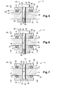
- connection device 2 comprises a contact piece 20, a seal 8, and fastening means 18, 36, 38, 52, 54, 56, 58, 60, 62, 64 of the connection device 2 on the support 10.
- the contact piece 20 is a piece driver intended to come into contact with the zone of contact 14 of the conductive support face 12. It is preferably made of conductive metal, as for example in a steel whose surface is treated against corrosion. It has a first face 22 and a second face 24 substantially opposite one to the other. The first face 22 has a face peripheral 30 and a central face 34, which are delimited by a shoulder 26 and which correspond respectively to a peripheral part 28 and to a central portion 32 of the contact piece 20. The second face 24 of the contact piece 20 is preferably substantially planar.
- the seal 8 is intended for keep airtight the contact zone 14 of the conductive face 12 to prevent it corrodes.
- the seal 8 is a seal ring.
- it is made of an elastomer compatible with environmental conditions (temperature, pressure, etc.) generally encountered in an aircraft.
- connection device 2 on the support 10 are able to maintain contact between the conductive support face 12 and the contact piece 20.
- the means of fixation may comprise a first thread 54 of the rod 52 and a thread 18 of the support hole 16, which cooperate to fix the rod 52 to the support 10.
- the means of fixation may include a second thread 56 of the rod 52 and a thread 38 of the coin hole of contact 36, which cooperate to secure the rod 52 to the contact piece 20, the latter being fixed to the support 10 by other fastening means.
- the three variants can also be combined, two by two or all three together.
- the first thread 54, the second thread 56 and the third thread 58 of the rod 52 may be identical or different from each other other.
- connection device 2 has two contact pieces 20, two seals 8, and fastening means 36, 60, 62, 64, 66, 70, 72, 76, 78, 80, 82 of the device of connection 2 on the support 10. It is particularly adapted to a support 10 having two faces 12 electrically conductive and substantially opposed to each other, and being traversed by a support hole 16 which opens on each of the two conducting faces 12.
- the two contact pieces 20 are of preferably similar to each other and similar to the contact piece 20 of the first embodiment of the connection device 2.
- the seals 8 are of preferably similar to each other and similar to the joint 8 of the first embodiment.
- the means of through fasteners 60, 62, 70, 72 comprise a screw / nut assembly 60, 62.
- the rod 52 of the screw 60 is intended, in use, to traverse the hole 36 of one contact pieces 20, then the hole 16 of the support 10, then the hole 36 of the other contact piece 20.
- the head 64 of the screw 60 is intended, in use, to lean against the second face 24 of one of the pieces 20 whereas the nut 62 is intended, in service, to lean against the second face 24 of the other of the contact pieces 20.
- the means of through fasteners have two clamps 70, 72.
- Each clamping piece 70, 72 comprises a cylindrical portion 74 terminating at one end by an end flange 76 extending towards outside, and provided at the other end with means of locking 78, 80.
- the locking means 78, 80 two clamping pieces 70, 72 are able to cooperate to lock together said two pieces of 70, 72.
- the end collars 76 are intended, in use, to lean against seconds respective faces 24 of the contact pieces 20.
- the locking means 78, 80 have projecting portions 78 of one of the clamping pieces 70 and recessed portions 80 of the other clamping piece 72.
- the protruding parts 78 and the recessed portions 80 are formed, respectively towards the end of the game cylindrical 74 which is opposed to the collar 76. They are intended, in use, to be to be mutually engaged under the action of a axial compression exerted on the two pieces of 70, 72 so as to fit one with the other.
- the end collar 76 of one of the clamping pieces 70, 72 is intended for lean against the second face 24 of one of the pieces 20, and the end flange 76 of the other of the clamping pieces 70, 72 is intended for lean against the second side 24 of the other piece of contact 20.
- the parts cylindrical 74 clamping pieces 70, 72 are axially hollow and the fastening means through-holes 60, 62, 70, 72 comprise, in addition, a screw / nut assembly 60, 62.
- the rod 52 of the screw 60 crosses one then the other of the pieces of tightening 70, 72, and the head 64 of screws 60 is against the end collar 76 of one of the two parts 70, 72 while the nut 62 builds against the end collar 76 of the other clamping parts 70, 72.
- each piece clamping device 70, 72 has an annular groove 84 arranged circumferentially on its outer face and near its end flange 76 (see Figure 8).
- the connection device 2 comprises in in addition to two annular sealing members 88, each annular sealing member 88 being intended, in service, to be inserted in one of said grooves 84.
- the annular members 88 are O-rings.
- the second face 24 of the part clamping device 20 preferably has a recess 90 arranged substantially centrally and intended for at least partially housing the end collar 76 of the clamping piece 70, 72 which rests on said second face 24 (see Figure 8).
- the clamping pieces 70, 72 are made of a conductive material to ensure the electrical contact of the metallization point, by example of metal as a steel whose surface can be treated against corrosion.
- the electrical contact is made by the screw / nut assembly 60, 62.
- the clamping pieces 70, 72 can in this case be made of a material non-conductive, for example plastic, this which reduces manufacturing costs, when the pieces are made in large quantities.
- the fastening means comprise a screw / nut assembly 60, 62, which can be accompanied by a clamping washer 66 placed side of the head of the screw 60, and / or a washer of tightening 66 placed on the side of the nut 62.
- a clamping washer 66 is illustrated in FIG. 8.
- connection device 2 includes retaining means 42, 44, 48 of each seal 8.
- the retaining means 42, 44, 48 of each seal 8 have a groove ring 42 formed on the peripheral face 30 of the contact piece 20 so as to be in service, next to the support face 12 corresponding.
- the gasket 8 is compressed between said peripheral face 30 and the support face 12 (arrows 99 in FIGS. 2 to 7), and retained by said throat 42.
- each seal 8 comprise an insert 44, intended, in use, to be interposed between the face peripheral 30 of the contact piece 20 and the face of support 12.
- the insert 44 is traversed by an insert hole 46 which is sized to receive and surround the central part 32 of the contact piece 20, while the peripheral face 30 of the piece of contact 20 is supported on said insert 44.
- the insert 44 is made of a non-conductive material, for example plastic material.
- the invention also relates to a support 10 having at least one electrically conductive face 12 provided with at least one connection device 2 according to the first aspect of the invention so as to achieve a point of metallization on the support 10.
- connection device 2 The fastening means 18, 36, 38, 52, 54, 56, 58, 60, 62, 64, 66, 70, 72, 76, 78, 80, 82 of the connection device 2 to the support 10 are adapted audit support 10.
- the support 10 comprises only one conductive face 12 and has a support hole 16 not traversing, it is preferably associated with said support 10 a connection device 2 according to the first or the second variant of the first embodiment.
- the support 10 comprises only one conductive face 12 and has a support hole 16 through, it is preferably associated with said support 10 a connection device 2 according to the third variant of the first embodiment.
- the support 10 has two faces conductive 12 substantially opposed to each other and has a support hole 16 through, one preferably associates with said support 10 a device for connection 2 according to the second embodiment.
- the conductive face 12 of the support 10 has at least one contact zone 14 for be in contact with the central face 34 of the room of corresponding contact, in order to achieve a point of metallization.
- This contact zone 14, illustrated on FIGS. 9 and 10 are stripped in such a way as to ensure the electrical contact.
- said contact zone 14 is preferably around an orifice of said support hole (s) 16.
- the metal parts are treated against corrosion, for example by means of nickel base.
Landscapes
- Engineering & Computer Science (AREA)
- Aviation & Aerospace Engineering (AREA)
- Connection Of Plates (AREA)
- Coupling Device And Connection With Printed Circuit (AREA)
- Connector Housings Or Holding Contact Members (AREA)
- Multi-Conductor Connections (AREA)
- Gasket Seals (AREA)
- Connections Effected By Soldering, Adhesion, Or Permanent Deformation (AREA)
- Connections By Means Of Piercing Elements, Nuts, Or Screws (AREA)
Applications Claiming Priority (2)
| Application Number | Priority Date | Filing Date | Title |
|---|---|---|---|
| FR0450045A FR2865073B1 (fr) | 2004-01-08 | 2004-01-08 | Dispositif de connexion electrique destine a realiser un point de metallisation, support muni d'un tel dispositif de connexion, et aeronef equipe d'un tel support |
| FR0450045 | 2004-01-08 |
Publications (2)
| Publication Number | Publication Date |
|---|---|
| EP1553661A1 true EP1553661A1 (de) | 2005-07-13 |
| EP1553661B1 EP1553661B1 (de) | 2008-04-09 |
Family
ID=34586502
Family Applications (1)
| Application Number | Title | Priority Date | Filing Date |
|---|---|---|---|
| EP05100056A Not-in-force EP1553661B1 (de) | 2004-01-08 | 2005-01-06 | Elektrische Anschlussvorrichtung zur Schaffung eines Metallisierungspunkts, Träger mit einer solchen Anschlussvorrichtung und mit einem solchen Träger augerüstetes Flugzeug |
Country Status (6)
| Country | Link |
|---|---|
| US (1) | US6991478B2 (de) |
| EP (1) | EP1553661B1 (de) |
| AT (1) | ATE392033T1 (de) |
| CA (1) | CA2491519C (de) |
| DE (1) | DE602005005860T2 (de) |
| FR (1) | FR2865073B1 (de) |
Cited By (3)
| Publication number | Priority date | Publication date | Assignee | Title |
|---|---|---|---|---|
| EP2451012A3 (de) * | 2010-11-05 | 2013-06-12 | HILTI Aktiengesellschaft | Erdungskontakt |
| KR20190140446A (ko) * | 2017-04-18 | 2019-12-19 | 힐티 악티엔게젤샤프트 | 접지 접촉부 |
| FR3084212A1 (fr) * | 2018-07-23 | 2020-01-24 | Nexter Electronics | Dispositif de connexion electrique pour un substrat metallique isole |
Families Citing this family (29)
| Publication number | Priority date | Publication date | Assignee | Title |
|---|---|---|---|---|
| US7284994B2 (en) * | 2005-06-21 | 2007-10-23 | Adc Telecommunications, Inc. | Grounding lug for armored cable and method |
| DE102005036105B3 (de) * | 2005-08-01 | 2006-11-16 | Semikron Elektronik Gmbh & Co. Kg | Elektrisches Bauteil |
| DE102007005178B4 (de) * | 2006-02-03 | 2016-10-27 | Sew-Eurodrive Gmbh & Co Kg | Elektrisches Gerät |
| US20090266935A1 (en) * | 2008-04-28 | 2009-10-29 | Paul Joern | Shell arrangement as well as aircraft or spacecraft |
| DE102008001416B4 (de) * | 2008-04-28 | 2013-09-26 | Airbus Operations Gmbh | Luft- oder Raumfahrzeug |
| DE102009026686A1 (de) * | 2009-06-03 | 2010-12-23 | Airbus France | Anordnung zum Blitzschutz einer elektronischen Einheit |
| JP5463742B2 (ja) * | 2009-06-10 | 2014-04-09 | 三菱電機株式会社 | 接続装置ならびにこれを用いた配電盤 |
| JP5654124B2 (ja) | 2010-06-16 | 2015-01-14 | ミューラー インターナショナル エルエルシーMueller International,Llc | インフラ監視装置、システム、および方法 |
| US9772250B2 (en) | 2011-08-12 | 2017-09-26 | Mueller International, Llc | Leak detector and sensor |
| DE102012017357A1 (de) * | 2012-08-31 | 2014-03-06 | Liebherr-Elektronik Gmbh | Hermetische Gehäuseanordnung |
| US8997336B2 (en) * | 2012-09-10 | 2015-04-07 | Renewable Energy Holdings, Llc | Air-tight and water-tight electrical bonding device |
| CN103618157A (zh) * | 2013-11-30 | 2014-03-05 | 国家电网公司 | 电力设备接地线连接装置 |
| DE102013021409A1 (de) | 2013-12-18 | 2015-06-18 | Daimler Ag | Wasserdichter Schraubkontakt zur Kontaktierung einer elektrischen oder elektronischen Vorrichtung |
| DE102014000231A1 (de) * | 2014-01-09 | 2015-07-09 | Sfs Intec Holding Ag | Clipmutter, Befestigungsanordnung und Verfahren zum Herstellen einer Clipmutter |
| US9680239B2 (en) | 2014-04-23 | 2017-06-13 | Ramco Specialties, Inc. | Grounding stud and electrical connections |
| DE102015004837A1 (de) | 2015-04-15 | 2016-10-20 | Daimler Ag | Haltevorrichtung zum Halten eines Objekts an einem Kraftwagen |
| EP3188322B1 (de) * | 2015-12-29 | 2018-01-31 | Axis AB | Erdungsklemme für eine elektronische vorrichtung |
| US10305178B2 (en) | 2016-02-12 | 2019-05-28 | Mueller International, Llc | Nozzle cap multi-band antenna assembly |
| US10283857B2 (en) | 2016-02-12 | 2019-05-07 | Mueller International, Llc | Nozzle cap multi-band antenna assembly |
| US9692193B1 (en) | 2016-07-28 | 2017-06-27 | Ge Aviation Systems, Llc | Connector having a plate seal and a conductor seal |
| US11196186B2 (en) * | 2016-11-28 | 2021-12-07 | Ppc Broadband, Inc. | Coaxial cable bonding/grounding blocks |
| DE102017119484A1 (de) * | 2017-08-25 | 2019-02-28 | Wobben Properties Gmbh | Windenergieanlagen-Rotorblatt und Blitzschutzsystem für ein Windenergieanlagen-Rotorblatt |
| US10167891B1 (en) * | 2018-03-08 | 2019-01-01 | International Business Machines Corporation | Self-reporting, grounded nut-clip |
| US10859462B2 (en) | 2018-09-04 | 2020-12-08 | Mueller International, Llc | Hydrant cap leak detector with oriented sensor |
| US11342656B2 (en) * | 2018-12-28 | 2022-05-24 | Mueller International, Llc | Nozzle cap encapsulated antenna system |
| US11473993B2 (en) | 2019-05-31 | 2022-10-18 | Mueller International, Llc | Hydrant nozzle cap |
| US11695225B2 (en) * | 2019-08-19 | 2023-07-04 | Carlisle Interconnect Technologies, Inc. | Electrical connector and bonding system |
| US11177587B1 (en) * | 2020-03-19 | 2021-11-16 | Facebook, Inc. | Ground lug holder |
| US11542690B2 (en) | 2020-05-14 | 2023-01-03 | Mueller International, Llc | Hydrant nozzle cap adapter |
Citations (3)
| Publication number | Priority date | Publication date | Assignee | Title |
|---|---|---|---|---|
| FR2265194A1 (de) * | 1974-03-21 | 1975-10-17 | Boeing Co | |
| EP0891007A1 (de) * | 1997-07-11 | 1999-01-13 | Hans-Günther Gänslein | Vorrichtung zum Anschluss einer elektrischen Leitung an einem Eisenbahnschienensteg o. dgl. |
| EP0971440A1 (de) * | 1998-07-10 | 2000-01-12 | Air LB International | Elektrischer Modul für Erdverbindung mit Stiftkontakten |
Family Cites Families (8)
| Publication number | Priority date | Publication date | Assignee | Title |
|---|---|---|---|---|
| US2061629A (en) * | 1933-07-20 | 1936-11-24 | Huxon Holding Corp | Rivet |
| US5213460A (en) * | 1991-05-24 | 1993-05-25 | Huck International, Inc. | High strength blind bolt with uniform high clamp over an extended grip range |
| US5429464A (en) * | 1994-02-16 | 1995-07-04 | Textron Inc. | Blind fastener with two-piece expander |
| US5603592A (en) * | 1994-10-03 | 1997-02-18 | Huck International, Inc. | High strength blind bolt with uniform high clamp over an extended grip range |
| EP1415370B1 (de) * | 2000-10-06 | 2011-11-16 | Amphenol Corporation | Anschlussblock mit schulterkontakt und durch kunststoffeinlage gehaltene ausgebildete masseplatte |
| EP1350286B1 (de) * | 2001-01-10 | 2010-06-02 | Newfrey LLC | Elektrischer kontaktbolzen mit kappe und verfahren zur befestigung eines elektrischen kontaktes |
| US6746285B2 (en) * | 2001-02-20 | 2004-06-08 | Newfrey Llc | Grounding stud |
| US6877996B1 (en) * | 2002-11-27 | 2005-04-12 | Senior Industries, Inc. | Grounding connector |
-
2004
- 2004-01-08 FR FR0450045A patent/FR2865073B1/fr not_active Expired - Fee Related
-
2005
- 2005-01-04 US US11/028,231 patent/US6991478B2/en not_active Expired - Fee Related
- 2005-01-05 CA CA2491519A patent/CA2491519C/en not_active Expired - Fee Related
- 2005-01-06 DE DE602005005860T patent/DE602005005860T2/de active Active
- 2005-01-06 EP EP05100056A patent/EP1553661B1/de not_active Not-in-force
- 2005-01-06 AT AT05100056T patent/ATE392033T1/de not_active IP Right Cessation
Patent Citations (3)
| Publication number | Priority date | Publication date | Assignee | Title |
|---|---|---|---|---|
| FR2265194A1 (de) * | 1974-03-21 | 1975-10-17 | Boeing Co | |
| EP0891007A1 (de) * | 1997-07-11 | 1999-01-13 | Hans-Günther Gänslein | Vorrichtung zum Anschluss einer elektrischen Leitung an einem Eisenbahnschienensteg o. dgl. |
| EP0971440A1 (de) * | 1998-07-10 | 2000-01-12 | Air LB International | Elektrischer Modul für Erdverbindung mit Stiftkontakten |
Cited By (4)
| Publication number | Priority date | Publication date | Assignee | Title |
|---|---|---|---|---|
| EP2451012A3 (de) * | 2010-11-05 | 2013-06-12 | HILTI Aktiengesellschaft | Erdungskontakt |
| KR20190140446A (ko) * | 2017-04-18 | 2019-12-19 | 힐티 악티엔게젤샤프트 | 접지 접촉부 |
| FR3084212A1 (fr) * | 2018-07-23 | 2020-01-24 | Nexter Electronics | Dispositif de connexion electrique pour un substrat metallique isole |
| EP3599666A1 (de) * | 2018-07-23 | 2020-01-29 | NEXTER Systems | Elektrische verbindungsvorrichtung für ein isoliertes metallsubstrat |
Also Published As
| Publication number | Publication date |
|---|---|
| CA2491519C (en) | 2011-11-15 |
| US6991478B2 (en) | 2006-01-31 |
| CA2491519A1 (en) | 2005-07-08 |
| ATE392033T1 (de) | 2008-04-15 |
| FR2865073B1 (fr) | 2009-11-13 |
| EP1553661B1 (de) | 2008-04-09 |
| DE602005005860D1 (de) | 2008-05-21 |
| FR2865073A1 (fr) | 2005-07-15 |
| DE602005005860T2 (de) | 2009-05-20 |
| US20050153586A1 (en) | 2005-07-14 |
Similar Documents
| Publication | Publication Date | Title |
|---|---|---|
| EP1553661B1 (de) | Elektrische Anschlussvorrichtung zur Schaffung eines Metallisierungspunkts, Träger mit einer solchen Anschlussvorrichtung und mit einem solchen Träger augerüstetes Flugzeug | |
| EP2086081B1 (de) | Isolierscheibe gegen Elektrizität zur Unterstützung eines linearen Leiters und diese Scheibe umfassende elektrische Einheit | |
| FR3078449A1 (fr) | Dispositif d'entree de cable pour cable electrique sous conduit | |
| US4305638A (en) | Coaxial connector with gasketed sealing cylinder | |
| EP3457499B1 (de) | Elektrische verbindungsvorrichtung | |
| FR2939245A1 (fr) | Dispositif de connexion d'un servomoteur a au moins un cable electrique. | |
| WO2008145878A1 (fr) | Accessoire du type backshell pour connecteur | |
| FR3035458A1 (fr) | Capuchon de fixation rotule | |
| FR3096840A1 (fr) | Dispositif et procédé de liaison mécanique et électrique de deux organes électriques de puissance | |
| FR2767959A1 (fr) | Dispositif passe-tige et ensemble passe-tige le comportant | |
| FR2932613A1 (fr) | Dispositif de connexion entre un cable electrique et une struture conductrice | |
| FR2752899A1 (fr) | Presse-etoupe muni d'une bague d'ancrage en matiere plastique metallisee | |
| EP0479684B1 (de) | Abgeschirmter, wasserdichter und elektrisch isolierter elektrischer Verbinder | |
| FR2990805A1 (fr) | Dispositif et procede de fixation | |
| FR2478882A1 (fr) | Fiche coaxiale femelle | |
| FR2608850A1 (fr) | Boitier de raccordement pour cables electriques | |
| FR2655122A1 (fr) | Joint d'etancheite pour connecteur electrique, et connecteur qui en est equipe. | |
| EP4037107A1 (de) | Elektrische verbindungsvorrichtung mit buchse | |
| FR3038459A1 (fr) | Connecteur electrique a blindage electromagnetique | |
| WO2023105136A1 (fr) | Dispositif de jonction électrique entre deux tronçons de câble électrique, procédé de raccordement de deux tronçons de câble électrique au moyen d'un tel dispositif et câble de puissance équipé d'un tel dispositif | |
| FR2699752A1 (fr) | Dispositif pour traversée étanche de câble, notamment dans une boîte de dérivation électrique de remorque ou de tracteur routier. | |
| WO2021223935A1 (fr) | Dispositif d'assemblage et d'evacuation des courants de fuite de deux portions d'enveloppes destinees a contenir un gaz sous pression | |
| EP2272135B1 (de) | Einrichtung zur verhinderung der erzeugung eines elektrischen bogens zwischen zwei leitfähigen elementen | |
| FR2806216A1 (fr) | Dispositif de connexion rapide d'un cable a une borne d'une source d'alimentation en energie electrique | |
| FR2747244A1 (fr) | Entree de cable ou de canalisation a montage rapide |
Legal Events
| Date | Code | Title | Description |
|---|---|---|---|
| PUAI | Public reference made under article 153(3) epc to a published international application that has entered the european phase |
Free format text: ORIGINAL CODE: 0009012 |
|
| AK | Designated contracting states |
Kind code of ref document: A1 Designated state(s): AT BE BG CH CY CZ DE DK EE ES FI FR GB GR HU IE IS IT LI LT LU MC NL PL PT RO SE SI SK TR |
|
| AX | Request for extension of the european patent |
Extension state: AL BA HR LV MK YU |
|
| 17P | Request for examination filed |
Effective date: 20060107 |
|
| AKX | Designation fees paid |
Designated state(s): AT BE BG CH CY CZ DE DK EE ES FI FR GB GR HU IE IS IT LI LT LU MC NL PL PT RO SE SI SK TR |
|
| 17Q | First examination report despatched |
Effective date: 20060714 |
|
| GRAP | Despatch of communication of intention to grant a patent |
Free format text: ORIGINAL CODE: EPIDOSNIGR1 |
|
| GRAS | Grant fee paid |
Free format text: ORIGINAL CODE: EPIDOSNIGR3 |
|
| GRAA | (expected) grant |
Free format text: ORIGINAL CODE: 0009210 |
|
| AK | Designated contracting states |
Kind code of ref document: B1 Designated state(s): AT BE BG CH CY CZ DE DK EE ES FI FR GB GR HU IE IS IT LI LT LU MC NL PL PT RO SE SI SK TR |
|
| REG | Reference to a national code |
Ref country code: GB Ref legal event code: FG4D Free format text: NOT ENGLISH |
|
| REG | Reference to a national code |
Ref country code: CH Ref legal event code: EP |
|
| REG | Reference to a national code |
Ref country code: IE Ref legal event code: FG4D Free format text: LANGUAGE OF EP DOCUMENT: FRENCH |
|
| REF | Corresponds to: |
Ref document number: 602005005860 Country of ref document: DE Date of ref document: 20080521 Kind code of ref document: P |
|
| REG | Reference to a national code |
Ref country code: SE Ref legal event code: TRGR |
|
| PG25 | Lapsed in a contracting state [announced via postgrant information from national office to epo] |
Ref country code: SI Free format text: LAPSE BECAUSE OF FAILURE TO SUBMIT A TRANSLATION OF THE DESCRIPTION OR TO PAY THE FEE WITHIN THE PRESCRIBED TIME-LIMIT Effective date: 20080409 |
|
| NLV1 | Nl: lapsed or annulled due to failure to fulfill the requirements of art. 29p and 29m of the patents act | ||
| PG25 | Lapsed in a contracting state [announced via postgrant information from national office to epo] |
Ref country code: PT Free format text: LAPSE BECAUSE OF FAILURE TO SUBMIT A TRANSLATION OF THE DESCRIPTION OR TO PAY THE FEE WITHIN THE PRESCRIBED TIME-LIMIT Effective date: 20080909 Ref country code: ES Free format text: LAPSE BECAUSE OF FAILURE TO SUBMIT A TRANSLATION OF THE DESCRIPTION OR TO PAY THE FEE WITHIN THE PRESCRIBED TIME-LIMIT Effective date: 20080720 Ref country code: FI Free format text: LAPSE BECAUSE OF FAILURE TO SUBMIT A TRANSLATION OF THE DESCRIPTION OR TO PAY THE FEE WITHIN THE PRESCRIBED TIME-LIMIT Effective date: 20080409 Ref country code: NL Free format text: LAPSE BECAUSE OF FAILURE TO SUBMIT A TRANSLATION OF THE DESCRIPTION OR TO PAY THE FEE WITHIN THE PRESCRIBED TIME-LIMIT Effective date: 20080409 Ref country code: BG Free format text: LAPSE BECAUSE OF FAILURE TO SUBMIT A TRANSLATION OF THE DESCRIPTION OR TO PAY THE FEE WITHIN THE PRESCRIBED TIME-LIMIT Effective date: 20080709 |
|
| PG25 | Lapsed in a contracting state [announced via postgrant information from national office to epo] |
Ref country code: AT Free format text: LAPSE BECAUSE OF FAILURE TO SUBMIT A TRANSLATION OF THE DESCRIPTION OR TO PAY THE FEE WITHIN THE PRESCRIBED TIME-LIMIT Effective date: 20080409 Ref country code: PL Free format text: LAPSE BECAUSE OF FAILURE TO SUBMIT A TRANSLATION OF THE DESCRIPTION OR TO PAY THE FEE WITHIN THE PRESCRIBED TIME-LIMIT Effective date: 20080409 |
|
| REG | Reference to a national code |
Ref country code: IE Ref legal event code: FD4D |
|
| PG25 | Lapsed in a contracting state [announced via postgrant information from national office to epo] |
Ref country code: IS Free format text: LAPSE BECAUSE OF FAILURE TO SUBMIT A TRANSLATION OF THE DESCRIPTION OR TO PAY THE FEE WITHIN THE PRESCRIBED TIME-LIMIT Effective date: 20080809 |
|
| PG25 | Lapsed in a contracting state [announced via postgrant information from national office to epo] |
Ref country code: LT Free format text: LAPSE BECAUSE OF FAILURE TO SUBMIT A TRANSLATION OF THE DESCRIPTION OR TO PAY THE FEE WITHIN THE PRESCRIBED TIME-LIMIT Effective date: 20080409 Ref country code: CZ Free format text: LAPSE BECAUSE OF FAILURE TO SUBMIT A TRANSLATION OF THE DESCRIPTION OR TO PAY THE FEE WITHIN THE PRESCRIBED TIME-LIMIT Effective date: 20080409 Ref country code: DK Free format text: LAPSE BECAUSE OF FAILURE TO SUBMIT A TRANSLATION OF THE DESCRIPTION OR TO PAY THE FEE WITHIN THE PRESCRIBED TIME-LIMIT Effective date: 20080409 Ref country code: IE Free format text: LAPSE BECAUSE OF FAILURE TO SUBMIT A TRANSLATION OF THE DESCRIPTION OR TO PAY THE FEE WITHIN THE PRESCRIBED TIME-LIMIT Effective date: 20080409 |
|
| PLBE | No opposition filed within time limit |
Free format text: ORIGINAL CODE: 0009261 |
|
| STAA | Information on the status of an ep patent application or granted ep patent |
Free format text: STATUS: NO OPPOSITION FILED WITHIN TIME LIMIT |
|
| PG25 | Lapsed in a contracting state [announced via postgrant information from national office to epo] |
Ref country code: RO Free format text: LAPSE BECAUSE OF FAILURE TO SUBMIT A TRANSLATION OF THE DESCRIPTION OR TO PAY THE FEE WITHIN THE PRESCRIBED TIME-LIMIT Effective date: 20080409 Ref country code: SK Free format text: LAPSE BECAUSE OF FAILURE TO SUBMIT A TRANSLATION OF THE DESCRIPTION OR TO PAY THE FEE WITHIN THE PRESCRIBED TIME-LIMIT Effective date: 20080409 |
|
| 26N | No opposition filed |
Effective date: 20090112 |
|
| PG25 | Lapsed in a contracting state [announced via postgrant information from national office to epo] |
Ref country code: EE Free format text: LAPSE BECAUSE OF FAILURE TO SUBMIT A TRANSLATION OF THE DESCRIPTION OR TO PAY THE FEE WITHIN THE PRESCRIBED TIME-LIMIT Effective date: 20080409 |
|
| PG25 | Lapsed in a contracting state [announced via postgrant information from national office to epo] |
Ref country code: MC Free format text: LAPSE BECAUSE OF NON-PAYMENT OF DUE FEES Effective date: 20090131 |
|
| REG | Reference to a national code |
Ref country code: CH Ref legal event code: PL |
|
| PG25 | Lapsed in a contracting state [announced via postgrant information from national office to epo] |
Ref country code: CY Free format text: LAPSE BECAUSE OF FAILURE TO SUBMIT A TRANSLATION OF THE DESCRIPTION OR TO PAY THE FEE WITHIN THE PRESCRIBED TIME-LIMIT Effective date: 20080409 |
|
| PG25 | Lapsed in a contracting state [announced via postgrant information from national office to epo] |
Ref country code: LI Free format text: LAPSE BECAUSE OF NON-PAYMENT OF DUE FEES Effective date: 20090131 Ref country code: CH Free format text: LAPSE BECAUSE OF NON-PAYMENT OF DUE FEES Effective date: 20090131 |
|
| PG25 | Lapsed in a contracting state [announced via postgrant information from national office to epo] |
Ref country code: BE Free format text: LAPSE BECAUSE OF NON-PAYMENT OF DUE FEES Effective date: 20090131 |
|
| PG25 | Lapsed in a contracting state [announced via postgrant information from national office to epo] |
Ref country code: GR Free format text: LAPSE BECAUSE OF FAILURE TO SUBMIT A TRANSLATION OF THE DESCRIPTION OR TO PAY THE FEE WITHIN THE PRESCRIBED TIME-LIMIT Effective date: 20080710 |
|
| PG25 | Lapsed in a contracting state [announced via postgrant information from national office to epo] |
Ref country code: LU Free format text: LAPSE BECAUSE OF NON-PAYMENT OF DUE FEES Effective date: 20090106 |
|
| PG25 | Lapsed in a contracting state [announced via postgrant information from national office to epo] |
Ref country code: HU Free format text: LAPSE BECAUSE OF FAILURE TO SUBMIT A TRANSLATION OF THE DESCRIPTION OR TO PAY THE FEE WITHIN THE PRESCRIBED TIME-LIMIT Effective date: 20081010 |
|
| REG | Reference to a national code |
Ref country code: GB Ref legal event code: 732E Free format text: REGISTERED BETWEEN 20110721 AND 20110727 |
|
| PG25 | Lapsed in a contracting state [announced via postgrant information from national office to epo] |
Ref country code: TR Free format text: LAPSE BECAUSE OF FAILURE TO SUBMIT A TRANSLATION OF THE DESCRIPTION OR TO PAY THE FEE WITHIN THE PRESCRIBED TIME-LIMIT Effective date: 20080409 |
|
| REG | Reference to a national code |
Ref country code: FR Ref legal event code: CA Effective date: 20110916 Ref country code: FR Ref legal event code: CJ Effective date: 20110916 Ref country code: FR Ref legal event code: TP Owner name: AIRBUS HOLDING, FR Effective date: 20110913 Ref country code: FR Ref legal event code: CD Owner name: AIRBUS HOLDING, FR Effective date: 20110916 |
|
| REG | Reference to a national code |
Ref country code: DE Ref legal event code: R082 Ref document number: 602005005860 Country of ref document: DE Representative=s name: HENKEL, BREUER & PARTNER, DE |
|
| REG | Reference to a national code |
Ref country code: DE Ref legal event code: R081 Ref document number: 602005005860 Country of ref document: DE Owner name: AIRBUS OPERATIONS SAS, FR Free format text: FORMER OWNER: AIRBUS FRANCE, TOULOUSE, FR Effective date: 20120326 Ref country code: DE Ref legal event code: R082 Ref document number: 602005005860 Country of ref document: DE Representative=s name: PATENTANWAELTE HENKEL, BREUER & PARTNER, DE Effective date: 20120326 Ref country code: DE Ref legal event code: R082 Ref document number: 602005005860 Country of ref document: DE Representative=s name: PATENTANWAELTE HENKEL, BREUER & PARTNER MBB, DE Effective date: 20120326 |
|
| PGFP | Annual fee paid to national office [announced via postgrant information from national office to epo] |
Ref country code: IT Payment date: 20120123 Year of fee payment: 8 |
|
| PGFP | Annual fee paid to national office [announced via postgrant information from national office to epo] |
Ref country code: SE Payment date: 20130122 Year of fee payment: 9 |
|
| REG | Reference to a national code |
Ref country code: SE Ref legal event code: EUG |
|
| PG25 | Lapsed in a contracting state [announced via postgrant information from national office to epo] |
Ref country code: SE Free format text: LAPSE BECAUSE OF NON-PAYMENT OF DUE FEES Effective date: 20140107 |
|
| REG | Reference to a national code |
Ref country code: FR Ref legal event code: PLFP Year of fee payment: 12 |
|
| PG25 | Lapsed in a contracting state [announced via postgrant information from national office to epo] |
Ref country code: IT Free format text: LAPSE BECAUSE OF NON-PAYMENT OF DUE FEES Effective date: 20140106 |
|
| REG | Reference to a national code |
Ref country code: FR Ref legal event code: PLFP Year of fee payment: 13 |
|
| PGFP | Annual fee paid to national office [announced via postgrant information from national office to epo] |
Ref country code: DE Payment date: 20170120 Year of fee payment: 13 Ref country code: FR Payment date: 20170120 Year of fee payment: 13 |
|
| PGFP | Annual fee paid to national office [announced via postgrant information from national office to epo] |
Ref country code: GB Payment date: 20170119 Year of fee payment: 13 |
|
| REG | Reference to a national code |
Ref country code: DE Ref legal event code: R119 Ref document number: 602005005860 Country of ref document: DE |
|
| GBPC | Gb: european patent ceased through non-payment of renewal fee |
Effective date: 20180106 |
|
| PG25 | Lapsed in a contracting state [announced via postgrant information from national office to epo] |
Ref country code: FR Free format text: LAPSE BECAUSE OF NON-PAYMENT OF DUE FEES Effective date: 20180131 Ref country code: DE Free format text: LAPSE BECAUSE OF NON-PAYMENT OF DUE FEES Effective date: 20180801 |
|
| REG | Reference to a national code |
Ref country code: FR Ref legal event code: ST Effective date: 20180928 |
|
| PG25 | Lapsed in a contracting state [announced via postgrant information from national office to epo] |
Ref country code: GB Free format text: LAPSE BECAUSE OF NON-PAYMENT OF DUE FEES Effective date: 20180106 |