EP1553268B1 - Dispositif de filtration, en particulier du système d'échappement d'un moteur à combustion interne - Google Patents
Dispositif de filtration, en particulier du système d'échappement d'un moteur à combustion interne Download PDFInfo
- Publication number
- EP1553268B1 EP1553268B1 EP04105579A EP04105579A EP1553268B1 EP 1553268 B1 EP1553268 B1 EP 1553268B1 EP 04105579 A EP04105579 A EP 04105579A EP 04105579 A EP04105579 A EP 04105579A EP 1553268 B1 EP1553268 B1 EP 1553268B1
- Authority
- EP
- European Patent Office
- Prior art keywords
- filter
- wall
- pressure sensor
- filter device
- pressure sensors
- Prior art date
- Legal status (The legal status is an assumption and is not a legal conclusion. Google has not performed a legal analysis and makes no representation as to the accuracy of the status listed.)
- Expired - Lifetime
Links
Images


Classifications
-
- F—MECHANICAL ENGINEERING; LIGHTING; HEATING; WEAPONS; BLASTING
- F01—MACHINES OR ENGINES IN GENERAL; ENGINE PLANTS IN GENERAL; STEAM ENGINES
- F01N—GAS-FLOW SILENCERS OR EXHAUST APPARATUS FOR MACHINES OR ENGINES IN GENERAL; GAS-FLOW SILENCERS OR EXHAUST APPARATUS FOR INTERNAL-COMBUSTION ENGINES
- F01N3/00—Exhaust or silencing apparatus having means for purifying, rendering innocuous, or otherwise treating exhaust
- F01N3/02—Exhaust or silencing apparatus having means for purifying, rendering innocuous, or otherwise treating exhaust for cooling, or for removing solid constituents of, exhaust
- F01N3/021—Exhaust or silencing apparatus having means for purifying, rendering innocuous, or otherwise treating exhaust for cooling, or for removing solid constituents of, exhaust by means of filters
- F01N3/023—Exhaust or silencing apparatus having means for purifying, rendering innocuous, or otherwise treating exhaust for cooling, or for removing solid constituents of, exhaust by means of filters using means for regenerating the filters, e.g. by burning trapped particles
-
- F—MECHANICAL ENGINEERING; LIGHTING; HEATING; WEAPONS; BLASTING
- F01—MACHINES OR ENGINES IN GENERAL; ENGINE PLANTS IN GENERAL; STEAM ENGINES
- F01N—GAS-FLOW SILENCERS OR EXHAUST APPARATUS FOR MACHINES OR ENGINES IN GENERAL; GAS-FLOW SILENCERS OR EXHAUST APPARATUS FOR INTERNAL-COMBUSTION ENGINES
- F01N11/00—Monitoring or diagnostic devices for exhaust-gas treatment apparatus
- F01N11/002—Monitoring or diagnostic devices for exhaust-gas treatment apparatus the diagnostic devices measuring or estimating temperature or pressure in, or downstream of the exhaust apparatus
-
- F—MECHANICAL ENGINEERING; LIGHTING; HEATING; WEAPONS; BLASTING
- F01—MACHINES OR ENGINES IN GENERAL; ENGINE PLANTS IN GENERAL; STEAM ENGINES
- F01N—GAS-FLOW SILENCERS OR EXHAUST APPARATUS FOR MACHINES OR ENGINES IN GENERAL; GAS-FLOW SILENCERS OR EXHAUST APPARATUS FOR INTERNAL-COMBUSTION ENGINES
- F01N9/00—Electrical control of exhaust gas treating apparatus
- F01N9/002—Electrical control of exhaust gas treating apparatus of filter regeneration
-
- F—MECHANICAL ENGINEERING; LIGHTING; HEATING; WEAPONS; BLASTING
- F01—MACHINES OR ENGINES IN GENERAL; ENGINE PLANTS IN GENERAL; STEAM ENGINES
- F01N—GAS-FLOW SILENCERS OR EXHAUST APPARATUS FOR MACHINES OR ENGINES IN GENERAL; GAS-FLOW SILENCERS OR EXHAUST APPARATUS FOR INTERNAL-COMBUSTION ENGINES
- F01N2560/00—Exhaust systems with means for detecting or measuring exhaust gas components or characteristics
- F01N2560/08—Exhaust systems with means for detecting or measuring exhaust gas components or characteristics the means being a pressure sensor
-
- F—MECHANICAL ENGINEERING; LIGHTING; HEATING; WEAPONS; BLASTING
- F01—MACHINES OR ENGINES IN GENERAL; ENGINE PLANTS IN GENERAL; STEAM ENGINES
- F01N—GAS-FLOW SILENCERS OR EXHAUST APPARATUS FOR MACHINES OR ENGINES IN GENERAL; GAS-FLOW SILENCERS OR EXHAUST APPARATUS FOR INTERNAL-COMBUSTION ENGINES
- F01N2560/00—Exhaust systems with means for detecting or measuring exhaust gas components or characteristics
- F01N2560/14—Exhaust systems with means for detecting or measuring exhaust gas components or characteristics having more than one sensor of one kind
-
- Y—GENERAL TAGGING OF NEW TECHNOLOGICAL DEVELOPMENTS; GENERAL TAGGING OF CROSS-SECTIONAL TECHNOLOGIES SPANNING OVER SEVERAL SECTIONS OF THE IPC; TECHNICAL SUBJECTS COVERED BY FORMER USPC CROSS-REFERENCE ART COLLECTIONS [XRACs] AND DIGESTS
- Y02—TECHNOLOGIES OR APPLICATIONS FOR MITIGATION OR ADAPTATION AGAINST CLIMATE CHANGE
- Y02T—CLIMATE CHANGE MITIGATION TECHNOLOGIES RELATED TO TRANSPORTATION
- Y02T10/00—Road transport of goods or passengers
- Y02T10/10—Internal combustion engine [ICE] based vehicles
- Y02T10/40—Engine management systems
Definitions
- the invention relates to a filter device, in particular for an exhaust system of an internal combustion engine, which filters out particles from a gas stream and which has a housing and at least one filter structure arranged in the housing, through which the gas flow can pass.
- a filter device of the type mentioned above is known from DE 100 14 224 A1.
- an exhaust system with a pre-catalyst and a filter which belongs to a diesel internal combustion engine.
- a pressure sensor is provided in each case.
- These two sensors act as a differential pressure sensor and provide a differential pressure signal that characterizes the differential pressure between the inlet and outlet of the pre-catalyst and filter arrangement.
- a loading condition of the filter is determined.
- the knowledge of the current load state of the filter is very important for the operation of the internal combustion engine and in particular the exhaust system. If the filter exceeds a certain load state, the exhaust back pressure increases, which can lead to an impairment of the operation of the internal combustion engine. It is therefore known, when the filter has reached a certain loading state, to regenerate it, for example by burning the soot particles retained in the filter. Regeneration must be timely, as it will be affected by excessive loading. But it should not be too often done to increase the fuel consumption of the internal combustion engine unnecessarily.
- DE 101 28 936 A1 discloses a filter device with a filter structure comprising a plurality of wedge-shaped filter bags, which are bounded by filter walls.
- the material used for the filter structure is an open-pore sintered metal.
- the present invention has the object to form a filter device of the type mentioned so that their loading condition can be determined as accurately as possible.
- the filter structure comprises at least one filter wall made of an open-pored filter material, and that at least two paired pressure sensors are provided, of which a pressure sensor is arranged at least approximately immediately upstream and the other pressure sensor is arranged at least approximately immediately downstream of the filter wall.
- the filter structure comprises filter pockets which are delimited by filter walls and a flow section located upstream of the filter walls which is separated by a sealing wall from a region downstream of the filter wall, and in which the two pressure sensors of a pressure sensor pair are on both sides the sealing wall are arranged.
- This location is very accessible, which facilitates the integration of the pressure sensor pair in the filter device.
- the filter structure has filter pockets, which are bounded by filter walls, and that the two pressure sensors of a pressure sensor pair are arranged on both sides of a filter wall at least approximately opposite each other. This results in particularly precise measurement results.
- the filter device comprises a plurality of pressure sensor pairs, and that the pressure sensors of a pressure sensor pair are spaced apart from the pressure sensors of another pair of pressure sensors in the flow direction. This allows the measurement of the pressure drop at different locations of the filter wall. As a result, conclusions can be drawn on the local loading of the filter device with particles. As a result, an even more precise detection of the loading state of the filter device is made possible.
- the filter device according to the invention works particularly well when the filter material has a open-pore structure, for example a sintered material comprises.
- a diesel internal combustion engine carries in Figure 1 in total the reference numeral 10. It comprises an engine block 12 and an exhaust system 14.
- the exhaust system 14 in turn comprises an exhaust pipe 16, in which a filter device 18 is arranged.
- This comprises a filter wall 20 indicated only schematically in FIG. 1 by a dashed line.
- a first pressure sensor 22 and immediately downstream of the filter wall 20 a second pressure sensor 24 are arranged.
- Both pressure sensors 22 and 24 provide signals to a control and regulating device 26. This is in turn connected to a fault memory 28.
- the control and regulating device 26 also generally controls the operation of the internal combustion engine 10, which is indicated by a dashed line connecting the control and regulating device 26 with the engine block 12.
- the filter device 18 is shown in more detail in Figure 2: It comprises a cylindrical housing 30 with an inlet 32 and an outlet 34. From the inlet 32, the diameter of the housing 30 widens conically towards a central portion 36. In the region of the outlet 34, the diameter decreases analogously from the central portion 36 to the outlet 34.
- an overall cylindrical filter structure 38 is received in the central portion 36 of the housing 30, in the central portion 36 of the housing 30, in the central portion 36 of the housing 30, an overall cylindrical filter structure 38 is received.
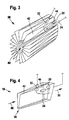
- This is shown in more detail in Figure 3 and comprises a central and cylindrical, coaxial with the longitudinal axis of the housing 30 cavity 40, from the imaginary peripheral wall, a plurality of filter walls 20 extend radially outward (in Figure 3, for clarity, only one filter wall provided with a reference numeral).
- the filter walls 20 are approximately rectangular. A front longitudinal edge of a filter wall 20 is connected to the front Longitudinal edge of the adjacent on one side of the filter wall 20, whereas the rear longitudinal edge of the filter wall 20 is connected to the corresponding rear longitudinal edge of the adjacent filter wall 20 on the other side. This results in a zigzag-like structure in the radial plan view, which forms cake-piece-like filter pockets 44 and intermediate free spaces 42 between the filter walls 20.
- Those free spaces 42 are open radially inward, radially outward, and at the upstream (ie left in FIG.) Edge, whereas at their downstream (ie, right in FIG. 2) edge they are closed by the adjoining rear edges of the filter walls 20.
- the filter pockets 44 are closed radially inward and radially outward and at their upstream (ie in FIG. 2, left) edge, whereas they are open at their downstream (that is, in FIG. 2, right) edge.
- the filter walls 20, which define the free spaces 42 and the filter pockets 44 are made of an open-pored material, for example sintered metal.
- the filter structure 38 is clamped fluid-tight in the housing 30 at its right in Figure 2 and radially outer edge in a radially inwardly extending flange 46 of the housing 30.
- the cavity 40 is closed analogously thereto at its right in Figure 2 end by a sealing wall 48.
- the two pressure sensors 22 and 24 are arranged on both sides of the sealing wall 48.
- the exhaust system 14 shown in FIG. 1 and the filter device 18 shown in FIG. 2 operate as follows: During operation of the internal combustion engine 10, soot particles are produced during the combustion of fuel. These are from the engine block 12 via the exhaust pipe 16 derived. They pass into the housing 30 of the filter device 18 via the inlet 32. There, the exhaust gas flow flows according to the arrows 50 into the free spaces 42, passes through the filter wall 20, enters the filter pockets 44 and leaves the filter device 18 via the outlet 34 Passing through the filter wall 20, soot particles present in the exhaust gas are deposited on the filter wall 20 and deposited there.
- the exhaust gas flow experiences a pressure drop in the filter device 18 not only because of the filter wall 20.
- turbulence also occurs which causes a pressure drop.
- this pressure drop is independent of the filter function of the filter device 18.
- This pressure drop is also independent of the function of the filter wall 20 or of its charge of soot particles.
- the filter device 18 when the filter device 18 is still comparatively "clean", that is to say still little soot particles are deposited in the filter device 18, a function diagnosis of the filter wall 20 can be carried out.
- a particularly small pressure drop across the filter wall 20 in the case of a "clean" filter device 18 would indicate, for example, damage, for example a hole, of the filter wall 20. This would lead to a corresponding entry in the error memory 28, which can be read by a diagnostic device. Since, due to the positioning of the two sensors 22 and 24, the loading of the filter wall 20 with soot particles can be detected comparatively precisely, regeneration measures of the filter device 18, for example a burning off of the deposited soot particles, can be initiated precisely at the required time. As a result, the reliability of the internal combustion engine 10 is increased and ultimately even the emission behavior is improved and the fuel consumption is lowered.
- FIG. 3 The illustration in FIG. 3 was already in connection with the explanation of the filter structure 38 of the filter device 18 of Figure 2 has been introduced.
- an arrangement of the two pressure sensors 22 and 24 is shown in Figure 3, which differs from the arrangement in Figure 2:
- the two pressure sensors 22 and 24 are not on both sides of the sealing wall 48, but immediately on both sides of between arranged a free space 42 and a filter bag 44 filter wall 20.
- the actual sensor tips of the two pressure sensors 22 and 24 are approximately opposite.
- FIG. 4 in which the filter structure 38 is shown only in the region of the sensors 22 and 24.
- FIG. 5 a plurality of adjacent filter bags 44 are shown. Unlike in the previous embodiments, however, not only two pressure sensors 22 and 24, but a total of three pressure sensor pairs A, B, C are present here, with the corresponding pressure sensors 22a and 24a, 22b and 24b, and 22c and 24c.
- the pressure sensors 22 and 24 of a pair A, B, C are arranged opposite each other on both sides of the filter wall, wherein in the flow direction (arrows 50) seen first the pressure sensor pair A, then with a distance the pressure sensor pair B, and then again the pressure sensor pair C is provided ,
Landscapes
- Engineering & Computer Science (AREA)
- Chemical & Material Sciences (AREA)
- Combustion & Propulsion (AREA)
- Mechanical Engineering (AREA)
- General Engineering & Computer Science (AREA)
- Chemical Kinetics & Catalysis (AREA)
- Processes For Solid Components From Exhaust (AREA)
- Filtering Of Dispersed Particles In Gases (AREA)
Claims (5)
- Dispositif de filtration (18), en particulier pour un système d'échappement (14) d'un moteur à combustion interne (10), qui filtre des particules (56) extraites d'un courant de gaz (50) avec une enceinte (30) et dans l'enceinte (30), au moins une structure de filtre (38) traversée par le courant de gaz (50),
caractérisé en ce que
la structure de filtre (38) comprend au moins une paroi de filtre (20) et au moins deux capteurs de pression (22, 24) disposés par paires, le premier capteur de pression (22) étant placé au moins presque directement en amont et l'autre capteur de pression (24) au moins presque directement en aval de la paroi de filtre (20). - Dispositif de filtration (18) selon la revendication 1,
caractérisé en ce que
la structure de filtre (38) présente des poches filtrantes (44), délimitées par des parois de filtre (20), et un segment d'écoulement (40) en amont des poches filtrantes est séparé d'une zone en aval de la structure de filtre (38) par une paroi d'étanchéité (48), et les deux capteurs de pression (22, 24) d'une paire de capteurs de pression sont sur les deux côtés de la paroi d'étanchéité (48). - Dispositif de filtration (18) selon l'une quelconque des revendications 1 ou 2,
caractérisé en ce que
la structure de filtre (38) présente des poches filtrantes (42) délimitées par des parois de filtre (20), et les deux capteurs de pression (22, 24) d'une paire de capteurs de pression sont au moins approximativement en face l'un de l'autre sur les deux côtés d'une paroi de filtre intermédiaire (20). - Dispositif de filtration (18) selon la revendication 4,
caractérisé par
plusieurs paires de capteurs de pression (A, B, C) dont les capteurs de pression (22, 24) d'une paire de capteurs de pression (A, B, C) sont espacés des capteurs de pression (22, 24) d'une autre paire de capteurs de pression (A, B, C) dans la direction de l'écoulement (50). - Dispositif de filtration (18) selon l'une quelconque des revendications précédentes,
caractérisé en ce que
le matériau du filtre comprend un métal fritté.
Applications Claiming Priority (2)
| Application Number | Priority Date | Filing Date | Title |
|---|---|---|---|
| DE102004001421A DE102004001421A1 (de) | 2004-01-09 | 2004-01-09 | Filtereinrichtung, insbesondere für eine Abgasanlage einer Brennkraftmaschine |
| DE102004001421 | 2004-01-09 |
Publications (2)
| Publication Number | Publication Date |
|---|---|
| EP1553268A1 EP1553268A1 (fr) | 2005-07-13 |
| EP1553268B1 true EP1553268B1 (fr) | 2006-08-23 |
Family
ID=34585371
Family Applications (1)
| Application Number | Title | Priority Date | Filing Date |
|---|---|---|---|
| EP04105579A Expired - Lifetime EP1553268B1 (fr) | 2004-01-09 | 2004-11-08 | Dispositif de filtration, en particulier du système d'échappement d'un moteur à combustion interne |
Country Status (2)
| Country | Link |
|---|---|
| EP (1) | EP1553268B1 (fr) |
| DE (2) | DE102004001421A1 (fr) |
Families Citing this family (1)
| Publication number | Priority date | Publication date | Assignee | Title |
|---|---|---|---|---|
| DE102005049690A1 (de) * | 2005-10-14 | 2007-04-19 | Robert Bosch Gmbh | Temperaturvergleichmässigender Innenkanal für ein Filterelement und Filter zur Abgasnachbehandlung |
Family Cites Families (4)
| Publication number | Priority date | Publication date | Assignee | Title |
|---|---|---|---|---|
| JPH0711936A (ja) * | 1993-06-29 | 1995-01-13 | Toyota Autom Loom Works Ltd | 排気ガス浄化装置 |
| JP3598542B2 (ja) * | 1994-10-11 | 2004-12-08 | 株式会社デンソー | ディーゼル内燃機関の排気浄化装置 |
| DE10014224A1 (de) * | 1999-05-07 | 2000-11-30 | Bosch Gmbh Robert | Verfahren und Vorrichtung zur Steuerung einer Brennkraftmaschine mit einem Abgasnachbehandlungssytem |
| DE10128936A1 (de) * | 2001-06-18 | 2003-01-02 | Hjs Fahrzeugtechnik Gmbh & Co | Partikelfilter, insbesondere für Abgase von Dieselbrennkraftmaschinen |
-
2004
- 2004-01-09 DE DE102004001421A patent/DE102004001421A1/de not_active Withdrawn
- 2004-11-08 DE DE502004001259T patent/DE502004001259D1/de not_active Expired - Lifetime
- 2004-11-08 EP EP04105579A patent/EP1553268B1/fr not_active Expired - Lifetime
Also Published As
| Publication number | Publication date |
|---|---|
| DE502004001259D1 (de) | 2006-10-05 |
| DE102004001421A1 (de) | 2005-08-04 |
| EP1553268A1 (fr) | 2005-07-13 |
Similar Documents
| Publication | Publication Date | Title |
|---|---|---|
| EP2078143B1 (fr) | Installation d'épuration des gaz d'échappement d'un moteur à combustion interne | |
| EP1502016B1 (fr) | Dispositif et procede permettant de determiner un defaut de fonctionnement d'un filtre | |
| EP1488077B1 (fr) | Aube de turbine refroidie | |
| EP2206897B1 (fr) | Dispositif d'alimentation pour un système SCR | |
| EP2252780B1 (fr) | Procédé pour déterminer l'état de charge d'un filtre à particules monté dans le tuyau de gaz d'échappement d'un moteur à combustion interne ainsi que dispositif de réduction de l'émission de particules pour un moteur à combustion interne | |
| DE102009043577A1 (de) | Entkoppelelement | |
| EP3298254B1 (fr) | Système d'échappement avec capteur de gaz, en particulier avec un capteur de matières particulaires | |
| DE202008003055U1 (de) | Druckminderer-Filter Anordnung mit Leckageschutz | |
| EP2401483A1 (fr) | Dispositif de traitement des gaz d'échappement et procédé de mise en uvre d'un dispositif de traitement des gaz d'échappement | |
| DE102012001314A1 (de) | Kraftstofftankentlüftungssystem für ein Kraftfahrzeug | |
| EP1490586B1 (fr) | Filtre a particules et procede pour nettoyer des gaz d'echappement | |
| EP1553268B1 (fr) | Dispositif de filtration, en particulier du système d'échappement d'un moteur à combustion interne | |
| EP2982841B1 (fr) | Procédé de surveillance d'état d'un filtre à particules, système de gaz d'échappement et dispositif de mesure | |
| DE102018107733A1 (de) | Verfahren und System zum Erfassen von Abgasfeinstaub | |
| EP4095363A1 (fr) | Procédé de détermination d'un besoin de régénération pour un filtre particulaire des gaz d'échappement, ainsi qu'installation de gaz d'échappement | |
| DE102005018271A1 (de) | Verfahren und Vorrichtung zur Diagnose eines Schubumluftventils eines Laders r | |
| WO2009112384A2 (fr) | Dispositif de filtrage notamment destiné à un système de gaz d'échappement d'un moteur à combustion interne | |
| DE20314408U1 (de) | Abgaspartikelfilter | |
| EP2960452B1 (fr) | Système d'échappement pour moteurs à combustion interne | |
| DE102014200534A1 (de) | Zweistufige Partikelfilteranordnung | |
| DE202014100157U1 (de) | Zweistufige Partikelfilteranordnung | |
| DE102019212174B3 (de) | Verfahren und Vorrichtung zur Steuerung des Betriebs eines Partikelfilters eines Kraftfahrzeugs | |
| DE102017117140A1 (de) | Verfahren und System zum Erfassen von Feinstaub in Abgas | |
| DE102014019641A1 (de) | Abgasanlage für eine Brennkraftmaschine | |
| DE102014200535A1 (de) | Zweistufige Partikelfilteranordnung |
Legal Events
| Date | Code | Title | Description |
|---|---|---|---|
| PUAI | Public reference made under article 153(3) epc to a published international application that has entered the european phase |
Free format text: ORIGINAL CODE: 0009012 |
|
| AK | Designated contracting states |
Kind code of ref document: A1 Designated state(s): AT BE BG CH CY CZ DE DK EE ES FI FR GB GR HU IE IS IT LI LU MC NL PL PT RO SE SI SK TR |
|
| AX | Request for extension of the european patent |
Extension state: AL HR LT LV MK YU |
|
| GRAP | Despatch of communication of intention to grant a patent |
Free format text: ORIGINAL CODE: EPIDOSNIGR1 |
|
| 17P | Request for examination filed |
Effective date: 20060113 |
|
| AKX | Designation fees paid |
Designated state(s): DE FR GB IT |
|
| GRAS | Grant fee paid |
Free format text: ORIGINAL CODE: EPIDOSNIGR3 |
|
| GRAA | (expected) grant |
Free format text: ORIGINAL CODE: 0009210 |
|
| AK | Designated contracting states |
Kind code of ref document: B1 Designated state(s): DE FR GB IT |
|
| PG25 | Lapsed in a contracting state [announced via postgrant information from national office to epo] |
Ref country code: IT Free format text: LAPSE BECAUSE OF FAILURE TO SUBMIT A TRANSLATION OF THE DESCRIPTION OR TO PAY THE FEE WITHIN THE PRESCRIBED TIME-LIMIT;WARNING: LAPSES OF ITALIAN PATENTS WITH EFFECTIVE DATE BEFORE 2007 MAY HAVE OCCURRED AT ANY TIME BEFORE 2007. THE CORRECT EFFECTIVE DATE MAY BE DIFFERENT FROM THE ONE RECORDED. Effective date: 20060823 |
|
| REG | Reference to a national code |
Ref country code: GB Ref legal event code: FG4D Free format text: NOT ENGLISH |
|
| REF | Corresponds to: |
Ref document number: 502004001259 Country of ref document: DE Date of ref document: 20061005 Kind code of ref document: P |
|
| GBT | Gb: translation of ep patent filed (gb section 77(6)(a)/1977) |
Effective date: 20061129 |
|
| ET | Fr: translation filed | ||
| PLBE | No opposition filed within time limit |
Free format text: ORIGINAL CODE: 0009261 |
|
| STAA | Information on the status of an ep patent application or granted ep patent |
Free format text: STATUS: NO OPPOSITION FILED WITHIN TIME LIMIT |
|
| 26N | No opposition filed |
Effective date: 20070524 |
|
| PGFP | Annual fee paid to national office [announced via postgrant information from national office to epo] |
Ref country code: IT Payment date: 20081124 Year of fee payment: 5 |
|
| PGFP | Annual fee paid to national office [announced via postgrant information from national office to epo] |
Ref country code: FR Payment date: 20081118 Year of fee payment: 5 |
|
| PGFP | Annual fee paid to national office [announced via postgrant information from national office to epo] |
Ref country code: GB Payment date: 20081121 Year of fee payment: 5 |
|
| GBPC | Gb: european patent ceased through non-payment of renewal fee |
Effective date: 20091108 |
|
| REG | Reference to a national code |
Ref country code: FR Ref legal event code: ST Effective date: 20100730 |
|
| PG25 | Lapsed in a contracting state [announced via postgrant information from national office to epo] |
Ref country code: FR Free format text: LAPSE BECAUSE OF NON-PAYMENT OF DUE FEES Effective date: 20091130 |
|
| PG25 | Lapsed in a contracting state [announced via postgrant information from national office to epo] |
Ref country code: GB Free format text: LAPSE BECAUSE OF NON-PAYMENT OF DUE FEES Effective date: 20091108 |
|
| PG25 | Lapsed in a contracting state [announced via postgrant information from national office to epo] |
Ref country code: IT Free format text: LAPSE BECAUSE OF NON-PAYMENT OF DUE FEES Effective date: 20091108 |
|
| PGFP | Annual fee paid to national office [announced via postgrant information from national office to epo] |
Ref country code: DE Payment date: 20110125 Year of fee payment: 7 |
|
| REG | Reference to a national code |
Ref country code: DE Ref legal event code: R119 Ref document number: 502004001259 Country of ref document: DE Effective date: 20120601 |
|
| PG25 | Lapsed in a contracting state [announced via postgrant information from national office to epo] |
Ref country code: DE Free format text: LAPSE BECAUSE OF NON-PAYMENT OF DUE FEES Effective date: 20120601 |