EP1553268B1 - Filtereinrichtung, insbesondere für eine Abgasanlage einer Brennkraftmaschine - Google Patents
Filtereinrichtung, insbesondere für eine Abgasanlage einer Brennkraftmaschine Download PDFInfo
- Publication number
- EP1553268B1 EP1553268B1 EP04105579A EP04105579A EP1553268B1 EP 1553268 B1 EP1553268 B1 EP 1553268B1 EP 04105579 A EP04105579 A EP 04105579A EP 04105579 A EP04105579 A EP 04105579A EP 1553268 B1 EP1553268 B1 EP 1553268B1
- Authority
- EP
- European Patent Office
- Prior art keywords
- filter
- wall
- pressure sensor
- filter device
- pressure sensors
- Prior art date
- Legal status (The legal status is an assumption and is not a legal conclusion. Google has not performed a legal analysis and makes no representation as to the accuracy of the status listed.)
- Expired - Lifetime
Links
Images


Classifications
-
- F—MECHANICAL ENGINEERING; LIGHTING; HEATING; WEAPONS; BLASTING
- F01—MACHINES OR ENGINES IN GENERAL; ENGINE PLANTS IN GENERAL; STEAM ENGINES
- F01N—GAS-FLOW SILENCERS OR EXHAUST APPARATUS FOR MACHINES OR ENGINES IN GENERAL; GAS-FLOW SILENCERS OR EXHAUST APPARATUS FOR INTERNAL-COMBUSTION ENGINES
- F01N3/00—Exhaust or silencing apparatus having means for purifying, rendering innocuous, or otherwise treating exhaust
- F01N3/02—Exhaust or silencing apparatus having means for purifying, rendering innocuous, or otherwise treating exhaust for cooling, or for removing solid constituents of, exhaust
- F01N3/021—Exhaust or silencing apparatus having means for purifying, rendering innocuous, or otherwise treating exhaust for cooling, or for removing solid constituents of, exhaust by means of filters
- F01N3/023—Exhaust or silencing apparatus having means for purifying, rendering innocuous, or otherwise treating exhaust for cooling, or for removing solid constituents of, exhaust by means of filters using means for regenerating the filters, e.g. by burning trapped particles
-
- F—MECHANICAL ENGINEERING; LIGHTING; HEATING; WEAPONS; BLASTING
- F01—MACHINES OR ENGINES IN GENERAL; ENGINE PLANTS IN GENERAL; STEAM ENGINES
- F01N—GAS-FLOW SILENCERS OR EXHAUST APPARATUS FOR MACHINES OR ENGINES IN GENERAL; GAS-FLOW SILENCERS OR EXHAUST APPARATUS FOR INTERNAL-COMBUSTION ENGINES
- F01N11/00—Monitoring or diagnostic devices for exhaust-gas treatment apparatus
- F01N11/002—Monitoring or diagnostic devices for exhaust-gas treatment apparatus the diagnostic devices measuring or estimating temperature or pressure in, or downstream of the exhaust apparatus
-
- F—MECHANICAL ENGINEERING; LIGHTING; HEATING; WEAPONS; BLASTING
- F01—MACHINES OR ENGINES IN GENERAL; ENGINE PLANTS IN GENERAL; STEAM ENGINES
- F01N—GAS-FLOW SILENCERS OR EXHAUST APPARATUS FOR MACHINES OR ENGINES IN GENERAL; GAS-FLOW SILENCERS OR EXHAUST APPARATUS FOR INTERNAL-COMBUSTION ENGINES
- F01N9/00—Electrical control of exhaust gas treating apparatus
- F01N9/002—Electrical control of exhaust gas treating apparatus of filter regeneration
-
- F—MECHANICAL ENGINEERING; LIGHTING; HEATING; WEAPONS; BLASTING
- F01—MACHINES OR ENGINES IN GENERAL; ENGINE PLANTS IN GENERAL; STEAM ENGINES
- F01N—GAS-FLOW SILENCERS OR EXHAUST APPARATUS FOR MACHINES OR ENGINES IN GENERAL; GAS-FLOW SILENCERS OR EXHAUST APPARATUS FOR INTERNAL-COMBUSTION ENGINES
- F01N2560/00—Exhaust systems with means for detecting or measuring exhaust gas components or characteristics
- F01N2560/08—Exhaust systems with means for detecting or measuring exhaust gas components or characteristics the means being a pressure sensor
-
- F—MECHANICAL ENGINEERING; LIGHTING; HEATING; WEAPONS; BLASTING
- F01—MACHINES OR ENGINES IN GENERAL; ENGINE PLANTS IN GENERAL; STEAM ENGINES
- F01N—GAS-FLOW SILENCERS OR EXHAUST APPARATUS FOR MACHINES OR ENGINES IN GENERAL; GAS-FLOW SILENCERS OR EXHAUST APPARATUS FOR INTERNAL-COMBUSTION ENGINES
- F01N2560/00—Exhaust systems with means for detecting or measuring exhaust gas components or characteristics
- F01N2560/14—Exhaust systems with means for detecting or measuring exhaust gas components or characteristics having more than one sensor of one kind
-
- Y—GENERAL TAGGING OF NEW TECHNOLOGICAL DEVELOPMENTS; GENERAL TAGGING OF CROSS-SECTIONAL TECHNOLOGIES SPANNING OVER SEVERAL SECTIONS OF THE IPC; TECHNICAL SUBJECTS COVERED BY FORMER USPC CROSS-REFERENCE ART COLLECTIONS [XRACs] AND DIGESTS
- Y02—TECHNOLOGIES OR APPLICATIONS FOR MITIGATION OR ADAPTATION AGAINST CLIMATE CHANGE
- Y02T—CLIMATE CHANGE MITIGATION TECHNOLOGIES RELATED TO TRANSPORTATION
- Y02T10/00—Road transport of goods or passengers
- Y02T10/10—Internal combustion engine [ICE] based vehicles
- Y02T10/40—Engine management systems
Definitions
- the invention relates to a filter device, in particular for an exhaust system of an internal combustion engine, which filters out particles from a gas stream and which has a housing and at least one filter structure arranged in the housing, through which the gas flow can pass.
- a filter device of the type mentioned above is known from DE 100 14 224 A1.
- an exhaust system with a pre-catalyst and a filter which belongs to a diesel internal combustion engine.
- a pressure sensor is provided in each case.
- These two sensors act as a differential pressure sensor and provide a differential pressure signal that characterizes the differential pressure between the inlet and outlet of the pre-catalyst and filter arrangement.
- a loading condition of the filter is determined.
- the knowledge of the current load state of the filter is very important for the operation of the internal combustion engine and in particular the exhaust system. If the filter exceeds a certain load state, the exhaust back pressure increases, which can lead to an impairment of the operation of the internal combustion engine. It is therefore known, when the filter has reached a certain loading state, to regenerate it, for example by burning the soot particles retained in the filter. Regeneration must be timely, as it will be affected by excessive loading. But it should not be too often done to increase the fuel consumption of the internal combustion engine unnecessarily.
- DE 101 28 936 A1 discloses a filter device with a filter structure comprising a plurality of wedge-shaped filter bags, which are bounded by filter walls.
- the material used for the filter structure is an open-pore sintered metal.
- the present invention has the object to form a filter device of the type mentioned so that their loading condition can be determined as accurately as possible.
- the filter structure comprises at least one filter wall made of an open-pored filter material, and that at least two paired pressure sensors are provided, of which a pressure sensor is arranged at least approximately immediately upstream and the other pressure sensor is arranged at least approximately immediately downstream of the filter wall.
- the filter structure comprises filter pockets which are delimited by filter walls and a flow section located upstream of the filter walls which is separated by a sealing wall from a region downstream of the filter wall, and in which the two pressure sensors of a pressure sensor pair are on both sides the sealing wall are arranged.
- This location is very accessible, which facilitates the integration of the pressure sensor pair in the filter device.
- the filter structure has filter pockets, which are bounded by filter walls, and that the two pressure sensors of a pressure sensor pair are arranged on both sides of a filter wall at least approximately opposite each other. This results in particularly precise measurement results.
- the filter device comprises a plurality of pressure sensor pairs, and that the pressure sensors of a pressure sensor pair are spaced apart from the pressure sensors of another pair of pressure sensors in the flow direction. This allows the measurement of the pressure drop at different locations of the filter wall. As a result, conclusions can be drawn on the local loading of the filter device with particles. As a result, an even more precise detection of the loading state of the filter device is made possible.
- the filter device according to the invention works particularly well when the filter material has a open-pore structure, for example a sintered material comprises.
- a diesel internal combustion engine carries in Figure 1 in total the reference numeral 10. It comprises an engine block 12 and an exhaust system 14.
- the exhaust system 14 in turn comprises an exhaust pipe 16, in which a filter device 18 is arranged.
- This comprises a filter wall 20 indicated only schematically in FIG. 1 by a dashed line.
- a first pressure sensor 22 and immediately downstream of the filter wall 20 a second pressure sensor 24 are arranged.
- Both pressure sensors 22 and 24 provide signals to a control and regulating device 26. This is in turn connected to a fault memory 28.
- the control and regulating device 26 also generally controls the operation of the internal combustion engine 10, which is indicated by a dashed line connecting the control and regulating device 26 with the engine block 12.
- the filter device 18 is shown in more detail in Figure 2: It comprises a cylindrical housing 30 with an inlet 32 and an outlet 34. From the inlet 32, the diameter of the housing 30 widens conically towards a central portion 36. In the region of the outlet 34, the diameter decreases analogously from the central portion 36 to the outlet 34.
- an overall cylindrical filter structure 38 is received in the central portion 36 of the housing 30, in the central portion 36 of the housing 30, in the central portion 36 of the housing 30, an overall cylindrical filter structure 38 is received.
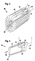
- This is shown in more detail in Figure 3 and comprises a central and cylindrical, coaxial with the longitudinal axis of the housing 30 cavity 40, from the imaginary peripheral wall, a plurality of filter walls 20 extend radially outward (in Figure 3, for clarity, only one filter wall provided with a reference numeral).
- the filter walls 20 are approximately rectangular. A front longitudinal edge of a filter wall 20 is connected to the front Longitudinal edge of the adjacent on one side of the filter wall 20, whereas the rear longitudinal edge of the filter wall 20 is connected to the corresponding rear longitudinal edge of the adjacent filter wall 20 on the other side. This results in a zigzag-like structure in the radial plan view, which forms cake-piece-like filter pockets 44 and intermediate free spaces 42 between the filter walls 20.
- Those free spaces 42 are open radially inward, radially outward, and at the upstream (ie left in FIG.) Edge, whereas at their downstream (ie, right in FIG. 2) edge they are closed by the adjoining rear edges of the filter walls 20.
- the filter pockets 44 are closed radially inward and radially outward and at their upstream (ie in FIG. 2, left) edge, whereas they are open at their downstream (that is, in FIG. 2, right) edge.
- the filter walls 20, which define the free spaces 42 and the filter pockets 44 are made of an open-pored material, for example sintered metal.
- the filter structure 38 is clamped fluid-tight in the housing 30 at its right in Figure 2 and radially outer edge in a radially inwardly extending flange 46 of the housing 30.
- the cavity 40 is closed analogously thereto at its right in Figure 2 end by a sealing wall 48.
- the two pressure sensors 22 and 24 are arranged on both sides of the sealing wall 48.
- the exhaust system 14 shown in FIG. 1 and the filter device 18 shown in FIG. 2 operate as follows: During operation of the internal combustion engine 10, soot particles are produced during the combustion of fuel. These are from the engine block 12 via the exhaust pipe 16 derived. They pass into the housing 30 of the filter device 18 via the inlet 32. There, the exhaust gas flow flows according to the arrows 50 into the free spaces 42, passes through the filter wall 20, enters the filter pockets 44 and leaves the filter device 18 via the outlet 34 Passing through the filter wall 20, soot particles present in the exhaust gas are deposited on the filter wall 20 and deposited there.
- the exhaust gas flow experiences a pressure drop in the filter device 18 not only because of the filter wall 20.
- turbulence also occurs which causes a pressure drop.
- this pressure drop is independent of the filter function of the filter device 18.
- This pressure drop is also independent of the function of the filter wall 20 or of its charge of soot particles.
- the filter device 18 when the filter device 18 is still comparatively "clean", that is to say still little soot particles are deposited in the filter device 18, a function diagnosis of the filter wall 20 can be carried out.
- a particularly small pressure drop across the filter wall 20 in the case of a "clean" filter device 18 would indicate, for example, damage, for example a hole, of the filter wall 20. This would lead to a corresponding entry in the error memory 28, which can be read by a diagnostic device. Since, due to the positioning of the two sensors 22 and 24, the loading of the filter wall 20 with soot particles can be detected comparatively precisely, regeneration measures of the filter device 18, for example a burning off of the deposited soot particles, can be initiated precisely at the required time. As a result, the reliability of the internal combustion engine 10 is increased and ultimately even the emission behavior is improved and the fuel consumption is lowered.
- FIG. 3 The illustration in FIG. 3 was already in connection with the explanation of the filter structure 38 of the filter device 18 of Figure 2 has been introduced.
- an arrangement of the two pressure sensors 22 and 24 is shown in Figure 3, which differs from the arrangement in Figure 2:
- the two pressure sensors 22 and 24 are not on both sides of the sealing wall 48, but immediately on both sides of between arranged a free space 42 and a filter bag 44 filter wall 20.
- the actual sensor tips of the two pressure sensors 22 and 24 are approximately opposite.
- FIG. 4 in which the filter structure 38 is shown only in the region of the sensors 22 and 24.
- FIG. 5 a plurality of adjacent filter bags 44 are shown. Unlike in the previous embodiments, however, not only two pressure sensors 22 and 24, but a total of three pressure sensor pairs A, B, C are present here, with the corresponding pressure sensors 22a and 24a, 22b and 24b, and 22c and 24c.
- the pressure sensors 22 and 24 of a pair A, B, C are arranged opposite each other on both sides of the filter wall, wherein in the flow direction (arrows 50) seen first the pressure sensor pair A, then with a distance the pressure sensor pair B, and then again the pressure sensor pair C is provided ,
Landscapes
- Engineering & Computer Science (AREA)
- Chemical & Material Sciences (AREA)
- Combustion & Propulsion (AREA)
- Mechanical Engineering (AREA)
- General Engineering & Computer Science (AREA)
- Chemical Kinetics & Catalysis (AREA)
- Processes For Solid Components From Exhaust (AREA)
- Filtering Of Dispersed Particles In Gases (AREA)
Description
- Die Erfindung betrifft eine Filtereinrichtung, insbesondere für eine Abgasanlage einer Brennkraftmaschine, welche Partikel aus einem Gasstrom herausfiltert und welche ein Gehäuse und mindestens eine in dem Gehäuse angeordnete Filterstruktur aufweißt, durch welche der Gasstrom hindurchtreten kann.
- Eine Filtereinrichtung der eingangsgenannten Art ist aus der DE 100 14 224 A1 bekannt. Dort ist eine Abgasanlage mit einem Vorkatalysator und einem Filter gezeigt, welche zu einer Diesel-Brennkraftmaschine gehört. Stromaufwärts vom Vorkatalysator und stromabwärts vom Filter ist jeweils ein Drucksensor vorgesehen. Diese beiden Sensoren wirken als Differenzdrucksensor und stellen ein Differenzdrucksignal bereit, welches den Differenzdruck zwischen Eingang und Ausgang der aus Vorkatalysator und Filter bestehenden Anordnung charakterisiert. Auf der Basis dieses Differenzdrucks wird ein Beladungszustand des Filters ermittelt.
- Die Kenntnis des aktuellen Beladungszustands des Filters ist für den Betrieb der Brennkraftmaschine und insbesondere der Abgasanlage sehr wichtig. Wenn der Filter einen bestimmten Beladungszustand überschreitet, steigt der Abgasgegendruck, was zu einer Beeinträchtigung des Betriebs der Brennkraftmaschine führen kann. Es ist daher bekannt, dann, wenn der Filter einen bestimmten Beladungszustand erreicht hat, diesen zu regenerieren, beispielsweise, indem die im Filter zurückgehaltenen Rußpartikel verbrannt werden. Die Regenerierung muss rechtzeitig erfolgen, da sie bei einer zu starken Beladung beeinträchtigt wird. Sie sollte aber auch nicht zu oft, erfolgen um den Kraftstoffverbrauch der Brennkraftmaschine nicht unnötig zu erhöhen.
- Die DE 101 28 936 A1 offenbart eine Filtereinrichtung mit einer Filterstruktur, die eine Vielzahl keilförmiger Filtertaschen umfasst, die von Filterwänden begrenzt werden. Als Material wird für die Filterstruktur eine offenporiges Sintermetall verwendet.
- Die vorliegende Erfindung hat die Aufgabe, eine Filtereinrichtung der eingangs genannten Art so weiter zu bilden, dass ihr Beladungszustand möglichst exakt bestimmt werden kann. Darüber hinaus wäre es wünschenswert, wenn unabhängig vom Beladungszustand der Filtereinrichtung Informationen über ihren Betriebszustand vorliegen, wenn also eine kontinuierliche Diagnose der Filtereinrichtung möglich wäre.
- Diese Aufgabe wird bei einer Filtereinrichtung der eingangs genannten Art dadurch gelöst, dass die Filterstruktur mindestens eine Filterwand aus einem offenporigen Filtermaterial umfasst, und dass mindestens zwei paarweise angeordnete Drucksensoren vorgesehen sind, von denen der eine Drucksensor wenigstens annähernd unmittelbar stromaufwärts und der andere Drucksensor wenigstens annähernd unmittelbar stromabwärts von der Filterwand angeordnet ist.
- Bei der erfindungsgemäßen Filtereinrichtung wird im wesentlichen nur jener Druckabfall erfasst, welcher beim Durchtritt des Gasstromes durch die Filterwand auftritt. Ein Druckabfall, welcher von laminaren und/oder turbulenten Strömungsverlusten im Filtergehäuse und/oder im Strömungsweg vor beziehungsweise nach dem Filtergehäuse herrührt, wird von den erfindungsgemäß angeordneten Drucksensoren nicht oder zumindest nur im geringen Umfang erfasst. Für die Funktionsfähigkeit der Filterstruktur ist jedoch nur jener Druckabfall aussagekräftig, welcher über die Filterwand hinweg auftritt. Genau dieser Druckabfall wird vorliegend erfasst.
- Bei der erfindungsgemäßen Abgasanlage ist daher eine sehr präzise Erfassung der Funktionsfähigkeit der Filtereinrichtung möglich, was nicht nur Rückschlüsse auf die Beladung der Filterstruktur mit Partikeln gestattet, sondern ganz allgemein eine Funktionsdiagnose der Filtereinrichtung ermöglicht. Besonders deutlich sind die Vorteile der erfindungsgemäßen Abgasanlage bei einer Filterstruktur, an der noch wenige Partikel abgelagert sind, da bei einer solchen "sauberen" Filterstruktur jener Druckabfall, der über die Filterwand hinweg auftritt, nur einen geringen Anteil an dem Gesamtdruckverlust in der Filtereinrichtung ausmacht.
- Vorteilhafte Weiterbildungen der Erfindung sind in Unteransprüchen angegeben.
- Zunächst wird vorgeschlagen, dass die Filterstruktur Filtertaschen, welche von Filterwänden begrenzt werden, und einen stromaufwärts von den Filterwänden gelegenen Strömungsabschnitt umfasst, der gegenüber einem stromabwärts von der Filterwand liegenden Bereich durch eine Dichtwand abgetrennt ist, und dass die beiden Drucksensoren eines Drucksensorpaares zu beiden Seiten der Dichtwand angeordnet sind. Diese Stelle ist sehr gut zugänglich, was die Integration des Drucksensorpaares in die Filtereinrichtung erleichtert. Letztlich werden hierdurch die Herstellkosten der erfindungsgemäßen Abgasanlage gesenkt.
- Ferner ist möglich, dass die Filterstruktur Filtertaschen aufweist, welche von Filterwänden begrenzt werden, und das die beiden Drucksensoren eines Drucksensorpaares zu beiden Seiten einer Filterwand einander wenigstens in etwa gegenüberliegend angeordnet sind. Hierdurch werden besonders präzise Messergebnisse erzielt.
- In Weiterbildung hierzu wird vorgeschlagen, dass die Filtereinrichtung mehrere Drucksensorpaare umfasst, und dass die Drucksensoren eines Drucksensorpaars von den Drucksensoren eines anderen Drucksensorpaares in Strömungsrichtung gesehen beabstandet sind. Dies gestattet die Messung des Druckabfalls an unterschiedlichen Stellen der Filterwand. In der Folge können Rückschlüsse auf die örtliche Beladung der Filtereinrichtung mit Partikeln gezogen werden. Hierdurch wird eine noch präzisere Erfassung des Beladungszustands der Filtereinrichtung ermöglicht.
- Besonders gut arbeitet die erfindungsgemäße Filtereinrichtung dann, wenn das Filtermaterial eine offenporige Struktur, beispielsweise ein Sintermaterial, umfasst.
- Nach folgend werden besonders bevorzugte Ausführungsbeispiele der vorliegenden Erfindung unter Bezugnahme auf die beiliegende Zeichnung näher erläutert. In der Zeichnung zeigen:
- Figur 1:
- eine schematische Darstellung einer Brennkraftmaschine mit einer Abgasanlage mit einem Partikelfilter;
- Figur 2:
- einen Schnitt durch den Partikelfilter von Figur 1 mit zwei Drucksensoren;
- Figur 3:
- eine perspektivische Darstellung einer Filterstruktur der Partikelfilters von Figur 2 mit einer alternativen Anordnung der Drucksensoren;
- Figur 4:
- eine teilweise geschnittene perspektivische Darstellung einer Filtertasche der Filterstruktur von Figur 3; und
- Figur 5:
- einen schematischen Schnitt durch einen Bereich der Filterstruktur von Figur 3 mit einer nochmals alternativen Anordnung der Drucksensoren.
- Eine Diesel-Brennkraftmaschine trägt in Figur 1 insgesamt das Bezugszeichen 10. Sie umfasst einen Motorblock 12 und ein Abgasanlage 14. Das Abgasanlage 14 wiederum umfasst ein Abgasrohr 16, in dem eine Filtereinrichtung 18 angeordnet ist. Diese umfasst eine in Figur 1 nur schematisch durch eine gestrichelte Linie angedeutete Filterwand 20. Unmittelbar stromaufwärts von der Filterwand 20 ist ein erster Drucksensor 22, und unmittelbar stromabwärts von der Filterwand 20 ein zweiter Drucksensor 24 angeordnet. Beide Drucksensoren 22 und 24 liefern Signale an eine Steuer -und Regeleinrichtung 26. Diese ist wiederum mit einem Fehlerspeicher 28 verbunden. Die Steuer- und Regeleinrichtung 26 steuert auch ganz allgemein den Betrieb der Brennkraftmaschine 10, was durch eine gestrichelte Linie angedeutet ist, welche die Steuer- und Regeleinrichtung 26 mit dem Motorblock 12 verbindet.
- Die Filtereinrichtung 18 ist in Figur 2 stärker im Detail dargestellt: Sie umfasst ein zylindrisches Gehäuse 30 mit einem Einlass 32 und einem Auslass 34. Vom Einlass 32 aus erweitert sich der Durchmesser des Gehäuses 30 konisch zu einem Zentralabschnitt 36 hin. Im Bereich des Auslasses 34 verringert sich der Durchmesser analog vom Zentralabschnitt 36 zum Auslass 34 hin.
- Im Zentralabschnitt 36 des Gehäuses 30 ist eine insgesamt zylindrische Filterstruktur 38 aufgenommen. Diese ist stärker detailliert in Figur 3 gezeigt und umfasst einen zentrischen und zylindrischen, zur Längsachse des Gehäuses 30 koaxialen Hohlraum 40, von dessen gedachter Umfangswand sich eine Vielzahl von Filterwänden 20 nach radial außen erstrecken (in Figur 3 ist aus Gründen der Übersichtlichkeit nur eine Filterwand mit einem Bezugszeichen versehen).
- Die Filterwände 20 sind insgesamt in etwa rechteckig. Ein vorderer Längsrand einer Filterwand 20 ist mit dem vorderen Längsrand der auf der einen Seite benachbarten Filterwand 20 verbunden, wohingegen der hintere Längsrand der Filterwand 20 mit dem entsprechenden hinteren Längsrand der auf der anderen Seite benachbarten Filterwand 20 verbunden ist. Hierdurch ergibt sich eine in der radialen Draufsicht zickzackartige Struktur, welche zwischen den Filterwänden 20 kuchenstückartige Filtertaschen 44 und dazwischen liegende Freiräume 42 bildet.
- Jene Freiräume 42 sind nach radial innen, nach radial außen, und am stromaufwärtigen (also in Figur linken) Rand offen, wohingegen sie an ihrem stromabwärtigen (also in Figur 2 rechten) Rand durch die aneinanderliegenden hinteren Ränder der Filterwände 20 geschlossen sind. Die Filtertaschen 44 sind dagegen radial innen und radial außen sowie an ihrem stromaufwärtigen (also in Figur 2 linken) Rand geschlossen, wohingegen sie an ihrem stromabwärtigen (also in Figur 2 rechten) Rand offen sind. Die Filterwände 20, welche die Freiräume 42 bzw. die Filtertaschen 44 begrenzen, sind aus einem offenporigen Material, beispielsweise Sintermetall.
- Die Filterstruktur 38 ist im Gehäuse 30 an ihrem in Figur 2 rechten und radial äußeren Rand in einem sich nach radial innen erstreckenden Flansch 46 des Gehäuses 30 fluiddicht verklemmt. Der Hohlraum 40 ist analog hierzu an seinem in Figur 2 rechten Ende durch eine Dichtwand 48 verschlossen. Die beiden Drucksensoren 22 und 24 sind zu beiden Seiten der Dichtwand 48 angeordnet.
- Die in Figur 1 gezeigte Abgasanlage 14 und die in Figur 2 gezeigte Filtereinrichtung 18 arbeiten folgendermaßen: Beim Betrieb der Brennkraftmaschine 10 werden bei der Verbrennung von Kraftstoff Rußpartikel erzeugt. Diese werden aus dem Motorblock 12 über das Abgasrohr 16 abgeleitet. Über den Einlass 32 gelangen sie in das Gehäuse 30 der Filtereinrichtung 18. Dort strömt der Abgasstrom entsprechend der Pfeile 50 in die Freiräume 42, tritt durch die Filterwand 20 hindurch, gelangt in die Filtertaschen 44 und verlässt die Filtereinrichtung 18 über den Auslass 34. Beim Durchtritt durch die Filterwand 20 werden im Abgas vorhandenen Rußpartikel an der Filterwand 20 abgeschieden und dort abgelagert.
- Beim Durchtritt des Abgases durch die Filterwand 20 kommt es zu einem Druckabfall. Dieser wird von den beiden Drucksensoren 22 und 24 erfasst. Die entsprechenden Signale werden zur Steuer- und Regeleinrichtung 26 geleitet. Dieser Druckabfall ist dann, wenn noch keine oder nur sehr wenig Rußpartikel in der Filtereinrichtung 18 abgeschieden sind, vergleichsweise gering. Im Laufe der Zeit werden jedoch immer mehr Rußpartikel in der Filtereinrichtung 18 abgeschieden, was zu einer allmählichen Reduzierung der Durchlässigkeit der Filterwand 20 für den Abgasstrom führt. Dies führt zu einem Anstieg des Druckabfalls über die Filterwand 20 hinweg. Dies wird von den beiden Drucksensoren 22 und 24 erfasst.
- Der Abgasstrom erfährt in der Filtereinrichtung 18 nicht nur aufgrund der Filterwand 20 einen Druckabfall. Bei der Expansion des Gasstromes vom Einlass 32 zum Zentralabschnitt 36 hin kommt es, wie durch die Pfeile 52 angedeutet ist, zu Turbulenzen, welche ebenfalls einen Druckabfall verursachen. Dieser Druckabfall ist jedoch von der Filterfunktion der Filtereinrichtung 18 unabhängig. Ebenso kommt es bei der Strömung vom Zentralabschnitt 36 zum Auslass 34 hin zu Turbulenzen, die einen Druckabfall zur Folge haben. Auch dieser Druckabfall ist von der Funktion der Filterwand 20 beziehungsweise von deren Beladung mit Rußpartikeln unabhängig.
- Durch die Anordnung der beiden Sensoren 22 und 24 unmittelbar vor beziehungsweise unmittelbar hinter der Dichtwand 48 wird im Wesentlichen nur jener Druckverlust von den beiden Drucksensoren 22 und 24 erfasst, der tatsächlich von der Drosselwirkung der Filterwand 20 herrührt. Durch die Positionierung der beiden Drucksensoren 22 und 24 erhält man daher ein für die Beladung der Filterwand 20 mit Rußpartikeln besonders charakteristisches Signal, welches von den sonstigen Strömungsverhältnissen innerhalb des Gehäuses 30 der Filtereinrichtung 18 weitgehend unbeeinflusst ist.
- Insbesondere dann, wenn die Filtereinrichtung 18 noch vergleichsweise "sauber" ist, also noch wenig Rußpartikel in der Filtereinrichtung 18 abgeschieden sind, kann eine Funktionsdiagnose der Filterwand 20 durchgeführt werden. Ein besonders geringer Druckabfall über die Filterwand 20 bei "sauberer" Filtereinrichtung 18 würde beispielsweise auf eine Beschädigung, beispielsweise ein Loch, der Filterwand 20 hindeuten. Dies würde zu einem entsprechenden Eintrag in den Fehlerspeicher 28 führen, der von einem Diagnosegerät ausgelesen werden kann. Da aufgrund der Positionierung der beiden Sensoren 22 und 24 auch die Beladung der Filterwand 20 mit Rußpartikeln vergleichsweise präzise erfasst werden kann, können Regenerationsmaßnahmen der Filtereinrichtung 18, beispielsweise ein Abbrennen der abgelagerten Rußpartikel, genau zum erforderlichen Zeitpunkt eingeleitet werden. Hierdurch wird die Betriebssicherheit der Brennkraftmaschine 10 erhöht und letztlich wird sogar das Emissionsverhalten verbessert und der Kraftstoffverbrauch gesenkt.
- Die Darstellung in Figur 3 war bereits im Zusammenhang mit der Erläuterung der Filterstruktur 38 der Filtereinrichtung 18 von Figur 2 eingeführt worden. Tatsächlich ist in Figur 3 jedoch eine Anordnung der beiden Drucksensoren 22 und 24 gezeigt, welche sich von der Anordnung in Figur 2 unterscheidet: In Figur 3 sind die beiden Drucksensoren 22 und 24 nämlich nicht beidseits der Dichtwand 48, sondern unmittelbar zu beiden Seiten einer zwischen einem Freiraum 42 und einer Filtertasche 44 liegenden Filterwand 20 angeordnet. Dabei liegen sich die eigentlichen Sensorspitzen der beiden Drucksensoren 22 und 24 in etwa gegenüber. Besonders deutlich geht dieser Sachverhalt aus Figur 4 hervor, in der die Filterstruktur 38 nur im Bereich der Sensoren 22 und 24 gezeigt ist.
- In Figur 5 sind mehrere nebeneinander liegende Filtertaschen 44 gezeigt. Anders als bei den vorhergehenden Ausführungsbeispielen sind hier jedoch nicht nur zwei Drucksensoren 22 und 24, sondern insgesamt drei Drucksensorpaare A, B, C vorhanden, mit den entsprechenden Drucksensoren 22a und 24a, 22b und 24b, sowie 22c und 24c. Die Drucksensoren 22 und 24 eines Paares A, B, C sind beidseits der Filterwand 20 einander gegenüberliegend angeordnet, wobei in Strömungsrichtung (Pfeile 50) gesehen zunächst das Drucksensorpaar A, danach mit einem Abstand das Drucksensorpaar B, und nochmals danach das Drucksensorpaar C vorgesehen ist.
- Auf diese Weise kann der Druckabfall, welcher beim Durchtritt der Strömung durch die Filterwand 20 (Pfeil 54) auftritt, an unterschiedlichen Stellen der Filterwand 20 erfasst werden, was Rückschlüsse auf die örtliche Beladung der Filterwand 20 mit Rußpartikeln 56 ermöglicht.
Claims (5)
- Filtereinrichtung (18), insbesondere für eine Abgasanlage (14) einer Brennkraftmaschine (10), welche Partikel (56) aus einem Gasstrom (50) herausfiltert und welche ein Gehäuse (30) und mindestens eine in dem Gehäuse (30) angeordnete Filterstruktur (38) aufweist, durch welche der Gasstrom (50) hindurchtreten kann, dadurch gekennzeichnet, dass die Filterstruktur (38) mindestens eine Filterwand (20) umfasst, und dass mindestens zwei paarweise angeordnete Drucksensoren (22, 24) vorgesehen sind, von denen der eine Drucksensor (22) wenigstens annähernd unmittelbar stromaufwärts und der andere Drucksensor (24) wenigstens annähernd unmittelbar stromabwärts von der Filterwand (20) angeordnet ist.
- Filtereinrichtung (18) nach Anspruch 1, dadurch gekennzeichnet, dass die Filterstruktur (38) Filtertaschen (44), welche von Filterwänden (20) begrenzt werden, und einen stromaufwärts von den Filtertaschen gelegenen Strömungsabschnitt (40) aufweist, der gegenüber einem stromabwärts von der Filterstruktur (38) liegenden Bereich durch eine Dichtwand (48) abgetrennt ist, und dass die beiden Drucksensoren (22, 24) eines Drucksensorpaares zu beiden Seiten der Dichtwand (48) angeordnet sind.
- Filtereinrichtung (18) nach einem der Ansprüche 1 oder 2, dadurch gekennzeichnet, dass die Filterstruktur (38) Filtertaschen (42) aufweist, welche von Filterwänden (20) begrenzt werden, und dass die beiden Drucksensoren (22, 24) eines Drucksensorpaares zu beiden Seiten einer zwischen Filterwand (20) einander wenigstens in etwa gegenüberliegend angeordnet sind.
- Filtereinrichtung (18) nach Anspruch 4, dadurch gekennzeichnet, dass sie mehrere Drucksensorpaare (A, B, C) umfasst, und dass die Drucksensoren (22, 24) eines Drucksensorpaars (A, B, C) von den Drucksensoren (22, 24) eines anderen Drucksensorpaares (A, B, C) in Strömungsrichtung (50) gesehen beabstandet sind.
- Filtereinrichtung (18) nach einem der vorhergehenden Ansprüche, dadurch gekennzeichnet, dass das Filtermaterial Sintermetall umfasst.
Applications Claiming Priority (2)
| Application Number | Priority Date | Filing Date | Title |
|---|---|---|---|
| DE102004001421A DE102004001421A1 (de) | 2004-01-09 | 2004-01-09 | Filtereinrichtung, insbesondere für eine Abgasanlage einer Brennkraftmaschine |
| DE102004001421 | 2004-01-09 |
Publications (2)
| Publication Number | Publication Date |
|---|---|
| EP1553268A1 EP1553268A1 (de) | 2005-07-13 |
| EP1553268B1 true EP1553268B1 (de) | 2006-08-23 |
Family
ID=34585371
Family Applications (1)
| Application Number | Title | Priority Date | Filing Date |
|---|---|---|---|
| EP04105579A Expired - Lifetime EP1553268B1 (de) | 2004-01-09 | 2004-11-08 | Filtereinrichtung, insbesondere für eine Abgasanlage einer Brennkraftmaschine |
Country Status (2)
| Country | Link |
|---|---|
| EP (1) | EP1553268B1 (de) |
| DE (2) | DE102004001421A1 (de) |
Families Citing this family (1)
| Publication number | Priority date | Publication date | Assignee | Title |
|---|---|---|---|---|
| DE102005049690A1 (de) * | 2005-10-14 | 2007-04-19 | Robert Bosch Gmbh | Temperaturvergleichmässigender Innenkanal für ein Filterelement und Filter zur Abgasnachbehandlung |
Family Cites Families (4)
| Publication number | Priority date | Publication date | Assignee | Title |
|---|---|---|---|---|
| JPH0711936A (ja) * | 1993-06-29 | 1995-01-13 | Toyota Autom Loom Works Ltd | 排気ガス浄化装置 |
| JP3598542B2 (ja) * | 1994-10-11 | 2004-12-08 | 株式会社デンソー | ディーゼル内燃機関の排気浄化装置 |
| DE10014224A1 (de) * | 1999-05-07 | 2000-11-30 | Bosch Gmbh Robert | Verfahren und Vorrichtung zur Steuerung einer Brennkraftmaschine mit einem Abgasnachbehandlungssytem |
| DE10128936A1 (de) * | 2001-06-18 | 2003-01-02 | Hjs Fahrzeugtechnik Gmbh & Co | Partikelfilter, insbesondere für Abgase von Dieselbrennkraftmaschinen |
-
2004
- 2004-01-09 DE DE102004001421A patent/DE102004001421A1/de not_active Withdrawn
- 2004-11-08 DE DE502004001259T patent/DE502004001259D1/de not_active Expired - Lifetime
- 2004-11-08 EP EP04105579A patent/EP1553268B1/de not_active Expired - Lifetime
Also Published As
| Publication number | Publication date |
|---|---|
| DE502004001259D1 (de) | 2006-10-05 |
| DE102004001421A1 (de) | 2005-08-04 |
| EP1553268A1 (de) | 2005-07-13 |
Similar Documents
| Publication | Publication Date | Title |
|---|---|---|
| EP2078143B1 (de) | Abgasreinigungsanlage für eine brennkraftmaschine | |
| EP1502016B1 (de) | Vorrichtung und verfahren zur feststellung einer fehlfunktion eines filters | |
| EP1488077B1 (de) | Gekühlte turbinenschaufel | |
| EP2206897B1 (de) | Fördereinrichtung für ein SCR-System | |
| EP2252780B1 (de) | Verfahren zum bestimmen des beladungszustandes eines in den abgasstrang einer brennkraftmaschine eingeschalteten partikelfilters sowie einrichtung zum reduzieren der partikelemission einer brennkraftmaschine | |
| DE102009043577A1 (de) | Entkoppelelement | |
| EP3298254B1 (de) | Abgasanlage mit einem gassensor, insbesondere mit einem partikelsensor | |
| DE202008003055U1 (de) | Druckminderer-Filter Anordnung mit Leckageschutz | |
| EP2401483A1 (de) | Abgasbehandlungseinrichtung und verfahren zum betreiben einer abgasbehandlungseinrichtung | |
| DE102012001314A1 (de) | Kraftstofftankentlüftungssystem für ein Kraftfahrzeug | |
| EP1490586B1 (de) | Russfilter und verfahren zur reinigung von abgasen | |
| EP1553268B1 (de) | Filtereinrichtung, insbesondere für eine Abgasanlage einer Brennkraftmaschine | |
| EP2982841B1 (de) | Verfahren zur zustandsüberwachung eines partikelfilters, abgasanlage und messvorrichtung | |
| DE102018107733A1 (de) | Verfahren und System zum Erfassen von Abgasfeinstaub | |
| EP4095363A1 (de) | Verfahren zum erkennen einer regenerationsnotwendigkeit für einen abgaspartikelfilter sowie abgasanlage | |
| DE102005018271A1 (de) | Verfahren und Vorrichtung zur Diagnose eines Schubumluftventils eines Laders r | |
| WO2009112384A2 (de) | Filtereinrichtung, insbesondere für ein abgassystem einer brennkraftmaschine | |
| DE20314408U1 (de) | Abgaspartikelfilter | |
| EP2960452B1 (de) | Abgasanlage für Brennkraftmaschinen | |
| DE102014200534A1 (de) | Zweistufige Partikelfilteranordnung | |
| DE202014100157U1 (de) | Zweistufige Partikelfilteranordnung | |
| DE102019212174B3 (de) | Verfahren und Vorrichtung zur Steuerung des Betriebs eines Partikelfilters eines Kraftfahrzeugs | |
| DE102017117140A1 (de) | Verfahren und System zum Erfassen von Feinstaub in Abgas | |
| DE102014019641A1 (de) | Abgasanlage für eine Brennkraftmaschine | |
| DE102014200535A1 (de) | Zweistufige Partikelfilteranordnung |
Legal Events
| Date | Code | Title | Description |
|---|---|---|---|
| PUAI | Public reference made under article 153(3) epc to a published international application that has entered the european phase |
Free format text: ORIGINAL CODE: 0009012 |
|
| AK | Designated contracting states |
Kind code of ref document: A1 Designated state(s): AT BE BG CH CY CZ DE DK EE ES FI FR GB GR HU IE IS IT LI LU MC NL PL PT RO SE SI SK TR |
|
| AX | Request for extension of the european patent |
Extension state: AL HR LT LV MK YU |
|
| GRAP | Despatch of communication of intention to grant a patent |
Free format text: ORIGINAL CODE: EPIDOSNIGR1 |
|
| 17P | Request for examination filed |
Effective date: 20060113 |
|
| AKX | Designation fees paid |
Designated state(s): DE FR GB IT |
|
| GRAS | Grant fee paid |
Free format text: ORIGINAL CODE: EPIDOSNIGR3 |
|
| GRAA | (expected) grant |
Free format text: ORIGINAL CODE: 0009210 |
|
| AK | Designated contracting states |
Kind code of ref document: B1 Designated state(s): DE FR GB IT |
|
| PG25 | Lapsed in a contracting state [announced via postgrant information from national office to epo] |
Ref country code: IT Free format text: LAPSE BECAUSE OF FAILURE TO SUBMIT A TRANSLATION OF THE DESCRIPTION OR TO PAY THE FEE WITHIN THE PRESCRIBED TIME-LIMIT;WARNING: LAPSES OF ITALIAN PATENTS WITH EFFECTIVE DATE BEFORE 2007 MAY HAVE OCCURRED AT ANY TIME BEFORE 2007. THE CORRECT EFFECTIVE DATE MAY BE DIFFERENT FROM THE ONE RECORDED. Effective date: 20060823 |
|
| REG | Reference to a national code |
Ref country code: GB Ref legal event code: FG4D Free format text: NOT ENGLISH |
|
| REF | Corresponds to: |
Ref document number: 502004001259 Country of ref document: DE Date of ref document: 20061005 Kind code of ref document: P |
|
| GBT | Gb: translation of ep patent filed (gb section 77(6)(a)/1977) |
Effective date: 20061129 |
|
| ET | Fr: translation filed | ||
| PLBE | No opposition filed within time limit |
Free format text: ORIGINAL CODE: 0009261 |
|
| STAA | Information on the status of an ep patent application or granted ep patent |
Free format text: STATUS: NO OPPOSITION FILED WITHIN TIME LIMIT |
|
| 26N | No opposition filed |
Effective date: 20070524 |
|
| PGFP | Annual fee paid to national office [announced via postgrant information from national office to epo] |
Ref country code: IT Payment date: 20081124 Year of fee payment: 5 |
|
| PGFP | Annual fee paid to national office [announced via postgrant information from national office to epo] |
Ref country code: FR Payment date: 20081118 Year of fee payment: 5 |
|
| PGFP | Annual fee paid to national office [announced via postgrant information from national office to epo] |
Ref country code: GB Payment date: 20081121 Year of fee payment: 5 |
|
| GBPC | Gb: european patent ceased through non-payment of renewal fee |
Effective date: 20091108 |
|
| REG | Reference to a national code |
Ref country code: FR Ref legal event code: ST Effective date: 20100730 |
|
| PG25 | Lapsed in a contracting state [announced via postgrant information from national office to epo] |
Ref country code: FR Free format text: LAPSE BECAUSE OF NON-PAYMENT OF DUE FEES Effective date: 20091130 |
|
| PG25 | Lapsed in a contracting state [announced via postgrant information from national office to epo] |
Ref country code: GB Free format text: LAPSE BECAUSE OF NON-PAYMENT OF DUE FEES Effective date: 20091108 |
|
| PG25 | Lapsed in a contracting state [announced via postgrant information from national office to epo] |
Ref country code: IT Free format text: LAPSE BECAUSE OF NON-PAYMENT OF DUE FEES Effective date: 20091108 |
|
| PGFP | Annual fee paid to national office [announced via postgrant information from national office to epo] |
Ref country code: DE Payment date: 20110125 Year of fee payment: 7 |
|
| REG | Reference to a national code |
Ref country code: DE Ref legal event code: R119 Ref document number: 502004001259 Country of ref document: DE Effective date: 20120601 |
|
| PG25 | Lapsed in a contracting state [announced via postgrant information from national office to epo] |
Ref country code: DE Free format text: LAPSE BECAUSE OF NON-PAYMENT OF DUE FEES Effective date: 20120601 |