EP1553199A1 - Teile für fluid - Google Patents
Teile für fluid Download PDFInfo
- Publication number
- EP1553199A1 EP1553199A1 EP03741293A EP03741293A EP1553199A1 EP 1553199 A1 EP1553199 A1 EP 1553199A1 EP 03741293 A EP03741293 A EP 03741293A EP 03741293 A EP03741293 A EP 03741293A EP 1553199 A1 EP1553199 A1 EP 1553199A1
- Authority
- EP
- European Patent Office
- Prior art keywords
- fluid handling
- handling part
- fluid
- valve
- cap nut
- Prior art date
- Legal status (The legal status is an assumption and is not a legal conclusion. Google has not performed a legal analysis and makes no representation as to the accuracy of the status listed.)
- Withdrawn
Links
- 239000012530 fluid Substances 0.000 title claims abstract description 44
- 229910045601 alloy Inorganic materials 0.000 claims abstract description 16
- 239000000956 alloy Substances 0.000 claims abstract description 16
- 229910052751 metal Inorganic materials 0.000 claims abstract description 8
- 239000002184 metal Substances 0.000 claims abstract description 8
- 239000012535 impurity Substances 0.000 claims abstract description 6
- 230000008878 coupling Effects 0.000 claims description 22
- 238000010168 coupling process Methods 0.000 claims description 22
- 238000005859 coupling reaction Methods 0.000 claims description 22
- 230000007797 corrosion Effects 0.000 description 17
- 238000005260 corrosion Methods 0.000 description 17
- 239000000463 material Substances 0.000 description 7
- 235000013305 food Nutrition 0.000 description 5
- 238000004519 manufacturing process Methods 0.000 description 5
- 150000003841 chloride salts Chemical class 0.000 description 3
- 150000003839 salts Chemical class 0.000 description 3
- 238000010586 diagram Methods 0.000 description 2
- 230000001747 exhibiting effect Effects 0.000 description 2
- 230000002035 prolonged effect Effects 0.000 description 2
- 238000009877 rendering Methods 0.000 description 2
- 229910001220 stainless steel Inorganic materials 0.000 description 2
- 239000002253 acid Substances 0.000 description 1
- 229910052782 aluminium Inorganic materials 0.000 description 1
- XAGFODPZIPBFFR-UHFFFAOYSA-N aluminium Chemical compound [Al] XAGFODPZIPBFFR-UHFFFAOYSA-N 0.000 description 1
- 229920005549 butyl rubber Polymers 0.000 description 1
- 239000003814 drug Substances 0.000 description 1
- 230000000694 effects Effects 0.000 description 1
- 230000002093 peripheral effect Effects 0.000 description 1
- 239000004810 polytetrafluoroethylene Substances 0.000 description 1
- 229920001343 polytetrafluoroethylene Polymers 0.000 description 1
- 238000007789 sealing Methods 0.000 description 1
Images

Classifications
-
- F—MECHANICAL ENGINEERING; LIGHTING; HEATING; WEAPONS; BLASTING
- F16—ENGINEERING ELEMENTS AND UNITS; GENERAL MEASURES FOR PRODUCING AND MAINTAINING EFFECTIVE FUNCTIONING OF MACHINES OR INSTALLATIONS; THERMAL INSULATION IN GENERAL
- F16K—VALVES; TAPS; COCKS; ACTUATING-FLOATS; DEVICES FOR VENTING OR AERATING
- F16K27/00—Construction of housing; Use of materials therefor
- F16K27/02—Construction of housing; Use of materials therefor of lift valves
- F16K27/0236—Diaphragm cut-off apparatus
-
- C—CHEMISTRY; METALLURGY
- C22—METALLURGY; FERROUS OR NON-FERROUS ALLOYS; TREATMENT OF ALLOYS OR NON-FERROUS METALS
- C22C—ALLOYS
- C22C38/00—Ferrous alloys, e.g. steel alloys
- C22C38/001—Ferrous alloys, e.g. steel alloys containing N
-
- C—CHEMISTRY; METALLURGY
- C22—METALLURGY; FERROUS OR NON-FERROUS ALLOYS; TREATMENT OF ALLOYS OR NON-FERROUS METALS
- C22C—ALLOYS
- C22C38/00—Ferrous alloys, e.g. steel alloys
- C22C38/18—Ferrous alloys, e.g. steel alloys containing chromium
- C22C38/40—Ferrous alloys, e.g. steel alloys containing chromium with nickel
- C22C38/42—Ferrous alloys, e.g. steel alloys containing chromium with nickel with copper
-
- C—CHEMISTRY; METALLURGY
- C22—METALLURGY; FERROUS OR NON-FERROUS ALLOYS; TREATMENT OF ALLOYS OR NON-FERROUS METALS
- C22C—ALLOYS
- C22C38/00—Ferrous alloys, e.g. steel alloys
- C22C38/18—Ferrous alloys, e.g. steel alloys containing chromium
- C22C38/40—Ferrous alloys, e.g. steel alloys containing chromium with nickel
- C22C38/44—Ferrous alloys, e.g. steel alloys containing chromium with nickel with molybdenum or tungsten
-
- F—MECHANICAL ENGINEERING; LIGHTING; HEATING; WEAPONS; BLASTING
- F16—ENGINEERING ELEMENTS AND UNITS; GENERAL MEASURES FOR PRODUCING AND MAINTAINING EFFECTIVE FUNCTIONING OF MACHINES OR INSTALLATIONS; THERMAL INSULATION IN GENERAL
- F16K—VALVES; TAPS; COCKS; ACTUATING-FLOATS; DEVICES FOR VENTING OR AERATING
- F16K27/00—Construction of housing; Use of materials therefor
-
- F—MECHANICAL ENGINEERING; LIGHTING; HEATING; WEAPONS; BLASTING
- F16—ENGINEERING ELEMENTS AND UNITS; GENERAL MEASURES FOR PRODUCING AND MAINTAINING EFFECTIVE FUNCTIONING OF MACHINES OR INSTALLATIONS; THERMAL INSULATION IN GENERAL
- F16L—PIPES; JOINTS OR FITTINGS FOR PIPES; SUPPORTS FOR PIPES, CABLES OR PROTECTIVE TUBING; MEANS FOR THERMAL INSULATION IN GENERAL
- F16L19/00—Joints in which sealing surfaces are pressed together by means of a member, e.g. a swivel nut, screwed on, or into, one of the joint parts
- F16L19/08—Joints in which sealing surfaces are pressed together by means of a member, e.g. a swivel nut, screwed on, or into, one of the joint parts with metal rings which bite into the wall of the pipe
- F16L19/10—Joints in which sealing surfaces are pressed together by means of a member, e.g. a swivel nut, screwed on, or into, one of the joint parts with metal rings which bite into the wall of the pipe the profile of the ring being altered
- F16L19/103—Joints in which sealing surfaces are pressed together by means of a member, e.g. a swivel nut, screwed on, or into, one of the joint parts with metal rings which bite into the wall of the pipe the profile of the ring being altered with more than one ring per pipe end being used
-
- F—MECHANICAL ENGINEERING; LIGHTING; HEATING; WEAPONS; BLASTING
- F16—ENGINEERING ELEMENTS AND UNITS; GENERAL MEASURES FOR PRODUCING AND MAINTAINING EFFECTIVE FUNCTIONING OF MACHINES OR INSTALLATIONS; THERMAL INSULATION IN GENERAL
- F16L—PIPES; JOINTS OR FITTINGS FOR PIPES; SUPPORTS FOR PIPES, CABLES OR PROTECTIVE TUBING; MEANS FOR THERMAL INSULATION IN GENERAL
- F16L58/00—Protection of pipes or pipe fittings against corrosion or incrustation
- F16L58/18—Protection of pipes or pipe fittings against corrosion or incrustation specially adapted for pipe fittings
- F16L58/184—Protection of pipes or pipe fittings against corrosion or incrustation specially adapted for pipe fittings for joints in which sealing surfaces are pressed together by means of a member, e.g. a swivel nut, screwed on or into one of the joint parts
Definitions
- the present invention relates to fluid handling parts, such as couplings for use in piping systems and valves or like fluid control devices for use in fluid control apparatus, and more particularly to fluid handling parts suitable for use in apparatus for manufacturing pharmaceuticals and foods.
- Fluid handing parts are generally used as parts for universal use in fluid control apparatus and various piping systems.
- Conventional fluid handling parts include metal parts which are generally made of SUS316. Sophisticated characteristics as to corrosion resistance to chlorides, acid resistance, high strength, etc. are required of these fluid handling parts in accordance with the application and the environment wherein they are used.
- An object of the present invention is to provide a fluid handling part which is improved in corrosion resistance while retaining the other properties.
- the present invention provides a valve, coupling or like fluid handling part for use in piping and fluid control devices which is composed of a plurality of components, the plurality of components including a specified metal member having a surface exposed on an exterior of the fluid handling part, the fluid handling part being characterized in that the metal member is made of an alloy comprising, in % by weight, 0.001 to 0.01% of C, up to 5% of Si, up to 2% of Mn, up to 0.03% of P, up to 100 ppm of S, up to 50 ppm of O, 18 to 25% of Cr, 15 to 25% of Ni, 4.5 to 7.0% of Mo, 0.5 to 3.0% of Cu, 0.1 to 0.3% of N, and the balance substantially Fe and other inevitable impurities.
- the metal member is made of an alloy comprising, in % by weight, 0.001 to 0.01% of C, up to 5% of Si, up to 2% of Mn, up to 0.03% of P, up to 100 ppm of S, up to 50 ppm of O
- the material used for the fluid handling part is an alloy comprising, in % by weight, 0.001 to 0.01% of C, up to 5% of Si, up to 2% of Mn, up to 0.03% of P, up to 100 ppm of S, up to 50 ppm of O, 18 to 25% of Cr, 15 to 25% of Ni, 4.5 to 7.0% of Mo, 0.5 to 3.0% of Cu, 0.1 to 0.3% of N, and the balance substantially Fe and other inevitable impurities. Accordingly, the part can be improved in corrosion resistance without entailing a reduction in strength and in hardness which has been a disadvantage resulting from the improvement in corrosion resistance.
- a preferred embodiment of fluid handling part is a valve comprising a body, an actuator, a diaphragm, and bolts for fastening these components together.
- the bolts are made of the above alloy.
- the actuator is, for example, an assembly of bonnet, valve stem, piston, casing and handle.
- the actuator is an assembly comprising a bonnet, valve stem, valve disk holder, spring, upper and lower casings and handle.
- Each of the actuator and the diaphragm constituting the valve then becomes easy to replace, with the body of the valve incorporated in a piping system.
- the valve is also easy to assemble.
- the bolts can be prevented from corrosion and can therefore be precluded from breaking owing to corrosion, rendering the fluid handling part serviceable for a prolonged period of time.
- at least one of components other than the bolt i.e., at least one of the body, handle and actuator may of course be made of the above alloy.
- fluid handling part is a flareless pipe coupling which comprises a tubular body (coupling member) having an externally threaded end portion, a front and a back ring fitted around a pipe, and a cap nut for tightening up the two rings as held between the threaded portion and the nut, the cap nut being made of the alloy described above.
- the pipe coupling thus constructed produces a fluid-tight sealing effect, while the pipe coupling is easy to assemble.
- the cap nut is prevented from corrosion and can therefore be precluded from breaking owing to corrosion, rendering the fluid handling part usable for a prolonged period of time.
- the pipe coupling may comprise a first and a second tubular coupling member to be butted against each other with a gasket interposed therebetween, and a cap nut for fastening the two coupling members together.
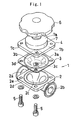
- FIG. 1 shows a first embodiment of fluid handling part of the invention.
- the fluid handling part 1 of the embodiment is a valve, which comprises a body 2 having a fluid inlet channel 2a and a fluid outlet channel 2b, a diaphragm 3 for opening or closing the fluid channels 2a, 2b of the body 2, an actuator 4 having a handle 6 and adapted to move the diaphragm 3 between an open position and a closed position, and bolts 5 for fastening these components 2, 3, 4 together.
- the body 2 has a circular cavity 2c formed in its center and facing upward.
- the fluid inlet channel 2a and the fluid outlet channel 2b are opened to the cavity 2c.
- the body 2 has around the cavity 2c an opening edge portion 2d which is square.
- Bolt holes 2e are formed respectively in the four corners of the edge portion 2d
- the diaphragm 3 comprises a square diagram 3a having an end of a suspending member 3c embedded therein, and a circular diaphragm 3b provided in intimate contact with the upper surface of the square diaphragm 3a
- the square diaphragm 3a has four corners extending outward beyond the circular diaphragm 3b and provided with respective bolt holes 3d.
- the actuator 4 comprises a hollow cylindrical bonnet 7 having a top wall 7a, and a square flange 7b provided at the lower end of the bonnet 7 and having internally threaded portions 7a in the respective four corners thereof.
- the body 2, the diaphragm 3 and the actuator 4 are lapped over one another so that the square diagram 3a of the diaphragm 3 has its outer peripheral portion held between the flange 7b of the bonnet 7 and the opening edge portion 2d of the body 2.
- the bolts 5 are inserted through the bolts holes 2e of the body 2 and the bolt holes 3d of the diaphragm 3 from below the body 2 and screwed into the internally threaded portions 7c of the bonnet 7 of the actuator 4, whereby the valve 1 is assembled.
- the body 2 is made of SUS316
- the square diaphragm 3a is made of PTFE
- the circular diaphragm 3b is made of butyl rubber
- the actuator 4 is made of aluminum
- the bolts 5 are made of an alloy comprising, in % by weight, 0.001 to 0.01% of C, up to 5% of Si, up to 2% of Mn, up to 0.03% of P, up to 100 ppm of S, up to 50 ppm of O, 18 to 25% of Cr, 15 to 25% of Ni, 4.5 to 7.0% of Mo, 0.5 to 3.0% of Cu, 0.1 to 0.3% of N, and the balance substantially Fe and other inevitable impurities.
- the alloy for use as the material of the bolts has high corrosion resistance to chlorides and is in no way inferior to common stainless steels such as SUS316 in properties other than corrosion resistance.
- the alloy has about 1.5 times the proof stress of SUS316. Accordingly, the valve 1 available remains unimpaired in these other properties while additionally exhibiting the advantage that the corrosion of the exposed surfaces of bolts 5 is prevented. For this reason, the valve 1 is readily usable in food or pharmaceutical manufacturing apparatus wherein solutions of high salt concentration are handled.
- the same alloy as the material of the bolts is of course usable also for the body 2 and the actuator 4.
- the actuator 4 can be changed over from the normally open type to the normally closed type, and vice versa.
- the illustrated actuator 4, which is of the manual type can be replaced by an actuator which has a joint opening for an air inlet pipe and which is automatically openable or closable.
- the illustrated body 2, which is of the clamp connection type, can be replaced by the flange connection type.
- the actuator 4 and the diaphragm 3 can be replaced even with the body 2 incorporated in a piping system, with the result that the piping system including the valve 1, and the apparatus concerned can be disassembled and assembled easily.
- FIGS. 2 and 3 show a second embodiment of fluid handling part of the present invention.
- the left-hand side of these drawings will be referred to as “front,” and the right-hand side thereof as “rear.”
- the fluid handling part 30 of this embodiment is a pipe joint, which comprises a tubular body (coupling member) 31 for a pipe 32 to be inserted in through the rear end thereof, a front ring 33 and a back ring 34 which are to be fitted around the pipe 32 projecting from the rear end of the body 31, and a cap nut 35 for tightening up the front and back rings 33, 34 to fix the pipe 32 to the body 31.
- the body 31 has an outer flange 36 formed around the outer periphery of an intermediate portion thereof and externally threaded portions 37, 38 respectively at front and rear end portions thereof.
- the inner periphery of the body 31 has a large-diameter rear-end portion 31a slightly larger than the front portion of the body inner periphery.
- the body 31 has a tapered face 31b formed on the inner periphery of its rear end and tapered toward the front.
- the cap nut 35 is provided at the front-end side thereof with an internally threaded portion 35a, which is screwed on the externally threaded rear-end portion 38 of the body 31.
- the cap nut 35 has an inner flange 35b at the rear end thereof.
- the front ring 33 is provided on its outer periphery with a tapered face 33a shaped in conformity with the shape of the tapered face 31b at the rear end of the body 31.
- the front ring 33 has an annular recess 33b formed at the inner periphery of its rear end and tapered toward the front.
- the back ring 34 is provided at its front end with an annular projection 34a tapered toward the front and fittable into the recess 33b of the front ring 33.
- the front face of the inner flange 35b of the cap nut 35 comes into bearing contact with the rear face of the back ring 34, advancing the back ring 34, whereby the projection 34a of the back ring 34 is fitted into the recess 33b of the front ring 33.
- the front ring 33 is moved forward along with the back ring 34 and has its front end brought into contact with the tapered face 31b of the body 31.
- the cap nut 35 is further tightened up, the respective front ends of the front ring and the back ring 34 are deformed inward, caused to bite into the pipe 31 and firmly pressed against the pipe 32.
- the materials of the members 31, 33, 34, 35, the body 31, front ring 33 and back ring 34 are made of SUS316
- the cap nut 35 is made of an alloy comprising, in % by weight, 0. 001 to 0.01% of C, up to 5% of Si, up to 2% of Mn, up to 0.03% of P, up to 100 ppm of S, up to 50 ppm of O, 18 to 25% of Cr, 15 to 25% of Ni, 4.5 to 7.0% of Mo, 0.5 to 3.0% of Cu, 0.1 to 0.3% of N, and the balance substantially Fe and other inevitable impurities.
- the alloy for use as the material for the cap nut 35 has high corrosion resistance to chlorides and is in no way inferior to common stainless steels such as SUS316 in properties other than corrosion resistance.
- the alloy has about 1.5 times the proof stress of SUS316. Accordingly, the pipe coupling 30 available remains unimpaired in these other properties while additionally exhibiting the advantage that the corrosion of the exposed surface of cap nut 35 is prevented. For this reason, the pipe coupling 30 is readily usable in food or pharmaceutical manufacturing apparatus wherein solutions of high salt concentration are handled.
- the same alloy as the material of the cap nut 35 is of course usable also for the body 31 when so required.
- the fluid handling part of the invention has high corrosion resistance, is usable as a coupling for use in piping systems and as a valve for use in fluid control apparatus, is suitable especially for use in pharmaceutical or food manufacturing apparatus.
Landscapes
- Engineering & Computer Science (AREA)
- Chemical & Material Sciences (AREA)
- Mechanical Engineering (AREA)
- General Engineering & Computer Science (AREA)
- Materials Engineering (AREA)
- Metallurgy (AREA)
- Organic Chemistry (AREA)
- Valve Housings (AREA)
- Connection Of Plates (AREA)
- Joints With Pressure Members (AREA)
Applications Claiming Priority (3)
| Application Number | Priority Date | Filing Date | Title |
|---|---|---|---|
| JP2002199906 | 2002-07-09 | ||
| JP2002199906A JP2004043845A (ja) | 2002-07-09 | 2002-07-09 | 流体部品 |
| PCT/JP2003/008696 WO2004005569A1 (ja) | 2002-07-09 | 2003-07-09 | 流体部品 |
Publications (2)
| Publication Number | Publication Date |
|---|---|
| EP1553199A1 true EP1553199A1 (de) | 2005-07-13 |
| EP1553199A4 EP1553199A4 (de) | 2005-08-31 |
Family
ID=30112488
Family Applications (1)
| Application Number | Title | Priority Date | Filing Date |
|---|---|---|---|
| EP03741293A Withdrawn EP1553199A4 (de) | 2002-07-09 | 2003-07-09 | Teile für fluid |
Country Status (8)
| Country | Link |
|---|---|
| US (1) | US20060102868A1 (de) |
| EP (1) | EP1553199A4 (de) |
| JP (1) | JP2004043845A (de) |
| CN (1) | CN1320152C (de) |
| AU (1) | AU2003281315A1 (de) |
| CA (1) | CA2491967A1 (de) |
| IL (1) | IL166126A0 (de) |
| WO (1) | WO2004005569A1 (de) |
Family Cites Families (24)
| Publication number | Priority date | Publication date | Assignee | Title |
|---|---|---|---|---|
| US2091874A (en) * | 1936-05-21 | 1937-08-31 | Hughes Tool Co | Flow bean indicator |
| US2701149A (en) * | 1952-04-29 | 1955-02-01 | Kreidel Hans | Compressed wedge pipe coupling |
| BE795528A (fr) * | 1971-02-16 | 1973-06-18 | Crawford Cullen B | Raccord de jonction de tubes |
| US3767164A (en) * | 1971-07-01 | 1973-10-23 | Milwaukee Valve Co Inc | Throttle-shutoff valve |
| US3888521A (en) * | 1973-07-11 | 1975-06-10 | Parker Hannifin Corp | Tube coupling and ferrule therefor |
| JPS58148387U (ja) * | 1982-03-30 | 1983-10-05 | 富士金属工作株式会社 | 管継手 |
| SE441455B (sv) * | 1983-10-21 | 1985-10-07 | Avesta Ab | Stal av austenitisk typ |
| US4705062A (en) * | 1987-02-18 | 1987-11-10 | Cameron Iron Works, Inc. | Choke and improved needle tip therefor |
| JPH0694057B2 (ja) * | 1987-12-12 | 1994-11-24 | 新日本製鐵株式會社 | 耐海水性に優れたオーステナイト系ステンレス鋼の製造方法 |
| US5110544A (en) * | 1989-11-29 | 1992-05-05 | Nippon Steel Corporation | Stainless steel exhibiting excellent anticorrosion property for use in engine exhaust systems |
| US5135269A (en) * | 1990-07-09 | 1992-08-04 | Cajon Company | Tube coupling |
| DE4038539C1 (de) * | 1990-12-03 | 1992-04-30 | Parker-Ermeto Gmbh, 4800 Bielefeld, De | |
| US5152500A (en) * | 1991-03-27 | 1992-10-06 | Asepco, Inc. | Aseptic valve construction |
| DE4311278A1 (de) * | 1993-04-06 | 1994-10-13 | Schwer Gmbh Edelstahl Fittings | Rohrverbindung mit einem Schneidring |
| KR100259557B1 (ko) * | 1993-10-20 | 2000-06-15 | 고지마 마타오 | 고순도가스용 스테인레스강 |
| US5586745A (en) * | 1995-06-05 | 1996-12-24 | The United States Of America As Represented By The United States Department Of Energy | Value for controlling flow of cryogenic fluid |
| JP2936316B2 (ja) * | 1996-02-28 | 1999-08-23 | 株式会社杉山商事 | 管継手の後方環体の製造方法 |
| US6039361A (en) * | 1998-01-21 | 2000-03-21 | Mwm Distributors | Plumbing compression fitting for connecting ends of pipe |
| US5909747A (en) * | 1998-04-03 | 1999-06-08 | American Meter Company | Radial flow diaphragm valve |
| JP2000257781A (ja) * | 1999-03-05 | 2000-09-19 | Kubota Corp | 軟質管用管継手 |
| JP2002069590A (ja) * | 2000-09-01 | 2002-03-08 | Nkk Corp | 高耐食クラッド鋼 |
| JP2002089724A (ja) * | 2000-09-12 | 2002-03-27 | Kitz Corp | シール部材およびそれを用いたバルブ |
| US6345806B1 (en) * | 2000-11-13 | 2002-02-12 | Jiun-Yan Chen | Foot-actuated faucet |
| US6576068B2 (en) * | 2001-04-24 | 2003-06-10 | Ati Properties, Inc. | Method of producing stainless steels having improved corrosion resistance |
-
2002
- 2002-07-09 JP JP2002199906A patent/JP2004043845A/ja active Pending
-
2003
- 2003-07-09 WO PCT/JP2003/008696 patent/WO2004005569A1/ja not_active Ceased
- 2003-07-09 US US10/519,675 patent/US20060102868A1/en not_active Abandoned
- 2003-07-09 CA CA002491967A patent/CA2491967A1/en not_active Abandoned
- 2003-07-09 EP EP03741293A patent/EP1553199A4/de not_active Withdrawn
- 2003-07-09 AU AU2003281315A patent/AU2003281315A1/en not_active Abandoned
- 2003-07-09 CN CNB038161826A patent/CN1320152C/zh not_active Expired - Fee Related
-
2004
- 2004-12-27 IL IL16612604A patent/IL166126A0/xx unknown
Also Published As
| Publication number | Publication date |
|---|---|
| WO2004005569A8 (ja) | 2005-06-16 |
| US20060102868A1 (en) | 2006-05-18 |
| WO2004005569A1 (ja) | 2004-01-15 |
| EP1553199A4 (de) | 2005-08-31 |
| CN1320152C (zh) | 2007-06-06 |
| IL166126A0 (en) | 2006-01-15 |
| CA2491967A1 (en) | 2004-01-15 |
| CN1671875A (zh) | 2005-09-21 |
| AU2003281315A1 (en) | 2004-01-23 |
| JP2004043845A (ja) | 2004-02-12 |
Similar Documents
| Publication | Publication Date | Title |
|---|---|---|
| US6419237B1 (en) | Spring compression seal | |
| US5013009A (en) | Top entry valve | |
| JP5204550B2 (ja) | メタルガスケット | |
| EP0246109A2 (de) | Ventil | |
| US7243903B2 (en) | Valve diaphragm with a compression restraining ring, and valve including same | |
| US20170234464A1 (en) | Crimp connection with one or more crimping elements | |
| TW202104782A (zh) | 隔膜及隔膜閥 | |
| US20060102867A1 (en) | Fluid controller | |
| WO2006107005A1 (ja) | バタフライバルブ | |
| EP1536030A1 (de) | Rohrverbindung | |
| EP1536029A1 (de) | TEILE FüR FLUID | |
| US20060102868A1 (en) | Parts for fluid | |
| EP0392992B1 (de) | Reingas-Ventil mit Metall-auf-Metall-Dichtung | |
| US20040188955A1 (en) | Ring-shaped metal gasket | |
| US3069128A (en) | Butterfly valve seal construction | |
| US10215290B2 (en) | Plug with attachable upper trunnion | |
| GB2224335A (en) | Valve | |
| CN211449675U (zh) | 一种快速起闭密封闸阀 | |
| US3471122A (en) | Top entry valve | |
| JPH07151256A (ja) | 防食弁 | |
| US20200310068A1 (en) | Sanitary in-line sight glass assembly | |
| US12546416B1 (en) | Toothed gripper with variable height teeth | |
| DE3839604A1 (de) | Verbindung | |
| KR20050017006A (ko) | 유체 부품 | |
| JP4080985B2 (ja) | 弁装置 |
Legal Events
| Date | Code | Title | Description |
|---|---|---|---|
| PUAI | Public reference made under article 153(3) epc to a published international application that has entered the european phase |
Free format text: ORIGINAL CODE: 0009012 |
|
| 17P | Request for examination filed |
Effective date: 20050111 |
|
| AK | Designated contracting states |
Kind code of ref document: A1 Designated state(s): AT BE BG CH CY CZ DE DK EE ES FI FR GB GR HU IE IT LI LU MC NL PT RO SE SI SK TR |
|
| AX | Request for extension of the european patent |
Extension state: AL LT LV MK |
|
| A4 | Supplementary search report drawn up and despatched |
Effective date: 20050718 |
|
| RIC1 | Information provided on ipc code assigned before grant |
Ipc: 7F 16K 25/00 B Ipc: 7C 22C 38/46 B Ipc: 7C 22C 38/44 B Ipc: 7F 16K 27/00 B Ipc: 7F 16L 19/08 B Ipc: 7C 22C 38/58 B Ipc: 7C 22C 38/00 A |
|
| DAX | Request for extension of the european patent (deleted) | ||
| RBV | Designated contracting states (corrected) |
Designated state(s): CH DE FR GB IT LI NL |
|
| RIN1 | Information on inventor provided before grant (corrected) |
Inventor name: CHIKAIKE, YOSHIAKI,C/O FUJIKIN INCORPORATED Inventor name: SOGAO, MASAHIKO,C/O FUJIKIN INCORPORATED Inventor name: DAIDO, KUNIHIKO,C/O FUJIKIN INCORPORATED Inventor name: SATO, JYUNJI,C/O FUJIKIN INCORPORATED Inventor name: MORIMOTO, AKIHIRO,C/O FUJIKIN INCORPORATED Inventor name: YOSHIKAWA, KAZUHIRO,C/O FUJIKIN INCORPORATED Inventor name: SOGABE, KYOTA,C/O FUJIKIN INCORPORATED Inventor name: KITA, TOSHIO,C/O FUJIKIN INCORPORATED Inventor name: MIYAGAWA, HIDEYUKI,C/O FUJIKIN INCORPORATED Inventor name: SUETSUGU, KAZUHIRO,C/O NIP.ST.&SUM.STAIN.ST.CORP. Inventor name: MATSUHASHI, RYO,C/O NIPPON STEEL CORPORATION |
|
| STAA | Information on the status of an ep patent application or granted ep patent |
Free format text: STATUS: THE APPLICATION IS DEEMED TO BE WITHDRAWN |
|
| 18D | Application deemed to be withdrawn |
Effective date: 20080201 |