EP1552981A1 - Seat construction - Google Patents
Seat construction Download PDFInfo
- Publication number
- EP1552981A1 EP1552981A1 EP03764216A EP03764216A EP1552981A1 EP 1552981 A1 EP1552981 A1 EP 1552981A1 EP 03764216 A EP03764216 A EP 03764216A EP 03764216 A EP03764216 A EP 03764216A EP 1552981 A1 EP1552981 A1 EP 1552981A1
- Authority
- EP
- European Patent Office
- Prior art keywords
- frame
- backward
- seat
- flat spring
- seat back
- Prior art date
- Legal status (The legal status is an assumption and is not a legal conclusion. Google has not performed a legal analysis and makes no representation as to the accuracy of the status listed.)
- Granted
Links
Images


Classifications
-
- B—PERFORMING OPERATIONS; TRANSPORTING
- B60—VEHICLES IN GENERAL
- B60N—SEATS SPECIALLY ADAPTED FOR VEHICLES; VEHICLE PASSENGER ACCOMMODATION NOT OTHERWISE PROVIDED FOR
- B60N2/00—Seats specially adapted for vehicles; Arrangement or mounting of seats in vehicles
- B60N2/02—Seats specially adapted for vehicles; Arrangement or mounting of seats in vehicles the seat or part thereof being movable, e.g. adjustable
- B60N2/22—Seats specially adapted for vehicles; Arrangement or mounting of seats in vehicles the seat or part thereof being movable, e.g. adjustable the back-rest being adjustable
-
- A—HUMAN NECESSITIES
- A47—FURNITURE; DOMESTIC ARTICLES OR APPLIANCES; COFFEE MILLS; SPICE MILLS; SUCTION CLEANERS IN GENERAL
- A47C—CHAIRS; SOFAS; BEDS
- A47C7/00—Parts, details, or accessories of chairs or stools
- A47C7/02—Seat parts
- A47C7/14—Seat parts of adjustable shape; elastically mounted ; adaptable to a user contour or ergonomic seating positions
-
- B—PERFORMING OPERATIONS; TRANSPORTING
- B60—VEHICLES IN GENERAL
- B60N—SEATS SPECIALLY ADAPTED FOR VEHICLES; VEHICLE PASSENGER ACCOMMODATION NOT OTHERWISE PROVIDED FOR
- B60N2/00—Seats specially adapted for vehicles; Arrangement or mounting of seats in vehicles
- B60N2/02—Seats specially adapted for vehicles; Arrangement or mounting of seats in vehicles the seat or part thereof being movable, e.g. adjustable
- B60N2/04—Seats specially adapted for vehicles; Arrangement or mounting of seats in vehicles the seat or part thereof being movable, e.g. adjustable the whole seat being movable
- B60N2/06—Seats specially adapted for vehicles; Arrangement or mounting of seats in vehicles the seat or part thereof being movable, e.g. adjustable the whole seat being movable slidable
-
- B—PERFORMING OPERATIONS; TRANSPORTING
- B60—VEHICLES IN GENERAL
- B60N—SEATS SPECIALLY ADAPTED FOR VEHICLES; VEHICLE PASSENGER ACCOMMODATION NOT OTHERWISE PROVIDED FOR
- B60N2/00—Seats specially adapted for vehicles; Arrangement or mounting of seats in vehicles
- B60N2/24—Seats specially adapted for vehicles; Arrangement or mounting of seats in vehicles for particular purposes or particular vehicles
- B60N2/42—Seats specially adapted for vehicles; Arrangement or mounting of seats in vehicles for particular purposes or particular vehicles the seat constructed to protect the occupant from the effect of abnormal g-forces, e.g. crash or safety seats
- B60N2/427—Seats or parts thereof displaced during a crash
-
- B—PERFORMING OPERATIONS; TRANSPORTING
- B60—VEHICLES IN GENERAL
- B60N—SEATS SPECIALLY ADAPTED FOR VEHICLES; VEHICLE PASSENGER ACCOMMODATION NOT OTHERWISE PROVIDED FOR
- B60N2/00—Seats specially adapted for vehicles; Arrangement or mounting of seats in vehicles
- B60N2/70—Upholstery springs ; Upholstery
- B60N2/7011—Upholstery springs ; Upholstery of substantially two-dimensional shape, e.g. hammock-like, plastic shells, fabrics
Landscapes
- Engineering & Computer Science (AREA)
- Aviation & Aerospace Engineering (AREA)
- Transportation (AREA)
- Mechanical Engineering (AREA)
- Seats For Vehicles (AREA)
- Chair Legs, Seat Parts, And Backrests (AREA)
Abstract
Description
- The present invention relates to a seat structure, more in detail, to a seat structure suitable for transportation machines such as a plane, a train, a ship, a fork lift, an automobile and the like, or for various chairs and a wheel chair used inside or outside of a building.
- In a seat used in a plane, a train, a ship, an automobile and the like, a seat back is required to be tilted not more than necessity when a large impact force is applied upon a head-on collision or a rear-end collision. When a seat back tilts too deep, a passenger on a back seat may be injured. It is also conceivable that the leg is caught in a steering, which may cause a risk to receive an injury by a load on the waist or the like or receive an injury on the head by baggage put on the back seat. Therefore, it is required to restrain a tilt of a seat back to restrain displacement of the human body by pushing the passenger's back to a cushioning material disposed on a back frame so as to increase absorbency of impact. Hitherto, various countermeasures to increase yield strength (the backward moment strength) against such a backward rotation moment applied to the seat back have been proposed. However, most of them relate to improvement of a seat frame structure, and even when such an improved seat frame is used, development of technology capable of increasing the intensity of the backward moment has been still required.
- The present invention has been made in view of the above problems and an object of the present invention is to provide a seat structure capable of increasing intensity of the backward moment more than before so that the impact resistance can be further improved even when a seat frame designed to reduce in weight is used.
- In recent years, the present inventor has been proposed a seat structure in which a three-dimensional net member (solid knitted fabric) having a thickness of several millimeters to several tens millimeters is strained on a seat frame. According to this seat structure, since this three-dimensional net member has a tension structure, it has a characteristic that it can be provided with a sufficient vibration absorptive function as a seat structure for a transportation machine owing to a damping function of the tension structure by supporting it via a spring mechanism as well as its being light in weight. However, various spring mechanisms used here are to serve mainly as a vibration absorptive function and do not positively possess a function to serve as a high-impact material capable of resisting against impact force from front or back equal to or stronger than that prescribed due to a head-on or rear-end collision. Even in such a structure, increase in the intensity of the backward moment as described above is mainly achieved with a seat frame structure. The present inventors have noted a structure in which a spring mechanism and a damping mechanism used to absorb vibration in normal times are forced to effectively operate as a high-impact material to increase the intensity of the backward moment along with the seat frame structure when received an impact force from front or back due to a head-on or rear-end collision, thereby exhibiting the backward moment larger in intensity than in the case of having the same seat frame structure.
- In
claim 1 of the present invention, provided is a seat structure including a flat spring member disposed in such a manner that one end thereof is in engagement with an arbitrary frame member to be displaced backward by backward moment, which deforms a seat back under an impact force from front or back equal to or stronger than that prescribed, and the other end is in engagement with a frame member disposed in the vicinity of the front edge of a cushion frame, wherein the flat spring member increases in tension as the seat back is deformed. - In
claim 2 of the present invention, provided is a seat structure including a cushion frame with a frame member deforming under an impact force from front or back equal to or stronger than that prescribed, and a flat spring member disposed in such a manner that one end thereof is in engagement with an arbitrary frame member to be displaced backward along with deformation of a seat back by backward moment applied to the seat back, and the other end is in engagement with the frame member disposed in the vicinity of the front edge of the cushion frame, wherein the flat spring member increases in tension accompanied by deformation of the seat back to perform a function to increase the intensity of the backward moment of the seat back. - In
claim 3 of the present invention, provided is the seat structure according toclaims - In claim 4 of the present invention, provided is the seat structure according to
claims - In
claim 5 of the present invention, provided is the seat structure according to claim 4, wherein the arbitrary frame member displacing backward by backward moment toward the seat back includes a frame member composing the cushion frame, and is supported by an arm biased in a direction of backward tilt under a normal state by means of a torsion bar disposed along the width direction at a position to be deformed by an impact force equal to or stronger than that prescribed to the seat back. - In claim 6 of the present invention, provided is the seat structure according to
claims - In claim 7 of the present invention, provided is the seat structure according to
claims - In claim 8 of the present invention, provided is the seat structure according to
claims - In claim 9 of the present invention, provided is the seat structure according to claim 8, wherein the cushioning member includes a three-dimensional net member (solid knitted fabric) formed by connecting two layers of front and back of the ground knitted fabrics with connecting yarn.
- In
claim 10 of the present invention, provided is the seat structure according to claim 9, further including a portion without connecting yarn at an arbitrary position between one end and the other end of the three-dimensional net member where no connecting yarn is provided and the ground knitted fabrics directly face each other. -
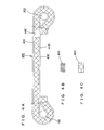
- FIG. 1 is a schematic side elevational view showing a main portion of a seat structure relating to an embodiment of the present invention, being in a state before an impact force equal to or stronger than that prescribed is applied;
- FIG. 2 is a schematic side elevational view showing a main portion of the seat structure relating to an embodiment of the present invention, being in a state after the impact force equal to or stronger than that prescribed is applied;
- FIG. 3A is a sectional view taken along an arrow A in FIG. 1, and FIG. 3B is a sectional view taken along an arrow B in FIG. 2;
- FIGs. 4A, 4B and 4C show desirable examples of a three-dimensional net member (solid knitted fabric) used for a cushioning member, in which FIG. 4A shows the solid knitted fabric being strained on a seat frame before an impact force equal to or stronger than that prescribed being applied, FIG. 4B is a view showing a structure of a ground knitted fabric on the back side, and FIG. 4C shows a structure of the ground knitted fabric on the front side;
- FIG. 5 is a view showing a solid knitted fabric in a state after an impact force equal to or stronger than that prescribed is applied;
- FIG. 6 is a view showing an example of a measurement result of the intensity of the backward moment;
- FIG. 7 is a view showing another example of a measurement result of the intensity of the backward moment;
- FIG. 8 is a view showing tensile properties of a two-dimentional net member used as a flat spring member;
- FIG. 9 is a view showing an appearance in a no-load state, when supported by a supporting frame which is biased backward together with the cushioning member and a flat spring member by a torsion bar; and
- FIG. 10 is a view showing the cushioning member in a state of being seated by a person.
-
- The present invention will be explained in more detail based on embodiments shown in the drawings. FIGs. 1 and 2 are views showing a main portion of a seat structure relating to an embodiment of the present invention. As shown in these drawings, a
seat cushion 10 and aseat back 20 forming the seat structure of the present embodiment include acushion frame 100 and aback frame 200 respectively. - The
cushion frame 100 is formed with a plurality of frame members such asside frames 101 disposed apart from and opposite to each other in the width direction, afront edge frame 102 disposed between both front ends of theside frames 101 and the like so as to form nearly a square or the shape of a letter U seen from the top as a whole. To theside frame 101, afixing bracket 103 is fixed along the bottom edge thereof and theside frame 101 is slidably supported by arail 111 which forms aslide adjuster 110 via thefixing bracket 103. - The
side frame 101 which is one of the frame members of thecushion frame 100 deforms by a backward rotation moment (backward moment) against the seat back 20 (back frame 200), when an impact force equal to or stronger than that prescribed is applied in the longitudinal direction due to a head-on or rear-end collision as shown in Fig. 2. Due to such deformation of theside frame 101, the intensity of the backward moment of theseat back 20 is varied. In order to relieve the impact caused by the deformation at this time, abead portion 101a which is bent to bulge outward is formed in theside frame 101, as shown in FIG. 1 and FIG. 3A, in the vicinity of the upper end edge of theside frame 101, at the position a little close to the back end from the central in the longitudinal direction. Through this structure, when an impact force equal to or stronger than that prescribed is applied to the seat back 20 as described above, theside frame 101 bends downward from the middle in the longitudinal direction with respect to therail 111 of theslide adjuster 110 by the backward moment. At this time, since thebead portion 101a stretches in the longitudinal direction as shown in FIGs. 2 and 3B, proceeding of rupture of theside frame 101 is restrained so that the impact is relaxed. - A
first bracket 104 is connected to the rear end of theside frame 101 of thecushion frame 100. Thefirst bracket 104 is connected to asecond bracket 201 via a recliningadjuster 30. Thesecond bracket 201 is fixed to the bottom end of aback frame 200. Accordingly, theback frame 200 is provided so as to be able to recline with respect to thecushion frame 100 via the recliningadjuster 30. It should be noted that in the present embodiment, thefirst bracket 104 constitutes a portion of thecushion frame 100, and thesecond bracket 201 constitutes a portion of theback frame 200. It is needless to say that in the case of a structure without the recliningadjuster 30, thefirst bracket 104 and thesecond bracket 201 are directly connected with bolts or the like. - A projecting plate (not shown) projecting inward is provided in the
first bracket 104 which constitutes thecushion frame 100 and is fixed at the rear end of theside frame 101, and a bracket for disposing thetorsion bar 105 is fixed to the projecting plate so that thebracket 105 projects downward. - The brackets for disposing the
torsion bar 105 are provided on eachside frame 101 disposed apart from each other at a prescribed distance in the width direction of thecushion frame 100, one end portion (fixed end) of atorsion bar 120 is fitted to a hole formed in one of the bracket for disposing thetorsion bar 105, and the other end portion (free end) of thetorsion bar 120 is rotatably supported in a hole of the other bracket for disposing thetorsion bar 105. Accordingly, thetorsion bar 120 is provided along the width direction of theseat cushion 10 or thecushion frame 100, and exhibits a prescribed spring characteristic by twisting of the free end side. - An
arm 121 is fixed in the vicinity of each end portion of thetorsion bar 120. One of thearms 121 disposed on the fixed end side of thetorsion bar 120 is pivotably disposed to thetorsion bar 120 at the base end portion thereof, and theother arm 121 disposed on the free end side of thetorsion bar 120 is directly connected to thetorsion bar 120 at the base end portion thereof, and is biased in a direction of backward tilt by twist torque thereof. A supportingframe 130 is disposed between the upper end portions ofrespective arms 121. Accordingly, the supportingframe 130 is elastically supported so as to be biased in a direction of backward tilt under a normal state by the spring characteristic of thetorsion bar 120 via thearm 121. - The supporting
frame 130 is used for a frame member to engage with oneend 41 of aflat spring member 40. Theother end 42 of theflat spring member 40 is engaged with thefront edge frame 102 which is one of the frame members to compose thecushion frame 100. Accordingly, while theflat spring member 40 is supported by thefront edge frame 102 at theother end 42, since oneend 41 is biased backward by an elastic force of thetorsion bar 120, theflat spring member 40 is strained in the longitudinal direction of theseat cushion 10 at a prescribed tension. - As a result that the
flat spring member 40 is strained at a prescribed tension as described above, vibration in a usual range inputted in the direction of the normal can be dispersed in the facial direction so that the vibration can be effectively absorbed. In the case of the present embodiment, theflat spring member 40 is elastically supported by thetorsion bar 120 via the supportingframe 130 and thearm 121. In other words, thetorsion bar 120 biases the supportingframe 130 in a direction of backward tilt via thearm 121 as described above to strain theflat spring member 40, and the initial tension is adjusted so that the supporting frame 130 (arm 121) takes an unstably balanced position in an equilibrium state at the time of being seated. As a result, it becomes possible to react sensitively to a very little vibration, and at the same time, a firm feeling of stroke can be created owing to restorative power of thetorsion bar 120. Especially, since thetorsion bar 120 can create a well-balanced state, operating effectively the restorative power to displacement from no-load state to an equilibrium state, it has a high vibration absorptive function. Incidentally, the functions of theflat spring member 40 and thetorsion bar 120 at the time when an impact force equal to or stronger than that prescribed is applied in the longitudinal direction by a head-on or rear-end collision will be described later. - Considering the object of the present invention, while the
flat spring member 40 needs to be fixed in such a manner that it supplements an impact-resistant function exhibited by deformation of the seat frame (thecushion frame 100 and the back frame 200) to enhance impact resistance of the seat structure when an impact force equal to or stronger than that prescribed is applied in the longitudinal direction, it also needs to exhibit a sufficient vibration absorptive function even for a vibration usually inputted as described above. Though theflat spring member 40 is not to be limited so far as it is provided with such a function, the following member is used in the present embodiment. - That is, the
flat spring member 40 used in the present embodiment includes elastic yarn, either of the warp or the weft is composed of elastic yarn such as polyester elastomer fiber, polyurethane fiber or the like, and the other is composed of common yarn such as nylon fiber, polyester fiber or the like, which is smaller in elasticity than the elastic yarn. And desirably, as shown in FIG. 8, theflat spring member 40 should display a softening spring characteristic as tensile characteristics when pulled along the arrangement direction of the elastic yarn, and display a linear spring characteristic as tensile characteristics when pulled along the arrangement direction of the common yarn. When theflat spring member 40 is kept stretching by being applied an impact force equal to or more than that prescribed in the longitudinal direction, and the common yarn is finally ruptured, damping ratio can be increased by the softening spring characteristics. It should be noted that, as shown in FIG. 8, as for linear spring characteristics when pulled along a roll direction of the fabric material, which is the direction of common yarn arrangement, it is possible to have a structure without non-linear characteristics at all as is seen fromroll direction 1, or a structure having non-linear characteristics in an initial bending region (a region in amount of bending to be usually 10 mm or less (roll direction 2) or 20 mm or less at maximum (roll direction 3)) by selecting materials or yarn diameter of the common yarn or the like. By taking a structure having non-linear characteristics in the initial bending region, a feeling of stroke at the time of being seated can be increased. Incidentally, the tensile characteristics shown in FIG. 8 are obtained by measuring in such a manner that using a test piece cut from the above-described two-dimensional net member in 200 mm long and 50 mm width, the test piece is pulled along the longitudinal direction at a rate of 50 mm/min by a test machine while taking a portion from each end in the longitudinal direction to 50 mm inside of the test piece as a margin for gripping. At this time, for the tensile characteristics along the arrangement direction of the elastic yarn, a test piece cut in such a manner that the arrangement direction of the elastic yarn being along the longitudinal direction is used, while for the tensile characteristics along the arrangement direction of the common yarn, a test piece cut in such a manner that the arrangement direction of the common yarn being along the longitudinal direction is used. - According to the seat structure of the present embodiment, at the time of normal use, absorption of vibration is achieved by the operation of the
flat spring member 40 and thetorsion bar 120 as described above. On the contrary, when an impact force equal to or stronger than that prescribed is applied in the longitudinal direction by a head-on or rear-end collision, since the human body is restrained by a seat belt or the like, a big load is generated in a direction of tilting the seat back 20 backward in any case. By a backward moment to tilt the seat back 20 in the backward turning direction, as shown in FIG. 2, theside frame 101 of thecushion frame 100 is deformed to bend downward at an arbitrary position from the vicinity of nearly central portion to the vicinity of the rear end, and around the position lower than the position where theflat spring member 40 is disposed in a normal state. At this time, thebead portion 101a provided in the vicinity of upper end edge of theside frame 101 stretches in the longitudinal direction as shown in FIG. 3B so that proceeding of rupture of theside frame 101 is restrained. - When the
side frame 101 is deformed, the fixingbracket 103 which supports theside frame 101 on therail 111 of theslide adjustor 110 similarly bends. In this event, since the amount of deformation of theside frame 101 is larger due to a difference in strength between theside frame 101 and the fixingbracket 103, the bottom end of thefirst bracket 104 integrally connected to the rear end of theside frame 101 abuts arear end portion 103a of the fixingbracket 103 to temporarily restrain the deformation of theside frame 101. Accordingly, therear end portion 103a of the fixingbracket 103 serves a function as a stopper to restrain the deformation of theside frame 101. - At this time, the intensity of the backward moment which is yield strength against a backward turning direction of the
back frame 200 gradually increases after receiving a prescribed impact force, as shown in FIG. 6, and at a point of A, theside frame 101 of thecushion frame 100 and theback frame 200 start deforming. Then, inclination in intensity of the backward moment slightly changes from the point A. When theflat spring member 40 is not provided, change in the intensity of the backward moment is greatly reduced at this time. However, according to the present embodiment, as thecushion frame 100 deforms, tension of theflat spring member 40 increases along with backward displacement of theback frame 200 to further increase the intensity of the backward moment. A point "B" is a point where deformation due to stretching of thebead portion 101a at the maximum or generation of cracks starts appearing as described above, and the intensity of the backward moment starts lowering from the point B. Since deformation of theside frame 101 is restrained when theside frame 101 abuts the rear end portion of the fixingbracket 103, tension of theflat spring member 40 greatly works from the time of abutting (point C) and the intensity of the backward moment starts to increase again. When deformation of theside frame 101 further proceeds, the intensity of the moment starts lowering again from a point D due to generation of a crack in thebeat portion 101a stretched at the maximum or enlargement of the crack previously generated, but since tension of theflat spring member 40 becomes large, the intensity of the backward moment turns to increase again from point E. - Due to the deformation of the
side frame 101 as described above, the intensity of the backward moment of theback frame 200 changes as described above. Previously, while the intensity of the backward moment of theback frame 200 is kept at a prescribed criterion by such a deformation behavior of the seat frame, during which the vicinity from the haunches to the waist of a human body pushes a thin cushioning member such as a solid knitted fabric or the like strained on theback frame 200 to allow it to operate as if buried into theback frame 200 so that the reaction of the human body is restrained. However, there is a limit, because this impact absorption mechanism utilizes only deformation behavior of the seat frame. - On the contrary, according to the present embodiment, when deformation of the
side frame 101 proceeds and bending downward is going on as described above, since the bracket for disposing thetorsion bar 105 which is fixed to theside frame 101, displaces also in a downward slanting direction, thearm 121 tilts backward along with displacement of theback frame 200 in a direction of backward tilt so that the supportingframe 130 is displaced backward. Since one end of theflat spring member 40 is supported by the supportingframe 130 and the other end of the flat supportingmember 40 is engaged with thefront edge frame 102, tension of theflat spring member 40 becomes high. Accordingly, as described above, even when inclination of the intensity of the backward moment is changed due to enlargement of the deformation of theside frame 101, since tension of theflat spring member 40 is increased as the amount of deformation of theside frame 101 and the amount of deformation of theback frame 200 in a direction of backward tilt are enlarged in the case of the present embodiment, the intensity of the backward moment can be enhanced by the tension of theflat spring member 40. As a result, tilting of the seat back 20 is restrained, and the back of a human body is supported by a cushion member such as a solid knitted fabric strained by theback frame 200 more reliably than by the prior art. In other words, in the present embodiment, theflat spring member 40 performs mainly vibration absorptive function in normal times, but when a large impact force as described above is inputted, it functions as a high-impact material to enhance the intensity of the backward moment of theback frame 200. - FIG. 7 shows the intensity of the backward moment measured while disposing the
flat spring member 40 similarly to the above, to a seat frame structure in which material of a little higher strength than the material used in the test in FIG. 6 is used as respective frame members to compose thecushion frame 100 and theback frame 200, without using a stopper for stopping deformation of thecushion frame 100 such as therear end portion 103a of the fixingbracket 103 described above. - As shown in FIG. 7, in the case of this example, deformation occurs to the
cushion frame 100 and theback frame 200 at point F, and thereafter the function of tension of theflat spring member 40 is added to create the intensity of backward moment of more than 3000 Nm. Then, a large deformation of thecushion frame 100 or theback frame 200, or stretch, crack, or the like in the bead portion occurs, which lowers the intensity of the backward moment at point G, but the tension of theflat spring member 40 becomes high again, and the intensity of the backward moment increases again from point H. When deformation of thecushion frame 100 and theback frame 200, cracks, or the like becomes large again, the intensity of the backward moment begins to lower again from point I, and it begins to increase again by tension increase of theflat spring member 40 when arriving at point J. - In the case of relying on the intensity of the
cushion frame 100 or theback frame 200, it is not easy to attain the intensity of the backward moment to be equal to or more than 3000 Nm. If such a structure is realized, it is expected to be considerably heavy. However, by adding theflat spring member 40 as a high-impact material as in the present embodiment, it is found it easy to attain the intensity of the backward moment to be equal to or more than 3000 Nm. As for thecushion frame 100 or theback frame 200, it is enough to select the one being a little high in strength, so that a structure having high intensity of the backward moment being light in weight can be realized. - Note that the measurement of the intensity of the backward moment shown in FIGs. 6 and 7 is carried out in either case by setting a designed hip point (H. P) of an apparatus in which a loading jig is provided to a back pan of a three-dimensional mannequin to a designated seating position on the seat structure, and applying a backward load (at a loading speed of 0.5 deg/s) to generate a moment of 588 Nm/person around H. P to the seat back.
- The cushioning members of urethane material or a solid knitted fabric are disposed above the
flat spring members 40 provided on thecushion frame 100 and theback frame 200 respectively. It is needless to say that these cushioning members are sometimes used as a surface material also with themselves or they may be further covered with another surface material such as a leather. - It is desirable to use a solid knitted
fabric 400 as shown in FIGs. 4 and 5 as a cushioning member. The solid knittedfabric 400 is formed by allowing connectingyarn 430 to reciprocate between two layers of front and back ground knittedfabrics fabric 400 is light in weight and air-permeable, and has a sufficient function as a cushioning member even with the thickness of about several millimeters to several tens millimeters due to a restoring force by a tilt of the connectingyarn 430, friction between connectingyarn 430, friction between connectingyarn 430 and yarn composing the ground knittedfabrics fabrics - The ground knitted
fabric 410 used for a back layer is, for instance as shown in FIG. 4B, formed with a flat knitted structure (small mesh) continuing in any directions of wale and course from yarn twined of monofilaments. On the other hand, theground fabric 420 used for a front layer is formed in a stitch structure having a honeycomb (hexagonal) mesh from yarn twined of monofilaments as shown in FIG. 4C. Needless to say, this knitted fabric structure is just an example, and a mesh structure or a knitted fabric structures except a honeycomb structure can be adopted. Theconnected yarn 430 is used for knitting between the pair of the ground knittedfabrics fabric 420 being the front layer and the ground knittedfabric 410 being the back layer can maintain a prescribed distance to give prescribed stiffness to the solid knittedfabric 400. - When the above-described solid
knitted fabric 400 is strained on thecushion frame 100 is provided, as shown in FIG. 4A, by engaging the front end with thefront edge frame 102, and the rear end is engaged with abottom frame 202 provided at the lower part of theback frame 200 for instance. Incidentally, though not shown, the side edge portion is engaged with theside frame 101. It is desirable that the solid knittedfabric 400 provided on thecushion frame 100 is not provided with connectingyarn 430 in a portion thereof, as shown in FIGs. 4A, 4B and 4C, and of a structure including a portion without connectingyarn 440 where the ground knittedfabrics - In the case of using such a solid knitted
fabric 400, when thecushion frame 100 and theback frame 200 reach a state shown in FIG 2 from a state shown in FIG. 1 under application of an impact force equal to or more than that prescribed in the longitudinal direction, since thebottom frame 202 displaces rearward, more correctly in a rearward slanting direction, the solid knittedfabric 400 stretches in the longitudinal direction as shown in FIG. 5 from a state shown in FIG. 4A. As a result, the tension of the solid knittedfabric 400 in the longitudinal direction is enhanced to serve as a function to supplementary further increase the intensity of the backward moment increased by the tension of the above-describedflat spring member 40. - However, in the case of a structure having no portion without connecting
yarn 440, the ground knittedfabrics yarn 430 tilts at the same time, the total thickness becomes thinner which heightens the surface stiffness in the thickness direction (direction of the normal) to lower the cushioning ability in the direction of the normal. On the contrary, in the case of a structure including the portion without connecting yarn as in the present embodiment, since positions directly facing each other in the portion without connectingyarn 440 is to be intensively stretched, between the ground knittedfabrics yarn 430 disposed in positions other than the portion without connectingyarn 440 do not tilt so much, and keep nearly the same state as that before the impact force is applied. As a result, lowering of the impact force in the direction of the normal accompanied by the stretch in the longitudinal direction is restrained, so that a relieving function of the impact force generated especially in the vertical direction can be enhanced when an impact force is applied. - The solid knitted
fabric 400 described above is disposed above theflat spring member 40, but it is also possible to use the solid knittedfabric 400 itself as aflat spring member 40, and to engage the rear end of the solid knittedfabric 400 with the supportingframe 130 supported by the torsion bar. Even in this case, by making it a structure to be provided with the portion without connectingyarn 430, the ground knittedfabrics yarn 440 are stretched, thereby restraining deformation of thecushion frame 100 and the back frames 200, exhibiting a function to enhance the intensity of the backward moment of the seat back 20, restraining excessive tilt of the connectingyarn 430, and making the cushioning ability in the vertical direction exhibit sufficiently. - As shown in FIG. 9, it is also possible to adopt a structure in which one
end 41 of theflat spring member 40 and the rear end of the solid knittedfabric 400 are engaged together with the supportingframe 130 supported by the torsion bar. In this case, since the supportingframe 130 is biased in the direction backward tilt by an elastic force of the torsion bar at the time of no load, the solid knittedfabric 400 strained on the front sides shows an appearance without needless shrinks and folds. On the other hand, when a person is seated, since the supportingframe 130 is tilted forward as shown in FIG. 10, the solid knittedfabric 400 does not increase in tension but creates slack. Therefore, the cushioning ability in the thickness direction included in the solid knittedfabric 400 can be exhibited sufficiently. It should be noted that it is desirable to use the solid knittedfabric 400 as described above, it is also possible to use comparatively thin urethane material. - A seat structure of the present invention has a structure in which a flat spring member mainly serving as a vibration absorptive function at a normal use is engaged with an arbitrary frame member which displaces backward along with deformation of a seat back by backward moment applied to the seat back, and the other end is engaged with a frame member disposed in the vicinity of the front edge of a cushion frame. Therefore, when an impact force from front or back equal to or more than that prescribed is applied, the flat spring member increases in tension by backward moment applied to the seat back, and serves as a function to increase the intensity of the backward moment of the seat back. Therefore, according to the present invention, high intensity of the backward moment can be exhibited compared with that in the prior art so that further improvement of the impact resistance can be realized.
Claims (10)
- A seat structure, comprising:wherein the flat spring member increases in tension as said seat back is deformed.a flat spring member disposed in such a manner that one end is in engagement with an arbitrary frame member to be displaced backward by backward moment, which deforms a seat back under an impact force from front or back equal to or stronger than that prescribed, and the other end is in engagement with a frame member disposed in the vicinity of the front edge of a cushion frame,
- A seat structure, comprising:wherein the flat spring member increases in tension accompanied by deformation of said seat back to perform a function to increase the intensity of the backward moment of the seat back.a cushion frame provided with a frame member deforming under an impact force from front or back equal to or stronger than that prescribed; anda flat spring member disposed in such a manner that one end thereof is in engagement with an arbitrary frame member to be displaced backward along with deformation of a seat back by backward moment applied to said seat back, and the other end is in engagement with the frame member disposed in the vicinity of the front edge of the cushion frame,
- The seat structure according to claims 1 or 2, wherein the arbitrary frame member engaged with one end of said flat spring member and displacing backward by the backward moment toward said seat back includes a frame member composing a back frame.
- The seat structure according to claims 1 or 2, wherein the arbitrary frame member engaged with one end of said flat spring member and displacing backward by the backward moment toward said seat back comprises the frame member elastically supported in an independent state from the back frame, and provided at a position corresponding to the vicinity from the haunches to the waist, along the width direction of the seat.
- The seat structure according to claim 4, wherein the arbitrary frame displacing backward by backward moment toward said seat back comprises a frame member composing said cushion frame, and is supported by an arm biased in a direction of backward tilt under a normal state by means of a torsion bar disposed along the width direction at a position to be deformed by an impact force equal to or stronger than that prescribed to said seat back.
- The seat structure according to claims 1 or 2, further comprising:a stopper to control deformation of the cushion frame and the back frame under an impact force from front or back equal to or stronger than that prescribed.
- The seat structure according to claim 1 or 2, wherein said flat spring member comprises one kind selected from a two-dimensional net member and a three-dimensional net member or a combination of two kinds or more thereof.
- The seat structure according to claims 1 or 2,
wherein said cushion member comprises one kind selected from a two-dimensional net member, a three-dimensional net member and a urethane material or a combination of two kinds or more thereof, and is disposed above the flat spring member in such a manner that one end thereof is in engagement with the arbitrary frame member to be displaced backward along with deformation of the seat back by backward moment applied to the seat back and the other end is in engagement with a frame member disposed in the vicinity of the front edge of the cushion frame. - The seat structure according to claim 8, wherein said cushioning member comprises a three-dimensional net member formed by connecting two layers of front and back of ground knitted fabrics with connecting yarn.
- The seat structure according to claim 9, further comprising:a portion without connecting yarn at the arbitrary position between one end and the other end of said three-dimensional net member where no connecting yarn is provided and the ground knitted fabrics directly face each other.
Applications Claiming Priority (3)
| Application Number | Priority Date | Filing Date | Title |
|---|---|---|---|
| JP2002208957 | 2002-07-17 | ||
| JP2002208957 | 2002-07-17 | ||
| PCT/JP2003/009089 WO2004007238A1 (en) | 2002-07-17 | 2003-07-17 | Seat construction |
Publications (3)
| Publication Number | Publication Date |
|---|---|
| EP1552981A1 true EP1552981A1 (en) | 2005-07-13 |
| EP1552981A4 EP1552981A4 (en) | 2010-09-29 |
| EP1552981B1 EP1552981B1 (en) | 2012-09-12 |
Family
ID=30112864
Family Applications (1)
| Application Number | Title | Priority Date | Filing Date |
|---|---|---|---|
| EP03764216A Expired - Fee Related EP1552981B1 (en) | 2002-07-17 | 2003-07-17 | Seat construction |
Country Status (7)
| Country | Link |
|---|---|
| US (1) | US7303229B2 (en) |
| EP (1) | EP1552981B1 (en) |
| JP (1) | JP4554362B2 (en) |
| KR (1) | KR100601765B1 (en) |
| CN (1) | CN100421989C (en) |
| TW (1) | TWI231750B (en) |
| WO (1) | WO2004007238A1 (en) |
Cited By (2)
| Publication number | Priority date | Publication date | Assignee | Title |
|---|---|---|---|---|
| EP1743800A3 (en) * | 2005-07-14 | 2010-09-08 | Delta Tooling Co., Ltd. | Seat |
| EP1733919A3 (en) * | 2005-06-13 | 2010-10-06 | Delta Tooling Co., Ltd. | Base net supporting mechanism for seat and seat structure thereof |
Families Citing this family (24)
| Publication number | Priority date | Publication date | Assignee | Title |
|---|---|---|---|---|
| JP2006175976A (en) * | 2004-12-22 | 2006-07-06 | Tachi S Co Ltd | Impact absorbing seat structure for vehicle |
| JP4860932B2 (en) * | 2005-02-04 | 2012-01-25 | テイ・エス テック株式会社 | Shock-absorbing automotive seat |
| JP4554444B2 (en) | 2005-06-13 | 2010-09-29 | 株式会社デルタツーリング | Seat structure |
| DE102006038771A1 (en) * | 2006-08-17 | 2008-02-21 | Recaro Aircraft Seating Gmbh & Co. Kg | seat device |
| JP5179798B2 (en) | 2007-05-22 | 2013-04-10 | 株式会社デルタツーリング | Seat structure |
| US7527334B2 (en) * | 2007-06-18 | 2009-05-05 | Ford Global Technologies, Llc | Automotive seat reclining system |
| JP5255831B2 (en) | 2007-12-27 | 2013-08-07 | 株式会社デルタツーリング | Shock absorbing structure, shell-type frame member and seat structure |
| US8500196B2 (en) * | 2008-04-15 | 2013-08-06 | Britax Child Safety, Inc. | Child seat having a crush zone |
| JP5408688B2 (en) * | 2008-05-28 | 2014-02-05 | 株式会社デルタツーリング | Sheet |
| US8371655B2 (en) * | 2008-10-20 | 2013-02-12 | Nhk Spring Co., Ltd. | Seat cushion frame structure of seat for vehicle and seat for vehicle with seat cushion frame structure |
| DE102009056731A1 (en) | 2009-12-04 | 2011-06-09 | Rev Renewable Energy Ventures, Inc. | Halogenated polysilanes and polygermanes |
| US8172320B2 (en) * | 2010-02-11 | 2012-05-08 | Nissan North America, Inc. | Impact absorption block for vehicle seatback assembly |
| CN101905664B (en) * | 2010-03-23 | 2012-01-11 | 浙江吉利汽车研究院有限公司 | Anti-rear collision neck protection seat |
| US9434281B2 (en) * | 2010-09-14 | 2016-09-06 | Basf Se | Energy absorbing seat for a vehicle |
| DE102010051325B4 (en) * | 2010-11-16 | 2020-11-26 | Grammer Aktiengesellschaft | Seat base for a person seat |
| JP5788216B2 (en) * | 2011-05-13 | 2015-09-30 | 日本発條株式会社 | Cushion seat frame structure for vehicle seat and vehicle seat having the structure |
| KR101394742B1 (en) * | 2012-09-19 | 2014-05-15 | 현대자동차주식회사 | Seat control device and method be considered human engineering |
| JP6166643B2 (en) * | 2013-01-23 | 2017-07-19 | 株式会社デルタツーリング | Vehicle seat |
| JP6111471B2 (en) * | 2013-08-09 | 2017-04-12 | トヨタ紡織株式会社 | Vehicle seat |
| SE541442C2 (en) * | 2015-09-07 | 2019-10-01 | Ningbo Geely Automobile Res & Development Co Ltd | Method and vehicle seat arrangement comprising a deformation portion |
| DE102016209053B4 (en) | 2016-05-25 | 2020-01-02 | Lear Corporation | Vehicle seat with end stop with clearance to improve rigidity and method of assembling a vehicle seat |
| CN109789820A (en) * | 2016-09-27 | 2019-05-21 | 普罗马有限公司 | The seat of vehicle with joint edge |
| CN106813916B (en) * | 2017-03-03 | 2023-05-23 | 山东省农业机械科学研究院 | Tractor seat and safety belt strength test system |
| GB2561548B (en) * | 2017-03-31 | 2019-07-17 | Acro Aircraft Seating Ltd | Energy absorbing device |
Citations (2)
| Publication number | Priority date | Publication date | Assignee | Title |
|---|---|---|---|---|
| WO1997010117A1 (en) * | 1995-09-14 | 1997-03-20 | Autoliv Development Ab | A seat for use in a vehicle |
| JP2002012072A (en) * | 2000-06-30 | 2002-01-15 | Takata Corp | Seat for moving body |
Family Cites Families (9)
| Publication number | Priority date | Publication date | Assignee | Title |
|---|---|---|---|---|
| FR2562002B1 (en) * | 1984-03-27 | 1986-08-22 | Peugeot Cycles | DEVICE FOR LOCALLY ADJUSTING THE TENSION OF AN ELASTIC SHEET AND ELASTIC SHEET, PARTICULARLY FOR A SEAT BACKREST, PROVIDED WITH SUCH A DEVICE |
| US5295729A (en) * | 1992-02-18 | 1994-03-22 | General Motors Corporation | High retention seat back |
| DE4436139C1 (en) * | 1994-10-10 | 1996-03-21 | Autoliv Dev | Motor vehicle passenger seat with side impact protection |
| NL9401985A (en) * | 1994-11-25 | 1996-07-01 | Johannes Theodorus Marie Rasen | Seat and vehicle equipped with it. |
| US5810417A (en) * | 1995-09-28 | 1998-09-22 | Mongkol Jesadanont | Automatic safety car seats and sheet-type safety-belt |
| US6485098B1 (en) * | 1998-10-30 | 2002-11-26 | Indiana Mills & Manufacturing, Inc. | Restraint system for a school bus seat |
| JP4666724B2 (en) * | 2000-07-10 | 2011-04-06 | 株式会社デルタツーリング | Folding seat |
| US6378939B1 (en) * | 2000-09-25 | 2002-04-30 | East/West Industries, Inc. | Variable energy attenuating apparatus |
| JP2003180481A (en) | 2001-12-20 | 2003-07-02 | Delta Tooling Co Ltd | Seat |
-
2003
- 2003-07-16 TW TW092119442A patent/TWI231750B/en not_active IP Right Cessation
- 2003-07-17 CN CNB03816826XA patent/CN100421989C/en not_active Expired - Fee Related
- 2003-07-17 EP EP03764216A patent/EP1552981B1/en not_active Expired - Fee Related
- 2003-07-17 JP JP2004521227A patent/JP4554362B2/en not_active Expired - Fee Related
- 2003-07-17 WO PCT/JP2003/009089 patent/WO2004007238A1/en active IP Right Grant
- 2003-07-17 US US10/520,458 patent/US7303229B2/en not_active Expired - Fee Related
- 2003-07-17 KR KR1020057000533A patent/KR100601765B1/en not_active IP Right Cessation
Patent Citations (2)
| Publication number | Priority date | Publication date | Assignee | Title |
|---|---|---|---|---|
| WO1997010117A1 (en) * | 1995-09-14 | 1997-03-20 | Autoliv Development Ab | A seat for use in a vehicle |
| JP2002012072A (en) * | 2000-06-30 | 2002-01-15 | Takata Corp | Seat for moving body |
Non-Patent Citations (1)
| Title |
|---|
| See also references of WO2004007238A1 * |
Cited By (3)
| Publication number | Priority date | Publication date | Assignee | Title |
|---|---|---|---|---|
| EP1733919A3 (en) * | 2005-06-13 | 2010-10-06 | Delta Tooling Co., Ltd. | Base net supporting mechanism for seat and seat structure thereof |
| EP1743800A3 (en) * | 2005-07-14 | 2010-09-08 | Delta Tooling Co., Ltd. | Seat |
| US7845733B2 (en) | 2005-07-14 | 2010-12-07 | Delta Tooling Co., Ltd. | Seat |
Also Published As
| Publication number | Publication date |
|---|---|
| US7303229B2 (en) | 2007-12-04 |
| CN1668489A (en) | 2005-09-14 |
| US20050231011A1 (en) | 2005-10-20 |
| JPWO2004007238A1 (en) | 2005-11-10 |
| TW200402277A (en) | 2004-02-16 |
| TWI231750B (en) | 2005-05-01 |
| CN100421989C (en) | 2008-10-01 |
| JP4554362B2 (en) | 2010-09-29 |
| EP1552981B1 (en) | 2012-09-12 |
| KR100601765B1 (en) | 2006-07-19 |
| EP1552981A4 (en) | 2010-09-29 |
| WO2004007238A1 (en) | 2004-01-22 |
| KR20050013178A (en) | 2005-02-02 |
Similar Documents
| Publication | Publication Date | Title |
|---|---|---|
| EP1552981B1 (en) | Seat construction | |
| EP1415853B1 (en) | Seat structure with anti-submarining device | |
| KR100499757B1 (en) | Seat structure | |
| US7503627B2 (en) | Seat | |
| US6921132B2 (en) | Seat structure | |
| US7731294B2 (en) | Seat | |
| KR100468285B1 (en) | Vehicle seat | |
| JP4250128B2 (en) | Sheet | |
| JP4836422B2 (en) | Sheet | |
| JP2003182427A (en) | Shock absorbing structure and seat structure | |
| JP2003180481A (en) | Seat | |
| JP4169599B2 (en) | Seat structure | |
| JP6557462B2 (en) | Lumber support structure and seat structure | |
| JP2004188164A (en) | Seat structure | |
| JP5210043B2 (en) | Seat structure | |
| JP2004237820A (en) | Seat for vehicle |
Legal Events
| Date | Code | Title | Description |
|---|---|---|---|
| PUAI | Public reference made under article 153(3) epc to a published international application that has entered the european phase |
Free format text: ORIGINAL CODE: 0009012 |
|
| 17P | Request for examination filed |
Effective date: 20050118 |
|
| AK | Designated contracting states |
Kind code of ref document: A1 Designated state(s): DE FR GB |
|
| A4 | Supplementary search report drawn up and despatched |
Effective date: 20100827 |
|
| 17Q | First examination report despatched |
Effective date: 20101207 |
|
| GRAP | Despatch of communication of intention to grant a patent |
Free format text: ORIGINAL CODE: EPIDOSNIGR1 |
|
| GRAS | Grant fee paid |
Free format text: ORIGINAL CODE: EPIDOSNIGR3 |
|
| GRAA | (expected) grant |
Free format text: ORIGINAL CODE: 0009210 |
|
| AK | Designated contracting states |
Kind code of ref document: B1 Designated state(s): DE FR GB |
|
| REG | Reference to a national code |
Ref country code: GB Ref legal event code: FG4D |
|
| REG | Reference to a national code |
Ref country code: DE Ref legal event code: R096 Ref document number: 60342105 Country of ref document: DE Effective date: 20121108 |
|
| PLBE | No opposition filed within time limit |
Free format text: ORIGINAL CODE: 0009261 |
|
| STAA | Information on the status of an ep patent application or granted ep patent |
Free format text: STATUS: NO OPPOSITION FILED WITHIN TIME LIMIT |
|
| 26N | No opposition filed |
Effective date: 20130613 |
|
| REG | Reference to a national code |
Ref country code: DE Ref legal event code: R097 Ref document number: 60342105 Country of ref document: DE Effective date: 20130613 |
|
| REG | Reference to a national code |
Ref country code: FR Ref legal event code: PLFP Year of fee payment: 13 |
|
| REG | Reference to a national code |
Ref country code: FR Ref legal event code: PLFP Year of fee payment: 14 |
|
| REG | Reference to a national code |
Ref country code: FR Ref legal event code: PLFP Year of fee payment: 15 |
|
| PGFP | Annual fee paid to national office [announced via postgrant information from national office to epo] |
Ref country code: DE Payment date: 20170720 Year of fee payment: 15 Ref country code: FR Payment date: 20170726 Year of fee payment: 15 Ref country code: GB Payment date: 20170720 Year of fee payment: 15 |
|
| REG | Reference to a national code |
Ref country code: DE Ref legal event code: R119 Ref document number: 60342105 Country of ref document: DE |
|
| GBPC | Gb: european patent ceased through non-payment of renewal fee |
Effective date: 20180717 |
|
| PG25 | Lapsed in a contracting state [announced via postgrant information from national office to epo] |
Ref country code: GB Free format text: LAPSE BECAUSE OF NON-PAYMENT OF DUE FEES Effective date: 20180717 Ref country code: FR Free format text: LAPSE BECAUSE OF NON-PAYMENT OF DUE FEES Effective date: 20180731 Ref country code: DE Free format text: LAPSE BECAUSE OF NON-PAYMENT OF DUE FEES Effective date: 20190201 |