EP1552897A2 - Werkzeugaufnahmevorrichtung - Google Patents
Werkzeugaufnahmevorrichtung Download PDFInfo
- Publication number
- EP1552897A2 EP1552897A2 EP04029435A EP04029435A EP1552897A2 EP 1552897 A2 EP1552897 A2 EP 1552897A2 EP 04029435 A EP04029435 A EP 04029435A EP 04029435 A EP04029435 A EP 04029435A EP 1552897 A2 EP1552897 A2 EP 1552897A2
- Authority
- EP
- European Patent Office
- Prior art keywords
- clamping
- tool
- pin
- receiving body
- recess
- Prior art date
- Legal status (The legal status is an assumption and is not a legal conclusion. Google has not performed a legal analysis and makes no representation as to the accuracy of the status listed.)
- Withdrawn
Links
- 238000003780 insertion Methods 0.000 claims abstract description 12
- 230000037431 insertion Effects 0.000 claims abstract description 12
- 238000010521 absorption reaction Methods 0.000 description 3
- 238000013461 design Methods 0.000 description 2
- 238000012545 processing Methods 0.000 description 2
- 230000003068 static effect Effects 0.000 description 2
- 230000000295 complement effect Effects 0.000 description 1
- 230000003750 conditioning effect Effects 0.000 description 1
- 238000010276 construction Methods 0.000 description 1
- 230000000694 effects Effects 0.000 description 1
- 238000010348 incorporation Methods 0.000 description 1
- 230000000977 initiatory effect Effects 0.000 description 1
- 230000003993 interaction Effects 0.000 description 1
- 238000003754 machining Methods 0.000 description 1
- 230000006641 stabilisation Effects 0.000 description 1
- 238000011105 stabilization Methods 0.000 description 1
- 238000012549 training Methods 0.000 description 1
Images


Classifications
-
- B—PERFORMING OPERATIONS; TRANSPORTING
- B23—MACHINE TOOLS; METAL-WORKING NOT OTHERWISE PROVIDED FOR
- B23B—TURNING; BORING
- B23B31/00—Chucks; Expansion mandrels; Adaptations thereof for remote control
- B23B31/02—Chucks
- B23B31/10—Chucks characterised by the retaining or gripping devices or their immediate operating means
- B23B31/107—Retention by laterally-acting detents, e.g. pins, screws, wedges; Retention by loose elements, e.g. balls
- B23B31/1075—Retention by screws
- B23B31/1077—Retention by screws acting on a floating pin
-
- B—PERFORMING OPERATIONS; TRANSPORTING
- B23—MACHINE TOOLS; METAL-WORKING NOT OTHERWISE PROVIDED FOR
- B23B—TURNING; BORING
- B23B29/00—Holders for non-rotary cutting tools; Boring bars or boring heads; Accessories for tool holders
- B23B29/04—Tool holders for a single cutting tool
- B23B29/046—Tool holders for a single cutting tool with an intermediary toolholder
Definitions
- the invention relates to a tool receiving device with a receiving body, can be used in the at least one tool and by means of a bracing device can be fixed, which has adjustable clamping means.
- Such a tool receiving device is specified in DE 203 11 391 U1.
- a bracing device stably releasably braced with each other, wherein a shank of the tool in introduced a receptacle or bore of the receiving body and therein by means Chuck is set.
- the bracing device has a transversely through the Recording and the shaft extending passage with a conical bore, which cooperates with an outer cone of a performed clamping bolt such that the shank of the tool is drawn into the receiving body, up to the insertion direction arranged support surfaces of the receiving body and of the tool come into abutment against each other.
- the invention is based on the object, a tool receiving device of to provide the aforementioned type, with the versatility as versatile as possible a simple operation is achieved.
- the receiving body as a basic holder with two receptacles for optional insertion of the tool in two different, for example in axial or radial direction is formed, in which the at least one Tool with the same Verspannstoffn is fixed.
- the tool such as e.g. a cutter carrier tool, used in various positions in the receiving body and therein easy to set.
- the tool may be a non-rotating, act static tool or a rotating tool.
- the fixing with the same tensioning means in the two different positions of the Tool is done, also the construction is easy.
- An advantageous for the operation and bracing embodiment consists in that the tool is provided for fixing with a pin which in one of two adapted holes of the base holder can be used and with an end portion in an associated recess of a transverse to the two Holes inserted clamping bolt inserted and therein by means of clamping elements is clamped.
- the Verspannvortician and the release are thereby favored that the Tension slopes on conical shaped cones of the fixed and the adjustable Clamping element and the counter-clamping bevels on conical depressions of the pin are arranged.
- the clamping bolt only one recess for the end portion having the pin and that the recess by turning the clamping bolt alternately assignable to one of the two holes around its longitudinal axis is.
- the clamping bolt needs to Assignment to the respective receiving bores of the receiving body simply only to be rotated by 90 ° about its longitudinal axis.
- a stable, simple tension is further promoted by the fact that the Receiving body and the tool on their outer sides facing each other when bracing against each other be brought into abutment, transverse to the direction of insertion have oriented support surfaces.
- the mutual support surfaces are formed as flat planes or to each other have adapted recesses and projections. Are on both sides wells and adapted projections present, there is a clear alignability of the tool relative to the receiving body.
- the depressions and Projections can also contribute to the stabilization of the tool by providing contribute to the torque absorption in addition to the bracing device.
- a clear alignment of the tool and thus also of the processing element is also achieved in that in one of the support surfaces a positioning bolt and in the other support surface at least one adapted to this Positioning bolt receptacle is arranged. Again, the positioning carries for torque absorption at.
- the receiving body is provided with an exchange shaft or one in a tool turret has recorded holder.
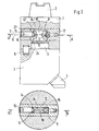
- FIG. 1 shows a first embodiment of the tool receiving device, in which the tool 3 by means of a pin 11 in a bore adapted thereto 24 of the receiving body 1 used, but not yet braced, in a in the region of the jig partially cut side view and in a cross section along a sectional plane A-A also in the region of the bracing device.
- Fig. 2 shows the corresponding tool receiving device as in Fig.
- the tool receiving device of FIG. 3 is a tool receiving body 1 with two offset by 90 ° staggered mounting holes in two various lateral views shown, with the shown, to be used Tools 25, 26 are set with the same bracing.
- the tool receiving device consists of the receiving body 1 with the shaft 2 for connection to the machine tool.
- a transverse bore 27 Transverse to the mounting hole 24 of the receiving body 1 in the radial direction is continuous introduced a transverse bore 27, in which a trained as a pendulum clamping bolt Clamping bolt 12 is oscillating or floating.
- the pendulum tension bolt 12 has a radially continuous or blind-hole-like groove-like Recess 21 into which an end portion 10 of the pin 11 is inserted.
- the Recess 21 is, as can be seen from the cross-sectional view, in plan view oblong with parallel longitudinal sides and circular rounded narrow sides formed, and the flap-like shaped end portion 10 is in his Cross section adapted to the recess 21.
- a fixed Clamping element 8 introduced with a conical end, a clamping bevel 8.1 to retract the pin 11 has.
- the fixed clamping element 8 is diametrically opposite an adjustable clamping element in the form of a movable Cone 14 associated with a further clamping slope 14.1, as in the Pendelspannbolzen 12 screwed or Tomosbarer from this threaded pin 13 is formed with a hexagon socket for insertion of a handle. Conceivable it would be, the fixed clamping element 8 and the adjustable clamping element 13 offset in the axial direction of the pin 11 against each other.
- Due to the tension with the pendulum clamping bolt 21 in The type shown results in a centering of the tool 3, wherein transverse forces be avoided on the pin 11 in the bore 24 and a safe collection of the tool 3 and a fixed tension can be achieved. Also can be easily release the tool 3 from the receiving body 1 again.
- a positioning bolt 5 used and in the other support surface at least one corresponding Recess provided. Thereby, e.g. the position of the cutting edge 4 tuned become.
- the positioning pin 5 can in addition to the clamping device for Incorporation of the torque occurring during machining.
- the clamping operation is carried out by screwing in the adjustable Clamping element 14 in the form of threaded pin 13.
- the relevant clamping bevel 14.1 and the associated counter-clamping bevel 9.1 of the end portion 10 moves on further screwing the threaded pin 13 of the pendulum clamping bolt 12 in or against the screwing. It comes to contact between the fixed clamping element 8 and the relevant conical recess 9.
- By initiating a corresponding Torque on the threaded pin 13 is due to deflection of the clamping force the interface or the support surfaces between the receiving body 1 and the tool 3 generates an axial clamping force. Because no power losses through Radial forces arise, the full induced force comes under deduction relative low frictional forces at the interface to the effect.
- FIG. 3 is different from the Exemplary embodiment according to FIGS. 1 and 2 by way of example by a static tool 25, 26, for example, also a cutter support tool.
- a shaft On the receiving body 1 in the form of the base holder 20 is a shaft, e.g. in shape a standardized clamping pin 19 added.
- a bore 24 As a receptacle for the pin 11 with its end portion 15 (e.g., corresponding to the end portion 10).
- Another Bore 24 is 90 ° to the axis of the first bore or the clamping pin 19 offset, wherein the two holes 24 in the common Cross hole 27 open, in accordance with the embodiment of the Fig. 1 and 2 of the clamping bolt 12 and 12A is used oscillating.
- each other applicable tools 25, 26, in which it can be the same tool are optional turning operations axially and radially feasible in two axial directions.
- the pendulum tension bolt 12a configured such that it by means of a pin wrench, the in frontal holes 18 can be used, can be rotated by 90 °.
- the two bores 24 are assigned Support surfaces of the receiving body 1 with projections and recesses provided, which are formed for example as four radius segments.
- Appropriate complementary recesses and projections are assigned to the Support surface of the tool 25, 26 formed so that a unique, torsionally stable assembly of the tool 25, 26 and the receiving body 1 is guaranteed when tightening.
Landscapes
- Engineering & Computer Science (AREA)
- Mechanical Engineering (AREA)
- Jigs For Machine Tools (AREA)
- Gripping On Spindles (AREA)
- Workshop Equipment, Work Benches, Supports, Or Storage Means (AREA)
Abstract
Description
- Fig. 1
- eine Werkzeugaufnahmevorrichtung mit einem Aufnahmekörper und einem darin eingesetzten Werkzeug in teilweise geschnittener Seitenansicht und im Querschnitt entlang einer Schnittebene A-A, in einem nicht festgespannten Zustand,
- Fig. 2
- die Werkzeugaufnahmevorrichtung nach Fig. 1 in einem festgespannten Zustand und
- Fig. 3
- eine weitere Werkzeugaufnahmevorrichtung mit einem Aufnahmekörper und darin in zwei verschiedenen Stellungen einsetzbaren und mit einer Verspannvorrichtung festlegbaren Werkzeugen.
Claims (10)
- Werkzeugaufnahmevorrichtung mit einem Aufnahmekörper (1; 20), in dem mindestens ein Werkzeug (3; 25, 26) einsetzbar und mittels einer Verspannvorrichtung festlegbar ist, die verstellbare Verspannmittel (12, 1 2a, 8, 13) aufweist,
dadurch gekennzeichnet, dass der Aufnahmekörper als Grundhalter (20) mit zwei Aufnahmen (24) zum wahlweisen Einsetzen des Werkzeuges (3; 25, 26) in zwei verschiedenen Richtungen ausgebildet ist, in denen das mindestens eine Werkzeug (3; 25, 26) mit denselben Verspannmitteln (12, 12a, 8, 13) festlegbar ist. - Vorrichtung nach Anspruch 1,
dadurch gekennzeichnet, dass das Werkzeug (3; 25, 26) zum Festlegen mit einem Zapfen (11) versehen ist, der in eine von zwei daran angepasste Bohrungen (24) des Grundhalters (20) einsetzbar ist und mit einem Endabschnitt (10) in eine zugeordnete Ausnehmung (21) eines quer zu den beiden Bohrungen (24) eingesetzten Spannbolzens (12, 12a) einführbar und darin mittels Spannelemente (8, 13) festspannbar ist. - Vorrichtung nach Anspruch 2,
dadurch gekennzeichnet, dass der Spannbolzen (12, 12a) pendelnd gelagert ist und ein in der Ausnehmung (12) angebrachtes Spannelement (8) mit einer in Einführrichtung des Zapfens (11) mit diesem zusammenwirkenden Spannschräge (8.1) aufweist und mit einem dem Spannelement (8) in der Ausnehmung (12) gegenüberliegenden verstellbaren Spannelement (13) versehen ist, welches eine in Einführrichtung des Zapfens (11) ebenfalls mit diesem zusammenwirkende weitere Spannschräge (13.1) aufweist. - Vorrichtung nach Anspruch 2 oder 3,
dadurch gekennzeichnet, dass in dem Zapfen (11) zum Zusammenwirken mit den Spannschrägen (8.1, 13.1) angepasste Gegenspannschrägen (9.1) ausgebildet sind. - Vorrichtung nach Anspruch 4,
dadurch gekennzeichnet, dass die Spannschrägen (8.1, 13.1) an konisch geformten Kegeln (14) des feststehenden (8) und des verstellbaren Spannelementes (13) und die Gegenspannschrägen (9.1) an konischen Vertiefungen (9) des Zapfens angeordnet sind. - Vorrichtung nach einem der Ansprüche 2 bis 5,
dadurch gekennzeichnet, dass der Spannbolzen (12, 12a) nur eine Ausnehmung (21) für den Endabschnitt (10) des Zapfens (11) aufweist und
dass die Ausnehmung durch Drehen des Spannbolzens (12, 12a) um seine Längsachse wechselweise einer der beiden Bohrungen (24) zuordenbar ist. - Vorrichtung nach einem der vorhergehenden Ansprüche,
dadurch gekennzeichnet, dass der Aufnahmekörper (1; 20) und das Werkzeug (3; 25, 26) auf ihren einander zugekehrten Außenseiten beim Verspannen gegeneinander in Widerlage bringbare, quer zur Einführrichtung orientierte Stützflächen (22, 23) aufweisen. - Vorrichtung nach Anspruch 7,
dadurch gekennzeichnet, dass die beiderseitigen Stützflächen (22, 23) als flache Ebenen ausgebildet sind oder aneinander angepasste Vertiefungen und Vorsprünge aufweisen. - Vorrichtung nach Anspruch 7 oder 8,
dadurch gekennzeichnet, dass in einer der Stützflächen (22 oder 23) ein Positionierbolzen (5) und in der anderen Stützfläche (23 oder 22) mindestens eine an diesen angepasste Positionierbolzenaufnahme angeordnet ist. - Vorrichtung nach einem der vorhergehenden Ansprüche,
dadurch gekennzeichnet, dass der Aufnahmekörper (1; 20) mit einem Wechselschaft (19) versehen ist oder einen in einem Werkzeugrevolver aufgenommenen Halter aufweist.
Applications Claiming Priority (2)
| Application Number | Priority Date | Filing Date | Title |
|---|---|---|---|
| DE102004001148 | 2004-01-07 | ||
| DE200410001148 DE102004001148B3 (de) | 2004-01-07 | 2004-01-07 | Werkzeugaufnahmevorrichtung |
Publications (2)
| Publication Number | Publication Date |
|---|---|
| EP1552897A2 true EP1552897A2 (de) | 2005-07-13 |
| EP1552897A3 EP1552897A3 (de) | 2008-08-27 |
Family
ID=34530453
Family Applications (1)
| Application Number | Title | Priority Date | Filing Date |
|---|---|---|---|
| EP04029435A Withdrawn EP1552897A3 (de) | 2004-01-07 | 2004-12-13 | Werkzeugaufnahmevorrichtung |
Country Status (2)
| Country | Link |
|---|---|
| EP (1) | EP1552897A3 (de) |
| DE (1) | DE102004001148B3 (de) |
Families Citing this family (2)
| Publication number | Priority date | Publication date | Assignee | Title |
|---|---|---|---|---|
| DE102006027947A1 (de) * | 2006-06-17 | 2007-12-20 | Wiedmann, Jörg | Spannkopf |
| DE102017118501A1 (de) * | 2017-08-14 | 2019-02-14 | Mas Gmbh | Werkzeughalteranordnung und Verfahren zum Herstellen eines Werkzeughalters |
Citations (4)
| Publication number | Priority date | Publication date | Assignee | Title |
|---|---|---|---|---|
| DE3433878A1 (de) | 1984-09-14 | 1986-03-27 | August Beck GmbH & Co, 7472 Winterlingen | Axial-spannverbindung |
| WO2000053361A1 (en) | 1999-03-11 | 2000-09-14 | Sunspot Edm Tooling | Tool holder |
| DE20311391U1 (de) | 2003-07-24 | 2003-09-18 | Schweizer, Herbert, 74357 Bönnigheim | Vorrichtung zum lösbaren Verspannen zweier Bauteile |
| EP1007255B1 (de) | 1997-08-29 | 2003-10-22 | Sandvik Aktiebolag | Werkzeugkupplung |
Family Cites Families (3)
| Publication number | Priority date | Publication date | Assignee | Title |
|---|---|---|---|---|
| DE8614678U1 (de) * | 1986-05-30 | 1986-08-07 | Metallwerke Gebr. Seppelfricke Gmbh & Co, 4650 Gelsenkirchen | Werkzeughalter für auswechselbare Zerspanungswerkzeuge von Werkzeugmaschinen |
| DE8904239U1 (de) * | 1989-04-06 | 1989-06-29 | Zinner GmbH Präzisionswerkzeuge, 8500 Nürnberg | Werkzeug-Grundhalter zur Befestigung in einer Aufnahme-Aussparung eines Werkzeugträgers, insbesondere Revolverkopfes |
| DE29914491U1 (de) * | 1999-08-18 | 2000-01-05 | Index-Werke Gmbh & Co Kg Hahn & Tessky, 73730 Esslingen | Werkzeugrevolver für Drehmaschine |
-
2004
- 2004-01-07 DE DE200410001148 patent/DE102004001148B3/de not_active Expired - Fee Related
- 2004-12-13 EP EP04029435A patent/EP1552897A3/de not_active Withdrawn
Patent Citations (4)
| Publication number | Priority date | Publication date | Assignee | Title |
|---|---|---|---|---|
| DE3433878A1 (de) | 1984-09-14 | 1986-03-27 | August Beck GmbH & Co, 7472 Winterlingen | Axial-spannverbindung |
| EP1007255B1 (de) | 1997-08-29 | 2003-10-22 | Sandvik Aktiebolag | Werkzeugkupplung |
| WO2000053361A1 (en) | 1999-03-11 | 2000-09-14 | Sunspot Edm Tooling | Tool holder |
| DE20311391U1 (de) | 2003-07-24 | 2003-09-18 | Schweizer, Herbert, 74357 Bönnigheim | Vorrichtung zum lösbaren Verspannen zweier Bauteile |
Also Published As
| Publication number | Publication date |
|---|---|
| DE102004001148B3 (de) | 2005-06-02 |
| EP1552897A3 (de) | 2008-08-27 |
Similar Documents
| Publication | Publication Date | Title |
|---|---|---|
| EP0687516B1 (de) | Kombinationswerkzeug | |
| EP1868756B1 (de) | Werkzeugaufbau | |
| DE102007039367B4 (de) | Werkzeugbefestigung | |
| DE10326928B4 (de) | Schnittstelle zwischen zwei Teilelementen eines Werkzeugsystems | |
| DE4032176C2 (de) | Scheibenschneider | |
| DE69117286T2 (de) | Bohrer mit Senkgerät | |
| DE112013000583B4 (de) | Sägeblattspannvorrichtung | |
| EP3519130B1 (de) | Stechschwert | |
| EP1447195B1 (de) | Bohrvorrichtung mit einem Hohlbohrer | |
| EP3703893B1 (de) | Fräswerkzeug-halter und fräswerkzeug | |
| CH648226A5 (de) | In einem halter eines maschinenwerkzeuges, insbesondere drehwerkzeuges, einsetzbarer schneidplattentraeger. | |
| EP2906378B1 (de) | Aufsatzvorrichtung für ein bohrsystem sowie bohrsystem zum ausbohren eines verbindungselementes | |
| EP3016770B1 (de) | Wechselkopfsystem für die metallbearbeitung | |
| DE102019111843B4 (de) | Zerspanungswerkzeug | |
| EP0033086B1 (de) | Bohrwerkzeug mit einem Wendebohrmesser | |
| WO2008052623A1 (de) | Werkzeughalter | |
| DE102004001148B3 (de) | Werkzeugaufnahmevorrichtung | |
| DE4311109A1 (de) | Modulares Werkzeugsystem | |
| DE102005051545B4 (de) | Werkzeughalter | |
| DE102016205658B3 (de) | Schneidwerkzeug mit einem an einem trägerkörper durch eine spannpratze lösbar befestigtem schneidkörper | |
| DE3511580A1 (de) | Werkzeug-spannvorrichtung | |
| EP2254715B1 (de) | Werkzeug | |
| DE3432942C2 (de) | ||
| DE102020100064B3 (de) | Vorrichtung zur Aufnahme eines Zerspanungswerkzeugs | |
| EP0389788A2 (de) | Kombination zur Herstellung kreisrunder Ausnehmungen mit stufenlos veränderbarem Durchmesser im vollen Material |
Legal Events
| Date | Code | Title | Description |
|---|---|---|---|
| PUAI | Public reference made under article 153(3) epc to a published international application that has entered the european phase |
Free format text: ORIGINAL CODE: 0009012 |
|
| AK | Designated contracting states |
Kind code of ref document: A2 Designated state(s): AT BE BG CH CY CZ DE DK EE ES FI FR GB GR HU IE IS IT LI LT LU MC NL PL PT RO SE SI SK TR |
|
| AX | Request for extension of the european patent |
Extension state: AL BA HR LV MK YU |
|
| PUAL | Search report despatched |
Free format text: ORIGINAL CODE: 0009013 |
|
| AK | Designated contracting states |
Kind code of ref document: A3 Designated state(s): AT BE BG CH CY CZ DE DK EE ES FI FR GB GR HU IE IS IT LI LT LU MC NL PL PT RO SE SI SK TR |
|
| AX | Request for extension of the european patent |
Extension state: AL BA HR LV MK YU |
|
| 17P | Request for examination filed |
Effective date: 20090227 |
|
| AKX | Designation fees paid |
Designated state(s): AT BE BG CH CY CZ DE DK EE ES FI FR GB GR HU IE IS IT LI LT LU MC NL PL PT RO SE SI SK TR |
|
| 17Q | First examination report despatched |
Effective date: 20091013 |
|
| STAA | Information on the status of an ep patent application or granted ep patent |
Free format text: STATUS: THE APPLICATION IS DEEMED TO BE WITHDRAWN |
|
| 18D | Application deemed to be withdrawn |
Effective date: 20110701 |