EP1552465B1 - Apparat mit ic-karten-leser und überlastungsschutz - Google Patents
Apparat mit ic-karten-leser und überlastungsschutz Download PDFInfo
- Publication number
- EP1552465B1 EP1552465B1 EP03792290A EP03792290A EP1552465B1 EP 1552465 B1 EP1552465 B1 EP 1552465B1 EP 03792290 A EP03792290 A EP 03792290A EP 03792290 A EP03792290 A EP 03792290A EP 1552465 B1 EP1552465 B1 EP 1552465B1
- Authority
- EP
- European Patent Office
- Prior art keywords
- card
- supply voltage
- vcc
- overload
- circuit
- Prior art date
- Legal status (The legal status is an assumption and is not a legal conclusion. Google has not performed a legal analysis and makes no representation as to the accuracy of the status listed.)
- Expired - Lifetime
Links
Images

Classifications
-
- G—PHYSICS
- G06—COMPUTING OR CALCULATING; COUNTING
- G06K—GRAPHICAL DATA READING; PRESENTATION OF DATA; RECORD CARRIERS; HANDLING RECORD CARRIERS
- G06K17/00—Methods or arrangements for effecting co-operative working between equipments covered by two or more of main groups G06K1/00 - G06K15/00, e.g. automatic card files incorporating conveying and reading operations
-
- G—PHYSICS
- G06—COMPUTING OR CALCULATING; COUNTING
- G06K—GRAPHICAL DATA READING; PRESENTATION OF DATA; RECORD CARRIERS; HANDLING RECORD CARRIERS
- G06K7/00—Methods or arrangements for sensing record carriers, e.g. for reading patterns
- G06K7/0013—Methods or arrangements for sensing record carriers, e.g. for reading patterns by galvanic contacts, e.g. card connectors for ISO-7816 compliant smart cards or memory cards, e.g. SD card readers
- G06K7/0086—Methods or arrangements for sensing record carriers, e.g. for reading patterns by galvanic contacts, e.g. card connectors for ISO-7816 compliant smart cards or memory cards, e.g. SD card readers the connector comprising a circuit for steering the operations of the card connector
-
- G—PHYSICS
- G06—COMPUTING OR CALCULATING; COUNTING
- G06F—ELECTRIC DIGITAL DATA PROCESSING
- G06F1/00—Details not covered by groups G06F3/00 - G06F13/00 and G06F21/00
- G06F1/26—Power supply means, e.g. regulation thereof
-
- G—PHYSICS
- G06—COMPUTING OR CALCULATING; COUNTING
- G06K—GRAPHICAL DATA READING; PRESENTATION OF DATA; RECORD CARRIERS; HANDLING RECORD CARRIERS
- G06K7/00—Methods or arrangements for sensing record carriers, e.g. for reading patterns
- G06K7/0013—Methods or arrangements for sensing record carriers, e.g. for reading patterns by galvanic contacts, e.g. card connectors for ISO-7816 compliant smart cards or memory cards, e.g. SD card readers
Definitions
- the present invention relates to an appliance having an IC card reader for operation with an IC card.
- Appliances of this kind are known for example from pay television broadcast (pay TV), electronic payment, or banking services.
- IC cards also known as smart cards, are portable information media, having the size of about a credit card. They comprise an integrated card controller, or at least an integrated memory, for a data exchange with a respective appliance. A portable device of this kind is known for example from EP-A-0 633 544 . As a general term for this data media the expression "IC card” will be used throughout in this description. IC cards are usually provided with contacts being mechanically contacted by an IC card reader for an electrical connection for the data exchange with the respective appliance.
- IC cards The communication between IC cards and respective appliances with IC card readers is described for example in WO 97/25685 and EP-A-0 814 427 .
- the respective IC cards comprise data, which enable the set-top box to unscramble received coded video signals.
- the appliance comprises an IC card reader for an operation with an IC card and a power supply for providing a supply voltage, in particular for the IC card reader.
- the appliance comprises further an overload protection circuit, which simulates an IC card extraction in case of an overload of the supply voltage. The power supply is then immediately switched off to avoid any damage for the power supply.
- the IC card reader is equipped with a card presence switch for indicating to a micro-controller of the appliance, that an IC card has been inserted into the card reader.
- the micro-controller provides then a control signal for switching on the power supply for the operation with the IC card. Power to the IC card is therefore only provided, when a signal of the card presence switch indicates that an IC card has been inserted.
- the overload protection circuit changes the positive signal of the card presence switch to a value, which states that no IC card is present. Therefore, an extraction of the IC card is simulated.
- the overload protection circuit is coupled between the supply voltage for the IC card and the signal line of the card presence switch and provides a detection of a short circuit.
- the protection circuit may comprise a diode, a comparator or a transistor, which resets the value of the card presence switch to a value, which simulates that no IC card is present.
- a logic circuit is used, to control the switching on and off of the power supply for the IC card.
- the card presence signal and the power on/off signal from the micro-controller are coupled and the operation of the logic circuit is such, that the power supply is only switched on, when an IC card is inserted applying a positive signal from the card presence switch to the logic circuit, and when the micro-controller provides the command signal for switching on the supply voltage.
- the logic circuit switches through for turning the power to the IC card on.
- the logic circuit is for example an AND circuit or a NAND circuit. When a short circuit occurs, the power to the IC card is immediately switched off via the logic circuit, independently from the micro-controller. The power is therefore switched off much faster, as could be performed by the micro-controller, which reduces the danger of damaging the power supply.
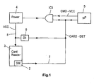
- the appliance shown in Fig. 1 comprises an IC card reader 3, which is powered by a power supply 4 via line 8.
- the IC card reader 3 comprises in particular a housing, in which a respective IC card can be inserted, and contact terminals for applying a supply voltage VCC to the IC card and for providing an exchange of digital data between the IC card and a micro-controller 5 of the appliance.
- the card reader 3 comprises further a card presence switch 2, which provides a signal "CARD-DET" viva a signal line 7 to the micro-controller 5, when an IC card is inserted.
- the card presence switch 2 is a mechanical switch, which is operated, when an IC card is inserted. If an IC card is inserted, the switch 2 is opened. Via a respective circuitry, as explained with regard to Fig. 2 , a logical "HIGH" signal, "CARD-DET", is provided then to the micro-controlled 5.
- an overload protection circuit 6 is coupled between the line 8 of the supply voltage VCC and the line 7 of the card detect signal, which converts in case of an overload of the supply voltage VCC the signal indicating the presence of an inserted IC card to a value, which states that no IC card is present.
- the overload of the supply voltage VCC simulates therefore via the protection circuit 6 an IC card extraction for switching off the power supply 4.
- the power supply 4 in this embodiment is switched on and off by a logic circuit IC3, to which inputs the signal from the card presence switch 2 "CARD-DET” is applied and the power on/off signal "CMD-VCC” from the micro- controller 5.
- the power supply 4 is then switched on only, when a positive signal from the card presence switch 2 is provided and a power on command from the micro-controller 5.
- the protection circuit 6 converts the signal from the card presence switch 2 from "CARD DETECTED” to "NO CARD PRESENT", and therefore switches off the power supply 4 immediately via the logic circuit IC3.
- the logic circuit IC3 is for example a NAND or an AND circuit.
- the protection circuit 6 may comprise an over-current protection circuit, which measures the current of line 8 for example via a measuring resistor, and which provides a respective signal for an overload, when the current provided by the power supply 4 is too high.
- the protection circuit 6 comprises a voltage detector for the supply voltage VCC, which uses a voltage threshold for determining a breakdown of the supply voltage VCC. This can be performed for example by a protection circuit comprising a comparator, a transistor or a diode, or by any other switching element. A supply voltage breakdown occurs for example in case of a short circuit.
- a detail of a digital set-top box comprising an IC card reader 3 and relevant parts for the operation of the set-top box with an IC card.
- the IC card reader 3 comprises an IC card connector 1 with contacts C1 - C8, for operation with an IC card according to the IEC 7816-3:1997(E) standard.
- the contacts C1 - C8 provide the following connections to an IC card: C1 for supply voltage VCC, C2 for a reset of the IC card, C3 for providing a clock signal CLK to the IC card, C4, C5 and C8 for providing ground terminal connections to the IC card, C6 (reserved for a programming voltage VPP) and C7 for providing a data input/output connection for a data exchange between the IC card and the set-top box.
- the set-top box comprises further an integrated circuit IC1, a buffer and line driver for the digital signals used for operation with the IC card.
- the respective signals which are coupled to the integrated circuit 1, are the reset signal “RESET-CARD” for contact C2, the clock signal “CLK-CARD” for contact C3, and data input and output signals "DOUT” and "DIN” for contact C7.
- the integrated circuit IC1 is for example an integrated circuit 74HCT244 from Texas Instrument. For the IC1, also for the IC card and the electronics of the IC card reader 4, a supply voltage of 5 Volts is used.
- the IC card reader 3 comprises a card presence switch 2 with switch contacts SW for a detection of an IC card, when an 1C card is inserted into the IC card connector 1.
- a supply voltage of 5 V is coupled via a resistor R1.
- the switch contacts SW are open.
- a transistor T1 is coupled via its base terminal to the switch contact PRES. The transistor T1 provides therefore a "LOW" output signal, when the switch 2 is open, (IC card inserted) and a "HIGH” output signal, when the switch 2 is closed.
- a NAND circuit IC2 is coupled, which is arranged as an inverter, for providing a signal "CARD-DET" for a micro-controller, not shown in Fig. 2 , of the set-top box.
- the micro-controller is for example a "system-on-chip” controlled STI5516 from ST Microelectronics.
- the output signal of the NAND circuit IC2 is therefore "HIGH", when an IC card is inserted.
- the output of IC2 is also coupled to an input of a NAND circuit IC3, for providing a supply voltage VCC to the IC card, terminal C1.
- a control signal "CMD-VCC" from the micro-controller is coupled.
- the micro-controller provides the signal "CMD-VCC” for switching on the supply voltage VCC for the IC card.
- the supply voltage VCC is provided by a transistor T2, to which base terminal the output of IC3 is coupled.
- transistor T2 switches through for supplying a 5 V supply voltage VCC to the contact C1 of the IC card connector 1.
- a diode D1 is coupled, which is arranged such, that the diode D1 conducts, when the signal from the switch contact is "HIGH", but the supply voltage VCC is low. Therefore, when the supply voltage VCC breaks down when an IC card is inserted, for example when the IC card has a short circuit between respective IC card contacts, the diode D1 switches through and therefore switches off transistor T1. Then the output of NAND circuit IC2 switches to "LOW", which switches off immediately the transistor T2 via NAND circuit IC3.
- the transistor T2 the power supply for the IC card, is switched off therefore immediately by transistor T1 and NAND circuits IC2 and IC3, and will not be damaged by a short circuit. There is a much smaller delay, as would be the case when the transistor T2 would be switched off via the micro-controller.
- the diode D1 provides therefore a very effective short circuit protection.
- buffer/line driver circuits with a controllable output can be used, for example integrated circuits Quad buffer/line driver 74HC125 or 74HC126, manufactured for example from Philips Semiconductors. These circuits comprise four non-inverting buffers, which outputs are controllable via a respective output enable input, the 74HC125 having active LOW enable inputs and the 74HC126 active HIGH enable inputs.
- the overload protection circuit 6, Fig. 1 may be arranged also within a power supply circuit, which provides then an error signal in case of an overload.
- a power supply circuit which provides then an error signal in case of an overload.
- an adjustable power voltage regulator LP2951 from Fairchild Semiconductor Corporation can be used, which provides an error signal in case of a low output voltage, which may occur for example in case of a short.
- the IC LP2951 is switched on and off via the signal CMD-VCC from micro-controller 5, see Fig. 1 .
- the error signal from IC LP2951 can be applied for example to the output enable input of a buffer/line driver circuit, IC 74HC125, to which input the card detected signal CARD-DET, Fig. 1 , is coupled, and which output is coupled to IC3 and to the micro-controller 5.
- the error signal from IC LP2951 then changes the output from the buffer/line driver circuit from positive to negative, simulating therefore an IC card extraction, which switches off the power supply 4 via IC3.
- the overload protection as described is especially suited for a digital set-top box or a satellite receiver operating with an IC card, but applications for other appliances having an IC card reader for operation with an IC card are also possible.
- the appliance may have also further IC card readers, which are protected in the same way.
Landscapes
- Engineering & Computer Science (AREA)
- Theoretical Computer Science (AREA)
- Physics & Mathematics (AREA)
- General Physics & Mathematics (AREA)
- Artificial Intelligence (AREA)
- Computer Vision & Pattern Recognition (AREA)
- General Engineering & Computer Science (AREA)
- Power Sources (AREA)
Claims (9)
- Vorrichtung, umfassend ein Chipkartenlesegerät (3) und eine Stromversorgung (4, T2), um eine in das Kartenlesegerät (3) einzuführende Chipkarte mit einer Versorgungsspannung (VCC) zu versorgen, wobei die Vorrichtung eine Überlastschutzschaltung (6, D1) umfasst, welche die Versorgungsspannung (VCC) bei Überlastung in der Stromversorgung (4, T2) abschaltet, dadurch gekennzeichnet, dass die Schutzschaltung (6, D1) Mittel zur Vortäuschung einer Chipkartenentnahme und Mittel zum sofortigen Abschalten der Versorgungsspannung (VCC) im Falle einer Überlastung der Versorgungsspannung (ICC) umfasst.
- Vorrichtung nach Anspruch 1, dadurch gekennzeichnet, dass das Chipkartenlesegerät (3) einen Kartenanwesenheitsschalter (2) umfasst und dass bei einer überlastung der Versorgungsspannung (VCC) die Überlastschutzschaltung (6, D1) ein Kartenerkennungssignal (CARD-DET) von positiv auf negativ umschaltet, um eine Chipkartenentnahme vorzutäuschen.
- Vorrichtung nach Anspruch 2, dadurch gekennzeichnet, dass die Überlastschutzschaltung (6, D1) zur Erkennung einer Überlastung der Versorgungsspannung (VCC) an den Kartenanwesenheitsschalter (2) und an die Versorgungsspannung (VCC) gekoppelt ist.
- Vorrichtung nach Anspruch 3, dadurch gekennzeichnet, dass die Überlastschutzschaltung (6, D1) eine Diode (D1), einen Komparator oder einen Schalter umfasst, die bzw. der zur Erkennung eines Spannungsausfalls der Versorgungsspannung (VCC) angeordnet ist.
- Vorrichtung nach einem der vorhergehenden Ansprüche, dadurch gekennzeichnet, dass an Eingänge eines Schaltmittels (IC3) ein Kartenerkennungssignal (CARD-DET) und ein von einem Mikrocontroller (5) gelieferter Befehl zur "EIN-/AUS"-Schaltung der Versorgungsspannung (CMD-VCC) gekoppelt ist, um die Stromversorgung (4, T2) nur dann einzuschalten, wenn das Kartenerkennungssignal (CARD-DET) positiv ist.
- Vorrichtung nach Anspruch 5, dadurch gekennzeichnet, dass das Schaltmittel (IC3) ein Logikschaltungsgatter ist, beispielsweise eine NICHT-UND- oder UND-Schaltung, oder eine Puffer-/Kabeltreiberschaltung mit einem Ausgangsfreigabe-Eingang.
- Vorrichtung nach Anspruch 1, 5 oder 6, dadurch gekennzeichnet, dass die Überlastschutzschaltung (6) innerhalb der Stromversorgungsschaltung (4) angeordnet ist, welche bei einer Überlastung ein Fehlersignal liefert, und dass bei einer überlastung der entsprechenden Versorgungsspannung (VCC) das Fehlersignal über eine Logikschaltung ein Kartenerkennungssignal (CARD-DET) von positiv auf negativ umschaltet, um eine Chipkartenentnahme vorzutäuschen.
- Vorrichtung nach einem der vorhergehenden Ansprüche, dadurch gekennzeichnet, dass die Versorgungsspannung (VCC) eine Versorgungsspannung für das Chipkartenlesegerät (3), insbesondere für einen Chipkartenkontakt (C1), ist.
- Vorrichtung nach einem der vorhergehenden Ansprüche, dadurch gekennzeichnet, dass die Vorrichtung eine digitale Set-Top-Box oder ein digitaler Satellitenempfänger mit einem entsprechenden Chipkartenlesegerät ist.
Priority Applications (1)
| Application Number | Priority Date | Filing Date | Title |
|---|---|---|---|
| EP03792290A EP1552465B1 (de) | 2002-08-21 | 2003-08-08 | Apparat mit ic-karten-leser und überlastungsschutz |
Applications Claiming Priority (4)
| Application Number | Priority Date | Filing Date | Title |
|---|---|---|---|
| EP02292063A EP1391840A1 (de) | 2002-08-21 | 2002-08-21 | Anordnung mit Chipkarten-Lesegerät und Überlastschutz |
| EP02292063 | 2002-08-21 | ||
| EP03792290A EP1552465B1 (de) | 2002-08-21 | 2003-08-08 | Apparat mit ic-karten-leser und überlastungsschutz |
| PCT/EP2003/008877 WO2004019259A1 (en) | 2002-08-21 | 2003-08-08 | Appliance with an ic card reader and overload protection |
Publications (2)
| Publication Number | Publication Date |
|---|---|
| EP1552465A1 EP1552465A1 (de) | 2005-07-13 |
| EP1552465B1 true EP1552465B1 (de) | 2009-10-21 |
Family
ID=30775893
Family Applications (2)
| Application Number | Title | Priority Date | Filing Date |
|---|---|---|---|
| EP02292063A Withdrawn EP1391840A1 (de) | 2002-08-21 | 2002-08-21 | Anordnung mit Chipkarten-Lesegerät und Überlastschutz |
| EP03792290A Expired - Lifetime EP1552465B1 (de) | 2002-08-21 | 2003-08-08 | Apparat mit ic-karten-leser und überlastungsschutz |
Family Applications Before (1)
| Application Number | Title | Priority Date | Filing Date |
|---|---|---|---|
| EP02292063A Withdrawn EP1391840A1 (de) | 2002-08-21 | 2002-08-21 | Anordnung mit Chipkarten-Lesegerät und Überlastschutz |
Country Status (10)
| Country | Link |
|---|---|
| US (1) | US7216809B2 (de) |
| EP (2) | EP1391840A1 (de) |
| JP (1) | JP4567451B2 (de) |
| KR (1) | KR100998211B1 (de) |
| CN (1) | CN100337242C (de) |
| AU (1) | AU2003253401A1 (de) |
| DE (1) | DE60329775D1 (de) |
| MX (1) | MXPA05001577A (de) |
| WO (1) | WO2004019259A1 (de) |
| ZA (1) | ZA200500733B (de) |
Families Citing this family (16)
| Publication number | Priority date | Publication date | Assignee | Title |
|---|---|---|---|---|
| CN101169816B (zh) * | 2006-10-26 | 2011-05-25 | 北京华旗资讯数码科技有限公司 | 电子卡的保护电路 |
| US20110267190A1 (en) * | 2010-05-03 | 2011-11-03 | Irvine Sensors Corporation | Anti-Tampering Detection Using Target Circuit RF Signature |
| US8649820B2 (en) * | 2011-11-07 | 2014-02-11 | Blackberry Limited | Universal integrated circuit card apparatus and related methods |
| US8936199B2 (en) | 2012-04-13 | 2015-01-20 | Blackberry Limited | UICC apparatus and related methods |
| US10380471B2 (en) * | 2013-07-23 | 2019-08-13 | Capital One Services, Llc | Dynamic transaction card power management |
| US9619792B1 (en) | 2014-03-25 | 2017-04-11 | Square, Inc. | Associating an account with a card based on a photo |
| CN105100303A (zh) * | 2014-05-22 | 2015-11-25 | 中兴通讯股份有限公司 | 电源保护装置及终端设备 |
| US9679234B2 (en) * | 2014-07-01 | 2017-06-13 | Square, Inc. | Charging card using power harvested from reader |
| US10304053B1 (en) | 2014-08-08 | 2019-05-28 | Square, Inc. | Shopping check-out with a payment card |
| US10296910B1 (en) | 2014-08-08 | 2019-05-21 | Square, Inc. | Pay-by-name payment check-in with a payment card |
| US10614450B1 (en) | 2014-08-08 | 2020-04-07 | Squre, Inc. | Controlled emulation of payment cards |
| CN104464783A (zh) * | 2014-12-18 | 2015-03-25 | 江苏天安智联科技股份有限公司 | 一种车载存储卡接口短路保护装置 |
| CN107949853A (zh) | 2015-04-14 | 2018-04-20 | 第资本服务公司 | 防篡改动态交易卡和提供防篡改动态交易卡的方法 |
| CN108256364B (zh) * | 2017-12-29 | 2020-12-29 | 浙江大华汽车技术有限公司 | 一种ic卡热插拔检测电路 |
| CN112067976B (zh) * | 2020-09-18 | 2024-12-17 | 无锡翼盟电子科技有限公司 | 一种用于打印设备耗材芯片防止高压击穿电路 |
| CN112288068B (zh) * | 2020-10-24 | 2024-02-27 | 卓捷创芯科技(深圳)有限公司 | 一种无源射频识别标签的正反馈闩锁限幅控制电路和方法 |
Family Cites Families (18)
| Publication number | Priority date | Publication date | Assignee | Title |
|---|---|---|---|---|
| JPS62105293A (ja) * | 1985-10-31 | 1987-05-15 | Toshiba Corp | 携帯可能記録媒体の読取・書込装置 |
| JPS62114085A (ja) * | 1985-11-13 | 1987-05-25 | Nippon Telegr & Teleph Corp <Ntt> | Icカ−ドの保護回路 |
| JPH0255355U (de) * | 1988-10-11 | 1990-04-20 | ||
| US5790946A (en) * | 1993-07-15 | 1998-08-04 | Rotzoll; Robert R. | Wake up device for a communications system |
| RU2150745C1 (ru) * | 1995-03-22 | 2000-06-10 | Фраматом Коннектор Энтернасьональ | Система считывания карточек с микросхемой |
| JP2000516358A (ja) * | 1995-12-22 | 2000-12-05 | トムソン コンシユーマ エレクトロニクス インコーポレイテツド | Ir受信器と電子機器との間の電気的絶縁装置 |
| JP3486057B2 (ja) * | 1996-06-21 | 2004-01-13 | 株式会社東芝 | 半導体集積回路及び接触式icカード |
| JPH10243544A (ja) * | 1997-02-27 | 1998-09-11 | Toshiba Corp | 過電流保護回路と過電流保護回路の過電流保護方法 |
| EP0874327A3 (de) * | 1997-04-21 | 2003-02-12 | Samsung Electronics Co., Ltd. | Chipkarte, die von einer externen Vorrichtung gelieferte Spannungen einstellen kann |
| US5963144A (en) * | 1997-05-30 | 1999-10-05 | Single Chip Systems Corp. | Cloaking circuit for use in a radiofrequency identification and method of cloaking RFID tags to increase interrogation reliability |
| JPH11154137A (ja) * | 1997-11-20 | 1999-06-08 | Hitachi Ltd | 個人作業環境設定方式 |
| US6484946B2 (en) * | 1997-12-22 | 2002-11-26 | Hitachi, Ltd. | IC card information display device and IC card for use therewith |
| EP0953936B1 (de) * | 1998-02-17 | 2001-05-09 | Infineon Technologies AG | Datenträger sowohl für den kontaktlosen als auch den kontaktbehafteten Betrieb |
| US6318632B1 (en) * | 1998-07-30 | 2001-11-20 | Airborn, Inc. | Smart card reader with electrostatic discharge protection |
| FR2795881B1 (fr) * | 1999-06-30 | 2001-08-31 | St Microelectronics Sa | Circuit de production d'une haute tension de programmation d'une memoire |
| JP2002222391A (ja) * | 2001-01-29 | 2002-08-09 | Matsushita Electric Ind Co Ltd | メモリカード管理装置及びメモリカード管理方法 |
| JP2002231344A (ja) * | 2001-02-02 | 2002-08-16 | Jst Mfg Co Ltd | フラッシュメモリカード用コネクタ |
| US7293710B2 (en) * | 2004-04-03 | 2007-11-13 | Alcor Micro, Corp. | Method of overcurrent protection for multi-slot flash memory card reader |
-
2002
- 2002-08-21 EP EP02292063A patent/EP1391840A1/de not_active Withdrawn
-
2003
- 2003-08-08 WO PCT/EP2003/008877 patent/WO2004019259A1/en not_active Ceased
- 2003-08-08 EP EP03792290A patent/EP1552465B1/de not_active Expired - Lifetime
- 2003-08-08 DE DE60329775T patent/DE60329775D1/de not_active Expired - Lifetime
- 2003-08-08 US US10/525,056 patent/US7216809B2/en not_active Expired - Lifetime
- 2003-08-08 JP JP2004530119A patent/JP4567451B2/ja not_active Expired - Fee Related
- 2003-08-08 CN CNB038197375A patent/CN100337242C/zh not_active Expired - Fee Related
- 2003-08-08 MX MXPA05001577A patent/MXPA05001577A/es active IP Right Grant
- 2003-08-08 AU AU2003253401A patent/AU2003253401A1/en not_active Abandoned
- 2003-08-08 KR KR1020057002763A patent/KR100998211B1/ko not_active Expired - Fee Related
-
2006
- 2006-01-25 ZA ZA200500733A patent/ZA200500733B/xx unknown
Also Published As
| Publication number | Publication date |
|---|---|
| CN1675647A (zh) | 2005-09-28 |
| MXPA05001577A (es) | 2005-04-25 |
| US7216809B2 (en) | 2007-05-15 |
| CN100337242C (zh) | 2007-09-12 |
| JP4567451B2 (ja) | 2010-10-20 |
| JP2006505028A (ja) | 2006-02-09 |
| KR20050058354A (ko) | 2005-06-16 |
| WO2004019259A1 (en) | 2004-03-04 |
| ZA200500733B (en) | 2006-03-29 |
| EP1552465A1 (de) | 2005-07-13 |
| AU2003253401A1 (en) | 2004-03-11 |
| US20050247785A1 (en) | 2005-11-10 |
| EP1391840A1 (de) | 2004-02-25 |
| DE60329775D1 (de) | 2009-12-03 |
| KR100998211B1 (ko) | 2010-12-07 |
Similar Documents
| Publication | Publication Date | Title |
|---|---|---|
| EP1552465B1 (de) | Apparat mit ic-karten-leser und überlastungsschutz | |
| EP0595305B1 (de) | IC Kartenleser | |
| KR100321516B1 (ko) | 칩카드 | |
| EP1540359B1 (de) | VERFAHREN UND TESTADAPTER ZUM TESTEN EINES GERäTS MIT EINEM CHIPKARTENLESER | |
| EP0341712B1 (de) | IC-Karte mit Sicherungsmitteln gegen fehlerhaften Betrieb | |
| US20100205341A1 (en) | Card recognition method for micro sd adapter | |
| EP0874327A2 (de) | Chipkarte, die von einer externen Vorrichtung gelieferte Spannungen einstellen kann | |
| KR100390964B1 (ko) | 데이터 처리 장치와 데이터 처리 장치의 동작 제어 방법 | |
| EP1348194B1 (de) | System und verfahren zur spannungsschaltung | |
| KR100387343B1 (ko) | 디지탈 회로를 이용하여 단자 모드와 rf 모드 사이를스위칭하는 데이타 처리 장치 | |
| US20070257116A1 (en) | Interface detection method of a multiple mode micro memory card | |
| US6796501B2 (en) | Smart card reader circuit and method of monitoring | |
| WO2001006443A1 (en) | Method and apparatus for supporting two different types of integrated circuit cards with a single connector | |
| US9087230B2 (en) | Method for communicating by a detector of the presence of chip cards in a reader chip cards and a reading device communicating by the presence detector | |
| CN100468447C (zh) | 卡存取装置以及实现该卡存取装置的电子装置 | |
| HK1032653A (en) | Data processing device and method of controlling operation of data processing device | |
| CN101099159A (zh) | 通过读取器中的芯片卡存在检测器进行通信的方法、芯片卡和通过存在检测器进行通信的读取设备 | |
| KR100652764B1 (ko) | 이동단말기의 플래시/이어잭 검출 회로 |
Legal Events
| Date | Code | Title | Description |
|---|---|---|---|
| PUAI | Public reference made under article 153(3) epc to a published international application that has entered the european phase |
Free format text: ORIGINAL CODE: 0009012 |
|
| 17P | Request for examination filed |
Effective date: 20050208 |
|
| AK | Designated contracting states |
Kind code of ref document: A1 Designated state(s): AT BE BG CH CY CZ DE DK EE ES FI FR GB GR HU IE IT LI LU MC NL PT RO SE SI SK TR |
|
| AX | Request for extension of the european patent |
Extension state: AL LT LV MK |
|
| RAP1 | Party data changed (applicant data changed or rights of an application transferred) |
Owner name: THOMSON LICENSING |
|
| DAX | Request for extension of the european patent (deleted) | ||
| RBV | Designated contracting states (corrected) |
Designated state(s): DE ES FR GB IT TR |
|
| 17Q | First examination report despatched |
Effective date: 20070503 |
|
| GRAP | Despatch of communication of intention to grant a patent |
Free format text: ORIGINAL CODE: EPIDOSNIGR1 |
|
| GRAS | Grant fee paid |
Free format text: ORIGINAL CODE: EPIDOSNIGR3 |
|
| GRAA | (expected) grant |
Free format text: ORIGINAL CODE: 0009210 |
|
| AK | Designated contracting states |
Kind code of ref document: B1 Designated state(s): DE ES FR GB IT TR |
|
| REG | Reference to a national code |
Ref country code: GB Ref legal event code: FG4D |
|
| REF | Corresponds to: |
Ref document number: 60329775 Country of ref document: DE Date of ref document: 20091203 Kind code of ref document: P |
|
| REG | Reference to a national code |
Ref country code: GB Ref legal event code: 746 Effective date: 20091120 |
|
| RAP2 | Party data changed (patent owner data changed or rights of a patent transferred) |
Owner name: THOMSON LICENSING |
|
| PG25 | Lapsed in a contracting state [announced via postgrant information from national office to epo] |
Ref country code: ES Free format text: LAPSE BECAUSE OF FAILURE TO SUBMIT A TRANSLATION OF THE DESCRIPTION OR TO PAY THE FEE WITHIN THE PRESCRIBED TIME-LIMIT Effective date: 20100201 |
|
| PLBE | No opposition filed within time limit |
Free format text: ORIGINAL CODE: 0009261 |
|
| STAA | Information on the status of an ep patent application or granted ep patent |
Free format text: STATUS: NO OPPOSITION FILED WITHIN TIME LIMIT |
|
| 26N | No opposition filed |
Effective date: 20100722 |
|
| PG25 | Lapsed in a contracting state [announced via postgrant information from national office to epo] |
Ref country code: IT Free format text: LAPSE BECAUSE OF FAILURE TO SUBMIT A TRANSLATION OF THE DESCRIPTION OR TO PAY THE FEE WITHIN THE PRESCRIBED TIME-LIMIT Effective date: 20091021 |
|
| PG25 | Lapsed in a contracting state [announced via postgrant information from national office to epo] |
Ref country code: TR Free format text: LAPSE BECAUSE OF FAILURE TO SUBMIT A TRANSLATION OF THE DESCRIPTION OR TO PAY THE FEE WITHIN THE PRESCRIBED TIME-LIMIT Effective date: 20091021 |
|
| REG | Reference to a national code |
Ref country code: FR Ref legal event code: PLFP Year of fee payment: 14 |
|
| REG | Reference to a national code |
Ref country code: FR Ref legal event code: PLFP Year of fee payment: 15 |
|
| REG | Reference to a national code |
Ref country code: FR Ref legal event code: PLFP Year of fee payment: 16 |
|
| REG | Reference to a national code |
Ref country code: DE Ref legal event code: R082 Ref document number: 60329775 Country of ref document: DE Representative=s name: DEHNS, DE Ref country code: DE Ref legal event code: R081 Ref document number: 60329775 Country of ref document: DE Owner name: INTERDIGITAL CE PATENT HOLDINGS SAS, FR Free format text: FORMER OWNER: THOMSON LICENSING, BOULOGNE-BILLANCOURT, FR Ref country code: DE Ref legal event code: R082 Ref document number: 60329775 Country of ref document: DE Representative=s name: DEHNS PATENT AND TRADEMARK ATTORNEYS, DE |
|
| REG | Reference to a national code |
Ref country code: GB Ref legal event code: 732E Free format text: REGISTERED BETWEEN 20190912 AND 20190918 |
|
| PGFP | Annual fee paid to national office [announced via postgrant information from national office to epo] |
Ref country code: GB Payment date: 20200825 Year of fee payment: 18 Ref country code: DE Payment date: 20200827 Year of fee payment: 18 Ref country code: FR Payment date: 20200824 Year of fee payment: 18 |
|
| REG | Reference to a national code |
Ref country code: DE Ref legal event code: R119 Ref document number: 60329775 Country of ref document: DE |
|
| GBPC | Gb: european patent ceased through non-payment of renewal fee |
Effective date: 20210808 |
|
| PG25 | Lapsed in a contracting state [announced via postgrant information from national office to epo] |
Ref country code: GB Free format text: LAPSE BECAUSE OF NON-PAYMENT OF DUE FEES Effective date: 20210808 Ref country code: FR Free format text: LAPSE BECAUSE OF NON-PAYMENT OF DUE FEES Effective date: 20210831 Ref country code: DE Free format text: LAPSE BECAUSE OF NON-PAYMENT OF DUE FEES Effective date: 20220301 |