EP1550906A1 - Illuminator und illuminationsverfahren - Google Patents
Illuminator und illuminationsverfahren Download PDFInfo
- Publication number
- EP1550906A1 EP1550906A1 EP03807985A EP03807985A EP1550906A1 EP 1550906 A1 EP1550906 A1 EP 1550906A1 EP 03807985 A EP03807985 A EP 03807985A EP 03807985 A EP03807985 A EP 03807985A EP 1550906 A1 EP1550906 A1 EP 1550906A1
- Authority
- EP
- European Patent Office
- Prior art keywords
- lens
- lens array
- light
- plural
- predetermined
- Prior art date
- Legal status (The legal status is an assumption and is not a legal conclusion. Google has not performed a legal analysis and makes no representation as to the accuracy of the status listed.)
- Withdrawn
Links
Images





Classifications
-
- H—ELECTRICITY
- H04—ELECTRIC COMMUNICATION TECHNIQUE
- H04N—PICTORIAL COMMUNICATION, e.g. TELEVISION
- H04N9/00—Details of colour television systems
- H04N9/12—Picture reproducers
- H04N9/31—Projection devices for colour picture display, e.g. using electronic spatial light modulators [ESLM]
- H04N9/3141—Constructional details thereof
- H04N9/315—Modulator illumination systems
Definitions
- the present invention relates to an illumination device and an illumination method of illuminating, for example, a display device in a projection display apparatus of projecting a large-screen image or the like on a screen.
- projection display apparatuses use light emitted from a light source serving as light generating means to illuminate a liquid crystal of a transmission type or a reflection type or an optical modulation device, which can perform optical modulation, such as a DMD (digital micro-mirror device) which can change a reflection direction with micro-mirrors arranged in array, form an optical image, which corresponds to a video signal supplied from the outside of the optical modulation device, on the optical modulation device, and enlarge and project the optical image, which is illumination light modulated by the optical modulation device, on a screen with a projection lens.
- a light source serving as light generating means to illuminate a liquid crystal of a transmission type or a reflection type or an optical modulation device, which can perform optical modulation, such as a DMD (digital micro-mirror device) which can change a reflection direction with micro-mirrors arranged in array
- optical image which corresponds to a video signal supplied from the outside of the optical modulation device, on the optical modulation
- Examples of an important optical characteristic of a large screen projected in this way include brightness and uniformity of the brightness. It is important to condense light, which is generated from a lamp serving as a light source, on an optical modulation device serving as a light-receiving surface and illuminate the optical modulation device with light beams having little unevenness of brightness. It has been strongly requested to improve efficiency of an illumination device of illuminating the optical modulation device and make brightness uniform.
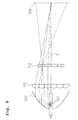
- Figure 9 shows a structure of the illumination device. Beams of light emitted by a lamp 101 provided in a parabolic mirror 102 are divided by a first lens array 110 in which lenses having substantially the same shaped aperture are arranged two-dimensionally. Thereafter, the light reaches a light-receiving surface 106 via a second lens array 112 which has lenses of the same number as the divided light beams, that is, the same number as the lenses of the first lens array 110.
- the second lens array 112 is arranged such that the light beams, which have reached thereto from a predetermined lens of the first lens array 110, pass through a corresponding lens on the second lens array 112 to reach the light-receiving surface 106 (effective area).
- the divided light beams reach the light-receiving surface 106 and are superimposed one on top of another.
- Figure 9 shows a state in which light passing through a second lens from the above of the first lens array 110 passes through a second lens from the above of the second lens array 112 , which is in a correspondence relation with the lens of the first lens array 110, and is irradiated on the light-receiving surface 106.
- the respective light beams divided by the first lens array 110 pass through respective lenses of the second lens array 112, which are in a correspondence relation with the lenses of the first lens array 110, and are superimposed one on top of another on the light-receiving surface 106.
- an arrangement of the light source images formed on the second lens array 112 is changed by adjusting (decentering) positions of center of curvature of the respective lenses in the first lens array 110.
- the positions of center of curvature of the respective lenses in the first lens array 110 are adjusted such that large useless spaces are eliminated by increasing spaces among the light source images in the vicinity of the optical axis and decreasing spaces among the light source images in the peripheral part.
- the second lens array 112 light overflowing from the apertures can be reduced by, for example, increasing sizes the apertures through which light beams in the vicinity of the optical axis are passed while keeping sizes of the apertures through which lightbeams in the peripheral part are passed.
- Higher efficiency of use of light could be obtained by optimizing a shape of the second lens array such that the respective lenses in the second lens array 112 include the respective light source images in this way (e.g., see Japanese Patent Laid-Open No. 05-346557).
- Figure 10 shows an example of an image which is formed on the second lens array 112 obtained as described above.
- the second lens array 112 is not formed in an optimal shape as described in Japanese Patent Laid-Open No. 05-346557, but a second lens array (with apertures of the same shape) having substantially the same shape as the first lens array 110 is used.
- light source images formed in the central part of the lens array 112 are light source images which are large compared with light source images formed in the peripheral part. This phenomenon will be hereinafter described with reference to Figure 11.
- an ellipsoidal mirror 2 Since an ellipsoidal mirror 2 has a focusing action like a lens, light beams irradiated from a light-emitting portion 16 of a first focus 15 are condensed in the vicinity of a second focus 17 to form an image of the light-emitting portion 16 on the second focus 17 side on a prism 4. However, an action of the ellipsoidal mirror 2 is different from an action of a lens in the following point.
- a ratio of a distance from a position of the light-emitting portion 16 to a lens surface having the focusing action and a distance from the lens surface to a position, where an image is focused is always fixed which ever position of the lens light passes.
- the ellipsoidal mirror 2 if a distance from the first focus 15, where the light-emitting portion 16 of the lamp 1 is arranged, to a reflection surface of the ellipsoidal mirror 2 having the focusing action is short, a distance from a position of the reflection surface to a second focus 17, where a light source image is formed, is long.
- a relatively large light source image is formed on the second focus 17 side on the prism 4.
- the distance from the first focus 15 to the reflection surface of the ellipsoidal mirror 2 becomes longer, the distance from the reflection surface of the ellipsoidal mirror 2 to the second focus 17 becomes shorter.
- a relatively small light source image is formed on the second focus 17 side.
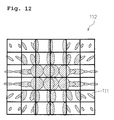
- FIG. 12 shows an example of a light source image on the second lens array formed as described above.
- Figure 12 shows an example in which there are thirty-six lenses 9, there are two light sources, and seventy-two light source images are formed on the lens array 12.
- the light source image is irradiated on an area, which should be illuminated, as an effective light beam. Therefore, in order to increase light beams which are irradiated on an area which shouldbe illuminated, as in the case of the single light source, it is conceivable to increase a size of the apertures of the respective lenses 111 in the central part of the second lens array 112.
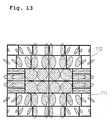
- Figure 13 shows an arrangement of images of two light sources on the second lens array 112 in the case in which irregular-shaped aperture lenses are used as the second lens array 112.
- light source images in the peripheral part of the second lens array are small images with spaces formed among the images.
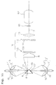
- Figure 14(a) shows paths of light beams passing through the first lens array 110 and the second lens array 112 to reach the light-receiving surface 114 in the case in which irregular-shaped aperture lenses are used as the second lens array 112.
- Light having passed through a predetermined lens 109 of the first lens array 110 reaches the entire light-receiving surface 114 serving as an area, which should be illuminated (an effective area shown in Figure 14 (a)), via the lens 111 on the second lens array 112 corresponding to the lens 109.
- light having passed through separate predetermined lens 109' of the first lens array 110 reaches the entire light-receiving surface 114 serving as an area, which should be illuminated, via a lens 111' corresponding to the lens 109'.
- the decentering of the lens 109' is adjusted so as to insert at least one light source image of a pair of light source images, which are condensed by the lens 109' separate from the predetermine lens 109 on the lens array 110, between a pair of light source images condensed by the predetermined lens 109 of the lens array 110. Therefore, at this point, the lens 111, which is one aperture having one center of curvature, includes at least three light source images.
- the center of curvature of the lens 111 in the second lens array 112 is set so as to irradiate a light beam having passed through the lens 109 of the first lens array 110 on the light-receiving surface 114 via the lens 111. Therefore, a light beam, which passes through the lens 109' to reach the lens 111 having a correspondence relation with the lens 109, cannot reach the entire light-receiving surface 114 serving as an area which should be illuminated (effective area). In other words, the light beam reaches an ineffective area shown in Figure 14(b).
- an illumination device and an illumination method which can improve efficiency of use of plural light sources, can be provided.
- the 1 st invention of the present invention is an illumination device comprising:
- the 2 nd invention of the present invention is the illumination device according to the 1 st invention of the present invention, wherein said another lens of said first lens array is formed to be decentered such that all or a part of plural images formed by said another lens are arranged among plural images formed on said second lens array by the predetermined lens of said first lens array.
- the 3 rd invention of the present invention is the illumination device according to the 2 nd invention of the present invention, wherein said second lens array is formed such that the images formed on said second lens array via said another lens of said first lens array are guided to an area, which is to be illuminated, of said light-receiving surface.
- the 4 th invention of the present invention is the illumination device according to the 3 rd invention of the present invention, wherein said second lens array is formed without a center of curvature of lenses, on which the images formed via said another lens of said first lens array are formed, on said second lens array being changed substantially.
- the 5 th invention of the present invention is the illumination device according to the 4 th invention of the present invention, wherein the plural lenses, on which the images formed via said another lens of said first lens array, on said second lens array are arranged across at least one lens on which the images formed via said predetermined lens of said first lens array.
- the 6 th invention of the present invention is the illumination device according to the 5 th invention of the present invention, wherein said plural light sources comprise a first light source and a second light source, said second lens array includes a first lens, a second lens, a third lens, and a fourth lens, the first lens and the third lens of illuminating images, which have passed through the predetermined lens of said first lens array, on said light-receiving surface are formed on said second lens array, the second lens and the fourth lens of illuminating images, which have passed through said another lens of said first lens array, on said light-receiving surface are formed on said second lens array, a center of curvature of said first lens and a center of curvature of said third lens substantially coincide with each other to form a first center of curvature, and a center of curvature of said second lens and a center of curvature of said fourth lens substantially coincide with each other to form a second center of curvature different from said first center of curvature, and said first lens, said second
- the 7 th invention of the present invention is the illumination device according to the 1 st invention of the present invention wherein, in said second lens array, an aperture of a lens close to an optical axis is formed larger than an aperture of a lens distant from the optical axis, and an aperture of a lens distant from the optical axis is formed smaller than an aperture of a lens close to the optical axis.
- the 8 th invention of the present invention is the illumination device according to the 1 st invention of the present invention, wherein said first lens array is formed such that, in a first predetermined space which is a largest space of spaces among plural images formed on said second lens array by the predetermined lens of said first array, a largest image among images formed on said second lens array with a second predetermined space, which is smaller than said first predetermined space, apart from each other by said another lens of said first lens array is arranged.
- the 9 th invention of the present invention is the illumination device according to the 8 th invention of the present invention, wherein said plural light sources comprise a first light source and a second light source, and said first lens array is formed such that a value obtained by dividing a width of an image according to a first light source, which is formed by the predetermined lens of said first lens array, by said secondpredetermined space is equal to or larger than a value found by dividing a width of an image according to a second light source, which is formed by said another lens of said first lens array, by said first predetermined space.
- the 10 th invention of the present invention is the illumination device according to the 1 st invention of the present invention, further comprising a display device of providing video information, which is arranged a predetermined space apart from said second lens array, between said second lens array and said light receiving surface.
- the 11 th invention of the present invention is an illumination method comprising:
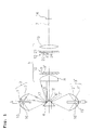
- Figure 1 shows a schematic structure of the illumination device in accordance with the embodiment of the present invention.
- the illumination device of this embodiment is constituted by including: two lamp units 3 as an example of plural light sources of the present invention which include lamps 1 and ellipsoidal mirrors 2 serving as condensing means; a triangular prism 4 as an example of reflecting means of the present invention, a side 18 of which is coated with a reflection film to form a synthesis mirror 6 as an example of a reflection surface of the present invention; a lens 8 which is arranged a predetermined space apart from the prism 4 and changes light beams, which are irradiated from the lamp units 3 and reflected on the synthesis mirror 6, to light beams substantially parallel to an optical axis of an illumination unit 5; a lens array 10 as an example of a first lens array of the present invention which is set a predetermined space apart from an outgoing side of the lens 8 and has a shape with plural lenses 9 arranged in a two-dimensional shape; a lens array 12 as an example of a second lens array of the present invention which is arranged a predetermined space apart from an outgoing side of
- a very high pressure mercury lamp in which a light-emitting material such as mercury or inert gas is enclosed in a glass tube and a pressure in the glass tube at the time of lighting rises to a very high pressure or, other than the very high pressure mercury lamp, a lamp such as a metal halide lamp, a xenon lamp, or a halogen lamp excellent in light-emitting efficiency is used.
- a light-emitting portion 16 of the lamp 1 is arranged in a first focus 15, which is one focus of the ellipsoidal mirror 2 and condenses light irradiated from the lamp 1 on a second focus 17 side which is another focus of the ellipsoidal mirror 2.
- a mirror surface of the synthesis mirror 6 is arranged in the vicinity of the second focus 17 of this ellipsoidal mirror 2 and can reflect light emitted from the ellipsoidal mirror 2 in a direction of the illumination unit 5.
- the light emitted from the ellipsoidal mirrors 2 and 2' in the vicinity of the synthesis mirrors 6 and 6' is condensed in small light source images in the vicinity of the second focuses 17 and 17' and travels expanding to the illumination unit 5 side with the vicinity of the reflection surfaces of the synthesis mirrors 6 and 6' as start points.
- the light traveling while expanding in this way is made incident on the lens 8 and is converted into light beams substantially parallel with the optical axis 7 of the illumination unit 5 to exit from the lens 8.
- the light beams having exited from the lens 8 are guided into the plural lenses 9 of the lens array 10 and divided into partial light beams.
- the divided respective partial light beams are focused on the lens array 12, which has lenses corresponding to the respective lenses in the lens array 10, in shapes similar to apertures of the respective lenses and superimposed one on top of another on the light-receiving surface 14 serving as an area, which should be illuminated, via the lens 13. Consequently, although unevenness of brightness exists in the light beams at the point when the light beams are made incident on the lens array 10, the respective partial light beams having various luminance distributions are superimposed one on top of another, whereby illumination with high uniformity is realized in the area which should be illuminated.
- the lens array 10 and the lens array 12 are arranged a space apart from each other such that the partial light beams divided by the lens array 10 are condensed in the vicinity of the lens array 12.
- the respective partial light beams condensed by the respective lenses 9 also form two light source images.
- light source images of a number which is found by multiplying the number of lenses 9 included in the lens array 10 by the number of light source images formed on the synthesis mirror 6 and the synthesis mirror 6', are formed on the lens array 12.
- lenses in the peripheral part among the lenses of the lens array 12 are divided so as to efficiently include the respective light source images.
- the lenses 9' which constitute the lens array 10 are arranged to be decentered such that light source images are formed on the divided lenses of the lens array 12.
- the lens 9' is decentered such that two light source images from the lens 9 of the lens array 10 are formed as light source images 27 and 29 on a lens 21, which is an example of a first lens of the present invention, and a lens 23, which is an example of a third lens of the present invention, of the lens array 12, respectively, and two light source images from the lens 9' separate from the lens.
- 9 are formed as light source images 28 and 30 on a lens 22, which is an example of a second lens of the present invention, and a lens 24, which is an example of a fourth lens of the present invention, of the lens array 12, respectively.
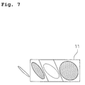
- the light source image corresponding to the lens 9 is.formed on a lens 11 (a lens having an area consisting of the lenses 21, 22 and 23 are assumed and called in this way) of the lens array 12, and the light source image corresponding to the lens 9' is formed on a lens 11' (a lens having an area consisting of the lenses 22, 23 and 24 and not overlapping the area of the lens 11 is assumed and called in this way) of the lens array 12.
- the division of the lens array 12 means that the lens 11 is divided into the lenses 21, 22 and 23 and the lens 11' is divided into the lenses 22, 23 and 24 as described above.
- the lenses of the lens array 12 are divided in this way to be arranged such that one light source image is placed between the other light source images, whereby an area of the peripheral part on the lens array 12 can be reduced (e.g. , to 4/6) compared with the second lens array 112 of the related art.
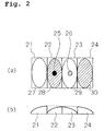
- FIG. 2(a) and (b) Such a concept of the lens division in the lens array 12 is illustrated more specifically in Figure 2(a) and (b).
- the apertures of the lenses in the peripheral part of the lens array 12 are divided into the lens 21 and the lens 23, which are apertures corresponding to a light source image from the predetermined lens 9 of the lens array 10, and the lens 22 and the lens 24, which are apertures corresponding to a light source image from separate lens 9' other than the predetermined lens 9.
- the lens 21, the lens 22, the lens 23, and the lens 24 are arranged in this order.
- a center of curvature 25, which is an example of a first center of curvature of the present invention, of the lens 21 and the lens 23 and a center of curvature 26, which is an example of a second center of curvature of the present invention, of the lens 22 and the lens 24 are arranged to be adjacent to but deviated from each other.
- a center of curvature of the lens 21 and a center of curvature of the lens 23 substantially agree with each other to form the center of curvature 25
- a center of curvature of the lens 22 and a center of curvature of the lens 24 substantially agree with each other to form the center of curvature 26.
- the center of curvature 25 and the center of curvature 26 are arranged to be deviated from each other.
- the center of curvature 25 of the lenses 21 and 23 agrees with a center of curvature of the lens 11.
- the center of curvature 26 of the lenses 22 and 24 agrees with a center of curvature of the lens 11'.
- the centers of curvature of the lenses 11 and 11' are formed without being changed substantially regardless of whether the lenses 11 and 11' are divided or not (i.e., substantially preserved before and after the division of the lenses 11 and 11').
- the centers of curvature 25 and 26, in the case in which the lenses 11 and 11' are divided are formed to agree with the center of curvature in the case in which the lenses 11 and 11' are not divided.
- Figure 2(a) shows a plan view of such lenses 21 to 24 formed on the lens array 12, and Figure 2(b) shows a sectional view thereof.
- individual light source images condensed by the lens 9 pass through the lenses 21 and 23 having the center of curvature 25, and individual light source images condensed by the lens 9' pass through the lenses 22 and 24 having the center of curvature 26.
- the light source images are efficiently irradiated as effective light beams on the light-receiving surface 14 serving as an area which should be illuminated.
- the lenses in the peripheral part of the lens array 12, in which a large gap tends to be formed between a pair of light source images formed by the lens 9 of the lens array 10, are divided, and pairs of the divided lenses have predetermined centers of curvature, respectively.
- a gap between light source images formed on the lens array 12 can be reduced, and the light source images can be included more efficiently with a small aperture than in the past.
- the light source images 27 and 29 are focused in the area formed of the lenses 21, 22 and 23 on the lens array 12, and the light source images 28 and 30 are focused in the area formed of the lenses 22, 23 and 24 which is an area separate form the area in which the area of the lenses 21, 22 and 23 is formed. Therefore, when it is assumed that areas of the lenses 21 to 24 are identical, in order to focus a light source image from the predetermined lens 9 and a light source image from the separate lens 9' on the lens array 12, an area equivalent to six lenses 21 is required.
- a light source image from the predetermined lens 9 and a light source image from the separate lens 9' can be focused on the lens array 12. Therefore, it is possible to cause an area, which can be saved in the peripheral part of the lens array 12, to contribute to an increase in apertures of the lenses in the central part of the lens array 12.
- an area of the entire lens array 12 can be made smaller than the conventional irregular-shaped aperture lenses, and miniaturization of the illumination device itself can also be realized.
- parts (gaps) on the lens array 12, where light source images are not arranged, are eliminated as much as possible, and a filling factor of light source images on the lens array 12 is increased, whereby an illumination system with higher efficiency can be realized by a smaller optical system.
- any one of the light source images in the overlapping part of the light source images does not reach an area which should be illuminated, which leads to a loss in terms of illumination efficiency.
- the number of lenses NLA2 of the lens array 12 only has to satisfy the following relation with respect to the number of lenses NLA1 of the lens array 10: (Expression 2) NLA1 ⁇ NLA2 ⁇ 2 ⁇ NLA1
- Shapes of the lens array 10 and the lens array 12 may be any shapes as long as the above (expression 2) is satisfied.
- Figure 3(a) shows an example of a shape of the lens array 10 in the case in which the number of the lenses 9 is forty-eight
- Figure 3(b) shows an example of a shape of the lens array 12, which has sixty lenses, corresponding to the lens array 10 shown in Figure 3(a).
- Figure 3 (c) shows an example of a shape of the lens array 10 in the case in which the number of the lenses 9 of the lens array 10 is forty-two
- Figure 3(d) shows an example of a shape of the lens array 12, which has forty-six lenses, corresponding to the lens array 10 shown in Figure 3 (c).
- a part of the lenses of the lens array 12 is divided in this way, whereby a size of the entire lens array 12 can be reduced to make the entire illumination device small, or sizes of the apertures of the lenses in the central part of the lens array 12 can be further increased so much more for the reduction of a gap between the pair of light source images formed in the peripheral part of the lens array 12. Thus, it becomes possible to improve efficiency of use of light.
- Figure 4 and Figure 5 show examples in which light source images, which are actually formed in the peripheral part of the lens array 12, are used.
- a width of a large light source image on a straight line connecting area centers of the respective light source images is R1
- a width of a smaller light source image is L1
- a width of a gap between the light source images is G1
- widths of a pair of light source images formed by the separate lens 9' i.e.
- light source images which would be originally formed on an imaginary lens 11' on the lens array 12 corresponding to the lens 9' in the case in which the lens 9' is assumed not to be decentered are R2 and L2, and a width of a gap between these light source images is G2.
- efficiency is better when the images are arranged such that a rate of the width (R1 or R2) of the large image with respect to the width (G1 or G2) of the gap between the respective light source images is as small as possible.
- efficiency is better with a constitution in which, rather than inserting a light source image 38 having the width L2 in the gap of G1 or inserting a light source image 37 having the width L1 in the gap of G2, a light source image 39 having the large width R1 larger than a light source image 40 having the width R2 is inserted in the gap of G2 larger than G1.
- Figure 5(a) two-dimensionally shows a part of a structure of the lens array 12 in the case in which the light source image 38 is arranged between the light source images 37 and 39
- Fig 5 (b) shows a section thereof.
- a lens 31 and a lens 33 are different lenses, these lenses have an identical center of curvature and are arranged across a lens 32.
- the lens 32 and a lens 34 are different lenses, these lenses have an identical center of curvature and are arranged across the lens 33.
- the center of curvature formed by the lenses 31 to 33 and the center of curvature formed by the lenses 32 to 34 are arranged to be adjacent to but deviated from each other.
- a constitution for inserting two or more pairs of light source images formed by plural separate lenses 9' or the like rather than a pair of light source images may be adopted.
- the respective lenses after division of the lens array 12 are arranged with positions of centers of curvature thereof adjacent to but deviated from each other in an area included in the lens 11, through which the pair of light source images pass, such that light beams from the corresponding lenses 9 and 9' or the like become effective illumination reaching an area which should be illuminated.
- the lenses 9 and 9' or the like are arranged to be decentered such that light beams passing through the lenses or the like are condensed by the lens 11.
- Figure 6(a) shows, as a plan view, a part of a structure of the lens array 12 in the case in which a light source image 51 and a light source image 52 are arranged between light source images 50 and 53
- Figure 6(b) shows a section thereof.
- a center of curvature 47 is formed by lenses 41 to 44
- a center of curvature 48 is formed by lenses 42 to 45
- a center of curvature 49 is formed by lenses 43 to 46.
- the centers of curvature 47, 48 and 49 are arranged to be adjacent to but deviated from each other.
- a center of curvature of the lens 41 and a center of curvature of the lens 44 substantially agree with each other to form the center of curvature 47
- a center of curvature of the lens 42 and a center of curvature of the lens 45 substantially agree with each other to form the center of curvature 48
- a center of curvature of the lens 43 and a center of curvature of the lens 46 substantially agree with each other to form the center of curvature 49.
- the centers of curvature 47 , 48 and 49 are arranged to be deviated from each other. However, the respective centers of curvature are formed without change regardless of whether the lens 11 is divided or not as in the case shown in Figures 2(a) and (b).
- the lens array 10 and the lens array 12 are formed so as to fill a gap between light source images with another light source image as much as possible, whereby a distance among the respective centers of curvature formed on the predetermined lens 11 on the lens array 12 can be reduced. Therefore, in that case, the size of the entire lens array 12 can be further reduced, or a diameter in the central part of the lens array 12 can be increased, whereby efficiency of use of light can be improved.
- the lens 11 may be constituted by three or two of four lenses 11.
- the lens array 12 is divided to be smaller than the lens array 10, whereby gap areas, which are generated among plural light source images formed on the lens array 12, can be reduced, and an illumination device with high efficiency of use of light can be obtained.
- the illumination device of the present invention is used, a projection display device with high efficiency of use of light can be realized.
- outward forms which are illustrated for representing sizes of light source images shown in Figures 12 and 2 (a), are indicated by equi-luminance lines having luminance of 10 to 30% in the case in which a maximum luminance in the light source image is assumed to be 100%.
- Such equi-luminance lines are indicators indicating a range in which efficiency of use of light is affected by taking in light as a light source image in the aperture of the lens 11.
- a gap or a space between plural light source images in the above description have been represented as a distance from one equi-luminance line to another equi-luminance line on a line connecting area centers of images surrounded by the equi-luminance lines.
- the space between the light source images may be defined by other methods.
- the triangular prism 4 having the synthesis mirrors 6 and 6' , the sides of which are coated with a reflective film is described as the reflectingmeans of the present invention.
- the reflecting means of the present invention is not limited to the prism 4 but may be a structure using two mirrors and may be any structure as long as the structure reflects light beams irradiated from two light sources to the illumination unit 5.
- the condensing means may be a parabolic mirror.
- a lens is used as the condensing means. In that case , since a size of a light source image does not change significantly in the central part and the peripheral part of the second lens array 12, a shape of the lens array 12 is not required to be irregular-shaped apertures.
- a constitution may be adopted in which a light source image, which is formed by the lens 9' separate from the predetermined lens 9 corresponding to the predetermined lens 11, is formed between light source images which are formed on the predetermined lens 11 in the same manner as described above. In such a case, the same effect as described above can be obtained.
- the lens 13 is illustrated as the optical means of matching light to a shape of the light-receiving surface 14 side, which should be illuminated, and converting the light into illumination light having uniformity.
- the illumination device may have a structure without the lens 13, a structure in which plural single lenses are combined, or a structure of an optical system in which optical elements such as a mirror and a prism are included.
- a liquid crystal panel 61 optical modulation device
- a projection lens 62 a projection display apparatus, which can provide a projection image with high uniformity, can be obtained.
- a structure including only one liquid crystal panel 61 as an optical modulation device is illustrated.
- a structure including plural optical modulation devices may be adopted.
- the liquid crystal panel 61 of the transmission type a transmission light bulb, a reflection light bulb, a mirror panel which can change a direction of reflection with a micro-mirror arranged in array, an optical modulation device of an optical writing system, an image display device, or the like can be used.
- the display device of the present invention is, for example, a sheet for an OHP.
- the structure using the two light sources is illustrated.
- a structure using three or more light sources may be adopted.
- the number of lenses NLA2 of the lens array 12 only has to satisfy the following relation with respect to the number of lenses 9 NLA1 of he lens array 10: (Expression 4) NLA1 ⁇ NLA2 ⁇ N ⁇ NLA1
- the structure only has to be a structure in which the lens array 10 is formed such that, in a first predetermined space which is a largest space among plural images formed on the lens array 12 by the predetermined lens 9 of the lens array 10, a largest image among images formed on the lens array 12 a second predetermined space, which is smaller than the first predetermined space, apart from each other by the lens 9' separate from the predetermined lens 9 of the lens array 10 is formed.
- a structure using a prism, a filter, a mirror, or the like, which can perform color separation and color composition may be adopted.
- the illumination device and the illumination method in accordance with the present invention efficiency of use of plural light sources can be improved.
- the illumination device and the illumination method are useful in a projection display apparatus and the like.
Landscapes
- Engineering & Computer Science (AREA)
- Multimedia (AREA)
- Signal Processing (AREA)
- Projection Apparatus (AREA)
- Non-Portable Lighting Devices Or Systems Thereof (AREA)
- Devices For Indicating Variable Information By Combining Individual Elements (AREA)
Applications Claiming Priority (3)
| Application Number | Priority Date | Filing Date | Title |
|---|---|---|---|
| JP2002299464 | 2002-10-11 | ||
| JP2002299464 | 2002-10-11 | ||
| PCT/JP2003/012927 WO2004034141A1 (ja) | 2002-10-11 | 2003-10-09 | 照明装置および照明方法 |
Publications (2)
| Publication Number | Publication Date |
|---|---|
| EP1550906A1 true EP1550906A1 (de) | 2005-07-06 |
| EP1550906A4 EP1550906A4 (de) | 2011-08-24 |
Family
ID=32089343
Family Applications (1)
| Application Number | Title | Priority Date | Filing Date |
|---|---|---|---|
| EP03807985A Withdrawn EP1550906A4 (de) | 2002-10-11 | 2003-10-09 | Illuminator und illuminationsverfahren |
Country Status (6)
| Country | Link |
|---|---|
| US (1) | US7125144B2 (de) |
| EP (1) | EP1550906A4 (de) |
| JP (1) | JP3955597B2 (de) |
| CN (1) | CN100456125C (de) |
| CA (1) | CA2482005C (de) |
| WO (1) | WO2004034141A1 (de) |
Families Citing this family (14)
| Publication number | Priority date | Publication date | Assignee | Title |
|---|---|---|---|---|
| US7224440B2 (en) * | 2004-12-23 | 2007-05-29 | Asml Netherlands B.V. | Lithographic apparatus and device manufacturing method |
| WO2006101064A1 (ja) * | 2005-03-24 | 2006-09-28 | Matsushita Electric Industrial Co., Ltd. | 撮像装置及びそれに用いられるレンズアレイ |
| TWI303010B (en) * | 2005-05-19 | 2008-11-11 | Benq Corp | Projector having a detachable light module |
| JP2009109935A (ja) * | 2007-11-01 | 2009-05-21 | Seiko Epson Corp | プロジェクタ |
| US20090153216A1 (en) * | 2007-12-12 | 2009-06-18 | International Business Machines Corporation | Io driver circuit with output stage configurable as a thevenin terminator |
| DE102008006249B4 (de) * | 2008-01-25 | 2011-04-28 | Lanz, Rüdiger | Motorisch beweglicher, kopfbewegter Scheinwerfer |
| JP4572989B2 (ja) | 2008-07-08 | 2010-11-04 | セイコーエプソン株式会社 | 照明装置、投写型表示装置、および光学インテグレータ |
| JP4516622B2 (ja) * | 2008-12-08 | 2010-08-04 | 三菱電機株式会社 | 投写型表示装置 |
| JP5245878B2 (ja) * | 2009-02-03 | 2013-07-24 | セイコーエプソン株式会社 | 照明装置及びこれを備えるプロジェクター |
| TWI404973B (zh) * | 2009-05-13 | 2013-08-11 | Coretronic Corp | 雙燈照明系統及其變焦合光裝置 |
| JP5625932B2 (ja) * | 2010-02-19 | 2014-11-19 | 株式会社Jvcケンウッド | 投射型表示装置 |
| JP6078976B2 (ja) * | 2012-04-12 | 2017-02-15 | セイコーエプソン株式会社 | プロジェクター |
| JP6369148B2 (ja) * | 2014-06-09 | 2018-08-08 | 株式会社デンソー | ヘッドアップディスプレイ装置及びその照明ユニット |
| CN105259732B (zh) * | 2015-11-18 | 2017-05-31 | 广景视睿科技(深圳)有限公司 | 一种光束合光系统及其投影装置 |
Family Cites Families (9)
| Publication number | Priority date | Publication date | Assignee | Title |
|---|---|---|---|---|
| US953105A (en) * | 1908-11-28 | 1910-03-29 | Eberhard Schneider | Optical projecting apparatus. |
| JP2973750B2 (ja) * | 1992-03-31 | 1999-11-08 | 松下電器産業株式会社 | 照明光学装置とそれを用いた投写型表示装置 |
| JP2827951B2 (ja) * | 1994-05-16 | 1998-11-25 | 松下電器産業株式会社 | 投写型表示装置 |
| JPH1166926A (ja) | 1997-08-22 | 1999-03-09 | Minolta Co Ltd | 照明装置および投影光学装置 |
| JP3301951B2 (ja) * | 1997-12-10 | 2002-07-15 | 三洋電機株式会社 | 照明装置 |
| JP2000171901A (ja) * | 1998-09-28 | 2000-06-23 | Matsushita Electric Ind Co Ltd | 照明光学装置および投写型表示装置 |
| JP4045692B2 (ja) * | 1998-10-09 | 2008-02-13 | コニカミノルタオプト株式会社 | 投射型画像表示装置 |
| JP3471001B2 (ja) | 1999-04-16 | 2003-11-25 | 富士写真光機株式会社 | 照明光学系およびこれを用いた投射型表示装置 |
| JP2001268588A (ja) | 2000-03-22 | 2001-09-28 | Matsushita Electric Ind Co Ltd | 照明装置および投写型表示装置 |
-
2003
- 2003-10-09 US US10/512,776 patent/US7125144B2/en not_active Expired - Lifetime
- 2003-10-09 CN CNB2003801004071A patent/CN100456125C/zh not_active Expired - Fee Related
- 2003-10-09 JP JP2004542851A patent/JP3955597B2/ja not_active Expired - Fee Related
- 2003-10-09 EP EP03807985A patent/EP1550906A4/de not_active Withdrawn
- 2003-10-09 CA CA2482005A patent/CA2482005C/en not_active Expired - Fee Related
- 2003-10-09 WO PCT/JP2003/012927 patent/WO2004034141A1/ja not_active Ceased
Also Published As
| Publication number | Publication date |
|---|---|
| EP1550906A4 (de) | 2011-08-24 |
| US7125144B2 (en) | 2006-10-24 |
| WO2004034141A1 (ja) | 2004-04-22 |
| JP3955597B2 (ja) | 2007-08-08 |
| CN100456125C (zh) | 2009-01-28 |
| CA2482005A1 (en) | 2004-04-22 |
| CA2482005C (en) | 2012-03-20 |
| JPWO2004034141A1 (ja) | 2006-02-09 |
| US20050225978A1 (en) | 2005-10-13 |
| CN1692307A (zh) | 2005-11-02 |
Similar Documents
| Publication | Publication Date | Title |
|---|---|---|
| JP4274766B2 (ja) | 照明装置及びその照明装置を使用した画像投影装置 | |
| US8308309B2 (en) | Lighting device and projector | |
| JP4122594B2 (ja) | 光学装置、並びに、それを用いたプロジェクタ装置、リアプロジェクタ装置及びマルチプロジェクタ装置 | |
| KR100925166B1 (ko) | 화상투사용 광학계 및 화상투사 장치 | |
| US7125144B2 (en) | Illumination device and illumination method | |
| JPH09152553A (ja) | 光源装置及びこれを用いた投写型表示装置 | |
| US20150098063A1 (en) | Illumination system, projection-type display apparatus, and optical integrator | |
| JP5206067B2 (ja) | 投射装置及び画像表示装置 | |
| CN100383600C (zh) | 光学照明系统和包括该系统的图像投影系统 | |
| EP1482358A1 (de) | Projektionsanzeigeeinrichtung | |
| WO2000038004A1 (en) | Illuminator and projection display | |
| US7648244B2 (en) | Illuminating unit and projection-type image display apparatus employing the same | |
| JP3794387B2 (ja) | 照明光学系及びプロジェクタ | |
| US7014342B2 (en) | Light guiding apparatus for an illumination system | |
| JPH11316353A (ja) | 投射型表示装置 | |
| KR20040046265A (ko) | 칼라 조명장치 및 이를 채용한 화상투사장치 | |
| JP3904597B2 (ja) | 投写型表示装置 | |
| JP4464118B2 (ja) | 照明光学系及びそれを有する画像表示装置 | |
| US7204613B2 (en) | Projection display device | |
| JP5097042B2 (ja) | 照明光学装置及びそれを用いた投写型表示装置 | |
| JP2010026260A (ja) | 照明光学装置及びそれを用いた投写型表示装置 | |
| KR100930238B1 (ko) | 조명 장치 및 소형 프로젝션 시스템 | |
| JP2002373503A (ja) | 照明装置及び投写型表示装置 | |
| JP5311880B2 (ja) | 光源装置およびそれを用いた画像表示装置 | |
| US7798654B2 (en) | Image display apparatus |
Legal Events
| Date | Code | Title | Description |
|---|---|---|---|
| PUAI | Public reference made under article 153(3) epc to a published international application that has entered the european phase |
Free format text: ORIGINAL CODE: 0009012 |
|
| 17P | Request for examination filed |
Effective date: 20050428 |
|
| AK | Designated contracting states |
Kind code of ref document: A1 Designated state(s): AT BE BG CH CY CZ DE DK EE ES FI FR GB GR HU IE IT LI LU MC NL PT RO SE SI SK TR |
|
| RBV | Designated contracting states (corrected) |
Designated state(s): BE DE GB |
|
| RAP1 | Party data changed (applicant data changed or rights of an application transferred) |
Owner name: PANASONIC CORPORATION |
|
| A4 | Supplementary search report drawn up and despatched |
Effective date: 20110727 |
|
| RIC1 | Information provided on ipc code assigned before grant |
Ipc: G02B 19/00 20060101ALI20110721BHEP Ipc: G03B 21/00 20060101AFI20110721BHEP |
|
| 17Q | First examination report despatched |
Effective date: 20120416 |
|
| STAA | Information on the status of an ep patent application or granted ep patent |
Free format text: STATUS: THE APPLICATION HAS BEEN WITHDRAWN |
|
| 18W | Application withdrawn |
Effective date: 20131111 |