EP1550599B1 - Collision energy absorbing steering column device - Google Patents
Collision energy absorbing steering column device Download PDFInfo
- Publication number
- EP1550599B1 EP1550599B1 EP03799083A EP03799083A EP1550599B1 EP 1550599 B1 EP1550599 B1 EP 1550599B1 EP 03799083 A EP03799083 A EP 03799083A EP 03799083 A EP03799083 A EP 03799083A EP 1550599 B1 EP1550599 B1 EP 1550599B1
- Authority
- EP
- European Patent Office
- Prior art keywords
- energy
- absorbing
- steering column
- load
- secondary collision
- Prior art date
- Legal status (The legal status is an assumption and is not a legal conclusion. Google has not performed a legal analysis and makes no representation as to the accuracy of the status listed.)
- Expired - Lifetime
Links
- 238000010521 absorption reaction Methods 0.000 claims description 113
- 238000006073 displacement reaction Methods 0.000 claims description 55
- 230000008859 change Effects 0.000 claims description 10
- 230000007246 mechanism Effects 0.000 description 90
- 230000002787 reinforcement Effects 0.000 description 49
- XEEYBQQBJWHFJM-UHFFFAOYSA-N Iron Chemical compound [Fe] XEEYBQQBJWHFJM-UHFFFAOYSA-N 0.000 description 36
- 230000009471 action Effects 0.000 description 28
- 229910052742 iron Inorganic materials 0.000 description 18
- 230000007704 transition Effects 0.000 description 5
- 230000004044 response Effects 0.000 description 4
- 241001232202 Chrysothamnus stylosus Species 0.000 description 3
- 238000003780 insertion Methods 0.000 description 3
- 230000037431 insertion Effects 0.000 description 3
- 230000000694 effects Effects 0.000 description 2
- 229910000831 Steel Inorganic materials 0.000 description 1
- 239000006096 absorbing agent Substances 0.000 description 1
- 238000005452 bending Methods 0.000 description 1
- 239000002184 metal Substances 0.000 description 1
- 229910052751 metal Inorganic materials 0.000 description 1
- 230000004048 modification Effects 0.000 description 1
- 238000012986 modification Methods 0.000 description 1
- 210000003254 palate Anatomy 0.000 description 1
- 239000007787 solid Substances 0.000 description 1
- 239000010959 steel Substances 0.000 description 1
Images


Classifications
-
- F—MECHANICAL ENGINEERING; LIGHTING; HEATING; WEAPONS; BLASTING
- F16—ENGINEERING ELEMENTS AND UNITS; GENERAL MEASURES FOR PRODUCING AND MAINTAINING EFFECTIVE FUNCTIONING OF MACHINES OR INSTALLATIONS; THERMAL INSULATION IN GENERAL
- F16F—SPRINGS; SHOCK-ABSORBERS; MEANS FOR DAMPING VIBRATION
- F16F7/00—Vibration-dampers; Shock-absorbers
- F16F7/12—Vibration-dampers; Shock-absorbers using plastic deformation of members
- F16F7/128—Vibration-dampers; Shock-absorbers using plastic deformation of members characterised by the members, e.g. a flat strap, yielding through stretching, pulling apart
-
- B—PERFORMING OPERATIONS; TRANSPORTING
- B62—LAND VEHICLES FOR TRAVELLING OTHERWISE THAN ON RAILS
- B62D—MOTOR VEHICLES; TRAILERS
- B62D1/00—Steering controls, i.e. means for initiating a change of direction of the vehicle
- B62D1/02—Steering controls, i.e. means for initiating a change of direction of the vehicle vehicle-mounted
- B62D1/16—Steering columns
- B62D1/18—Steering columns yieldable or adjustable, e.g. tiltable
- B62D1/184—Mechanisms for locking columns at selected positions
-
- B—PERFORMING OPERATIONS; TRANSPORTING
- B62—LAND VEHICLES FOR TRAVELLING OTHERWISE THAN ON RAILS
- B62D—MOTOR VEHICLES; TRAILERS
- B62D1/00—Steering controls, i.e. means for initiating a change of direction of the vehicle
- B62D1/02—Steering controls, i.e. means for initiating a change of direction of the vehicle vehicle-mounted
- B62D1/16—Steering columns
- B62D1/18—Steering columns yieldable or adjustable, e.g. tiltable
- B62D1/19—Steering columns yieldable or adjustable, e.g. tiltable incorporating energy-absorbing arrangements, e.g. by being yieldable or collapsible
- B62D1/195—Yieldable supports for the steering column
Definitions
- the present invention relates to an impact-absorbing steering column apparatus according to the preamble of claim 1 of the invention having collision-energy-absorbing means for absorbing secondary collision energy of an occupant (driver) in the event of a collision of a vehicle.
- EP 0 655 383 discloses such a steering column, including the features of the preamble of claim 1.
- a conventional impact-absorbing steering column apparatus effects absorption of secondary collision energy such that column drive means causes a steering column to retreat in relation to an occupant in accordance with the distance between the occupant and a steering wheel or the position of the steering column in relation to the occupant or such that energy absorption quantity adjustment means varies, in accordance with the distance or the position, the quantity of secondary impact energy to be absorbed by collision-energy-absorbing means.
- Such an impact-absorbing steering column apparatus is disclosed in, for example, Japanese Patent Application Laid-Open ( kokai ) No. 2002-79944 .
- the above-mentioned conventional impact-absorbing steering column apparatus is configured such that the column drive means and the energy absorption quantity adjustment means are operated under the control of an electrical control unit.
- the distance between the occupant and the steering wheel or the position of the steering column in relation to the occupant is electrically detected.
- the column drive means or the energy absorption quantity adjustment means is electrically controlled.
- US-B1-6 322 103 describes an actively variable energy absorber for a steering column, which counteracts a linear translation of a steering column housing in the direction of the centerline of the steering column due to a collision of a driver with a steering wheel. Thereby, the driver is decelerated by converting the kinetic energy of his motion into deformation energy of a flat metal strap being bent by means of a counterpart.
- the present invention has been accomplished in order to solve the above problem, and an object of the invention is to change an absorption load for secondary collision energy of an occupant in the event of a secondary collision of the occupant with a steering system, by means of a mechanical action effected by the secondary collision.
- This object is achieved by an impact-absorbing steering column apparatus with the features of claim 1 of the invention.
- An aspect of the present invention provides an impact-absorbing steering column apparatus comprising collision-energy-absorbing means for absorbing secondary collision energy of an occupant in the event of a collision of a vehicle.
- the collision-energy-absorbing means comprises energy-absorption-load-changing means for changing an absorption load for the secondary collision energy.
- the energy-absorption-load-changing means is adapted to change the absorption load in accordance with displacement of a steering column, the displacement changing dependently on a secondary collision of the occupant with a steering system.
- the occupant moves in a certain direction toward the front of the vehicle while having certain kinetic energy, depending on whether or not the occupant wears a seat belt, a collision speed, a seat position, and like factors; and a certain secondary collision load is input to the steering system along a certain direction of a secondary collision.
- the energy-absorption-load-changing means of the collision-energy-absorbing means can change the absorption load for secondary collision in accordance with displacement of the steering column, the displacement changing dependently on a secondary collision of the occupant with the steering system.
- the steering column in accordance with the direction of the secondary collision of the occupant with the steering system and/or the magnitude of the collision load, the steering column is displaced or allowed to be readily displaced in a direction different from a direction along which the steering column moves in relation to the vehicle body toward the front of the vehicle while absorbing energy.
- an absorption load to be generated by the energy-absorption-load-changing means can be changed in accordance with the displacement of the steering column.
- an impact-absorbing steering column apparatus comprising collision-energy-absorbing means for absorbing secondary collision energy of an occupant in the event of a collision of a vehicle.
- the collision-energy-absorbing means comprises energy-absorption-load-changing means for changing an absorption load for the secondary collision energy.
- the energy-absorption-load-changing means is adapted to change the absorption load in accordance with displacement of the steering column in a direction intersecting a direction of relative movement of the steering column for absorbing collision energy induced by a secondary collision of the occupant.
- the occupant moves in a certain direction toward the front of the vehicle while having certain kinetic energy, depending on whether or not the occupant wears a seat belt, a collision speed, a seat position, and like factors; and a certain secondary collision load is input to the steering system along a certain direction of a secondary collision.
- the energy-absorption-load-changing means adapted to absorb energy can change an absorption load.
- the steering column in accordance with the direction of the secondary collision of the occupant with the steering system and/or the magnitude of the collision load, the steering column is displaced or allowed to be readily displaced in a direction different from a direction along which the steering column moves in relation to the vehicle body toward the front of the vehicle while absorbing energy.
- the energy-absorption-load-changing means changes the absorption load in accordance with a mode of displacement of the steering column.
- an absorption load to be generated by the energy-absorption-load-changing means is changed in accordance with a mode of displacement of the steering column, so that the absorption load can be changed in accordance with the displaced position of the steering column.
- the energy-absorption-load-changing means comprises an energy-absorbing member, and engagement means capable of engaging with the energy-absorbing member, and an engagement relation between the energy-absorbing member and the engagement means varies in accordance with a mode of displacement of the steering column, thereby changing the absorption load.
- the engagement relation between the energy-absorbing member and the engagement means can be varied in accordance with a mode of displacement of the steering column, whereby the absorption load can be changed.
- the engagement means is squeezing means for squeezing the energy-absorbing member; the energy-absorbing member has an energy-absorbing portion, which is squeezed by the squeezing means to thereby absorb energy; and an engagement relation between the squeezing means and the energy-absorbing portion varies in accordance with a mode of displacement of the steering column, thereby changing the absorption load.
- the engagement relation between the squeezing means and the energy-absorbing portion is varied in accordance with a mode of displacement of the steering column, whereby the absorption load can be changed.
- the engagement means is squeezing means for squeezing the energy-absorbing member;
- the energy-absorbing member has a plurality of energy-absorbing portions that differ in energy absorption load in relation to the squeezing means; and an engagement between the squeezing means and one of the plurality of energy-absorbing portions is selected in accordance with a mode of displacement of the steering column, thereby changing the absorption load.
- an engagement between the squeezing means and one of the plurality of energy-absorbing portions is selected in accordance with a mode of displacement of the steering column, whereby the absorption load can be changed.
- the engagement means is squeezing means for squeezing the energy-absorbing member; the squeezing means has a plurality of squeezing portions that differ in the quantity of draw/squeeze in squeezing the energy-absorbing member; and an engagement between the energy-absorbing member and one of the plurality of squeezing portions is selected in accordance with a mode of displacement of the steering column, thereby changing the absorption load.
- an engagement between the squeezing means and one of the plurality of squeezing portions is selected in accordance with a mode of displacement of the steering column, whereby the absorption load can be changed.
- the energy-absorbing member is a linear member capable of engaging with the engagement means; the engagement means is engaged with or is not engaged with the linear member in accordance with a mode of displacement of the steering column, thereby changing the absorption load.
- the engagement means is engaged with or is not engaged with the linear member in accordance with a mode of displacement of the steering column, whereby the absorption load can be changed.
- the energy-absorbing member is a plurality of linear members capable of engaging with the engagement means; the number of the linear members to be engaged with the engagement means varies in accordance with a mode of displacement of the steering column, thereby changing the absorption load.
- the number of the linear members to be engaged with the engagement means varies in accordance with a mode of displacement of the steering column, whereby the absorption load can be changed.
- the steering column comprises the energy-absorbing member, a ball adapted to plastically deform the energy-absorbing member, and ball support means for adjusting the quantity of plastic deformation to be effected by the ball; and the ball support means is moved in accordance with a mode of displacement of the steering column in such a manner as to vary an engagement relation between the energy-absorbing member and the ball in accordance with the mode, thereby changing the absorption load.
- the ball support means is moved in such a manner as to vary the engagement relation between the energy-absorbing member and the ball in accordance with a mode of displacement of the steering column, whereby the absorption load can be changed.
- the energy-absorbing member has an elongated groove having a predetermined width;
- the engagement means is squeezing means assuming a special shape and capable of being displaced in the elongated groove in relation to the energy-absorbing member; and an engagement relation between the special-shape squeezing means and the elongated groove of the energy-absorbing member varies in accordance with a mode of displacement of the steering column, thereby changing the absorption load.
- the engagement relation between the special-shape squeezing means and the elongated groove of the energy-absorbing member varies in accordance with a mode of displacement of the steering column, whereby the absorption load can be changed.
- an energy-absorbing member is provided on either a vehicle-body-side member or the steering column, the energy-absorbing member generating an energy absorption load by means of displacement in relation to either the vehicle-body-side member or the steering column on which the energy-absorbing member is provided; the engagement means capable of engaging with the energy-absorbing member is provided on either the vehicle-body-side member or the steering column on which the energy-absorbing member is not provided; and when the energy-absorbing member is engaged with the engagement means in accordance with a mode of displacement of the steering column, the mode changing dependently on a secondary collision, the energy-absorbing member incrementally changes the absorption load by means of displacement in relation to either the vehicle-body-side member or the steering column on which the energy-absorbing member is provided.
- the energy-absorbing member when the energy-absorbing member is engaged with the engagement means in accordance with a mode of displacement of the steering column, the mode of displacement changing dependently on a secondary collision, the energy-absorbing member can incrementally change the absorption load by means of displacement in relation to either the vehicle-body-side member or the steering column on which the energy-absorbing member is provided.
- the energy-absorption-load-changing means changes the absorption load in accordance with displacement of the steering column, the displacement changing dependently on the direction of a secondary collision of the occupant with the steering system.
- the energy-absorption-load-changing means can change the absorption load in accordance with displacement of the steering column, the displacement changing dependently on the direction of a secondary collision of the occupant with the steering system.
- the energy-absorption-load-changing means changes the absorption load in accordance with displacement of the steering column, the displacement changing dependently on the direction of a secondary collision of the occupant with the steering system at an initial stage of the secondary collision.
- the energy-absorption-load-changing means can change the absorption load in accordance with displacement of the steering column, the displacement changing dependently on the direction of a secondary collision of the occupant with the steering system at an initial stage of the secondary collision.
- the energy-absorption-load-changing means when a collision load associated with a secondary collision of the occupant with the steering system is equal to or greater than a predetermined value, the energy-absorption-load-changing means increases the absorption load.
- the energy-absorption-load-changing means can increase the absorption load.
- the energy-absorption-load-changing means increases the absorption load in accordance with such displacement that the steering column tilts upward as a result of a secondary collision of the occupant with the steering system.
- the energy-absorption-load-changing means can increase the absorption load in accordance with such displacement that the steering column tilts upward as a result of a secondary collision of the occupant with the steering system.
- the energy-absorption-load-changing means changes the absorption load in accordance with a direction of displacement of the steering column, the direction of displacement changing dependently on the direction of a secondary collision of the occupant with the steering system.
- the energy-absorption-load-changing means can increase the absorption load in accordance with the displaced position of the steering column, the displaced position changing dependently on the direction of a secondary collision of the occupant with the steering system.
- impact-absorbing means for absorbing a predetermined collision load is provided separately from the collision-energy-absorbing means.
- the impact-absorbing means for absorbing a predetermined collision load can be provided separately from the collision-energy-absorbing means.
- the collision-energy-absorbing means selectively provides the absorption load, or changes the magnitude of the absorption load.
- the collision-energy-absorbing means can determine whether to effect the absorption load or can change the magnitude of the absorption load.
- the loads changing dependently on a secondary collision of the occupant with the steering system
- deformation of an energy-absorbing member provided on either the steering column or the vehicle-body-side member is passively changed by engagement means provided on either the steering column or the vehicle-body-side member on which the energy-absorbing member is not provided, whereby the energy-absorption-load-changing means changes the absorption load.
- the loads changing dependently on a secondary collision of the occupant with the steering system
- deformation of the energy-absorbing member provided on either the steering column or the vehicle-body-side member is passively changed by the engagement means provided on either the steering column or the vehicle-body-side member on which the energy-absorbing member is not provided, whereby the absorption load can be changed.
- the engagement means is formed on the vehicle-body-side member; the energy-absorbing member is provided on the steering column in opposition to the engagement means and assumes an elongated shape extending along an axis of the steering column; and the engagement means provided on the vehicle-body-side member causes the deformation of the energy-absorbing member provided on the steering column.
- the engagement means is formed on the vehicle-body-side member; the energy-absorbing member is provided on the steering column in opposition to the engagement means and assumes an elongated shape extending along the axis of the steering column; and the engagement means provided on the vehicle-body-side member can cause the deformation of the energy-absorbing member provided on the steering column.
- abutment between the engagement means and the energy-absorbing member is enabled.
- the engagement means can abut the energy-absorbing member.
- the steering column in the event of a secondary collision, is allowed to be displaced in such a manner as to tilt toward the vehicle-body-side member.
- the steering column can be displaced in such a manner as to tilt toward the vehicle-body-side member.
- the absorption load is increased with a load of pressing the steering column against the vehicle-body-side member.
- the absorption load can be increased with the load of pressing the steering column against the vehicle-body-side member.
- impact-absorbing means for absorbing a predetermined collision load is provided separately from the collision-energy-absorbing means.
- the impact-absorbing means for absorbing a predetermined collision load can be provided separately from the collision-energy-absorbing means.
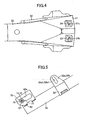
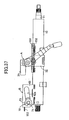
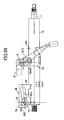
- FIGS. 1 to 8 show a first embodiment of an impact-absorbing steering column apparatus according to the present invention.
- a steering column 12 supports a steering shaft 11 rotatably and in an axially unmovable condition and is supported by a steering mounting member 20, which is a portion of a vehicle body, at a predetermined tilt angle by means of an upper support mechanism A and a lower support mechanism B.
- the lower end (front end) of the steering shaft 11 is linked to an intermediate shaft 14, which can extend and contract and can transmit torque, via a universal joint 13.
- a steering wheel 17, into which an airbag device is incorporated, is attached to the upper end (rear end) of the steering shaft 11 in a unitarily rotatable condition.
- the upper support mechanism A is adapted to support an upper region of the steering column 12.
- the upper support mechanism A supports the upper region of the steering column 12 such that the steering column 12 can be vertically moved for adjustment (the tilt of the steering column 12 can be adjusted).
- the upper support mechanism A supports the upper region of the steering column 12 such that the steering column 12 can tilt upward and can move frontward along its axis.
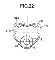
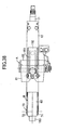
- the upper support mechanism A includes a support bracket 31 made of an iron plate, a column-side bracket 32 made of an iron plate, clamp means 40, and an operation lever 50 used to operate the clamp means 40.
- the support bracket 31 has laterally paired arms 31a and 31b extending downward and is fixedly attached to the steering mounting member 20 by use of laterally paired mounting bolts 39.
- the column-side bracket 32 has laterally paired arms 32a and 32b extending upward and is welded to the steering column 12.
- the clamp means 40 is adapted to frictionally engage the arms 32a and 32b of the column-side bracket 32 with the arms 31 a and 31 b of the support bracket 31 in a fixed condition or to disengage them.
- the steering mounting member 20 has a mounting portion 21 in its upper region for attachment of the upper support mechanism A and a mounting portion 22 in its lower region for attachment of the lower support mechanism B.
- the mounting portion 21 for the upper support mechanism A has a substantially U-shaped cross section, and a substantially V-shaped convex surface S1 located at its lower end.
- Laterally paired bolt insertion holes 21 b and 21 c are formed in the mounting portion 21 and allow the corresponding mounting bolts 39 to extend therethrough.
- Laterally paired nuts 23 and 24 into which the corresponding mounting bolts 39 are screwed are welded to the mounting portion 21 in alignment with the bolt insertion holes 21 b and 21 c, respectively.
- the support bracket 31 is composed of a plate 31A and a reinforcement plate 31B.
- the plate 31A has a substantially M-shaped cross section, and a substantially V-shaped concave surface S2 located at its top and coming into close contact with the substantially V-shaped convex surface S1 of the steering mounting member 20.
- the reinforcement plate 31 B is welded to laterally opposite lower end portions of the plate 31A so as to reinforce the plate 31A.
- the plate 31A includes the laterally paired arms 31 a and 31 b extending downward. Laterally paired bolt insertion holes 31 c (see FIG. 6 ) are formed in the plate 31A and allow the corresponding mounting bolts 39 to extend therethrough.
- laterally paired guide slots 31a1 and 31b1 extending frontward and laterally paired guide slots 31a2 and 31b2 extending frontward are formed in the arms 31a and 31b.
- the lower guide slots 31a1 and 31b1 are formed linearly, substantially in parallel with the axial direction of the steering column 12.
- the lower guide slots 31a1 and 31b1 and the corresponding upper guide slots 31a2 and 31b2 communicate with each other via corresponding transition portions 31a3 and 31b3 located at rear end portions of the guide slots.
- the upper guide slots 31a2 and 31b2 are formed linearly and extend upward at a predetermined angle ⁇ with respect to the corresponding lower guide slots 31 a1 and 31b1.
- the column-side bracket 32 includes the laterally paired arms 32a and 32b, which extend upward and are slidably engaged with the corresponding arms 31 a and 31 b of the support bracket 31 from the outside.
- Arcuately elongated holes 32a1 and 32b1 are formed in the corresponding arms 32a and 32b arcuately about support center O1 of the lower support mechanism B.
- the clamp means 40 includes a nonrotatable lock bolt 41, a collar 42, a nut 43, and a pair of laterally adjacent cam plates 44.
- the lock bolt 41 extends through the arcuately elongated holes 32a1 and 32b1 formed in the laterally opposite arms 32a and 32b of the column-side bracket 32 and through the guide slots 31a1 and 31 b1 or the guide slots 31a2 and 31b2 formed respectively in the laterally opposite arms 31 a and 31 b of the support bracket 31.
- the collar 42 is fitted onto the lock bolt 41 while extending between the laterally opposite arms 32a and 32b of the column-side bracket 32 and is fitted, at its laterally opposite end portions, into the guide slots 31a1 and 31b1 or the guide slots 31 a2 and 32b2.
- the nut 43 is screwed on an externally threaded portion 41 a of the lock bolt 41 and rotated by means of the operation lever 50.
- the paired cam plates 44 are mounted on the lock bolt 41 between the operation lever 50 and the left arm 32a of the column-side bracket 32.
- the detailed configuration of the paired, laterally adjacent cam plates 44 is the same as hat described in Japanese Patent Application Laid-Open ( kokai ) No. 2000-62624 ; therefore, repeated description thereof is omitted.
- the clamp means 40 functions as follows.
- the operation lever 50 is rotated counterclockwise in FIG. 1
- the nut 43 is fastened to the lock bolt 41
- the paired cam plates 44 convert rotation of the operation lever 50 to an axial stroke of the lock bolt 41.
- a predetermined frictional engagement is established between the arms 31 a and 32a of the brackets 31 and 32 and between the arms 31 b and 32b of the brackets 31 and 32, whereby the column-side bracket 32 is fixed (locked) to the support bracket 31.
- the operation lever 50 is rotated clockwise in FIG. 1
- the nut 43 is loosened, and thus the above frictional engagement is canceled.
- the column-side bracket 32 becomes tiltable in relation to the support bracket 31.
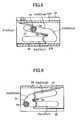
- a support plate 35 is attached to the support bracket 31, and vertically paired energy-absorbing members 36 and 37 are also attached to the support bracket 31.
- the support plate 35 extends laterally within the support bracket 31 and is welded, at its laterally opposite ends, to the arms 31 a and 31 b of the support bracket 31.
- the lower energy-absorbing member 36 is provided for use with the lower guide slots 31a1 and 31b1, and is a thin elongated plate having a predetermined width (a plate whose absorption load is small when absorbing secondary collision energy).
- a predetermined width a plate whose absorption load is small when absorbing secondary collision energy.
- the upper energy-absorbing member 37 is provided for use with the upper guide slots 31a2 and 31b2, and is a thick elongated plate having a predetermined width (a plate whose absorption load is large when absorbing secondary collision energy).
- a predetermined width a plate whose absorption load is large when absorbing secondary collision energy.
- the lower support mechanism B is adapted to support a lower region of the steering column 12.
- the lower support mechanism B supports the lower region of the steering column 12 in a tiltable (pivotable) condition.
- the lower support mechanism B supports the steering column 12 such that the steering column 12 can move frontward along its axis.
- the lower support mechanism B is composed of a vehicle-body-side bracket 61 made of an iron plate, a column-side bracket 62 made of an iron plate, and connection means 70.
- the vehicle-body-side bracket 61 includes laterally paired arms 61 a extending downward and is fixed to the steering mounting member 20.
- the column-side bracket 62 has a cross section resembling a squarish letter U and is welded to the steering column 12 at an upper portion of the column's outer circumferential surface in the column's lower region.
- the connection means 70 connects the column-side bracket 62 to the vehicle-body-side bracket 61 such that the column-side bracket 62 is movable along the column axis and tiltable.
- the connection means 70 is composed of laterally paired resin bushes 71 and 72, a collar 73, a bolt 74, and a nut (welded to the right-hand arm of the vehicle-body-side bracket 61), into which the bolt 74 is screwed in a fixed condition.
- the bushes 71 and 72 are fitted to corresponding laterally paired elongated holes 62a formed in the column-side bracket 62 and extending along the column axis and break under a predetermined load.
- the collar 73 is fitted into the resin bushes 71 and 72 and engaged, at its opposite ends, with the arms 61 a of the vehicle-body-side bracket 61.
- the bolt 74 extends through the collar 73 and through round mounting holes formed in the corresponding arms 61 a of the vehicle-body-side bracket 61 and unites the resin bushes 71 and 72 and the collar 73 with the vehicle-body-side bracket 61.
- a seat belt device 90 is attached to a seat 80 for an occupant H.
- the seat belt device 90 includes a seat belt 91, a tongue plate 92, a buckle 93, and a shoulder belt anchor 94, as well as a retractor 95 into which a pretensioner mechanism and a force limiter mechanism are incorporated.
- the seat belt 91 can restrain the occupant H.
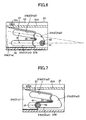
- the first embodiment functions as follows. Since the occupant H is restrained by the seat belt 91, the occupant H moves frontward while bending himself/herself forward. At the initial stage of a secondary collision of this case, a collision load from the occupant H is exerted on the steering column 12 in the direction of F1 (along the axis of the steering column 12) in FIG. 2 via the steering wheel 17 and the steering shaft 11. As a result of the collision load overcome the above-mentioned frictional engagement and a rupture load of the bushes 71 and 72, the steering column 12 moves frontward along its axial direction.
- the lock bolt 41 and the collar 42 in the upper support mechanism A move frontward along the guide slots 31a1 and 31b1, thereby plastically deforming the lower energy-absorbing member 36.
- the plastic deformation yields a small absorption load for secondary collision energy.
- the seat belt device 90 functions; and an air bag device incorporated in the steering wheel 17, and the energy-absorbing member 36, which is provided for use with the lower guide slots 31a1 and 31b1 in the upper support mechanism A, function sequentially, thereby absorbing secondary collision energy of the occupant H.
- the lock bolt 41 and the collar 42 move from rear end portions of the lower guide slots 31 a1 and 31b1 to rear end portions of the upper guide slots 31a2 and 31b2 via the transition portions 31a3 and 31b3. Subsequently, as shown in FIG. 8 , the lock bolt 41 and the collar 42 move frontward along the upper guide slots 31a2 and 31b2, thereby plastically deforming the upper energy-absorbing member 37. The plastic deformation yields a large absorption load for secondary collision energy.
- the air bag device incorporated in the steering wheel 17, and the energy-absorbing member 37 which is provided for use with the upper guide slots 31a2 and 31b2 in the upper support mechanism A, function sequentially, thereby absorbing secondary collision energy of the occupant H.
- the steering column 12 in the event of a collision of the vehicle, in accordance with, for example, whether or not the occupant H wears the seat belt 91, the occupant H moves frontward in a certain direction while having certain kinetic energy; and a certain secondary collision load (for example, F1 or F2) is input to the steering column 12 along a certain direction of a secondary collision.
- a certain secondary collision load for example, F1 or F2
- the steering column 12 is displaced in the direction of the secondary collision while being guided by the guide slots provided in the support bracket 31; specifically, by the guide slots 31a1 and 31b1, the guide slots 31a2 and 31b2, and the transition portions 31a3 and 31b3.
- the displacement causes the energy-absorbing member 36 provided for use with the guide slots 31a1 and 31b1 or the energy-absorbing member 37 provided for use with the guide slots 31a2 and 31b2 to function, whereby in the event of a secondary collision an absorption load for secondary collision energy is changed.
- energy-absorption-load-changing means including the guide slots 31a1 and 31 b1, the guide slots 31a2 and 31b2, and the transition portions 31a3 and 31b3 provided in the support bracket 31 changes the absorption load by means of a mechanical action effected in accordance with the direction of a secondary collision of the occupant H with the steering system.
- the first embodiment can be mechanically implemented by means of appropriately setting, for example, the shape of the guide slots 31a1 and 31b1, the shape of the guide slots 31a2 and 31b2, the shape of the transition portions 31a3 and 31b3, and the shape of the energy-absorbing members 36 and 37, without need to employ electrical control, whose cost is high, and thus at low cost.
- the lower energy-absorbing member 36 is formed of a thin, elongated plate having a predetermined width
- the upper energy-absorbing member 37 is formed of a thick, elongated plate having a predetermined width
- the energy-absorbing members 36 and 37 may be embodied as follows: the lower energy-absorbing member 36 is formed of a narrow, elongated plate having a predetermined thickness, and the upper energy-absorbing member 37 is formed of a wide, elongated plate having the predetermined thickness.
- the present invention is embodied in relation to a steering column assembly having a tilt function.
- the present invention may be similarly embodied in relation to a steering column assembly having no tilt function.
- two pairs of guide slots 31a1 and 31b1, and 31a2 and 31b2 are provided in the support bracket 31, and the energy-absorbing members 36 and 37 are provided for use with the corresponding guide slots.
- the number of guide slots and the number of energy-absorbing members may be increased as appropriate.
- two pairs of guide slots 31a1 and 31b1, and 31a2 and 31b2, and two kinds of corresponding energy-absorbing members 36 and 37 are provided in the support bracket 31, which is a vehicle-body-side member in the upper support mechanism A.
- the following configuration may be employed: two guide means are provided in the column-side bracket 32, which is a column-side member in the upper support mechanism A, and two kinds of energy-absorbing members are provided which correspond to these guide means.
- a support shaft (a member corresponding to the lock bolt 41) is fixedly attached to a vehicle-body-side support bracket.
- collision-energy-absorbing means which includes two pairs of guide slots 31a1 and 31b1, and 31a2 and 31b2, and two kinds of energy-absorbing members 36 and 37
- the collision-energy-absorbing means which includes two pairs of guide slots 31a1 and 31b1, and 31a2 and 31b2, and two kinds of energy-absorbing members 36 and 37
- the lower support mechanism B is provided in the lower support mechanism B.
- the rear end of the energy-absorbing member 36 is welded to the upper surface of the steering column 12
- the rear end of the energy-absorbing member 37 is welded to the lower surface of the upper wall of the column-side bracket 62.
- the energy-absorbing members 36 and 37 which are plastically deformed by means of the lock bolt 41 and the collar 42 to thereby absorb secondary collision energy, are formed of corresponding elongated plates provided separately from the support bracket 31.
- the following configuration may be employed: the guide slots 31a1 and 31b1 and the guide slots 31a2 and 31b2 formed in the support bracket 31 assume different widths such that the guide slot portions are plastically deformed by means of the lock bolt 41 and the collar 42 to thereby absorb secondary collision energy.
- the present invention is embodied in relation to a steering column assembly configured such that an upper region of the steering column 12 is supported by the upper support mechanism A in a frontward movable condition, and a lower region of the steering column 12 is supported by the lower support mechanism B in a frontward movable condition.
- the present invention may be similarly embodied in relation to a steering column assembly configured such that a steering column is supported by a single support mechanism in a frontward movable condition.
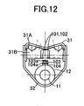
- FIGS. 10 to 14 show a second embodiment of the impact-absorbing steering column apparatus according to the present invention.
- collision-energy-absorbing means for absorbing secondary collision energy of the occupant H includes laterally paired energy-absorbing members 101 and 102 provided in the upper support mechanism A, engagement pins 103 and 104 provided on the steering column 12, and an energy-absorbing member 105 provided in the lower support mechanism B.
- Structural features other than the collision-energy-absorbing means for absorbing secondary collision energy of the occupant H are substantially identical with those of the above-described first embodiment and are thus denoted by common reference numerals, and repeated description thereof is omitted.
- the laterally paired energy-absorbing members 101 and 102 are elongated plates. When the engagement pin 103 or 104 is engaged with the energy-absorbing members 101 and 102 and passes frontward therebetween, the energy-absorbing members 101 and 102 are plastically deformed to thereby absorb secondary collision energy.
- the energy-absorbing members 101. and 102 are formed integrally with the reinforcement plate 31 B of the support bracket 31 in the upper support mechanism A.
- the energy-absorbing members 101 and 102 face each other with a predetermined gap formed therebetween and extend along the axial direction of the steering column 12.
- the engagement pins 103 and 104 are provided on the steering column 12 in such a manner as to project upward. Stoppers 103a and 104a are integrally formed at distal end portions of the engagement pins 103 and 104, respectively. The main purpose of the stoppers 103a and 104a is to prevent the engagement pin 103 or 104 from coming out of the gap between the energy-absorbing members 101 and 102 when the engagement pin 103 or 104 is fitted into the gap and moves frontward through the gap.
- the distal engagement pin 103 has a diameter slightly greater than the gap between the energy-absorbing members 101 and 102.
- the engagement pin 103 can be fitted into the gap between the energy-absorbing members 101 and 102.
- the engagement pin 103 fitted into the gap between the energy-absorbing members 101 and 102 can plastically deform the energy-absorbing members 101 and 102.
- the proximal engagement pin 104 has a diameter slightly greater than that of the distal engagement pin 103.
- the engagement pin 104 can be fitted into the gap between the energy-absorbing members 101 and 102.
- the engagement pin 104 fitted into the gap between the energy-absorbing members 101 and 102 can plastically deform the energy-absorbing members 101 and 102.
- the energy-absorbing member 105 provided in the lower support mechanism B is an elongated plate.
- the energy-absorbing member 105 is engaged with the collar 73 of the connection means 70 and plastically deformed to thereby absorb secondary collision energy.
- the energy-absorbing member 105 is fixedly attached, at its one end portion 105a, to the column-side bracket 62 in the lower support mechanism B; loops around the collar 73; and extends frontward.
- the steering column 12 moves frontward along its axial direction.
- the engagement pins 103 and 104 is fitted into the gap between the energy-absorbing members 101 and 102, the energy-absorbing member 105 is plastically deformed by means of the collar 73.
- an absorption load for secondary collision energy is small.
- the distal engagement pin 103 is fitted into the gap between the energy-absorbing members 101 and 102 to thereby plastically deform the energy-absorbing members 101 and 102, while the energy-absorbing member 105 is plastically deformed by means of the collar 73.
- an absorption load for secondary collision energy is larger than that in the case of FIG. 13 .
- the proximal engagement pin 104 is fitted into the gap between the energy-absorbing members 101 and 102 to thereby plastically deform the energy-absorbing members 101 and 102, while the energy-absorbing member 105 is plastically deformed by means of the collar 73.
- energy-absorption-load-changing means including the engagement pins 103 and 104 changes an absorption load for secondary collision energy in accordance with the direction and load of a secondary collision of the occupant H with the steering system.
- the second embodiment can be mechanically implemented by means of appropriately setting, for example, the shape and arrangement of the engagement pins 103 and 104, without need to employ electrical control, whose cost is high, and thus at low cost.
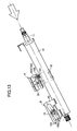
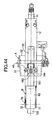
- FIGS. 15 to 19 show a third embodiment of the impact-absorbing steering column apparatus according to the present invention.
- collision-energy-absorbing means for absorbing secondary collision energy of the occupant H includes three energy-absorbing members 111, 112, and 113 provided in the upper support mechanism A; an engagement hook 114 provided on the steering column 12; and an energy-absorbing member 115 provided on the lower support mechanism B.
- Structural features other than the collision-energy-absorbing means for absorbing secondary collision energy of the occupant H are substantially identical with those of the above-described first embodiment and are thus denoted by common reference numerals, and repeated description thereof is omitted.
- the energy-absorbing members 111, 112, and 113 are iron bars and plastically deformed when the engagement hook 114 is engaged with them and moves frontward, thereby absorbing secondary collision energy.
- the energy-absorbing members 111, 112, and 113 are attached in array to the reinforcement plate 31 B of the support bracket 31 in the upper support mechanism A.
- Each of the energy-absorbing members 111, 112, and 113 is formed into a shape resembling the lying letter U that opens frontward and includes portions extending between its intermediate region and its front ends along the axial direction of the steering column 12. As shown in FIG. 17 , a rear end portion of each of the energy-absorbing members 111, 112, and 113 is curved downward and thus can be engaged with the engagement hook 114 substantially at its center.
- a cutout 31 d is formed in the reinforcement plate 31 B of the support bracket 31 in order to allow frontward movement of the engagement hook 114 engaged with the energy-absorbing member(s) 111 (112 and 113).
- the engagement hook 114 is provided on the steering column 12 in an upward projecting condition.
- the engagement hook 114 can engage with the energy-absorbing member(s) 111 (112 and 113). Being engaged with the energy-absorbing member(s) 111 (112 and 113), the engagement hook 114 can plastically deform the energy-absorbing member(s) 111 (112 and 113).
- the energy-absorbing member 115 provided in the lower support mechanism B is an elongated plate.
- the energy-absorbing member 115 is engaged with the collar 73 of the connection means 70 and plastically deformed to thereby absorb secondary collision energy.
- the energy-absorbing member 115 is fixedly attached, at its one end portion 105a, to the column-side bracket 62 in the lower support mechanism B; loops around the collar 73; and extends frontward.
- the steering column 12 moves frontward along its axial direction.
- the engagement hook 114 is engaged with none of the energy-absorbing members 111, 112, and 113, the energy-absorbing member 115 is plastically deformed by means of the collar 73.
- an absorption load for secondary collision energy is small.
- the engagement hook 114 is engaged with the bottom energy-absorbing member 111 to thereby plastically deform the energy-absorbing member 111, while the energy-absorbing member 115 is plastically deformed by means of the collar 73.
- an absorption load for secondary collision energy is larger than that in the case of FIG. 18 .
- energy-absorption-load-changing means including the energy-absorbing members 111, 112, and 113 and the engagement hook 114 changes an absorption load for secondary collision energy in accordance with the direction and load of a secondary collision of the occupant H with the steering system.
- the third embodiment can be mechanically implemented by means of appropriately setting, for example, the shape of the energy-absorbing members 111, 112, and 113 and the shape and arrangement of the engagement hook 114, without need to employ electrical control, whose cost is high, and thus at low cost.
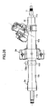
- FIGS. 20 to 24 show a fourth embodiment of the impact-absorbing steering column apparatus according to the present invention.
- collision-energy-absorbing means for absorbing secondary collision energy of the occupant H includes laterally paired energy-absorbing members 121 and 122, a cam 123, and an energy-absorbing member 124 provided on the lower support mechanism B.
- Structural features other than the collision-energy-absorbing means for absorbing secondary collision energy of the occupant H are substantially identical with those of the above-described first embodiment and are thus denoted by common reference numerals, and repeated description thereof is omitted.
- the laterally paired energy-absorbing members 121 and 122 are iron plates and plastically deformed when moving frontward while being engaged with the cam 123, thereby absorbing secondary collision energy.
- the laterally paired energy-absorbing members 121 and 122 are integrally formed with corresponding laterally paired vertical walls of the column-side bracket 62 in the lower support mechanism B and extend in the front-rear direction while being slightly inclined upward in relation to the axial direction of the steering column 12.
- the cam 123 is employed in place of the bushes 71, 72 and the collar 73 of the connection means 70.
- the cam 123 is nonrotatably attached to a square portion 74a of the bolt 74 at such an angle that one of four flat portions 123a formed on its outer surface in a diagonally facing condition is substantially aligned with the longitudinal direction of the laterally paired elongated holes 62a provided in the column-side bracket 62.
- the cam 123 is rotatable in relation to the elongated holes 62a.
- the cam 123 can be engaged with the energy-absorbing members 121, 122, and 124. Being engaged with the energy-absorbing members 121 and 122 and the energy-absorbing member 124, the cam 123 can plastically deform the energy-absorbing members 121, 122, and 124.
- the energy-absorbing member 124 is an elongated plate.
- the energy-absorbing member 124 is engaged with the cam 123 and plastically deformed to thereby absorb secondary collision energy.
- the energy-absorbing member 124 is fixedly attached, at its one end portion (not shown), to the column-side bracket 62; loops around the cam 123; and extends frontward (see FIG. 20 ).
- the steering column 12 moves frontward along its axial direction.
- the flat portions 123a of the cam 123 are engaged with the energy-absorbing members 121 and 122 (the energy-absorbing members 121 and 122 are hardly plastically deformed by means of the cam 123)
- the energy-absorbing member 124 is plastically deformed by means of the cam 123.
- corner portions of the cam 123 are engaged with the energy-absorbing members 121 and 122 to thereby plastically deform the energy-absorbing members 121 and 122, while the energy-absorbing member 124 is plastically deformed by means of the cam 123.
- an absorption load for secondary collision energy is larger than that in the case of FIG. 23 .
- energy-absorption-load-changing means including the energy-absorbing members 121, 122, and 124 and the cam 123 changes an absorption load for secondary collision energy in accordance with the direction and load of a secondary collision of the occupant H with the steering system.
- the fourth embodiment can be mechanically implemented by means of appropriately setting, for example, the shape and arrangement of the energy-absorbing members 121, 122, and 124 and the cam 123, without need to employ electrical control, whose cost is high, and thus at low cost.
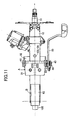
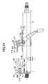
- FIGS. 25 to 31 show a fifth embodiment of the impact-absorbing steering column apparatus according to the present invention.
- the fifth embodiment employs a ball-type collision-energy-absorbing device as collision-energy-absorbing means for absorbing secondary collision energy of the occupant H.
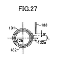
- the ball-type collision-energy-absorbing device includes a plurality of balls 131, a ring 132 for holding the balls 131, and a rod 133 capable of press-rotating the ring 132.
- the steering shaft 11 is composed of an upper shaft 11a and a lower shaft 11b.
- the upper shaft 11a and the lower shaft 11 b can axially extend and contract in relation to each other and can transmit torque.
- the steering column 12 is composed of an upper column 12a and a lower column 12b.
- the upper column 12a and the lower column 12b can axially extend and contract in relation to each other and support respectively the upper shaft 11 a and the lower shaft 11 b rotatably and in an axially immovable condition.
- the upper column 12a is supported at a predetermined tilt angle to a steering mounting member, which is a portion of a vehicle body, by means of the upper support mechanism Aa, in a tiltable condition and in such a condition as to be detachable frontward under a set load.
- the lower column 12b is supported at a predetermined tilt angle to the steering mounting member, which is a portion of the vehicle body, by means of the lower support mechanism Ba, in a tiltable (pivotable) condition.
- Three engagement grooves 12b1, 12b2, and 12b3 are axially formed for each of the balls 131 on the outer circumferential surface of the lower column 12b.
- the engagement grooves 12b1, 12b2, and 12b3 differ in depth and are formed on the lower column 12b in a circumferentially arranged condition. Initially, the balls 131 are engaged with the corresponding engagement grooves 12b1.
- the engagement grooves 12b1 are the deepest; the engagement grooves 12b2 are the next deepest; and the engagement grooves 12b3 are the shallowest.
- the balls 131 are of steel and held within the ring 132 at predetermined circumferential intervals.
- the balls 131 and the ring 132 are rotatable and axially movable in a unitary condition. When the balls 131, together with the ring 132, move frontward in the axial direction, the balls 131 can plastically deform the outer circumference of the lower column 12b along the engagement grooves 12b1, 12b2, or 12b3.
- the ring 132 has a plurality of spherical holes 132b (see FIG. 31 ) formed along its inner circumference.
- the spherical holes 132b are adapted to partially accommodate the corresponding balls 131.
- the ring 132 is attached to the outer circumference of the lower column 12b via the balls 131.
- An arm 132a is provided on the right-hand side of the ring 132 and projects radially outward. The arm 132a can be engaged with the rod 133.
- the rod 133 is fixedly attached to the steering mounting member and projects downward. As shown in FIG. 28 , when the lower column 12b of the steering column 12 tilts upward by a predetermined amount ⁇ beyond a tilt stroke L, the rod 133 is engaged with the arm 132a to thereby rotate the ring 132 clockwise in FIG. 28 .
- the upper column 12a of the steering column 12 in the event of a secondary collision that accompanies a collision of the vehicle; for example, when, as shown in FIG. 29 , a secondary collision load is input to the upper column 12a of the steering column 12 in the direction of the arrow (in the direction of the column axis) via the upper shaft 11a of the steering shaft 11, the upper column 12a moves frontward along its axial direction and pushes the ring 132 frontward.
- the balls 131 together with the ring 132, move frontward while being engaged with the corresponding deepest engagement grooves 12b1, thereby plastically deforming the outer circumference of the lower column 12b along the engagement grooves 12b1. Since secondary collision energy is absorbed by means of slight plastic deformation of the outer circumference of the lower column 12b caused by the balls 131, an absorption load for secondary collision energy is small.
- the outer circumference of the lower column 12b is plastically deformed by means of the balls 131 to a greater extent than in the case where the ring 132 is not rotated, whereby secondary collision energy is absorbed.
- an absorption load for secondary collision energy is larger than that in the case where the ring 132 is not rotated.
- energy-absorption-load-changing means including the rod 133, the ring 132, and the balls 131 changes an absorption load for secondary collision energy in accordance with the direction and load of a secondary collision of the occupant H with the steering system.
- the fifth embodiment can be mechanically implemented by means of appropriately setting, for example, the shape and arrangement of the rod 133, the ring 132, the balls 131, and the engagement grooves 12b1 to 12b3, without need to employ electrical control, whose cost is high, and thus at low cost.
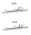
- FIGS. 32 to 36 show a sixth embodiment of the impact-absorbing steering column apparatus according to the present invention.
- collision-energy-absorbing means for absorbing secondary collision energy of the occupant H includes an energy-absorbing member 141 provided in the upper support mechanism A and an energy-absorbing member 143 provided in the lower support mechanism B.
- Structural features other than the collision-energy-absorbing means for absorbing secondary collision energy of the occupant H are substantially identical with those of the above-described first embodiment and are thus denoted by common reference numerals, and repeated description thereof is omitted.
- the energy-absorbing member 141 is an iron plate and plastically deformed when moving frontward while being engaged with the reinforcement plate 31 B of the support bracket 31 in the upper support mechanism A, thereby absorbing secondary collision energy.
- the energy-absorbing member 141 together with a base plate 142 formed of an iron plate, is welded to the upper surface of the steering column 12.
- the energy-absorbing member 141 includes a bulge portion 141 a bulging upward and extending from its intermediate portion to its rear end portion.
- the bulge portion 141a extends along the axial direction of the steering column 12 and can be engaged with a curved lower end portion of the reinforcement plate 31 B, which is bent to have an L-shaped cross section.
- the energy-absorbing member 143 provided in the lower support mechanism B is an elongated plate.
- the energy-absorbing member 143 is engaged with the collar 73 of the connection means 70 and plastically deformed to thereby absorb secondary collision energy.
- the energy-absorbing member 143 is fixedly attached, at its one end portion, to the column-side bracket 62 in the lower support mechanism B; loops around the collar 73; and extends frontward.
- the steering column 12 tilts upward at the initial stage of the secondary collision and subsequently moves frontward along its axial direction.
- the bulge portion 141 a of the upper energy-absorbing member 141 is engaged with the curved lower end portion of the reinforcement plate 31B of the support bracket 31 and moves frontward.
- the upper energy-absorbing member 141 may not be plastically deformed.
- the lower energy-absorbing member 143 is plastically deformed by means of the collar 73. Since secondary collision energy is absorbed by means of plastic deformation of only the energy-absorbing member 143 caused by the collar 73, an absorption load for secondary collision energy is small.
- the bulge portion 141 a of the upper energy-absorbing member 141 may be engaged with the curved lower end portion of the reinforcement plate 31 B of the support bracket 31.
- the energy-absorbing member 141 moves frontward while being plastically deformed. Since secondary collision energy is absorbed by means of plastic deformation of the energy-absorbing member 141 caused by the reinforcement plate 31B and plastic deformation of the energy-absorbing member 143 caused by the collar 73, an absorption load for secondary collision energy is larger than that in the case where the upward component of load is small. In this case, the quantity of plastic deformation of the energy-absorbing member 141 caused by the reinforcement member 31 B varies dependently on the upward component of the secondary collision load input to the steering column 12.
- energy-absorption-load-changing means including the energy-absorbing member 141 and the reinforcement plate 31B changes an absorption load for secondary collision energy in accordance with the direction and load of a secondary collision of the occupant H with the steering system.
- the sixth embodiment can be mechanically implemented by means of appropriately setting, for example, the shape of the bulge portion 141 a of the energy-absorbing member 141 and the shape and arrangement of the reinforcement plate 31 B, without need to employ electrical control, whose cost is high, and thus at low cost.
- FIGS. 37 to 42 show a seventh embodiment of the impact-absorbing steering column apparatus according to the present invention.
- collision-energy-absorbing means for absorbing secondary collision energy of the occupant H includes an energy-absorbing member 151 provided in the upper support mechanism A and an energy-absorbing member 153 provided in the lower support mechanism B.
- Structural features other than the collision-energy-absorbing means for absorbing secondary collision energy of the occupant H are substantially identical with those of the above-described first embodiment and are thus denoted by common reference numerals, and repeated description thereof is omitted.
- the energy-absorbing member 151 is an iron plate and plastically deformed when moving frontward while being engaged with the reinforcement plate 31 B of the support bracket 31 in the upper support mechanism A, thereby absorbing secondary collision energy.
- the energy-absorbing member 151 together with a base plate 152, is welded to the upper surface of the steering column 12.
- the energy-absorbing member 151 assumes an arcuate cross-sectional shape so as to be curved similarly to the outer circumference of the steering column 12 with a predetermined gap held therebetween.
- An upper surface of the energy-absorbing member 151 extending from its intermediate portion to its rear end portion can be engaged with a curved lower end portion of the reinforcement plate 31 B, which is bent to have an L-shaped cross section.
- the base plate 152 is an iron plate and adapted to form a space (a space that enables plastic deformation of the energy-absorbing member 151) between the steering column 12 and the energy-absorbing member 151.
- the base plate 152 assumes an arcuate cross-sectional shape so as to be curved similarly to the outer circumference of the steering column 12.
- the base plate 152 has a cutout that assumes a rectangular shape as viewed in plane. The cutout is formed in a region extending from an intermediate portion of the base plate 152 to a rear end portion of the base plate 152.
- the energy-absorbing member 153 provided in the lower support mechanism B is an elongated plate.
- the energy-absorbing member 153 is engaged with the collar 73 of the connection means 70 and plastically deformed to thereby absorb secondary collision energy.
- the energy-absorbing member 153 is fixedly attached, at its one end portion, to the column-side bracket 62 in the lower support mechanism B; loops around the collar 73; and extends frontward.
- the steering column 12 tilts upward at the initial stage of the secondary collision and subsequently moves frontward along its axial direction.
- the upper energy-absorbing member 151 is engaged with the curved lower end portion of the reinforcement plate 31 B of the support bracket 31 and moves frontward.
- the upper energy-absorbing member 151 may not be plastically deformed.
- the lower energy-absorbing member 153 is plastically deformed by means of the collar 73. Since secondary collision energy is absorbed by means of plastic deformation of only the energy-absorbing member 153 caused by the collar 73, an absorption load for secondary collision energy is small.
- energy-absorption-load-changing means including the energy-absorbing member 151 and the reinforcement plate 31 B changes an absorption load for secondary collision energy in accordance with the direction and load of a secondary collision of the occupant H with the steering system.
- the seventh embodiment can be mechanically implemented by means of appropriately setting, for example, the shape of the energy-absorbing member 151, the shape of the base plate 152, and the shape and arrangement of the reinforcement plate 31 B, without need to employ electrical control, whose cost is high, and thus at low cost.
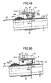
- FIGS. 43 to 50 show an eighth embodiment of the impact-absorbing steering column apparatus according to the present invention.
- collision-energy-absorbing means for absorbing secondary collision energy of the occupant H includes an energy-absorbing member 161 provided in the upper support mechanism A, a deformable portion 31 e provided in the plate 31A of the support bracket 31 in the upper support mechanism A, and an energy-absorbing member 165 provided in the lower support mechanism B.
- Structural features other than the collision-energy-absorbing means for absorbing secondary collision energy of the occupant H are substantially identical with those of the above-described first embodiment and are thus denoted by common reference numerals, and repeated description thereof is omitted.
- the energy-absorbing member 161 is a thin iron plate and squeeze-deformed when the steering column 12 moves frontward with the energy-absorbing member 161 being engaged with the reinforcement plate 31 B of the support bracket 31 in the upper support mechanism A, thereby absorbing secondary collision energy.
- the energy-absorbing member 161 is provided on the upper surface of the steering column 12 in such a manner as to be movable in the direction of the column axis, by use of a guide plate 162, a holder 163, and a round bar 164.
- the energy-absorbing member 161 has a projection 161 a projecting upward from its rear end portion. The projection 161a can be engaged with an engagement hole 31 formed in the reinforcement palate 31 B.
- the guide plate 162 is an iron plate and allows the energy-absorbing member 161 to move along the steering column 12 when the energy-absorbing member 161 is squeeze-deformed.
- the guide plate 162 is welded to the upper surface of the steering column 12.
- the holder 163 is an iron plate and causes squeeze-deformation of the energy-absorbing member 161 in cooperation with the round bar 164.
- the holder 163 is welded to an upper portion of the steering column 12 while straddling a portion of the energy-absorbing member 161 and a portion of the guide plate 162.
- the round bar 164 is made of iron and is incorporated in the holder 163 together with a portion of the energy-absorbing member 161.
- the deformable portion 31 e provided on the plate 31 A of the support bracket 31 in the upper support mechanism A is formed by means of forming in the plate 31A an elongated hole 31e1 extending in the front-rear direction.
- the deformable portion 31 e is plastically deformed upward, thereby allowing the projection 161 a of the energy-absorbing member 161 to be fitted into the engagement hole 31 f formed in the reinforcement plate 31 B.
- the energy-absorbing member 165 provided in the lower support mechanism B is an elongated plate.
- the energy-absorbing member 165 is engaged with the collar 73 of the connection means 70 and plastically deformed to thereby absorb secondary collision energy.
- the energy-absorbing member 165 is fixedly attached, at its one end portion, to the column-side bracket 62 in the lower support mechanism B; loops around the collar 73; and extends frontward.
- the steering column 12 tilts upward at the initial stage of the secondary collision and subsequently moves frontward along its axial direction.
- an upward component of the secondary collision load input to the steering column 12 is small, as shown in FIGS. 47 and 48 , the deformable portion 31e provided on the plate 31A of the support bracket 31 in the upper support mechanism A is not plastically deformed.
- the deformable portion 31e provided on the plate 31A of the support bracket 31 receives an upward load equal to or greater than a set value from the collar 42 and the lock bolt 41 of the clamp means 40 to thereby be plastically deformed upward.
- the projection 161a of the energy-absorbing member 161 is fitted into the engagement hole 31f formed in the reinforcement plate 31 B.
- the holder 163 and the round bar 164 squeeze-deforms the energy-absorbing member 161.
- the lower energy-absorbing member 165 is plastically deformed by means of the collar 73.
- energy-absorption-load-changing means including the energy-absorbing member 161, the guide plate 162, the holder 163, the round bar 164, and the support bracket 31 in the upper support mechanism A changes an absorption load for secondary collision energy in accordance with the direction and load of a secondary collision of the occupant H with the steering system.
- the eighth embodiment can be mechanically implemented by means of appropriately setting, for example, the shape of the projection 161a of the energy-absorbing member 161, the shape of the holder 163, the shape of the round bar 164, and the shape and arrangement of the support bracket 31 in the upper support mechanism A, without need to employ electrical control, whose cost is high, and thus at low cost.
- FIGS. 51 to 58 show a ninth embodiment of the impact-absorbing steering column apparatus according to the present invention.
- collision-energy-absorbing means for absorbing secondary collision energy of the occupant H includes an energy-absorbing member 171 provided in the upper support mechanism A, the deformable portion 31 e provided in the plate 31 A of the support bracket 31 in the upper support mechanism A, and an energy-absorbing member 173 provided in the lower support mechanism B.
- Structural features other than the collision-energy-absorbing means for absorbing secondary collision energy of the occupant H are substantially identical with those of the above-described first embodiment and are thus denoted by common reference numerals, and repeated description thereof is omitted.
- the energy-absorbing member 171 is a thin iron plate and plastically deformed when moving frontward while being engaged with the reinforcement plate 31 B of the support bracket 31 in the upper support mechanism A, thereby absorbing secondary collision energy.
- the energy-absorbing member 171, together with a base plate 172, is welded to the upper surface of the steering column 12.
- the energy-absorbing member 171 includes a bulge portion 171 a bulging upward and extending from its intermediate portion to its rear end portion.
- the bulge portion 171a extends along the axial direction of the steering column 12 and can be engaged with a curved lower end portion of the reinforcement plate 31 B, which is bent to have an L-shaped cross section.
- the deformable portion 31 e provided on the plate 31A of the support bracket 31 in the upper support mechanism A is formed by means of forming in the plate 31A the elongated hole 31e1 extending in the front-rear direction.
- the deformable portion 31 e receives an upward load equal to or greater than a set value from the collar 42 and the lock bolt 41 of the clamp means 40, the deformable portion 31e is plastically deformed upward, thereby allowing the bulge portion 171a of the energy-absorbing member 171 to be engaged with the curved lower end portion of the reinforcement plate 31B.
- the energy-absorbing member 173 provided in the lower support mechanism B is an elongated plate.
- the energy-absorbing member 173 is engaged with the collar 73 of the connection means 70 and plastically deformed to thereby absorb secondary collision energy.
- the energy-absorbing member 173 is fixedly attached, at its one end portion, to the column-side bracket 62 in the lower support mechanism B; loops around the collar 73; and extends frontward.
- the steering column 12 tilts upward at the initial stage of the secondary collision and subsequently moves frontward along its axial direction.
- the deformable portion 31 e provided on the plate 31 A of the support bracket 31 in the upper support mechanism A is not plastically deformed; and the bulge portion 171 a of the upper energy-absorbing member 171 is engaged with the curved lower end portion of the reinforcement plate 31 B of the support bracket 31, but is not plastically deformed.
- the lower energy-absorbing member 173 is plastically deformed by means of the collar 73. Since secondary collision energy is absorbed by means of plastic deformation of only the energy-absorbing member 173 caused by the collar 73, an absorption load for secondary collision energy is small.
- the deformable portion 31 e provided on the plate 31A of the support bracket 31 receives an upward load equal to or greater than a set value from the collar 42 and the lock bolt 41 of the clamp means 40 to thereby be plastically deformed upward.
- the bulge portion 171a of the upper energy-absorbing member 171 is engaged with the curved lower end portion of the reinforcement plate 31 B of the support bracket 31.
- the bulge portion 171 a of the upper energy-absorbing member 171 is plastically deformed by means of the reinforcement plate 31 B of the support bracket 31.
- the lower energy-absorbing member 173 is plastically deformed by means of the collar 73.
- energy-absorption-load-changing means including the energy-absorbing member 171 and the support bracket 31 in the upper support mechanism A changes an absorption load for secondary collision energy in accordance with the direction and load of a secondary collision of the occupant H with the steering system.
- the ninth embodiment can be mechanically implemented by means of appropriately setting, for example, the shape of the bulge portion 171 a of the energy-absorbing member 171 and the shape and arrangement of the support bracket 31 in the upper support mechanism A, without need to employ electrical control, whose cost is high, and thus at low cost.
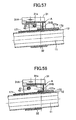
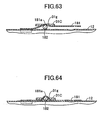
- FIGS. 59 to 64 show a tenth embodiment of the impact-absorbing steering column apparatus according to the present invention.
- collision-energy-absorbing means for absorbing secondary collision energy of the occupant H includes an energy-absorbing member 181 provided in the upper support mechanism A, squeezing plate 31C provided on the reinforcement plate 31B of the support bracket 31 in the upper support mechanism A, and an energy-absorbing member 183 provided in the lower support mechanism B.
- Structural features other than the collision-energy-absorbing means for absorbing secondary collision energy of the occupant H are substantially identical with those of the above-described first embodiment and are thus denoted by common reference numerals, and repeated description thereof is omitted.
- the energy-absorbing member 181 is a thin iron plate and squeeze-deformed when the steering column 12 moves frontward with the energy-absorbing member 181 being engaged with the squeezing plate 31C provided on the reinforcement plate 31B of the support bracket 31 in the upper support mechanism A, thereby absorbing secondary collision energy.
- the energy-absorbing member 181 is welded, at its front end portion, to the upper surface of the steering column 12.
- the energy-absorbing member 181 includes a curved portion 181 a located in its axially intermediate region, curved upward, and adapted to accommodate a round bar 182, and laterally paired arm portions 181b for restricting lateral movement of the round bar 182.
- the curved portion 181a which accommodates the round bar 182, can be engaged with an engagement hole 31g formed in the squeezing plate 31C by means of being fitted into the engagement hole 31g.
- the squeezing plate 31C provided on the reinforcement plate 31B of the support bracket 31 in the upper support mechanism A is an iron plate and causes squeeze-deformation of the energy-absorbing member 181 in cooperation with the round bar 182.
- the squeezing plate 31C is welded to the lower surface of the reinforcement plate 31B.
- the round bar 182 is a solid iron rod; is incorporated in the curved portion 181 a of the energy-absorbing member 181; and is movable along the upper surface of the steering column 12 in the direction of the column axis.
- the energy-absorbing member 183 provided in the lower support mechanism B is an elongated plate.
- the energy-absorbing member 183 is engaged with the collar 73 of the connection means 70 and plastically deformed to thereby absorb secondary collision energy.
- the energy-absorbing member 183 is fixedly attached, at its one end portion, to the column-side bracket 62 in the lower support mechanism B; loops around the collar 73; and extends frontward.
- the steering column 12 tilts upward at the initial stage of the secondary collision and subsequently moves frontward along its axial direction.
- an upward component of the secondary collision load input to the steering column 12 is small, as shown in FIG.
- energy-absorption-load-changing means including the energy-absorbing member 181, the round bar 182, and the squeezing plate 31C provided on the reinforcement plate 31B of the support bracket 31 in the upper support mechanism A changes an absorption load for secondary collision energy in accordance with the direction and load of a secondary collision of the occupant H with the steering system.
- the tenth embodiment can be mechanically implemented by means of appropriately setting, for example, the shape of the energy-absorbing member 181, the shape of the round bar 182, and the shape and arrangement of the squeezing plate 31C provided on the reinforcement plate 31 B of the support bracket 31 in the upper support mechanism A, without need to employ electrical control, whose cost is high, and thus at low cost.
Description
- The present invention relates to an impact-absorbing steering column apparatus according to the preamble of
claim 1 of the invention having collision-energy-absorbing means for absorbing secondary collision energy of an occupant (driver) in the event of a collision of a vehicle.EP 0 655 383 discloses such a steering column, including the features of the preamble ofclaim 1. - A conventional impact-absorbing steering column apparatus effects absorption of secondary collision energy such that column drive means causes a steering column to retreat in relation to an occupant in accordance with the distance between the occupant and a steering wheel or the position of the steering column in relation to the occupant or such that energy absorption quantity adjustment means varies, in accordance with the distance or the position, the quantity of secondary impact energy to be absorbed by collision-energy-absorbing means. Such an impact-absorbing steering column apparatus is disclosed in, for example, Japanese Patent Application Laid-Open (kokai) No.
2002-79944 - The above-mentioned conventional impact-absorbing steering column apparatus is configured such that the column drive means and the energy absorption quantity adjustment means are operated under the control of an electrical control unit. The distance between the occupant and the steering wheel or the position of the steering column in relation to the occupant is electrically detected. On the basis of the detected distance or position, at least either the column drive means or the energy absorption quantity adjustment means is electrically controlled. Thus, a problem of high cost is involved.
-
US-B1-6 322 103 describes an actively variable energy absorber for a steering column, which counteracts a linear translation of a steering column housing in the direction of the centerline of the steering column due to a collision of a driver with a steering wheel. Thereby, the driver is decelerated by converting the kinetic energy of his motion into deformation energy of a flat metal strap being bent by means of a counterpart. - The present invention has been accomplished in order to solve the above problem, and an object of the invention is to change an absorption load for secondary collision energy of an occupant in the event of a secondary collision of the occupant with a steering system, by means of a mechanical action effected by the secondary collision. This objet is achieved by an impact-absorbing steering column apparatus with the features of
claim 1 of the invention. - An aspect of the present invention provides an impact-absorbing steering column apparatus comprising collision-energy-absorbing means for absorbing secondary collision energy of an occupant in the event of a collision of a vehicle. The collision-energy-absorbing means comprises energy-absorption-load-changing means for changing an absorption load for the secondary collision energy. The energy-absorption-load-changing means is adapted to change the absorption load in accordance with displacement of a steering column, the displacement changing dependently on a secondary collision of the occupant with a steering system.
- According to the present invention, for example, in the event of a collision of the vehicle, the occupant moves in a certain direction toward the front of the vehicle while having certain kinetic energy, depending on whether or not the occupant wears a seat belt, a collision speed, a seat position, and like factors; and a certain secondary collision load is input to the steering system along a certain direction of a secondary collision.
- Thus, the energy-absorption-load-changing means of the collision-energy-absorbing means can change the absorption load for secondary collision in accordance with displacement of the steering column, the displacement changing dependently on a secondary collision of the occupant with the steering system. In other words, in accordance with the direction of the secondary collision of the occupant with the steering system and/or the magnitude of the collision load, the steering column is displaced or allowed to be readily displaced in a direction different from a direction along which the steering column moves in relation to the vehicle body toward the front of the vehicle while absorbing energy. By means of association of displacement of the steering column with an action of the energy-absorption-load-changing means, an absorption load to be generated by the energy-absorption-load-changing means can be changed in accordance with the displacement of the steering column.
- Another aspect of the present invention provides an impact-absorbing steering column apparatus comprising collision-energy-absorbing means for absorbing secondary collision energy of an occupant in the event of a collision of a vehicle. The collision-energy-absorbing means comprises energy-absorption-load-changing means for changing an absorption load for the secondary collision energy. The energy-absorption-load-changing means is adapted to change the absorption load in accordance with displacement of the steering column in a direction intersecting a direction of relative movement of the steering column for absorbing collision energy induced by a secondary collision of the occupant.
- According to the present invention, for example, in the event of a collision of the vehicle, the occupant moves in a certain direction toward the front of the vehicle while having certain kinetic energy, depending on whether or not the occupant wears a seat belt, a collision speed, a seat position, and like factors; and a certain secondary collision load is input to the steering system along a certain direction of a secondary collision.
- Thus, by utilizing displacement of the steering column in a direction intersecting a direction along which the steering column moves in relation to the vehicle body toward the front of the vehicle while absorbing collision energy, the energy-absorption-load-changing means adapted to absorb energy can change an absorption load. In other words, in accordance with the direction of the secondary collision of the occupant with the steering system and/or the magnitude of the collision load, the steering column is displaced or allowed to be readily displaced in a direction different from a direction along which the steering column moves in relation to the vehicle body toward the front of the vehicle while absorbing energy. By means of association of displacement of the steering column with an action of the energy-absorption-load-changing means, an absorption load to be generated by the energy-absorption-load-changing means can be changed in accordance with the displacement of the steering column.
- According to a further aspect of the present invention, the energy-absorption-load-changing means changes the absorption load in accordance with a mode of displacement of the steering column. According to the present invention, for example, an absorption load to be generated by the energy-absorption-load-changing means is changed in accordance with a mode of displacement of the steering column, so that the absorption load can be changed in accordance with the displaced position of the steering column.
- According to a further aspect of the present invention, the energy-absorption-load-changing means comprises an energy-absorbing member, and engagement means capable of engaging with the energy-absorbing member, and an engagement relation between the energy-absorbing member and the engagement means varies in accordance with a mode of displacement of the steering column, thereby changing the absorption load. According to the present invention, for example, the engagement relation between the energy-absorbing member and the engagement means can be varied in accordance with a mode of displacement of the steering column, whereby the absorption load can be changed.
- According to a further aspect of the present invention, the engagement means is squeezing means for squeezing the energy-absorbing member; the energy-absorbing member has an energy-absorbing portion, which is squeezed by the squeezing means to thereby absorb energy; and an engagement relation between the squeezing means and the energy-absorbing portion varies in accordance with a mode of displacement of the steering column, thereby changing the absorption load. According to the present invention, for example, the engagement relation between the squeezing means and the energy-absorbing portion is varied in accordance with a mode of displacement of the steering column, whereby the absorption load can be changed.
- According to a further aspect of the present invention, the engagement means is squeezing means for squeezing the energy-absorbing member; the energy-absorbing member has a plurality of energy-absorbing portions that differ in energy absorption load in relation to the squeezing means; and an engagement between the squeezing means and one of the plurality of energy-absorbing portions is selected in accordance with a mode of displacement of the steering column, thereby changing the absorption load. According to the present invention, for example, an engagement between the squeezing means and one of the plurality of energy-absorbing portions is selected in accordance with a mode of displacement of the steering column, whereby the absorption load can be changed.
- According to a further aspect of the present invention, the engagement means is squeezing means for squeezing the energy-absorbing member; the squeezing means has a plurality of squeezing portions that differ in the quantity of draw/squeeze in squeezing the energy-absorbing member; and an engagement between the energy-absorbing member and one of the plurality of squeezing portions is selected in accordance with a mode of displacement of the steering column, thereby changing the absorption load. According to the present invention, for example, an engagement between the squeezing means and one of the plurality of squeezing portions is selected in accordance with a mode of displacement of the steering column, whereby the absorption load can be changed.
- According to a further aspect of the present invention, the energy-absorbing member is a linear member capable of engaging with the engagement means; the engagement means is engaged with or is not engaged with the linear member in accordance with a mode of displacement of the steering column, thereby changing the absorption load. According to the present invention, for example, the engagement means is engaged with or is not engaged with the linear member in accordance with a mode of displacement of the steering column, whereby the absorption load can be changed.
- According to a further aspect of the present invention, the energy-absorbing member is a plurality of linear members capable of engaging with the engagement means; the number of the linear members to be engaged with the engagement means varies in accordance with a mode of displacement of the steering column, thereby changing the absorption load. According to the present invention, for example, the number of the linear members to be engaged with the engagement means varies in accordance with a mode of displacement of the steering column, whereby the absorption load can be changed.
- According to a further aspect of the present invention, the steering column comprises the energy-absorbing member, a ball adapted to plastically deform the energy-absorbing member, and ball support means for adjusting the quantity of plastic deformation to be effected by the ball; and the ball support means is moved in accordance with a mode of displacement of the steering column in such a manner as to vary an engagement relation between the energy-absorbing member and the ball in accordance with the mode, thereby changing the absorption load. According to the present invention, for example, the ball support means is moved in such a manner as to vary the engagement relation between the energy-absorbing member and the ball in accordance with a mode of displacement of the steering column, whereby the absorption load can be changed.
- According to a further aspect of the present invention, the energy-absorbing member has an elongated groove having a predetermined width; the engagement means is squeezing means assuming a special shape and capable of being displaced in the elongated groove in relation to the energy-absorbing member; and an engagement relation between the special-shape squeezing means and the elongated groove of the energy-absorbing member varies in accordance with a mode of displacement of the steering column, thereby changing the absorption load. According to the present invention, for example, the engagement relation between the special-shape squeezing means and the elongated groove of the energy-absorbing member varies in accordance with a mode of displacement of the steering column, whereby the absorption load can be changed.
- According to a further aspect of the present invention, an energy-absorbing member is provided on either a vehicle-body-side member or the steering column, the energy-absorbing member generating an energy absorption load by means of displacement in relation to either the vehicle-body-side member or the steering column on which the energy-absorbing member is provided; the engagement means capable of engaging with the energy-absorbing member is provided on either the vehicle-body-side member or the steering column on which the energy-absorbing member is not provided; and when the energy-absorbing member is engaged with the engagement means in accordance with a mode of displacement of the steering column, the mode changing dependently on a secondary collision, the energy-absorbing member incrementally changes the absorption load by means of displacement in relation to either the vehicle-body-side member or the steering column on which the energy-absorbing member is provided. According to the present invention, for example, when the energy-absorbing member is engaged with the engagement means in accordance with a mode of displacement of the steering column, the mode of displacement changing dependently on a secondary collision, the energy-absorbing member can incrementally change the absorption load by means of displacement in relation to either the vehicle-body-side member or the steering column on which the energy-absorbing member is provided.
- According to a further aspect of the present invention, the energy-absorption-load-changing means changes the absorption load in accordance with displacement of the steering column, the displacement changing dependently on the direction of a secondary collision of the occupant with the steering system. According to the present invention, for example, the energy-absorption-load-changing means can change the absorption load in accordance with displacement of the steering column, the displacement changing dependently on the direction of a secondary collision of the occupant with the steering system.
- According to a further aspect of the present invention, the energy-absorption-load-changing means changes the absorption load in accordance with displacement of the steering column, the displacement changing dependently on the direction of a secondary collision of the occupant with the steering system at an initial stage of the secondary collision. According to the present invention, for example, the energy-absorption-load-changing means can change the absorption load in accordance with displacement of the steering column, the displacement changing dependently on the direction of a secondary collision of the occupant with the steering system at an initial stage of the secondary collision.
- According to a further aspect of the present invention, when a collision load associated with a secondary collision of the occupant with the steering system is equal to or greater than a predetermined value, the energy-absorption-load-changing means increases the absorption load. According to the present invention, for example, when a collision load associated with a secondary collision of the occupant with the steering system is equal to or greater than a predetermined value, the energy-absorption-load-changing means can increase the absorption load.
- According to a further aspect of the present invention, the energy-absorption-load-changing means increases the absorption load in accordance with such displacement that the steering column tilts upward as a result of a secondary collision of the occupant with the steering system. According to the present invention, for example, the energy-absorption-load-changing means can increase the absorption load in accordance with such displacement that the steering column tilts upward as a result of a secondary collision of the occupant with the steering system.
- According to a further aspect of the present invention, the energy-absorption-load-changing means changes the absorption load in accordance with a direction of displacement of the steering column, the direction of displacement changing dependently on the direction of a secondary collision of the occupant with the steering system. According to the present invention, for example, the energy-absorption-load-changing means can increase the absorption load in accordance with the displaced position of the steering column, the displaced position changing dependently on the direction of a secondary collision of the occupant with the steering system.
- According to a further aspect of the present invention, impact-absorbing means for absorbing a predetermined collision load is provided separately from the collision-energy-absorbing means. According to the present invention, for example, the impact-absorbing means for absorbing a predetermined collision load can be provided separately from the collision-energy-absorbing means.
- According to a further aspect of the present invention, the collision-energy-absorbing means selectively provides the absorption load, or changes the magnitude of the absorption load. According to the present invention, for example, the collision-energy-absorbing means can determine whether to effect the absorption load or can change the magnitude of the absorption load.
- According to a further aspect of the present invention, in accordance with a load of pressing the steering column against a vehicle-body-side member and a load of moving the steering column toward the front of the vehicle, the loads changing dependently on a secondary collision of the occupant with the steering system, deformation of an energy-absorbing member provided on either the steering column or the vehicle-body-side member is passively changed by engagement means provided on either the steering column or the vehicle-body-side member on which the energy-absorbing member is not provided, whereby the energy-absorption-load-changing means changes the absorption load. According to the present invention, for example, in accordance with a load of pressing the steering column against the vehicle-body-side member and a load of moving the steering column toward the front of the vehicle, the loads changing dependently on a secondary collision of the occupant with the steering system, deformation of the energy-absorbing member provided on either the steering column or the vehicle-body-side member is passively changed by the engagement means provided on either the steering column or the vehicle-body-side member on which the energy-absorbing member is not provided, whereby the absorption load can be changed.
- According to a further aspect of the present invention, the engagement means is formed on the vehicle-body-side member; the energy-absorbing member is provided on the steering column in opposition to the engagement means and assumes an elongated shape extending along an axis of the steering column; and the engagement means provided on the vehicle-body-side member causes the deformation of the energy-absorbing member provided on the steering column. According to the present invention, for example, the engagement means is formed on the vehicle-body-side member; the energy-absorbing member is provided on the steering column in opposition to the engagement means and assumes an elongated shape extending along the axis of the steering column; and the engagement means provided on the vehicle-body-side member can cause the deformation of the energy-absorbing member provided on the steering column.
- According to a further aspect of the present invention, only when a collision load imposed on the vehicle-body-side member from the steering column is equal to or greater than a predetermined value, abutment between the engagement means and the energy-absorbing member is enabled. According to the present invention, for example, only when a collision load imposed on the vehicle-body-side member from the steering column is equal to or greater than a predetermined value, the engagement means can abut the energy-absorbing member.
- According to a further aspect of the present invention, in the event of a secondary collision, the steering column is allowed to be displaced in such a manner as to tilt toward the vehicle-body-side member. According to the present invention, for example, in the event of a secondary collision, the steering column can be displaced in such a manner as to tilt toward the vehicle-body-side member.
- According to a further aspect of the present invention, the absorption load is increased with a load of pressing the steering column against the vehicle-body-side member. According to the present invention, for example, the absorption load can be increased with the load of pressing the steering column against the vehicle-body-side member.
- According to a further aspect of the present invention, impact-absorbing means for absorbing a predetermined collision load is provided separately from the collision-energy-absorbing means. According to the present invention, for example, the impact-absorbing means for absorbing a predetermined collision load can be provided separately from the collision-energy-absorbing means.
-
-
FIG. 1 is a side view showing a first embodiment of an impact-absorbing steering column apparatus according to the present invention; -
FIG. 2 is an enlarged side view showing essential portions ofFIG. 1 ; -
FIG. 3 is an enlarged sectional view taken along line 3-3 ofFIG. 2 ; -
FIG. 4 is an enlarged plan view of a steering mounting member shown inFIGS. 1 to 3 ; -
FIG. 5 is an enlarged side view partially showing a steering column, an upper support mechanism, and a lower support mechanism shown inFIGS. 1 and2 ; -
FIG. 6 is a vertical, longitudinal sectional view showing the configurational relation among a support bracket, energy-absorbing members, a bush, a collar, and a bolt, among others shown inFIG. 3 ; -
FIG. 7 is an explanatory view for explaining the action of essential portions when the steering column moves frontward in the event of a collision of the vehicle in the case of an occupant wearing a seat belt; -
FIG. 8 is an explanatory view for explaining the action of essential portions when the steering column moves frontward in the event of a collision of the vehicle in the case of the occupant not wearing the seat belt; -
FIG. 9 is a side view showing essential portions of a modification of the first embodiment; -
FIG. 10 is a side view showing a second embodiment of the impact-absorbing steering column apparatus according to the present invention; -
FIG. 11 is a plan view of the steering column assembly shown inFIG. 10 ; -
FIG. 12 is a vertical, transverse sectional view showing the configurational relation between energy-absorbing members and engagement pins shown inFIG. 10 ; -
FIG. 13 is an explanatory view for explaining an action in the event of input of a secondary collision load in the direction of the column axis into the steering column assembly shown inFIG. 10 ; -
FIG. 14 is an explanatory view for explaining an action in the event of input of a secondary collision load substantially in the horizontal direction into the steering column assembly shown inFIG. 10 ; -
FIG. 15 is a side view showing a third embodiment of the impact-absorbing steering column apparatus according to the present invention; -
FIG. 16 is a plan view of the steering column assembly shown inFIG. 15 ; -
FIG. 17 is a vertical, transverse sectional view showing the configurational relation between energy-absorbing members and an engagement hook shown inFIG. 15 ; -
FIG. 18 is an explanatory view for explaining an action in the event of input of a secondary collision load in the direction of the column axis into the steering column assembly shown in shown inFIG. 15 ; -
FIG. 19 is an explanatory view for explaining an action in the event of input of a secondary collision load substantially in the horizontal direction into the steering column assembly shown inFIG. 15 ; -
FIG. 20 is a side view showing a fourth embodiment of the impact-absorbing steering column apparatus according to the present invention; -
FIG. 21 is a plan view of the steering column assembly shown inFIG. 20 ; -
FIG. 22 is a vertical, transverse sectional view showing the configurational of an upper support mechanism shown inFIG. 20 ; -
FIG. 23 is an explanatory view for explaining an action in the event of input of a secondary collision load in the direction of the column axis into the steering column assembly shown inFIG. 20 ; -
FIG. 24 is an explanatory view for explaining an action in the event of input of a secondary collision load substantially in the horizontal direction into the steering column assembly shown inFIG. 20 ; -
FIG. 25 is a side view showing a fifth embodiment of the impact-absorbing steering column apparatus according to the present invention; -
FIG. 26 is a plan view of the steering column assembly shown inFIG. 25 ; -
FIG. 27 is a vertical, transverse sectional view showing the configurational relation between balls and a ring shown inFIG. 25 and a rod capable of engaging with an arm of the ring; -
FIG. 28 is a series of vertical, transverse sectional views showing engagement relations between the rod and the arm of the ring shown inFIG. 27 ; -
FIG. 29 is an explanatory view for explaining an action in the event of input of a secondary collision load in the direction of the column axis into the steering column assembly shown inFIG. 25 ; -
FIG. 30 is an explanatory view for explaining an action in the event of input of a secondary collision load substantially in the horizontal direction into the steering column assembly shown inFIG. 25 ; -
FIG. 31 is an enlarged vertical, transverse sectional view showing the configurational relation between the balls and engagement grooves formed in a lower column as viewed when the ring shown inFIG. 27 is rotated by means of the rod; -
FIG. 32 is a side view showing a sixth embodiment of the impact-absorbing steering column apparatus according to the present invention; -
FIG. 33 is a vertical, longitudinal sectional view showing the configurational relation between an upper energy-absorbing member and a reinforcement plate of a support bracket shown inFIG. 32 ; -
FIG. 34 is a vertical, transverse sectional view showing the configurational relation between the upper energy-absorbing member and the reinforcement plate of the support bracket shown inFIG. 32 ; -
FIG. 35 is an explanatory view for explaining an action in the case where the upper component of a secondary collision load input to a steering column of the steering column assembly shown inFIG. 32 is small; -
FIG. 36 is an explanatory view for explaining an action in the case where the upper component of the secondary collision load input to the steering column of the steering column assembly shown inFIG. 32 is large; -
FIG. 37 is a side view showing a seventh embodiment of the impact-absorbing steering column apparatus according to the present invention; -
FIG. 38 is a plan view of the steering column assembly shown inFIG. 37 ; -
FIG. 39 is a vertical, longitudinal sectional view showing the configurational relation between an upper energy-absorbing member and a reinforcement plate of a support bracket shown inFIG. 37 ; -
FIG. 40 is a vertical, transverse sectional view showing the configurational relation between the upper energy-absorbing member and the reinforcement plate of the support bracket shown inFIG. 37 ; -
FIG. 41 is an explanatory view for explaining an action in the case where the upper component of a secondary collision load input to a steering column of the steering column assembly shown inFIG. 37 is small; -
FIG. 42 is an explanatory view for explaining an action in the case where the upper component of the secondary collision load input to the steering column of the steering column assembly shown inFIG. 37 is large; -
FIG. 43 is a side view showing an eighth embodiment of the impact-absorbing steering column apparatus according to the present invention; -
FIG. 44 is a plan view of the steering column assembly shown inFIG. 43 ; -
FIG. 45 is a vertical, longitudinal sectional view showing the configurational relation between an upper energy-absorbing member and a support bracket shown inFIG. 43 ; -
FIG. 46 is a vertical, transverse sectional view showing the configurational relation between the upper energy-absorbing member and the support bracket shown inFIG. 43 ; -
FIG. 47 is an explanatory view for explaining an action as viewed at its initial stage in the case where the upper component of a secondary collision load input to a steering column of the steering column assembly shown inFIG. 43 is small; -
FIG. 48 is an explanatory view for explaining an action as viewed at its intermediate stage in the case where the upper component of the secondary collision load input to the steering column of the steering column assembly shown inFIG. 43 is small; -
FIG. 49 is an explanatory view for explaining an action as viewed at its initial stage in the case where the upper component of the secondary collision load input to the steering column of the steering column assembly shown inFIG. 43 is large; -
FIG. 50 is an explanatory view for explaining an action as viewed at its intermediate stage in the case where the upper component of the secondary collision load input to the steering column of the steering column assembly shown inFIG. 43 is large; -
FIG. 51 is a side view showing a ninth embodiment of the impact-absorbing steering column apparatus according to the present invention; -
FIG. 52 is a plan view of the steering column assembly shown inFIG. 51 ; -
FIG. 53 is a vertical, longitudinal sectional view showing the configurational relation between an upper energy-absorbing member and a support bracket shown inFIG. 51 ; -
FIG. 54 is a vertical, transverse sectional view showing the configurational relation between the upper energy-absorbing member and the support bracket shown inFIG. 51 ; -
FIG. 55 is an explanatory view for explaining an action as viewed at its initial stage in the case where the upper component of a secondary collision load input to a steering column of the steering column assembly shown inFIG. 51 is small; -
FIG. 56 is an explanatory view for explaining an action as viewed at its intermediate stage in the case where the upper component of the secondary collision load input to the steering column of the steering column assembly shown inFIG. 51 is small; -
FIG. 57 is an explanatory view for explaining an action as viewed at its initial stage in the case where the upper component of the secondary collision load input to the steering column of the steering column assembly shown inFIG. 51 is large; -
FIG. 58 is an explanatory view for explaining an action as viewed at its intermediate stage in the case where the upper component of the secondary collision load input to the steering column of the steering column assembly shown inFIG. 51 is large; -
FIG. 59 is a side view showing a tenth embodiment of the impact-absorbing steering column apparatus according to the present invention; -
FIG. 60 is a plan view of the steering column assembly shown inFIG. 59 ; -
FIG. 61 is a vertical, longitudinal sectional view showing the configurational relation between an upper energy-absorbing member and a squeezing plate provided on a reinforcement plate of a support bracket in an upper support mechanism shown inFIG. 59 ; -
FIG. 62 is a vertical, transverse sectional view showing the configurational relation between the upper energy-absorbing member and the squeezing plate provided on the reinforcement plate of the support bracket in the upper support mechanism shown inFIG. 59 ; -
FIG. 63 is an explanatory view for explaining an action in the case where the upper component of a secondary collision load input to a steering column of the steering column assembly shown inFIG. 59 is small; and -
FIG. 64 is an explanatory view for explaining an action in the case where the upper component of the secondary collision load input to the steering column of the steering column assembly shown inFIG. 59 is large. - Embodiments of the present invention will next be described in detail with reference to the drawings.
FIGS. 1 to 8 show a first embodiment of an impact-absorbing steering column apparatus according to the present invention. In the first embodiment, asteering column 12 supports a steeringshaft 11 rotatably and in an axially unmovable condition and is supported by asteering mounting member 20, which is a portion of a vehicle body, at a predetermined tilt angle by means of an upper support mechanism A and a lower support mechanism B. - The lower end (front end) of the steering
shaft 11 is linked to an intermediate shaft 14, which can extend and contract and can transmit torque, via auniversal joint 13. Asteering wheel 17, into which an airbag device is incorporated, is attached to the upper end (rear end) of the steeringshaft 11 in a unitarily rotatable condition. - The upper support mechanism A is adapted to support an upper region of the
steering column 12. During ordinary use, the upper support mechanism A supports the upper region of thesteering column 12 such that thesteering column 12 can be vertically moved for adjustment (the tilt of thesteering column 12 can be adjusted). In the event of a secondary collision that accompanies a collision of the vehicle, the upper support mechanism A supports the upper region of thesteering column 12 such that thesteering column 12 can tilt upward and can move frontward along its axis. As shown inFIGS. 1 to 3 , the upper support mechanism A includes asupport bracket 31 made of an iron plate, a column-side bracket 32 made of an iron plate, clamp means 40, and anoperation lever 50 used to operate the clamp means 40. Thesupport bracket 31 has laterally pairedarms steering mounting member 20 by use of laterally paired mountingbolts 39. The column-side bracket 32 has laterally pairedarms steering column 12. The clamp means 40 is adapted to frictionally engage thearms side bracket 32 with thearms support bracket 31 in a fixed condition or to disengage them. - As shown in
FIGS. 1 to 4 , thesteering mounting member 20 has a mountingportion 21 in its upper region for attachment of the upper support mechanism A and a mountingportion 22 in its lower region for attachment of the lower support mechanism B. As shown inFIG. 3 , the mountingportion 21 for the upper support mechanism A has a substantially U-shaped cross section, and a substantially V-shaped convex surface S1 located at its lower end. Laterally paired bolt insertion holes 21 b and 21 c are formed in the mountingportion 21 and allow the corresponding mountingbolts 39 to extend therethrough. Laterally paired nuts 23 and 24 into which the corresponding mountingbolts 39 are screwed are welded to the mountingportion 21 in alignment with the bolt insertion holes 21 b and 21 c, respectively. - As shown in
FIGS. 3 and6 , thesupport bracket 31 is composed of aplate 31A and areinforcement plate 31B. Theplate 31A has a substantially M-shaped cross section, and a substantially V-shaped concave surface S2 located at its top and coming into close contact with the substantially V-shaped convex surface S1 of thesteering mounting member 20. Thereinforcement plate 31 B is welded to laterally opposite lower end portions of theplate 31A so as to reinforce theplate 31A. Theplate 31A includes the laterally pairedarms FIG. 6 ) are formed in theplate 31A and allow the corresponding mountingbolts 39 to extend therethrough. As shown inFIGS. 1 and2 , laterally paired guide slots 31a1 and 31b1 extending frontward and laterally paired guide slots 31a2 and 31b2 extending frontward are formed in thearms - As shown in
FIGS. 1 ,2 , and6 , the lower guide slots 31a1 and 31b1 are formed linearly, substantially in parallel with the axial direction of thesteering column 12. The lower guide slots 31a1 and 31b1 and the corresponding upper guide slots 31a2 and 31b2 communicate with each other via corresponding transition portions 31a3 and 31b3 located at rear end portions of the guide slots. As shown inFIG. 6 , the upper guide slots 31a2 and 31b2 are formed linearly and extend upward at a predetermined angle θ with respect to the correspondinglower guide slots 31 a1 and 31b1. - As shown in
FIGS. 1 ,2 ,3 , and5 , the column-side bracket 32 includes the laterally pairedarms arms support bracket 31 from the outside. Arcuately elongated holes 32a1 and 32b1 are formed in the correspondingarms - As shown in
FIGS. 1 to 3 , the clamp means 40 includes anonrotatable lock bolt 41, acollar 42, anut 43, and a pair of laterallyadjacent cam plates 44. Thelock bolt 41 extends through the arcuately elongated holes 32a1 and 32b1 formed in the laterally oppositearms side bracket 32 and through the guide slots 31a1 and 31 b1 or the guide slots 31a2 and 31b2 formed respectively in the laterally oppositearms support bracket 31. Thecollar 42 is fitted onto thelock bolt 41 while extending between the laterallyopposite arms side bracket 32 and is fitted, at its laterally opposite end portions, into the guide slots 31a1 and 31b1 or theguide slots 31 a2 and 32b2. Thenut 43 is screwed on an externally threadedportion 41 a of thelock bolt 41 and rotated by means of theoperation lever 50. The pairedcam plates 44 are mounted on thelock bolt 41 between theoperation lever 50 and theleft arm 32a of the column-side bracket 32. The detailed configuration of the paired, laterallyadjacent cam plates 44 is the same as hat described in Japanese Patent Application Laid-Open (kokai) No.2000-62624 - The clamp means 40 functions as follows. When the
operation lever 50 is rotated counterclockwise inFIG. 1 , thenut 43 is fastened to thelock bolt 41, and the pairedcam plates 44 convert rotation of theoperation lever 50 to an axial stroke of thelock bolt 41. As a result, a predetermined frictional engagement is established between thearms brackets arms brackets side bracket 32 is fixed (locked) to thesupport bracket 31. When theoperation lever 50 is rotated clockwise inFIG. 1 , thenut 43 is loosened, and thus the above frictional engagement is canceled. As a result, the column-side bracket 32 becomes tiltable in relation to thesupport bracket 31. - In the first embodiment, as shown in
FIGS. 3 and6 , asupport plate 35 is attached to thesupport bracket 31, and vertically paired energy-absorbingmembers support bracket 31. Thesupport plate 35 extends laterally within thesupport bracket 31 and is welded, at its laterally opposite ends, to thearms support bracket 31. - The lower energy-absorbing
member 36 is provided for use with the lower guide slots 31a1 and 31b1, and is a thin elongated plate having a predetermined width (a plate whose absorption load is small when absorbing secondary collision energy). In the event of a secondary collision that accompanies a collision of the vehicle, when the column-side bracket 32 moves frontward by a set value or more in relation to thesupport bracket 31 and thus thelock bolt 41 and thecollar 42 move frontward along the guide slots 31a1 and 31b1, the energy-absorbingmember 36 is squeezed by thelock bolt 41 and thecollar 42 and plastically deformed, thereby absorbing secondary collision energy. The energy-absorbingmember 36 is welded, at its rear end, to thesupport plate 35 and welded, at its front end, to the upper surface of thereinforcement plate 31 B of thesupport bracket 31. - The upper energy-absorbing
member 37 is provided for use with the upper guide slots 31a2 and 31b2, and is a thick elongated plate having a predetermined width (a plate whose absorption load is large when absorbing secondary collision energy). In the event of a secondary collision that accompanies a collision of the vehicle, when the column-side bracket 32 moves frontward by a set value or more in relation to thesupport bracket 31 and thus thelock bolt 41 and thecollar 42 move frontward along the guide slots 31a2 and 31b2, the energy-absorbingmember 37 is squeezed by thelock bolt 41 and thecollar 42 and plastically deformed, thereby absorbing secondary collision energy. The energy-absorbingmember 37 is welded, at its rear end, to thesupport plate 35 and welded, at its front end, to the lower surface of the upper wall of theplate 31A of thesupport bracket 31. - The lower support mechanism B is adapted to support a lower region of the
steering column 12. During ordinary use, the lower support mechanism B supports the lower region of thesteering column 12 in a tiltable (pivotable) condition. In the event of a secondary collision that accompanies a collision of the vehicle, the lower support mechanism B supports thesteering column 12 such that thesteering column 12 can move frontward along its axis. As shown inFIGS. 1 ,2 , and5 , the lower support mechanism B is composed of a vehicle-body-side bracket 61 made of an iron plate, a column-side bracket 62 made of an iron plate, and connection means 70. The vehicle-body-side bracket 61 includes laterally pairedarms 61 a extending downward and is fixed to thesteering mounting member 20. The column-side bracket 62 has a cross section resembling a squarish letter U and is welded to thesteering column 12 at an upper portion of the column's outer circumferential surface in the column's lower region. The connection means 70 connects the column-side bracket 62 to the vehicle-body-side bracket 61 such that the column-side bracket 62 is movable along the column axis and tiltable. - The connection means 70 is composed of laterally paired
resin bushes collar 73, abolt 74, and a nut (welded to the right-hand arm of the vehicle-body-side bracket 61), into which thebolt 74 is screwed in a fixed condition. Thebushes elongated holes 62a formed in the column-side bracket 62 and extending along the column axis and break under a predetermined load. Thecollar 73 is fitted into theresin bushes arms 61 a of the vehicle-body-side bracket 61. Thebolt 74 extends through thecollar 73 and through round mounting holes formed in the correspondingarms 61 a of the vehicle-body-side bracket 61 and unites theresin bushes collar 73 with the vehicle-body-side bracket 61. - In the first embodiment, as shown in
FIG. 1 , aseat belt device 90 is attached to aseat 80 for an occupant H. Theseat belt device 90 includes aseat belt 91, atongue plate 92, abuckle 93, and ashoulder belt anchor 94, as well as aretractor 95 into which a pretensioner mechanism and a force limiter mechanism are incorporated. When the occupant H wears theseat belt 91, theseat belt 91 can restrain the occupant H. - In the thus-configured first embodiment, when the clamp means 40 of the upper support mechanism A is unlocked by means of rotating the
operation lever 50 clockwise inFIGS. 1 and2 , the frictional engagement is canceled between thearms brackets arms brackets steering column 12 becomes movable (tiltable) by a predetermined amount along the elongated holes 32a1 and 32b1 of the column-side bracket 32. Since the lower support mechanism B always allows the column-side bracket 62 to move in a tilting condition in relation to the vehicle-body-side bracket 61, the tilt of thesteering wheel 17 can be adjusted by means of vertically moving thesteering column 12 within a tiltable range. - When the clamp means 40 of the upper support mechanism A is locked by means of rotating the
operation lever 50 counterclockwise inFIGS. 1 and2 , a predetermined frictional engagement is established between thearms brackets arms brackets side bracket 32 is fixed to thesupport bracket 31. Thus, thesteering column 12 is fixedly supported by thesteering mounting member 20, which is a portion of a vehicle body, at a predetermined tilt angle by means of the upper support mechanism A and the lower support mechanism B. - For example, in the event of a collision of the vehicle while the occupant H wears the
seat belt 91, the first embodiment functions as follows. Since the occupant H is restrained by theseat belt 91, the occupant H moves frontward while bending himself/herself forward. At the initial stage of a secondary collision of this case, a collision load from the occupant H is exerted on thesteering column 12 in the direction of F1 (along the axis of the steering column 12) inFIG. 2 via thesteering wheel 17 and the steeringshaft 11. As a result of the collision load overcome the above-mentioned frictional engagement and a rupture load of thebushes steering column 12 moves frontward along its axial direction. - When the
steering column 12 moves frontward along its axial direction, as shown inFIG. 7 , thelock bolt 41 and thecollar 42 in the upper support mechanism A move frontward along the guide slots 31a1 and 31b1, thereby plastically deforming the lower energy-absorbingmember 36. The plastic deformation yields a small absorption load for secondary collision energy. In this case, theseat belt device 90 functions; and an air bag device incorporated in thesteering wheel 17, and the energy-absorbingmember 36, which is provided for use with the lower guide slots 31a1 and 31b1 in the upper support mechanism A, function sequentially, thereby absorbing secondary collision energy of the occupant H. - In the event of a collision of the vehicle while the occupant H does not wear the
seat belt 91, since the occupant H is not restrained by theseat belt 91, the occupant H moves frontward inertially. As a result, at the initial stage of a secondary collision of this case, a collision load is exerted on thesteering column 12 in the direction of F2 inFIG. 2 . As a result of the collision load overcome the above-mentioned frictional engagement and the rupture load of thebushes steering column 12 moves frontward along its axial direction while being displaced in a tilting-upward manner. - In this case, in the upper support mechanism A, the
lock bolt 41 and thecollar 42 move from rear end portions of thelower guide slots 31 a1 and 31b1 to rear end portions of the upper guide slots 31a2 and 31b2 via the transition portions 31a3 and 31b3. Subsequently, as shown inFIG. 8 , thelock bolt 41 and thecollar 42 move frontward along the upper guide slots 31a2 and 31b2, thereby plastically deforming the upper energy-absorbingmember 37. The plastic deformation yields a large absorption load for secondary collision energy. In this case, the air bag device incorporated in thesteering wheel 17, and the energy-absorbingmember 37, which is provided for use with the upper guide slots 31a2 and 31b2 in the upper support mechanism A, function sequentially, thereby absorbing secondary collision energy of the occupant H. - As described above, according to the first embodiment, in the event of a collision of the vehicle, in accordance with, for example, whether or not the occupant H wears the
seat belt 91, the occupant H moves frontward in a certain direction while having certain kinetic energy; and a certain secondary collision load (for example, F1 or F2) is input to thesteering column 12 along a certain direction of a secondary collision. Thus, at the initial stage of a secondary collision of the occupant H with the steering system, thesteering column 12 is displaced in the direction of the secondary collision while being guided by the guide slots provided in thesupport bracket 31; specifically, by the guide slots 31a1 and 31b1, the guide slots 31a2 and 31b2, and the transition portions 31a3 and 31b3. The displacement causes the energy-absorbingmember 36 provided for use with the guide slots 31a1 and 31b1 or the energy-absorbingmember 37 provided for use with the guide slots 31a2 and 31b2 to function, whereby in the event of a secondary collision an absorption load for secondary collision energy is changed. - As described above, according to the first embodiment, in the event of a secondary collision of the occupant H with the steering system, energy-absorption-load-changing means including the guide slots 31a1 and 31 b1, the guide slots 31a2 and 31b2, and the transition portions 31a3 and 31b3 provided in the
support bracket 31 changes the absorption load by means of a mechanical action effected in accordance with the direction of a secondary collision of the occupant H with the steering system. In other words, the first embodiment can be mechanically implemented by means of appropriately setting, for example, the shape of the guide slots 31a1 and 31b1, the shape of the guide slots 31a2 and 31b2, the shape of the transition portions 31a3 and 31b3, and the shape of the energy-absorbingmembers - In the above-described first embodiment, the lower energy-absorbing
member 36 is formed of a thin, elongated plate having a predetermined width, and the upper energy-absorbingmember 37 is formed of a thick, elongated plate having a predetermined width. However, the energy-absorbingmembers member 36 is formed of a narrow, elongated plate having a predetermined thickness, and the upper energy-absorbingmember 37 is formed of a wide, elongated plate having the predetermined thickness. - According to the above-described first embodiment, the present invention is embodied in relation to a steering column assembly having a tilt function. However, the present invention may be similarly embodied in relation to a steering column assembly having no tilt function. In the above-described first embodiment, two pairs of guide slots 31a1 and 31b1, and 31a2 and 31b2, are provided in the
support bracket 31, and the energy-absorbingmembers - In the above-described first embodiment, two pairs of guide slots 31a1 and 31b1, and 31a2 and 31b2, and two kinds of corresponding energy-absorbing
members support bracket 31, which is a vehicle-body-side member in the upper support mechanism A. However, the following configuration may be employed: two guide means are provided in the column-side bracket 32, which is a column-side member in the upper support mechanism A, and two kinds of energy-absorbing members are provided which correspond to these guide means. In this case, a support shaft (a member corresponding to the lock bolt 41) is fixedly attached to a vehicle-body-side support bracket. - In the above-described first embodiment, collision-energy-absorbing means, which includes two pairs of guide slots 31a1 and 31b1, and 31a2 and 31b2, and two kinds of energy-absorbing
members FIG. 9 may be employed; specifically, the collision-energy-absorbing means, which includes two pairs of guide slots 31a1 and 31b1, and 31a2 and 31b2, and two kinds of energy-absorbingmembers member 36 is welded to the upper surface of thesteering column 12, and the rear end of the energy-absorbingmember 37 is welded to the lower surface of the upper wall of the column-side bracket 62. - In the above-described first embodiment, the energy-absorbing
members lock bolt 41 and thecollar 42 to thereby absorb secondary collision energy, are formed of corresponding elongated plates provided separately from thesupport bracket 31. However, the following configuration may be employed: the guide slots 31a1 and 31b1 and the guide slots 31a2 and 31b2 formed in thesupport bracket 31 assume different widths such that the guide slot portions are plastically deformed by means of thelock bolt 41 and thecollar 42 to thereby absorb secondary collision energy. - According to the above-described first embodiment, the present invention is embodied in relation to a steering column assembly configured such that an upper region of the
steering column 12 is supported by the upper support mechanism A in a frontward movable condition, and a lower region of thesteering column 12 is supported by the lower support mechanism B in a frontward movable condition. However, the present invention may be similarly embodied in relation to a steering column assembly configured such that a steering column is supported by a single support mechanism in a frontward movable condition. -
FIGS. 10 to 14 show a second embodiment of the impact-absorbing steering column apparatus according to the present invention. In the second embodiment, collision-energy-absorbing means for absorbing secondary collision energy of the occupant H includes laterally paired energy-absorbingmembers steering column 12, and an energy-absorbingmember 105 provided in the lower support mechanism B. Structural features other than the collision-energy-absorbing means for absorbing secondary collision energy of the occupant H are substantially identical with those of the above-described first embodiment and are thus denoted by common reference numerals, and repeated description thereof is omitted. - The laterally paired energy-absorbing
members engagement pin members members members 101. and 102 are formed integrally with thereinforcement plate 31 B of thesupport bracket 31 in the upper support mechanism A. The energy-absorbingmembers steering column 12. - The engagement pins 103 and 104 are provided on the
steering column 12 in such a manner as to project upward.Stoppers stoppers engagement pin members engagement pin - The
distal engagement pin 103 has a diameter slightly greater than the gap between the energy-absorbingmembers steering column 12 tilts upward by θ1 from the condition ofFIG. 10 and moves frontward, theengagement pin 103 can be fitted into the gap between the energy-absorbingmembers engagement pin 103 fitted into the gap between the energy-absorbingmembers members - The
proximal engagement pin 104 has a diameter slightly greater than that of thedistal engagement pin 103. When thesteering column 12 tilts upward by θ2 (θ1 < θ2) from the condition ofFIG. 10 and moves frontward, theengagement pin 104 can be fitted into the gap between the energy-absorbingmembers engagement pin 104 fitted into the gap between the energy-absorbingmembers members - As shown in
FIG. 13 , the energy-absorbingmember 105 provided in the lower support mechanism B is an elongated plate. When thesteering column 12 moves frontward, the energy-absorbingmember 105 is engaged with thecollar 73 of the connection means 70 and plastically deformed to thereby absorb secondary collision energy. The energy-absorbingmember 105 is fixedly attached, at its oneend portion 105a, to the column-side bracket 62 in the lower support mechanism B; loops around thecollar 73; and extends frontward. - According to the thus-configured second embodiment, in the event of a secondary collision that accompanies a collision of the vehicle; for example, when, as shown in
FIG. 13 , a secondary collision load is input to thesteering column 12 in the direction of the arrow (in the direction of the column axis) via the steeringshaft 11, thesteering column 12 moves frontward along its axial direction. In this case, while neither of the engagement pins 103 and 104 is fitted into the gap between the energy-absorbingmembers member 105 is plastically deformed by means of thecollar 73. As a result, since secondary collision energy is absorbed by means of plastic deformation of only the energy-absorbingmember 105 caused by thecollar 73, an absorption load for secondary collision energy is small. - In the event of a secondary collision that accompanies a collision of the vehicle; for example, when, as shown in
FIG. 14 , a secondary collision load is input to thesteering column 12 in the direction of the arrow (substantially in the horizontal direction) via the steeringshaft 11, thesteering column 12 tilts upward in response to a secondary collision load exerted in the direction of the arrow at the initial stage of the secondary collision and subsequently moves frontward along its axial direction. - Thus, the
distal engagement pin 103 is fitted into the gap between the energy-absorbingmembers members member 105 is plastically deformed by means of thecollar 73. In this case, since secondary collision energy is absorbed by means of plastic deformation of the energy-absorbingmembers distal engagement pin 103 and plastic deformation of the energy-absorbingmember 105 caused by thecollar 73, an absorption load for secondary collision energy is larger than that in the case ofFIG. 13 . - In the case where, as a result of input of a large secondary collision load in the direction of the arrow of
FIG. 14 , thesteering column 12 tilts upward more than in the condition shown inFIG. 14 and subsequently moves frontward along its axial direction, theproximal engagement pin 104 is fitted into the gap between the energy-absorbingmembers members member 105 is plastically deformed by means of thecollar 73. In this case, since secondary collision energy is absorbed by means of plastic deformation of the energy-absorbingmembers proximal engagement pin 104 and plastic deformation of the energy-absorbingmember 105 caused by thecollar 73, an absorption load for secondary collision energy is larger than that in the case ofFIG. 14 . - As described above, according to the second embodiment, in the event of a secondary collision of the occupant H with the steering system, energy-absorption-load-changing means including the engagement pins 103 and 104 changes an absorption load for secondary collision energy in accordance with the direction and load of a secondary collision of the occupant H with the steering system. In other words, the second embodiment can be mechanically implemented by means of appropriately setting, for example, the shape and arrangement of the engagement pins 103 and 104, without need to employ electrical control, whose cost is high, and thus at low cost.
-
FIGS. 15 to 19 show a third embodiment of the impact-absorbing steering column apparatus according to the present invention. In the third embodiment, collision-energy-absorbing means for absorbing secondary collision energy of the occupant H includes three energy-absorbingmembers engagement hook 114 provided on thesteering column 12; and an energy-absorbingmember 115 provided on the lower support mechanism B. Structural features other than the collision-energy-absorbing means for absorbing secondary collision energy of the occupant H are substantially identical with those of the above-described first embodiment and are thus denoted by common reference numerals, and repeated description thereof is omitted. - The energy-absorbing
members engagement hook 114 is engaged with them and moves frontward, thereby absorbing secondary collision energy. The energy-absorbingmembers reinforcement plate 31 B of thesupport bracket 31 in the upper support mechanism A. Each of the energy-absorbingmembers steering column 12. As shown inFIG. 17 , a rear end portion of each of the energy-absorbingmembers engagement hook 114 substantially at its center. Acutout 31 d is formed in thereinforcement plate 31 B of thesupport bracket 31 in order to allow frontward movement of theengagement hook 114 engaged with the energy-absorbing member(s) 111 (112 and 113). - The
engagement hook 114 is provided on thesteering column 12 in an upward projecting condition. When thesteering column 12 tilts upward and moves frontward from the condition ofFIG. 15 , theengagement hook 114 can engage with the energy-absorbing member(s) 111 (112 and 113). Being engaged with the energy-absorbing member(s) 111 (112 and 113), theengagement hook 114 can plastically deform the energy-absorbing member(s) 111 (112 and 113). - As shown in
FIG. 18 , the energy-absorbingmember 115 provided in the lower support mechanism B is an elongated plate. When thesteering column 12 moves frontward, the energy-absorbingmember 115 is engaged with thecollar 73 of the connection means 70 and plastically deformed to thereby absorb secondary collision energy. The energy-absorbingmember 115 is fixedly attached, at its oneend portion 105a, to the column-side bracket 62 in the lower support mechanism B; loops around thecollar 73; and extends frontward. - According to the thus-configured third embodiment, in the event of a secondary collision that accompanies a collision of the vehicle; for example, when, as shown in
FIG. 18 , a secondary collision load is input to thesteering column 12 in the direction of the arrow (in the direction of the column axis) via the steeringshaft 11, thesteering column 12 moves frontward along its axial direction. In this case, while theengagement hook 114 is engaged with none of the energy-absorbingmembers member 115 is plastically deformed by means of thecollar 73. As a result, since secondary collision energy is absorbed by means of plastic deformation of only the energy-absorbingmember 115 caused by thecollar 73, an absorption load for secondary collision energy is small. - In the event of a secondary collision that accompanies a collision of the vehicle; for example, when, as shown in
FIG. 19 , a secondary collision load is input to thesteering column 12 in the direction of the arrow (substantially in the horizontal direction) via the steeringshaft 11, thesteering column 12 tilts upward in response to a secondary collision load exerted in the direction of the arrow at the initial stage of the secondary collision and subsequently moves frontward along its axial direction. - Thus, the
engagement hook 114 is engaged with the bottom energy-absorbingmember 111 to thereby plastically deform the energy-absorbingmember 111, while the energy-absorbingmember 115 is plastically deformed by means of thecollar 73. In this case, since secondary collision energy is absorbed by means of plastic deformation of the energy-absorbingmember 111 caused by theengagement hook 114 and plastic deformation of the energy-absorbingmember 115 caused by thecollar 73, an absorption load for secondary collision energy is larger than that in the case ofFIG. 18 . - In the case where, as a result of input of a large secondary collision load in the direction of the arrow of
FIG. 19 , thesteering column 12 tilts upward more than in the condition shown inFIG. 19 and subsequently moves frontward along its axial direction, theengagement hook 114 is engaged with the energy-absorbingmembers members member 115 is plastically deformed by means of thecollar 73. In this case, since secondary collision energy is absorbed by means of plastic deformation of the energy-absorbingmembers engagement hook 114 and plastic deformation of the energy-absorbingmember 115 caused by thecollar 73, an absorption load for secondary collision energy is larger than that in the case ofFIG. 19 . - As described above, according to the third embodiment, in the event of a secondary collision of the occupant H with the steering system, energy-absorption-load-changing means including the energy-absorbing
members engagement hook 114 changes an absorption load for secondary collision energy in accordance with the direction and load of a secondary collision of the occupant H with the steering system. In other words, the third embodiment can be mechanically implemented by means of appropriately setting, for example, the shape of the energy-absorbingmembers engagement hook 114, without need to employ electrical control, whose cost is high, and thus at low cost. -
FIGS. 20 to 24 show a fourth embodiment of the impact-absorbing steering column apparatus according to the present invention. In the fourth embodiment, collision-energy-absorbing means for absorbing secondary collision energy of the occupant H includes laterally paired energy-absorbing members 121 and 122, acam 123, and an energy-absorbingmember 124 provided on the lower support mechanism B. Structural features other than the collision-energy-absorbing means for absorbing secondary collision energy of the occupant H are substantially identical with those of the above-described first embodiment and are thus denoted by common reference numerals, and repeated description thereof is omitted. - The laterally paired energy-absorbing members 121 and 122 are iron plates and plastically deformed when moving frontward while being engaged with the
cam 123, thereby absorbing secondary collision energy. The laterally paired energy-absorbing members 121 and 122 are integrally formed with corresponding laterally paired vertical walls of the column-side bracket 62 in the lower support mechanism B and extend in the front-rear direction while being slightly inclined upward in relation to the axial direction of thesteering column 12. - The
cam 123 is employed in place of thebushes collar 73 of the connection means 70. Thecam 123 is nonrotatably attached to asquare portion 74a of thebolt 74 at such an angle that one of fourflat portions 123a formed on its outer surface in a diagonally facing condition is substantially aligned with the longitudinal direction of the laterally pairedelongated holes 62a provided in the column-side bracket 62. At a front end portion of each of the laterally pairedelongated hole 62a provided in the column-side bracket 62, thecam 123 is rotatable in relation to theelongated holes 62a. At a portion of each of theelongated holes 62a other than the front end portion, thecam 123 can be engaged with the energy-absorbingmembers 121, 122, and 124. Being engaged with the energy-absorbing members 121 and 122 and the energy-absorbingmember 124, thecam 123 can plastically deform the energy-absorbingmembers 121, 122, and 124. - As shown in
FIG. 23 or24 , the energy-absorbingmember 124 is an elongated plate. When thesteering column 12 moves frontward, the energy-absorbingmember 124 is engaged with thecam 123 and plastically deformed to thereby absorb secondary collision energy. The energy-absorbingmember 124 is fixedly attached, at its one end portion (not shown), to the column-side bracket 62; loops around thecam 123; and extends frontward (seeFIG. 20 ). - According to the thus-configured fourth embodiment, in the event of a secondary collision that accompanies a collision of the vehicle; for example, when, as shown in
FIG. 23 , a secondary collision load is input to thesteering column 12 in the direction of the arrow (in the direction of the column axis) via the steeringshaft 11, thesteering column 12 moves frontward along its axial direction. In this case, while theflat portions 123a of thecam 123 are engaged with the energy-absorbing members 121 and 122 (the energy-absorbing members 121 and 122 are hardly plastically deformed by means of the cam 123), the energy-absorbingmember 124 is plastically deformed by means of thecam 123. As a result, since secondary collision energy is absorbed by means of plastic deformation of only the energy-absorbingmember 124 caused by thecam 123, an absorption load for secondary collision energy is small. - In the event of a secondary collision that accompanies a collision of the vehicle; for example, when, as shown in
FIG. 24 , a secondary collision load is input to thesteering column 12 in the direction of the arrow (substantially in the horizontal direction) via the steeringshaft 11, thesteering column 12 tilts upward in response to a secondary collision load exerted in the direction of the arrow at the initial stage of the secondary collision and subsequently moves frontward along its axial direction. - Thus, corner portions of the
cam 123 are engaged with the energy-absorbing members 121 and 122 to thereby plastically deform the energy-absorbing members 121 and 122, while the energy-absorbingmember 124 is plastically deformed by means of thecam 123. In this case, since secondary collision energy is absorbed by means of plastic deformation of the energy-absorbing members, 121, 122, and 124 caused by thecam 123, an absorption load for secondary collision energy is larger than that in the case ofFIG. 23 . - In the case where, as a result of input of a large secondary collision load in the direction of the arrow of
FIG. 24 , thesteering column 12 tilts upward more than in the condition shown inFIG. 24 and subsequently moves frontward along its axial direction, the quantity of plastic deformation of the energy-absorbing members 121 and 122 increases with the quantity of upward tilting of thesteering column 12. Thus, an absorption load for secondary collision energy increases accordingly. - As described above, according to the fourth embodiment, in the event of a secondary collision of the occupant H with the steering system, energy-absorption-load-changing means including the energy-absorbing
members 121, 122, and 124 and thecam 123 changes an absorption load for secondary collision energy in accordance with the direction and load of a secondary collision of the occupant H with the steering system. In other words, the fourth embodiment can be mechanically implemented by means of appropriately setting, for example, the shape and arrangement of the energy-absorbingmembers 121, 122, and 124 and thecam 123, without need to employ electrical control, whose cost is high, and thus at low cost. -
FIGS. 25 to 31 show a fifth embodiment of the impact-absorbing steering column apparatus according to the present invention. The fifth embodiment employs a ball-type collision-energy-absorbing device as collision-energy-absorbing means for absorbing secondary collision energy of the occupant H. The ball-type collision-energy-absorbing device includes a plurality ofballs 131, aring 132 for holding theballs 131, and arod 133 capable of press-rotating thering 132. - In the fifth embodiment, the steering
shaft 11 is composed of anupper shaft 11a and alower shaft 11b. Theupper shaft 11a and thelower shaft 11 b can axially extend and contract in relation to each other and can transmit torque. Thesteering column 12 is composed of anupper column 12a and alower column 12b. Theupper column 12a and thelower column 12b can axially extend and contract in relation to each other and support respectively theupper shaft 11 a and thelower shaft 11 b rotatably and in an axially immovable condition. - The
upper column 12a is supported at a predetermined tilt angle to a steering mounting member, which is a portion of a vehicle body, by means of the upper support mechanism Aa, in a tiltable condition and in such a condition as to be detachable frontward under a set load. Thelower column 12b is supported at a predetermined tilt angle to the steering mounting member, which is a portion of the vehicle body, by means of the lower support mechanism Ba, in a tiltable (pivotable) condition. Three engagement grooves 12b1, 12b2, and 12b3 (seeFIG. 31 ) are axially formed for each of theballs 131 on the outer circumferential surface of thelower column 12b. - The engagement grooves 12b1, 12b2, and 12b3 differ in depth and are formed on the
lower column 12b in a circumferentially arranged condition. Initially, theballs 131 are engaged with the corresponding engagement grooves 12b1. The engagement grooves 12b1 are the deepest; the engagement grooves 12b2 are the next deepest; and the engagement grooves 12b3 are the shallowest. - The
balls 131 are of steel and held within thering 132 at predetermined circumferential intervals. Theballs 131 and thering 132 are rotatable and axially movable in a unitary condition. When theballs 131, together with thering 132, move frontward in the axial direction, theballs 131 can plastically deform the outer circumference of thelower column 12b along the engagement grooves 12b1, 12b2, or 12b3. - The
ring 132 has a plurality ofspherical holes 132b (seeFIG. 31 ) formed along its inner circumference. Thespherical holes 132b are adapted to partially accommodate thecorresponding balls 131. Thering 132 is attached to the outer circumference of thelower column 12b via theballs 131. Anarm 132a is provided on the right-hand side of thering 132 and projects radially outward. Thearm 132a can be engaged with therod 133. - The
rod 133 is fixedly attached to the steering mounting member and projects downward. As shown inFIG. 28 , when thelower column 12b of thesteering column 12 tilts upward by a predetermined amount α beyond a tilt stroke L, therod 133 is engaged with thearm 132a to thereby rotate thering 132 clockwise inFIG. 28 . - According to the thus-configured fifth embodiment, in the event of a secondary collision that accompanies a collision of the vehicle; for example, when, as shown in
FIG. 29 , a secondary collision load is input to theupper column 12a of thesteering column 12 in the direction of the arrow (in the direction of the column axis) via theupper shaft 11a of the steeringshaft 11, theupper column 12a moves frontward along its axial direction and pushes thering 132 frontward. - In this case, the
balls 131, together with thering 132, move frontward while being engaged with the corresponding deepest engagement grooves 12b1, thereby plastically deforming the outer circumference of thelower column 12b along the engagement grooves 12b1. Since secondary collision energy is absorbed by means of slight plastic deformation of the outer circumference of thelower column 12b caused by theballs 131, an absorption load for secondary collision energy is small. - In the event of a secondary collision that accompanies a collision of the vehicle; for example, when, as shown in
FIG. 30 , a secondary collision load is input to theupper column 12a of thesteering column 12 in the direction of the arrow (substantially in the horizontal direction) via theupper shaft 11 a of the steeringshaft 11, the upper andlower columns steering column 12 tilt upward in response to a secondary collision load exerted in the direction of the arrow at the initial stage of the secondary collision and subsequently move frontward along their axial direction. - In the case where, at the initial stage of the secondary collision, the
lower column 12b tilts upward by the predetermined quantity α or more beyond the tilt stroke L, thearm 132a of thering 132 is engaged with therod 133. As a result, as shown inFIG. 28(c) andFIG. 31 , thering 132 is rotated clockwise. In this case, theballs 131 shift from the deepest corresponding engagement grooves 12b1 to the shallower corresponding engagement grooves 12b2 or 12b3 and subsequently move frontward together with thering 132 while being engaged with the corresponding engagement grooves 12b2 or 12b3, thereby plastically deforming the outer circumference of thelower column 12b along the engagement grooves 12b2 or 12b3. In this case, the outer circumference of thelower column 12b is plastically deformed by means of theballs 131 to a greater extent than in the case where thering 132 is not rotated, whereby secondary collision energy is absorbed. Thus, an absorption load for secondary collision energy is larger than that in the case where thering 132 is not rotated. - As described above, according to the fifth embodiment, in the event of a secondary collision of the occupant H with the steering system, energy-absorption-load-changing means including the
rod 133, thering 132, and theballs 131 changes an absorption load for secondary collision energy in accordance with the direction and load of a secondary collision of the occupant H with the steering system. In other words, the fifth embodiment can be mechanically implemented by means of appropriately setting, for example, the shape and arrangement of therod 133, thering 132, theballs 131, and the engagement grooves 12b1 to 12b3, without need to employ electrical control, whose cost is high, and thus at low cost. -
FIGS. 32 to 36 show a sixth embodiment of the impact-absorbing steering column apparatus according to the present invention. In the sixth embodiment, collision-energy-absorbing means for absorbing secondary collision energy of the occupant H includes an energy-absorbingmember 141 provided in the upper support mechanism A and an energy-absorbingmember 143 provided in the lower support mechanism B. Structural features other than the collision-energy-absorbing means for absorbing secondary collision energy of the occupant H are substantially identical with those of the above-described first embodiment and are thus denoted by common reference numerals, and repeated description thereof is omitted. - The energy-absorbing
member 141 is an iron plate and plastically deformed when moving frontward while being engaged with thereinforcement plate 31 B of thesupport bracket 31 in the upper support mechanism A, thereby absorbing secondary collision energy. The energy-absorbingmember 141, together with abase plate 142 formed of an iron plate, is welded to the upper surface of thesteering column 12. The energy-absorbingmember 141 includes abulge portion 141 a bulging upward and extending from its intermediate portion to its rear end portion. Thebulge portion 141a extends along the axial direction of thesteering column 12 and can be engaged with a curved lower end portion of thereinforcement plate 31 B, which is bent to have an L-shaped cross section. - As shown in
FIG. 32 , the energy-absorbingmember 143 provided in the lower support mechanism B is an elongated plate. When thesteering column 12 moves frontward, the energy-absorbingmember 143 is engaged with thecollar 73 of the connection means 70 and plastically deformed to thereby absorb secondary collision energy. The energy-absorbingmember 143 is fixedly attached, at its one end portion, to the column-side bracket 62 in the lower support mechanism B; loops around thecollar 73; and extends frontward. - According to the thus-configured sixth embodiment, in the event of a secondary collision that accompanies a collision of the vehicle, usually, in accordance with a secondary collision load input to the
steering column 12 via the steeringshaft 11, thesteering column 12 tilts upward at the initial stage of the secondary collision and subsequently moves frontward along its axial direction. In the case where an upward component of the secondary collision load input to thesteering column 12 is small, as shown inFIG. 35 , thebulge portion 141 a of the upper energy-absorbingmember 141 is engaged with the curved lower end portion of thereinforcement plate 31B of thesupport bracket 31 and moves frontward. However, the upper energy-absorbingmember 141 may not be plastically deformed. In this case, the lower energy-absorbingmember 143 is plastically deformed by means of thecollar 73. Since secondary collision energy is absorbed by means of plastic deformation of only the energy-absorbingmember 143 caused by thecollar 73, an absorption load for secondary collision energy is small. - In the case where the upward component of the secondary collision load input to the
steering column 12 is large, as shown inFIG. 36 , thebulge portion 141 a of the upper energy-absorbingmember 141 may be engaged with the curved lower end portion of thereinforcement plate 31 B of thesupport bracket 31. In this case, the energy-absorbingmember 141 moves frontward while being plastically deformed. Since secondary collision energy is absorbed by means of plastic deformation of the energy-absorbingmember 141 caused by thereinforcement plate 31B and plastic deformation of the energy-absorbingmember 143 caused by thecollar 73, an absorption load for secondary collision energy is larger than that in the case where the upward component of load is small. In this case, the quantity of plastic deformation of the energy-absorbingmember 141 caused by thereinforcement member 31 B varies dependently on the upward component of the secondary collision load input to thesteering column 12. - As described above, according to the sixth embodiment, in the event of a secondary collision of the occupant H with the steering system, energy-absorption-load-changing means including the energy-absorbing
member 141 and thereinforcement plate 31B changes an absorption load for secondary collision energy in accordance with the direction and load of a secondary collision of the occupant H with the steering system. In other words, the sixth embodiment can be mechanically implemented by means of appropriately setting, for example, the shape of thebulge portion 141 a of the energy-absorbingmember 141 and the shape and arrangement of thereinforcement plate 31 B, without need to employ electrical control, whose cost is high, and thus at low cost. -
FIGS. 37 to 42 show a seventh embodiment of the impact-absorbing steering column apparatus according to the present invention. In the seventh embodiment, collision-energy-absorbing means for absorbing secondary collision energy of the occupant H includes an energy-absorbingmember 151 provided in the upper support mechanism A and an energy-absorbingmember 153 provided in the lower support mechanism B. Structural features other than the collision-energy-absorbing means for absorbing secondary collision energy of the occupant H are substantially identical with those of the above-described first embodiment and are thus denoted by common reference numerals, and repeated description thereof is omitted. - The energy-absorbing
member 151 is an iron plate and plastically deformed when moving frontward while being engaged with thereinforcement plate 31 B of thesupport bracket 31 in the upper support mechanism A, thereby absorbing secondary collision energy. The energy-absorbingmember 151, together with abase plate 152, is welded to the upper surface of thesteering column 12. The energy-absorbingmember 151 assumes an arcuate cross-sectional shape so as to be curved similarly to the outer circumference of thesteering column 12 with a predetermined gap held therebetween. An upper surface of the energy-absorbingmember 151 extending from its intermediate portion to its rear end portion can be engaged with a curved lower end portion of thereinforcement plate 31 B, which is bent to have an L-shaped cross section. - The
base plate 152 is an iron plate and adapted to form a space (a space that enables plastic deformation of the energy-absorbing member 151) between thesteering column 12 and the energy-absorbingmember 151. Thebase plate 152 assumes an arcuate cross-sectional shape so as to be curved similarly to the outer circumference of thesteering column 12. As shown inFIG. 38 , thebase plate 152 has a cutout that assumes a rectangular shape as viewed in plane. The cutout is formed in a region extending from an intermediate portion of thebase plate 152 to a rear end portion of thebase plate 152. - As shown in
FIGS. 37 and38 , the energy-absorbingmember 153 provided in the lower support mechanism B is an elongated plate. When thesteering column 12 moves frontward, the energy-absorbingmember 153 is engaged with thecollar 73 of the connection means 70 and plastically deformed to thereby absorb secondary collision energy. The energy-absorbingmember 153 is fixedly attached, at its one end portion, to the column-side bracket 62 in the lower support mechanism B; loops around thecollar 73; and extends frontward. - According to the thus-configured seventh embodiment, in the event of a secondary collision that accompanies a collision of the vehicle, usually, in accordance with a secondary collision load input to the
steering column 12 via the steeringshaft 11, thesteering column 12 tilts upward at the initial stage of the secondary collision and subsequently moves frontward along its axial direction. In the case where an upward component of the secondary collision load input to thesteering column 12 is small, as shown inFIG. 41 , the upper energy-absorbingmember 151 is engaged with the curved lower end portion of thereinforcement plate 31 B of thesupport bracket 31 and moves frontward. However, the upper energy-absorbingmember 151 may not be plastically deformed. In this case, the lower energy-absorbingmember 153 is plastically deformed by means of thecollar 73. Since secondary collision energy is absorbed by means of plastic deformation of only the energy-absorbingmember 153 caused by thecollar 73, an absorption load for secondary collision energy is small. - In the case where the upward component of the secondary collision load input to the
steering column 12 is large, as shown inFIG. 42 , a portion of the upper energy-absorbingmember 151 may be engaged with the curved lower end portion of thereinforcement plate 31 B of thesupport bracket 31. In this case, the energy-absorbingmember 151 moves frontward while being plastically deformed. Since secondary collision energy is absorbed by means of plastic deformation of the energy-absorbingmember 151 caused by thereinforcement plate 31 B and plastic deformation of the energy-absorbingmember 153 caused by thecollar 73, an absorption load for secondary collision energy is larger than that in the case where the upward component of load is small. In this case, the quantity of plastic deformation of the energy-absorbingmember 151 caused by thereinforcement member 31 B varies dependently on the upward component of the secondary collision load input to thesteering column 12. - As described above, according to the seventh embodiment, in the event of a secondary collision of the occupant H with the steering system, energy-absorption-load-changing means including the energy-absorbing
member 151 and thereinforcement plate 31 B changes an absorption load for secondary collision energy in accordance with the direction and load of a secondary collision of the occupant H with the steering system. In other words, the seventh embodiment can be mechanically implemented by means of appropriately setting, for example, the shape of the energy-absorbingmember 151, the shape of thebase plate 152, and the shape and arrangement of thereinforcement plate 31 B, without need to employ electrical control, whose cost is high, and thus at low cost. -
FIGS. 43 to 50 show an eighth embodiment of the impact-absorbing steering column apparatus according to the present invention. In the eighth embodiment, collision-energy-absorbing means for absorbing secondary collision energy of the occupant H includes an energy-absorbingmember 161 provided in the upper support mechanism A, adeformable portion 31 e provided in theplate 31A of thesupport bracket 31 in the upper support mechanism A, and an energy-absorbingmember 165 provided in the lower support mechanism B. Structural features other than the collision-energy-absorbing means for absorbing secondary collision energy of the occupant H are substantially identical with those of the above-described first embodiment and are thus denoted by common reference numerals, and repeated description thereof is omitted. - The energy-absorbing
member 161 is a thin iron plate and squeeze-deformed when thesteering column 12 moves frontward with the energy-absorbingmember 161 being engaged with thereinforcement plate 31 B of thesupport bracket 31 in the upper support mechanism A, thereby absorbing secondary collision energy. The energy-absorbingmember 161 is provided on the upper surface of thesteering column 12 in such a manner as to be movable in the direction of the column axis, by use of aguide plate 162, aholder 163, and around bar 164. The energy-absorbingmember 161 has aprojection 161 a projecting upward from its rear end portion. Theprojection 161a can be engaged with anengagement hole 31 formed in thereinforcement palate 31 B. - The
guide plate 162 is an iron plate and allows the energy-absorbingmember 161 to move along thesteering column 12 when the energy-absorbingmember 161 is squeeze-deformed. Theguide plate 162 is welded to the upper surface of thesteering column 12. Theholder 163 is an iron plate and causes squeeze-deformation of the energy-absorbingmember 161 in cooperation with theround bar 164. Theholder 163 is welded to an upper portion of thesteering column 12 while straddling a portion of the energy-absorbingmember 161 and a portion of theguide plate 162. Theround bar 164 is made of iron and is incorporated in theholder 163 together with a portion of the energy-absorbingmember 161. - The
deformable portion 31 e provided on theplate 31 A of thesupport bracket 31 in the upper support mechanism A is formed by means of forming in theplate 31A an elongated hole 31e1 extending in the front-rear direction. When an upward load exerted on thedeformable portion 31 e from thecollar 42 and thelock bolt 41 of the clamp means 40 becomes a predetermined value or greater, thedeformable portion 31 e is plastically deformed upward, thereby allowing theprojection 161 a of the energy-absorbingmember 161 to be fitted into theengagement hole 31 f formed in thereinforcement plate 31 B. - As shown in
FIGS. 43 and44 , the energy-absorbingmember 165 provided in the lower support mechanism B is an elongated plate. When thesteering column 12 moves frontward, the energy-absorbingmember 165 is engaged with thecollar 73 of the connection means 70 and plastically deformed to thereby absorb secondary collision energy. The energy-absorbingmember 165 is fixedly attached, at its one end portion, to the column-side bracket 62 in the lower support mechanism B; loops around thecollar 73; and extends frontward. - According to the thus-configured eighth embodiment, in the event of a secondary collision that accompanies a collision of the vehicle, usually, in accordance with a secondary collision load input to the
steering column 12 via the steeringshaft 11, thesteering column 12 tilts upward at the initial stage of the secondary collision and subsequently moves frontward along its axial direction. In the case where an upward component of the secondary collision load input to thesteering column 12 is small, as shown inFIGS. 47 and 48 , thedeformable portion 31e provided on theplate 31A of thesupport bracket 31 in the upper support mechanism A is not plastically deformed. While theprojection 161 a of the upper energy-absorbingmember 161 is not engaged with theengagement hole 31 f formed in thereinforcement plate 31 B of thesupport bracket 31, the lower energy-absorbingmember 165 is plastically deformed by means of thecollar 73. In this case, since secondary collision energy is absorbed by means of plastic deformation of only the energy-absorbingmember 165 caused by thecollar 73, an absorption load for secondary collision energy is small. - In the case where the upward component of the secondary collision load input to the
steering column 12 is large, as shown inFIGS. 49 and 50 , thedeformable portion 31e provided on theplate 31A of thesupport bracket 31 receives an upward load equal to or greater than a set value from thecollar 42 and thelock bolt 41 of the clamp means 40 to thereby be plastically deformed upward. Theprojection 161a of the energy-absorbingmember 161 is fitted into theengagement hole 31f formed in thereinforcement plate 31 B. As a result, as thesteering column 12 moves frontward, theholder 163 and theround bar 164 squeeze-deforms the energy-absorbingmember 161. At the same time, the lower energy-absorbingmember 165 is plastically deformed by means of thecollar 73. - In this case, since secondary collision energy is absorbed by means of squeeze-deformation of the energy-absorbing
member 161 caused by theholder 163 and theround bar 164 and plastic deformation of the energy-absorbingmember 165 caused by thecollar 73, an absorption load for secondary collision energy is larger than that in the case where the upward component of load is small. In this case, squeeze-deformation of the energy-absorbingmember 161 caused by theholder 163 and theround bar 164 is substantially constant irrespective of variations in a secondary collision load input substantially horizontally to thesteering column 12. - As described above, according to the eighth embodiment, in the event of a secondary collision of the occupant H with the steering system, energy-absorption-load-changing means including the energy-absorbing
member 161, theguide plate 162, theholder 163, theround bar 164, and thesupport bracket 31 in the upper support mechanism A changes an absorption load for secondary collision energy in accordance with the direction and load of a secondary collision of the occupant H with the steering system. In other words, the eighth embodiment can be mechanically implemented by means of appropriately setting, for example, the shape of theprojection 161a of the energy-absorbingmember 161, the shape of theholder 163, the shape of theround bar 164, and the shape and arrangement of thesupport bracket 31 in the upper support mechanism A, without need to employ electrical control, whose cost is high, and thus at low cost. -
FIGS. 51 to 58 show a ninth embodiment of the impact-absorbing steering column apparatus according to the present invention. In the ninth embodiment, collision-energy-absorbing means for absorbing secondary collision energy of the occupant H includes an energy-absorbingmember 171 provided in the upper support mechanism A, thedeformable portion 31 e provided in theplate 31 A of thesupport bracket 31 in the upper support mechanism A, and an energy-absorbingmember 173 provided in the lower support mechanism B. Structural features other than the collision-energy-absorbing means for absorbing secondary collision energy of the occupant H are substantially identical with those of the above-described first embodiment and are thus denoted by common reference numerals, and repeated description thereof is omitted. - The energy-absorbing
member 171 is a thin iron plate and plastically deformed when moving frontward while being engaged with thereinforcement plate 31 B of thesupport bracket 31 in the upper support mechanism A, thereby absorbing secondary collision energy. The energy-absorbingmember 171, together with abase plate 172, is welded to the upper surface of thesteering column 12. The energy-absorbingmember 171 includes abulge portion 171 a bulging upward and extending from its intermediate portion to its rear end portion. Thebulge portion 171a extends along the axial direction of thesteering column 12 and can be engaged with a curved lower end portion of thereinforcement plate 31 B, which is bent to have an L-shaped cross section. - The
deformable portion 31 e provided on theplate 31A of thesupport bracket 31 in the upper support mechanism A is formed by means of forming in theplate 31A the elongated hole 31e1 extending in the front-rear direction. When thedeformable portion 31 e receives an upward load equal to or greater than a set value from thecollar 42 and thelock bolt 41 of the clamp means 40, thedeformable portion 31e is plastically deformed upward, thereby allowing thebulge portion 171a of the energy-absorbingmember 171 to be engaged with the curved lower end portion of thereinforcement plate 31B. - As shown in
FIGS. 51 and52 , the energy-absorbingmember 173 provided in the lower support mechanism B is an elongated plate. When thesteering column 12 moves frontward, the energy-absorbingmember 173 is engaged with thecollar 73 of the connection means 70 and plastically deformed to thereby absorb secondary collision energy. The energy-absorbingmember 173 is fixedly attached, at its one end portion, to the column-side bracket 62 in the lower support mechanism B; loops around thecollar 73; and extends frontward. - According to the thus-configured ninth embodiment, in the event of a secondary collision that accompanies a collision of the vehicle, usually, in accordance with a secondary collision load input to the
steering column 12 via the steeringshaft 11, thesteering column 12 tilts upward at the initial stage of the secondary collision and subsequently moves frontward along its axial direction. In the case where the upward component of the secondary collision load input to thesteering column 12 is small, as shown inFIGS. 55 and 56 , thedeformable portion 31 e provided on theplate 31 A of thesupport bracket 31 in the upper support mechanism A is not plastically deformed; and thebulge portion 171 a of the upper energy-absorbingmember 171 is engaged with the curved lower end portion of thereinforcement plate 31 B of thesupport bracket 31, but is not plastically deformed. In this case, the lower energy-absorbingmember 173 is plastically deformed by means of thecollar 73. Since secondary collision energy is absorbed by means of plastic deformation of only the energy-absorbingmember 173 caused by thecollar 73, an absorption load for secondary collision energy is small. - In the case where the upward component of the secondary collision load input to the
steering column 12 is large, as shown inFIGS. 57 and 58 , thedeformable portion 31 e provided on theplate 31A of thesupport bracket 31 receives an upward load equal to or greater than a set value from thecollar 42 and thelock bolt 41 of the clamp means 40 to thereby be plastically deformed upward. Thebulge portion 171a of the upper energy-absorbingmember 171 is engaged with the curved lower end portion of thereinforcement plate 31 B of thesupport bracket 31. As a result, as thesteering column 12 moves frontward, thebulge portion 171 a of the upper energy-absorbingmember 171 is plastically deformed by means of thereinforcement plate 31 B of thesupport bracket 31. At the same time, the lower energy-absorbingmember 173 is plastically deformed by means of thecollar 73. - In this case, since secondary collision energy is absorbed by means of plastic deformation of the energy-absorbing
member 171 caused by thereinforcement plate 31 B of thesupport bracket 31 and plastic deformation of the energy-absorbingmember 165 caused by thecollar 73, an absorption load for secondary collision energy is larger than that in the case where the upward component of load is small. In this case, the quantity of plastic deformation of the energy-absorbingmember 171 caused by thereinforcement member 31 B of thebracket 31 varies dependently on the upward component of the secondary collision load input to thesteering column 12. - As described above, according to the ninth embodiment, in the event of a secondary collision of the occupant H with the steering system, energy-absorption-load-changing means including the energy-absorbing
member 171 and thesupport bracket 31 in the upper support mechanism A changes an absorption load for secondary collision energy in accordance with the direction and load of a secondary collision of the occupant H with the steering system. In other words, the ninth embodiment can be mechanically implemented by means of appropriately setting, for example, the shape of thebulge portion 171 a of the energy-absorbingmember 171 and the shape and arrangement of thesupport bracket 31 in the upper support mechanism A, without need to employ electrical control, whose cost is high, and thus at low cost. -
FIGS. 59 to 64 show a tenth embodiment of the impact-absorbing steering column apparatus according to the present invention. In the tenth embodiment, collision-energy-absorbing means for absorbing secondary collision energy of the occupant H includes an energy-absorbingmember 181 provided in the upper support mechanism A, squeezingplate 31C provided on thereinforcement plate 31B of thesupport bracket 31 in the upper support mechanism A, and an energy-absorbingmember 183 provided in the lower support mechanism B. Structural features other than the collision-energy-absorbing means for absorbing secondary collision energy of the occupant H are substantially identical with those of the above-described first embodiment and are thus denoted by common reference numerals, and repeated description thereof is omitted. - The energy-absorbing
member 181 is a thin iron plate and squeeze-deformed when thesteering column 12 moves frontward with the energy-absorbingmember 181 being engaged with the squeezingplate 31C provided on thereinforcement plate 31B of thesupport bracket 31 in the upper support mechanism A, thereby absorbing secondary collision energy. The energy-absorbingmember 181 is welded, at its front end portion, to the upper surface of thesteering column 12. The energy-absorbingmember 181 includes acurved portion 181 a located in its axially intermediate region, curved upward, and adapted to accommodate around bar 182, and laterally pairedarm portions 181b for restricting lateral movement of theround bar 182. Thecurved portion 181a, which accommodates theround bar 182, can be engaged with anengagement hole 31g formed in the squeezingplate 31C by means of being fitted into theengagement hole 31g. - The squeezing
plate 31C provided on thereinforcement plate 31B of thesupport bracket 31 in the upper support mechanism A is an iron plate and causes squeeze-deformation of the energy-absorbingmember 181 in cooperation with theround bar 182. The squeezingplate 31C is welded to the lower surface of thereinforcement plate 31B. Theround bar 182 is a solid iron rod; is incorporated in thecurved portion 181 a of the energy-absorbingmember 181; and is movable along the upper surface of thesteering column 12 in the direction of the column axis. - As shown in
FIGS. 59 and60 , the energy-absorbingmember 183 provided in the lower support mechanism B is an elongated plate. When thesteering column 12 moves frontward, the energy-absorbingmember 183 is engaged with thecollar 73 of the connection means 70 and plastically deformed to thereby absorb secondary collision energy. The energy-absorbingmember 183 is fixedly attached, at its one end portion, to the column-side bracket 62 in the lower support mechanism B; loops around thecollar 73; and extends frontward. - According to the thus-configured tenth embodiment, in the event of a secondary collision that accompanies a collision of the vehicle, usually, in accordance with a secondary collision load input to the
steering column 12 via the steeringshaft 11, thesteering column 12 tilts upward at the initial stage of the secondary collision and subsequently moves frontward along its axial direction. In the case where an upward component of the secondary collision load input to thesteering column 12 is small, as shown inFIG. 63 , while thecurved portion 181 a of the upper energy-absorbingmember 181 and theround bar 182 are slightly engaged with theengagement hole 31 g of the squeezingplate 31C provided on thereinforcement plate 31B of thesupport bracket 31, the upper energy-absorbingmember 181 is drawn frontward as a result of frontward movement of thesteering column 12. In this case, since secondary collision energy is absorbed by means of slight squeeze-deformation of the energy-absorbingmember 181 caused by the squeezingplate 31C and theround bar 182 and plastic deformation of the energy-absorbingmember 183 caused by thecollar 73, an absorption load for secondary collision energy is small. - In the case where the upward component of the secondary collision load input to the
steering column 12 is large, as shown inFIG. 64 , while thecurved portion 181 a of the upper energy-absorbingmember 181 and theround bar 182 are sufficiently engaged with theengagement hole 31g of the squeezingplate 31C provided on thereinforcement plate 31B of thesupport bracket 31, the upper energy-absorbingmember 181 is drawn frontward as a result of frontward movement of thesteering column 12. Thus, the squeezingplate 31C and theround bar 182 cause the energy-absorbingmember 181 to be sufficiently squeeze-deformed, and the lower energy-absorbing member 1183 is plastically deformed by means of thecollar 73. - In this case, since secondary collision energy is absorbed by means of sufficient squeeze-deformation of the energy-absorbing
member 181 caused by the squeezingplate 31C and theround bar 182 and plastic deformation of the energy-absorbingmember 183 caused by thecollar 73, an absorption load for secondary collision energy is larger than that in the case where the upward component of load is small. In this case, the quantity of squeeze-deformation of the energy-absorbingmember 181 caused by the squeezingplate 31C and theround bar 182 varies dependently on the upward component of the secondary collision load input to thesteering column 12. - As described above, according to the tenth embodiment, in the event of a secondary collision of the occupant H with the steering system, energy-absorption-load-changing means including the energy-absorbing
member 181, theround bar 182, and the squeezingplate 31C provided on thereinforcement plate 31B of thesupport bracket 31 in the upper support mechanism A changes an absorption load for secondary collision energy in accordance with the direction and load of a secondary collision of the occupant H with the steering system. In other words, the tenth embodiment can be mechanically implemented by means of appropriately setting, for example, the shape of the energy-absorbingmember 181, the shape of theround bar 182, and the shape and arrangement of the squeezingplate 31C provided on thereinforcement plate 31 B of thesupport bracket 31 in the upper support mechanism A, without need to employ electrical control, whose cost is high, and thus at low cost.
Claims (24)
- An impact-absorbing steering column apparatus comprising collision-energy-absorbing means (41, 42, 36, 37) for absorbing a secondary collision energy of an occupant (H) in the event of a collision of a vehicle, the collision-energy-absorbing means (41, 42, 36, 37) comprising energy-absorption-load-changing means (41, 42, 36, 37) for changing an absorption load for the secondary collision energy,
characterized in that
the energy-absorption-load-changing means (41, 42, 36, 37) is adapted to change the absorption load in accordance with a displacement of a steering column (12) in at least a first direction along a first guide (31a1, 31b1), when a secondary collision of the occupant (H) with the steering column (12) occurs in a first direction, and in a second direction along a second guide (31a2, 31b2), when the secondary collision of the occupant (H) with the steering column (12) occurs in a second direction. - An impact-absorbing steering column apparatus as described in claim 1, wherein the energy-absorption-load-changing means (41, 42, 36, 37) changes the absorption load in accordance with a direction of the secondary collision energy.
- An impact-absorbing steering column apparatus as described in claim 2, wherein the energy-absorption-load-changing means (41, 42, 36, 37) comprises an energy-absorbing member (36, 37), and engagement means (41, 42) capable of engaging with the energy-absorbing member (36, 37), and an engagement relation between the energy-absorbing member (36, 37) and the engagement means (41, 42) varies in accordance with a direction of the secondary collision energy, thereby changing the absorption load.
- An impact-absorbing steering column apparatus as described in claim 3, wherein the engagement means (41, 42) is a squeezing means (41, 42) for squeezing the energy-absorbing member (36, 37); the energy-absorbing member (36, 37) has an energy-absorbing portion (36, 37), which is squeezed by the squeezing means (41, 42) to thereby absorb energy; and an engagement relation between the squeezing means (41, 42) and the energy-absorbing portion (36, 37) varies in accordance with a direction of the secondary collision energy, thereby changing the absorption load.
- An impact-absorbing steering column apparatus as described in claim 3, wherein the engagement means (41, 42) is a squeezing means (41, 42) for squeezing the energy-absorbing member (36, 37); the energy-absorbing member (36, 37) has a plurality of energy-absorbing portions (36, 37) that comprise different deformation absorption characteristics in relation to the squeezing means (41, 42); and an engagement relation between the squeezing means (41, 42) and one of the plurality of energy-absorbing portions (36, 37) is selected in accordance with a direction of the secondary collision energy, thereby changing the absorption load.
- An impact-absorbing steering column apparatus as described in claim 3, wherein the engagement means (41, 42) is a squeezing means (41, 42) for squeezing the energy-absorbing member (36, 37); the squeezing means has a plurality of squeezing portions (41, 42) that differ in the quantity of squeeze in squeezing the energy-absorbing member (36, 37); and an engagement relation between the energy-absorbing member (36, 37) and one of the plurality of squeezing portions (41, 42) is selected in accordance with a direction of the secondary collision energy, thereby changing the absorption load.
- An impact-absorbing steering column apparatus as described in claim 3, wherein the energy-absorbing member is a linear member capable of engaging with the engagement means; the engagement means is engaged with or is not engaged with the linear member in accordance with a direction of the secondary collision energy, thereby changing the absorption load.
- An impact-absorbing steering column apparatus as described in claim 3, wherein the energy-absorbing member is a plurality of linear members capable of engaging with the engagement means; the number of the linear members to be engaged with the engagement means varies in accordance with a direction of the secondary collision energy, thereby changing the absorption load.
- An impact-absorbing steering column apparatus as described in claim 3, wherein the steering column (12) comprises the energy-absorbing member, a ball adapted to plastically deform the energy-absorbing member, and ball support means for adjusting the quantity of plastic deformation to be effected by the ball; and the ball support means is moved in accordance with a direction of the secondary collision energy in such a manner as to vary an engagement relation between the energy-absorbing member and the ball in accordance with the direction, thereby changing the absorption load.
- An impact-absorbing steering column apparatus as described in claim 3, wherein the energy-absorbing member has an elongated groove having a predetermined width; the engagement means is squeezing means assuming a special shape and capable of being displaced in the elongated groove in relation to the energy-absorbing member; and an engagement relation between the special-shape squeezing means and the elongated groove of the energy-absorbing member varies in accordance with a direction of the secondary collision energy, thereby changing the absorption load.
- An impact-absorbing steering column apparatus as described in claim 3, wherein an energy-absorbing member is provided on either a vehicle-body-side member or the steering column (12), the energy-absorbing member generating an energy absorption load by means of displacement in relation to either the vehicle-body-side member or the steering column (12) on which the energy-absorbing member is provided; the engagement means capable of engaging with the energy-absorbing member is provided on either the vehicle-body-side member or the steering column (12) on which the energy-absorbing member is not provided; and when the energy-absorbing member is engaged with the engagement means in accordance with a direction of the secondary collision energy, the direction of the secondary collision energy changing dependently on a secondary collision, the energy-absorbing member incrementally changes the absorption load by means of displacement in relation to either the vehicle-body-side member or the steering column (12) on which the energy-absorbing member is provided.
- An impact-absorbing steering column apparatus as described in any one of claims 1 to 11, wherein the energy-absorption-load-changing means (41, 42, 36, 37) changes the absorption load in accordance with a displacement of the steering column (12), the displacement changing dependently on the direction of a secondary collision of the occupant (H) with the steering system.
- An impact-absorbing steering column apparatus as described in any one of claims 1 to 12, wherein the energy-absorption-load-changing means 41, 42, 36, 37) changes the absorption load in accordance with a displacement of the steering column (12), the displacement changing dependently on the direction of a secondary collision of the occupant (H) with the steering system at an initial stage of the secondary collision.
- An impact-absorbing steering column apparatus as described in any one of claims 1 to 13, wherein, when a collision load associated with a secondary collision of the occupant (H) with the steering system is equal to or greater than a predetermined value, the energy-absorption-load-changing means (41, 42, 36, 37) increases the absorption load.
- An impact-absorbing steering column apparatus as described in any one of claims 1 to 14, wherein the energy-absorption-load-changing means (41, 42, 36, 37) increases the absorption load in accordance with such a displacement so that the steering column (12) tilts upward as a result of a secondary collision of the occupant (H) with the steering system.
- An impact-absorbing steering column apparatus as described in any one of claims 1 to 15, wherein the energy-absorption-load-changing means (41, 42, 36, 37) changes the absorption load in accordance with a displaced position of the steering column (12), the displaced position changing dependently on the direction of a secondary collision of the occupant (H) with the steering system.
- An impact-absorbing steering column apparatus as described in any one of claims 1 to 16, wherein impact-absorbing means for absorbing a predetermined collision load is provided separately from the collision-energy-absorbing means (41, 42, 36, 37).
- An impact-absorbing steering column apparatus as described in any one of claims 1 to 17, wherein the collision-energy-absorbing means (41, 42, 36, 37) selectively produces the absorption load, or changes the magnitude of the absorption load.
- An impact-absorbing steering column apparatus as described in claim 1, wherein, in accordance with a load pressing the steering column (12) against a vehicle-body-side member and a load moving the steering column (12) toward the front of the vehicle, the loads changing dependently on a secondary collision of the occupant (H) with the steering system, deformation of an energy-absorbing member (36, 37) provided on either the steering column (12) or the vehicle-body-side member is passively changed by engagement means (41, 42) provided on either the steering column (12) or the vehicle-body-side member on which the energy-absorbing member (36, 37) is not provided, whereby the energy-absorption-load-changing means (41, 42, 36, 37) changes the absorption load.
- An impact-absorbing steering column apparatus as described in claim 19, wherein the engagement means (41, 42) is formed on the vehicle-body-side member; the energy-absorbing member (36, 37) is provided on the steering column (12) in opposition to the engagement means (41, 42) and assumes an elongated shape extending along an axis of the steering column (12); and the engagement means (41, 42) provided on the vehicle-body-side member causes the deformation of the energy-absorbing member (36, 37) provided on the steering column (12).
- An impact-absorbing steering column apparatus as described in claim 19 or 20, wherein only, when a collision load imposed on the vehicle-body-side member from the steering column (12) is equal to or greater than a predetermined value, an abutment between the engagement means (41, 42) and the energy-absorbing member (36, 37) is enabled.
- An impact-absorbing steering column apparatus as described in any one of claims 1 to 21, wherein in the event of a secondary collision, the steering column (12) is allowed to be displaced in such a manner as to tilt toward a vehicle-body-side member.
- An impact-absorbing steering column apparatus as described in any one of claims 1 to 22, wherein the absorption load is increased with a load of pressing the steering column (12) against a vehicle-body-side member.
- An impact-absorbing steering column apparatus as described in any one of claims 1 to 23, wherein impact-absorbing means for absorbing a predetermined collision load is provided separately from the collision-energy-absorbing means (41, 42, 36, 37).
Applications Claiming Priority (5)
| Application Number | Priority Date | Filing Date | Title |
|---|---|---|---|
| JP2002293237 | 2002-10-07 | ||
| JP2002293237 | 2002-10-07 | ||
| JP2003137823A JP4124021B2 (en) | 2002-10-07 | 2003-05-15 | Shock absorbing steering column device |
| JP2003137823 | 2003-05-15 | ||
| PCT/JP2003/010417 WO2004031020A1 (en) | 2002-10-07 | 2003-08-19 | Collision energy absorbing steering column device |
Publications (3)
| Publication Number | Publication Date |
|---|---|
| EP1550599A1 EP1550599A1 (en) | 2005-07-06 |
| EP1550599A4 EP1550599A4 (en) | 2007-01-03 |
| EP1550599B1 true EP1550599B1 (en) | 2010-03-03 |
Family
ID=32072499
Family Applications (1)
| Application Number | Title | Priority Date | Filing Date |
|---|---|---|---|
| EP03799083A Expired - Lifetime EP1550599B1 (en) | 2002-10-07 | 2003-08-19 | Collision energy absorbing steering column device |
Country Status (5)
| Country | Link |
|---|---|
| US (1) | US7240922B2 (en) |
| EP (1) | EP1550599B1 (en) |
| JP (1) | JP4124021B2 (en) |
| DE (1) | DE60331568D1 (en) |
| WO (1) | WO2004031020A1 (en) |
Families Citing this family (16)
| Publication number | Priority date | Publication date | Assignee | Title |
|---|---|---|---|---|
| JP2003327133A (en) | 2002-05-13 | 2003-11-19 | Koyo Seiko Co Ltd | Steering gear |
| JPWO2004005109A1 (en) * | 2002-07-02 | 2005-11-04 | 日本精工株式会社 | Shock absorbing steering column device for vehicles |
| JP2004203164A (en) * | 2002-12-25 | 2004-07-22 | Fuji Kiko Co Ltd | Impact-absorbing structure of steering device for vehicle |
| US7334817B2 (en) | 2004-09-02 | 2008-02-26 | Delphi Technologies, Inc. | Active energy absorption method using tilt and telescope positions |
| JP5328116B2 (en) * | 2007-07-19 | 2013-10-30 | テイ・エス テック株式会社 | Seat frame and vehicle seat |
| JP5120115B2 (en) * | 2008-07-04 | 2013-01-16 | 日本精工株式会社 | Steering column support device |
| DE102010020088B4 (en) * | 2010-05-10 | 2013-06-27 | Thyssenkrupp Presta Aktiengesellschaft | Method and device for controlling a controllable energy absorber |
| JP5429295B2 (en) | 2010-06-16 | 2014-02-26 | 日本精工株式会社 | Steering column support device |
| JP5499995B2 (en) | 2010-08-26 | 2014-05-21 | 日本精工株式会社 | Shock absorbing steering device with electric power steering device |
| JP5321634B2 (en) * | 2011-04-01 | 2013-10-23 | 日本精工株式会社 | Support device for automobile steering column |
| JP5874361B2 (en) * | 2011-12-05 | 2016-03-02 | 日本精工株式会社 | Manufacturing method of steering device |
| JP5949281B2 (en) * | 2012-07-27 | 2016-07-06 | 株式会社ジェイテクト | Vehicle steering device |
| EP2915719B1 (en) * | 2012-11-02 | 2018-07-11 | NSK Ltd. | Tilt-type steering device |
| DE102014110204B3 (en) * | 2014-07-21 | 2015-10-01 | Thyssenkrupp Presta Ag | Steering column for a motor vehicle |
| DE102019124824A1 (en) * | 2019-09-16 | 2021-03-18 | Thyssenkrupp Ag | Steering column for a motor vehicle and assembly with such and motor vehicle with such |
| CN110758547B (en) * | 2019-11-04 | 2023-11-14 | 长安大学 | Crumple type automobile steering device based on negative poisson ratio structure |
Family Cites Families (27)
| Publication number | Priority date | Publication date | Assignee | Title |
|---|---|---|---|---|
| US3392599A (en) * | 1966-12-30 | 1968-07-16 | Gen Motors Corp | Energy absorbing device |
| JPS5141700Y2 (en) * | 1972-09-28 | 1976-10-09 | ||
| JPS4968127A (en) | 1972-11-10 | 1974-07-02 | ||
| GB1497275A (en) | 1975-08-22 | 1978-01-05 | Imp Metal Ind Kynoch Ltd | Steering columns |
| US5259818A (en) * | 1989-04-14 | 1993-11-09 | Fuji Kiko Company, Limited | Stroke absorbing type intermediate shaft for vehicular steering column and method for assembling the same |
| US4989898A (en) * | 1989-09-07 | 1991-02-05 | Nippon Seiko Kabushiki Kaisha | Energy absorption type steering apparatus |
| FR2708551B1 (en) | 1993-08-06 | 1995-10-20 | Nacam | Reinforced square steering column with axial damping. |
| FR2713188B1 (en) | 1993-11-29 | 1996-02-23 | Nacam | Energy absorption device for a motor vehicle steering column. |
| US5961146A (en) * | 1996-01-18 | 1999-10-05 | Nsk Ltd. | Shock absorbing type steering column assembly |
| KR100205854B1 (en) | 1996-04-30 | 1999-07-01 | 오상수 | Telescopic steering shaft |
| JP3612971B2 (en) | 1997-12-03 | 2005-01-26 | 日本精工株式会社 | Shock absorbing steering column device |
| FR2775646B1 (en) * | 1998-03-03 | 2000-05-12 | Lemforder Nacam Sa | DUAL WIND ENERGY ABSORPTION DEVICE FOR STEERING COLUMN OF MOTOR VEHICLE |
| FR2788029B1 (en) * | 1999-01-06 | 2001-02-23 | Lemforder Nacam Sa | MODULAR ENERGY ABSORPTION DEVICE FROM A AUTOMOTIVE VEHICLE STEERING COLUMN |
| DE60006815T2 (en) * | 1999-06-11 | 2004-05-27 | Delphi Technologies, Inc., Troy | ENERGY SENSOR FOR VEHICLE STEERING COLUMN |
| US6189929B1 (en) * | 1999-11-02 | 2001-02-20 | Trw Inc. | Adaptive collapsible steering column |
| JP2001278071A (en) | 2000-03-30 | 2001-10-10 | Nsk Ltd | Support device of steering column |
| US6726248B2 (en) * | 2000-05-16 | 2004-04-27 | Nsk Ltd. | Impact absorbing type steering column apparatus |
| JP2002067980A (en) | 2000-09-04 | 2002-03-08 | Nsk Ltd | Impact absorbing steering column device |
| JP4470299B2 (en) | 2000-08-29 | 2010-06-02 | 日本精工株式会社 | Shock absorbing steering column device |
| JP2002067979A (en) | 2000-08-31 | 2002-03-08 | Nsk Ltd | Impact absorbing steering column device |
| JP2002079944A (en) | 2000-09-08 | 2002-03-19 | Nsk Ltd | Impact absorbing steering column device |
| US6581966B2 (en) * | 2001-01-05 | 2003-06-24 | Ford Global Technologies, Inc. | Twin axis steering wheel system |
| JP2002284017A (en) | 2001-03-23 | 2002-10-03 | Nsk Ltd | Shock absorbing type steering column device |
| JP3900924B2 (en) * | 2001-04-03 | 2007-04-04 | トヨタ自動車株式会社 | Steering device support mechanism |
| US6659504B2 (en) * | 2001-05-18 | 2003-12-09 | Delphi Technologies, Inc. | Steering column for a vehicle |
| JP2003276544A (en) * | 2002-03-20 | 2003-10-02 | Toyota Motor Corp | Occupant protective device |
| US6729648B2 (en) * | 2002-06-07 | 2004-05-04 | Sealy Technology Llc | Non-linear energy absorbing column assembly |
-
2003
- 2003-05-15 JP JP2003137823A patent/JP4124021B2/en not_active Expired - Fee Related
- 2003-08-19 EP EP03799083A patent/EP1550599B1/en not_active Expired - Lifetime
- 2003-08-19 US US10/511,303 patent/US7240922B2/en not_active Expired - Fee Related
- 2003-08-19 DE DE60331568T patent/DE60331568D1/en not_active Expired - Lifetime
- 2003-08-19 WO PCT/JP2003/010417 patent/WO2004031020A1/en active Application Filing
Also Published As
| Publication number | Publication date |
|---|---|
| DE60331568D1 (en) | 2010-04-15 |
| US20050173912A1 (en) | 2005-08-11 |
| WO2004031020A1 (en) | 2004-04-15 |
| US7240922B2 (en) | 2007-07-10 |
| EP1550599A4 (en) | 2007-01-03 |
| EP1550599A1 (en) | 2005-07-06 |
| JP4124021B2 (en) | 2008-07-23 |
| JP2004182216A (en) | 2004-07-02 |
Similar Documents
| Publication | Publication Date | Title |
|---|---|---|
| EP1550599B1 (en) | Collision energy absorbing steering column device | |
| EP1395479B1 (en) | Improved steering column for a vehicle | |
| US7328631B2 (en) | Vehicular steering apparatus | |
| US8919220B2 (en) | Steering column apparatus | |
| EP3342675B1 (en) | Steering system | |
| US20030164608A1 (en) | Automotive steering system | |
| EP1520768A1 (en) | Vehicle shock absorption type steering column device | |
| US7384070B2 (en) | Shock absorbing steering column device for vehicle | |
| JPH092294A (en) | Position adjusting type steering gear | |
| EP1600355B1 (en) | Collapsible steering apparatus | |
| KR20010022716A (en) | Improvements relating to steering assemblies | |
| US5452917A (en) | Apparatus for supporting a tiltable steering shaft | |
| JP4207799B2 (en) | Shock absorbing steering column device | |
| CN115465353A (en) | Steering device | |
| EP1919755B1 (en) | A steering column assembly | |
| KR20140065844A (en) | Steering column device of vehicles | |
| JP3838018B2 (en) | Steering column structure for vehicles | |
| WO2023038013A1 (en) | Steering column device | |
| KR19990037985U (en) | Shock-absorbing device of steering column using strap | |
| JP3914772B2 (en) | Shock absorbing steering device | |
| JPH06247319A (en) | Steering device of vehicle | |
| KR101702241B1 (en) | Steering Column for Vehicle | |
| KR100231529B1 (en) | Mounting structure for shock absorbing steering devices | |
| CN115210128A (en) | Steering device | |
| KR20040092135A (en) | Steering column assembliy for shock absorbing |
Legal Events
| Date | Code | Title | Description |
|---|---|---|---|
| PUAI | Public reference made under article 153(3) epc to a published international application that has entered the european phase |
Free format text: ORIGINAL CODE: 0009012 |
|
| 17P | Request for examination filed |
Effective date: 20041020 |
|
| AK | Designated contracting states |
Kind code of ref document: A1 Designated state(s): AT BE BG CH CY CZ DE DK EE ES FI FR GB GR HU IE IT LI LU MC NL PT RO SE SI SK TR |
|
| RBV | Designated contracting states (corrected) |
Designated state(s): DE FR GB |
|
| A4 | Supplementary search report drawn up and despatched |
Effective date: 20061206 |
|
| 17Q | First examination report despatched |
Effective date: 20070723 |
|
| GRAP | Despatch of communication of intention to grant a patent |
Free format text: ORIGINAL CODE: EPIDOSNIGR1 |
|
| GRAS | Grant fee paid |
Free format text: ORIGINAL CODE: EPIDOSNIGR3 |
|
| GRAA | (expected) grant |
Free format text: ORIGINAL CODE: 0009210 |
|
| AK | Designated contracting states |
Kind code of ref document: B1 Designated state(s): DE FR GB |
|
| REG | Reference to a national code |
Ref country code: GB Ref legal event code: FG4D |
|
| REF | Corresponds to: |
Ref document number: 60331568 Country of ref document: DE Date of ref document: 20100415 Kind code of ref document: P |
|
| PGFP | Annual fee paid to national office [announced via postgrant information from national office to epo] |
Ref country code: FR Payment date: 20100824 Year of fee payment: 8 Ref country code: DE Payment date: 20100812 Year of fee payment: 8 |
|
| PGFP | Annual fee paid to national office [announced via postgrant information from national office to epo] |
Ref country code: GB Payment date: 20100818 Year of fee payment: 8 |
|
| PLBE | No opposition filed within time limit |
Free format text: ORIGINAL CODE: 0009261 |
|
| STAA | Information on the status of an ep patent application or granted ep patent |
Free format text: STATUS: NO OPPOSITION FILED WITHIN TIME LIMIT |
|
| 26N | No opposition filed |
Effective date: 20101206 |
|
| GBPC | Gb: european patent ceased through non-payment of renewal fee |
Effective date: 20110819 |
|
| REG | Reference to a national code |
Ref country code: FR Ref legal event code: ST Effective date: 20120430 |
|
| REG | Reference to a national code |
Ref country code: DE Ref legal event code: R119 Ref document number: 60331568 Country of ref document: DE Effective date: 20120301 |
|
| PG25 | Lapsed in a contracting state [announced via postgrant information from national office to epo] |
Ref country code: GB Free format text: LAPSE BECAUSE OF NON-PAYMENT OF DUE FEES Effective date: 20110819 Ref country code: FR Free format text: LAPSE BECAUSE OF NON-PAYMENT OF DUE FEES Effective date: 20110831 |
|
| PG25 | Lapsed in a contracting state [announced via postgrant information from national office to epo] |
Ref country code: DE Free format text: LAPSE BECAUSE OF NON-PAYMENT OF DUE FEES Effective date: 20120301 |