JP4470299B2 - Shock absorbing steering column device - Google Patents
Shock absorbing steering column device Download PDFInfo
- Publication number
- JP4470299B2 JP4470299B2 JP2000259145A JP2000259145A JP4470299B2 JP 4470299 B2 JP4470299 B2 JP 4470299B2 JP 2000259145 A JP2000259145 A JP 2000259145A JP 2000259145 A JP2000259145 A JP 2000259145A JP 4470299 B2 JP4470299 B2 JP 4470299B2
- Authority
- JP
- Japan
- Prior art keywords
- collision
- energy
- column
- absorption
- steering column
- Prior art date
- Legal status (The legal status is an assumption and is not a legal conclusion. Google has not performed a legal analysis and makes no representation as to the accuracy of the status listed.)
- Expired - Fee Related
Links
Images


Classifications
-
- B—PERFORMING OPERATIONS; TRANSPORTING
- B62—LAND VEHICLES FOR TRAVELLING OTHERWISE THAN ON RAILS
- B62D—MOTOR VEHICLES; TRAILERS
- B62D1/00—Steering controls, i.e. means for initiating a change of direction of the vehicle
- B62D1/02—Steering controls, i.e. means for initiating a change of direction of the vehicle vehicle-mounted
- B62D1/16—Steering columns
- B62D1/18—Steering columns yieldable or adjustable, e.g. tiltable
- B62D1/19—Steering columns yieldable or adjustable, e.g. tiltable incorporating energy-absorbing arrangements, e.g. by being yieldable or collapsible
- B62D1/192—Yieldable or collapsible columns
Description
【0001】
【発明の属する技術分野】
本発明は、衝撃吸収式ステアリングコラム装置に係り、詳しくは、ステアリングコラムのコラプス荷重を衝突時点で切り換える技術に関する。
【0002】
【従来の技術】
自動車が他の自動車や建造物等に衝突した場合、運転者が慣性でステアリングホイールに二次衝突することがある。近年の乗用車等では、このような場合における運転者の受傷を防止するべく、衝撃吸収式ステアリングシャフトや衝撃吸収式ステアリングコラム装置が広く採用されている。衝撃吸収式ステアリングコラム装置は、運転者が二次衝突した際にステアリングコラムがステアリングシャフトと共に脱落するもので、通常はステアリングシャフトと同時にコラプスし、その際に衝突エネルギの吸収が行われる。衝突エネルギの吸収方式としては、特公昭46−35527号公報等に記載されたように、アウタコラムとインナコラムとの間に金属球を介装させ、コラプス時にアウタコラムの内周面やインナコラムの外周面に塑性溝を形成させるボール式や、特開平7−329796号公報等に記載されように、アウタコラムとインナコラムとのいずれか一方に鋼板等のエネルギ吸収部材を保持させ、いずれか他方に保持されたしごきピン等のしごき手段によりエネルギ吸収部材をしごくしごき式等が公知となっている。
【0003】
【発明が解決しようとする課題】
ところで、上述した衝撃吸収式ステアリングコラム装置では、所定のコラプス荷重が作用した場合にステアリングコラムがコラプスするが、このことに起因して次のような問題が生じていた。通常、コラプス荷重は、標準的な体重の運転者が所定の速度でステアリングホイールに二次衝突した際の運動エネルギを基に設定される。しかしながら、運転者が小柄な女性等である場合にはその運動エネルギが当然に小さくなるため、このような運転者が同一速度でステアリングホイールに衝突してもステアリングコラムはコラプスせず、衝突エネルギの吸収が全く行われなくなってしまう。その結果、衝撃吸収式ステアリングコラム装置は所期の作用を果たすことができず、運転者が胸部や頭部に大きな衝撃を受ける虞があった。
【0004】
このような問題に対処するべく、英国特許GB2340457Aでは、油圧シリンダ式の衝突エネルギ吸収手段を備え、電子制御手段が、車速センサや運転者体重センサ等から出力された運転パラメータに基づき目標コラプス荷重を算出して、衝突エネルギ吸収手段の油圧回路に設けられた電動弁の開閉量を調整することにより油圧シリンダの作動油流入抵抗を変化させてコラプス荷重を切り換えるものが提案されている。しかしながら、この装置においても、電子制御手段が目標コラプス荷重を算出するタイミングの点で、次のような問題を残していた。例えば、目標コラプス荷重は、衝突時点に各センサから入力した運転パラメータに基づいて算出することが望ましいが、電動弁や電磁アクチュエータを用いた場合にはこれが不可能となる。すなわち、電動弁や電磁アクチュエータはその構造上起動から作動が終了するまでに比較的長時間を要するため、衝突後に電子制御手段からの駆動電流が入力しても、車両の衝突時点から運転者の二次衝突時点までのごく短時間にコラプス荷重を切り換えることができないのである。そこで、当然のことながら、電子制御手段は衝突前に予めコラプス荷重を切り換えておくことになるが、各運転パラメータが運転状況に応じて刻々と変化することから、適正なコラプス荷重が得られない虞があった。
本発明は、上記状況に鑑みなされたもので、ステアリングコラムのコラプス荷重を衝突時点で切り換え、もって運転者の運動エネルギーの変化に拘わらず二次衝突時の衝撃吸収を可能とした衝撃吸収式ステアリングコラム装置を提供することを目的とする。
【0005】
【課題を解決するための手段】
そこで、請求項1の発明では、上記課題を解決するべく、車両の衝突時における乗員の二次衝突エネルギを吸収する衝突エネルギ吸収手段を備えた衝撃吸収式ステアリングコラム装置であって、前記衝突エネルギ吸収手段による前記二次衝突エネルギの吸収量を変化させるエネルギ吸収量調整手段と、前記乗員あるいは前記車両の状態を検出する少なくとも一つの運転状態検出センサと、車両の衝突を検出する衝突検出センサと、この衝突検出センサが車両の衝突を検出した時点での前記運転状態センサの検出結果に基づき、前記エネルギ吸収量調整手段を駆動制御する電気的制御手段とを備えたものを提案する。
【0006】
この発明では、電気的制御手段は、例えば、衝突直後に各運転状態検出手段の検出結果に基づき運動エネルギを算出してROMに記憶させておいたマップや演算式等から目標コラプス荷重を設定し、エネルギ吸収量調整手段のアクチュエータに駆動電流を出力する。
【0007】
また、請求項2の発明では、請求項1に記載の衝撃吸収式ステアリングコラム装置であって、前記エネルギ吸収量調整手段は前記電気的制御手段の駆動によりガスを発生する電気点火式ガス発生手段と該電気点火式ガス発生手段の作動・非作動に応じて二次衝突エネルギの吸収量を変化させるエネルギ吸収切換機構とを含むことを特徴とするものを提案する。
【0008】
この発明では、例えば、電気的制御手段は、目標コラプス荷重の設定を終えると、ガス発生手段の点火剤に電流を出力し、同装置が発生したガスにコラプス荷重の切換機構を構成するピンやシリンダを駆動させる。
【0009】
【発明の実施の形態】
以下、本発明のいくつかの実施形態を図面を参照して説明する。
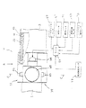
図1は、第1実施形態に係るステアリング装置の車室側部分を示す側面図であり、同図中の符号1はコラプシブルコラムを示している。コラプシブルコラム1は、共に鋼管製のアウタコラム3およびインナコラム5と衝突エネルギ吸収機構7とを構成要素としており、アウタコラム3を保持するアッパコラムブラケット9とインナコラム5を保持するロアコラムブラケット11とを介して車体側メンバ13に取り付けられている。尚、本実施形態では、アッパコラムブラケット9と車体側メンバ13との間にはアルミ合金製のカプセル15が介装されており、所定値以上の衝撃荷重が作用すると、アッパコラムブラケット9がアウタコラム3と伴に前方に離脱するようにしたが、カプセル方式以外の離脱機構を採用してもよい。
【0010】
コラプシブルコラム1は、図示しないベアリングを介して、アッパステアリングシャフト21を回動自在に保持している。アッパステアリングシャフト21の上端にはステアリングホイール23が取り付けられる一方、下端にはユニバーサルジョイント25を介してロアステアリングシャフト27が連結されている。図1中で、符号29はステアリングコラム1の上部を覆うコラムカバーを示し、符号31は車室とエンジンルームとを区画するダッシュボードを示し、符号33はコラプシブルコラム1のチルト操作に供されるチルトレバーを示している。尚、アッパステアリングシャフト21には、樹脂インジェクションやセレーション楕円嵌合等による公知の衝突エネルギ吸収機構が形成されており、運転者の二次衝突時に短縮しながら衝突エネルギを吸収する。
【0011】
このステアリング装置では、運転者がステアリングホイール23を回転させると、アッパステアリングシャフト21およびロアステアリングシャフト27を介して、その回転力が図示しないステアリングギヤに伝達される。ステアリングギヤ内には、回転入力を直線運動に変換するラックアンドピニオン機構等が内蔵されており、タイロッド等を介して車輪の舵角が変動して操舵が行われる。尚、ステアリングギヤには、ラックアンドピニオン式の他、ボールスクリュー式やウォームローラ式等、種々の形式が公知である。
【0012】
図2は図1中の拡大A矢視図であり、図3は図2中のB矢視図であり、図4は図2中のC−C断面図である。これらの図に示したように、衝突エネルギ吸収機構7は、アウタコラム3とインナコラム5との間に介装された第1金属球保持筒35と、この第1金属球保持筒35の前方に配設された第2金属球保持筒37と、第2金属球保持筒37の係止を行う保持筒係止装置39とを主要構成部材としている。
【0013】
第1金属球保持筒35および第2金属球保持筒37は、共に合成樹脂や焼結含油合金等を素材としており、それぞれに鋼球41,43を回転自在に保持する鋼球保持孔45,47を有している。本実施形態の場合、第1金属球保持筒35と第2金属球保持筒37とは図示しない係合爪により所定の係合力で結合しているが、樹脂製剪断ピン等により結合されていてもよい。
【0014】
鋼球41,43は、その外径がアウタコラム3とインナコラム5との間隙より所定量大きく設定されており、アウタコラム3とインナコラム5とが軸方向に相対移動する際に両コラム3,5の内周面や外周面に塑性溝を形成する。第1金属球保持筒35側の鋼球保持孔45と第2金属球保持筒37側の鋼球保持孔47とは回転方向で角度位相が異なっており、両鋼球41,43は互いに異なった角度位置に塑性溝を形成する。
【0015】
保持筒係止装置39は、アウタコラム3に固着されたアルミ合金や合成樹脂を素材とするハウジング51と、ハウジング51内のシリンダ53に摺動自在に保持されたピストン55と、ハウジング51の後部にねじ込まれてECU(電子制御装置)57に点火制御される電気点火式ガス発生装置(以下、インフレータと記す)59等からなっている。第2金属球保持筒37には貫通孔61が形成されており、図3の係止状態では、この貫通孔61にピストン55の中央に突設された係止ピン部63が嵌入している。図2中、符号65はハウジング51に形成されたガス通路を示しており、インフレータ59とピストン55の前面とを連絡している。
【0016】
ECU57には、シートポジションセンサ67の他、体重センサ69、車速センサ71、乗員位置センサ73、シートベルト着用センサ75等、少なくとも一つの運転状態検出センサと、衝突検出センサ77とが接続されている。衝突検出センサ77は、SRSエアバックシステム等に用いられるものを流用してもよいし、SRSエアバックシステムから直に検出信号を受けるようにしてもよい。また、衝突検出センサ77の衝突信号に、運転手の状況(シートベルト着用状態、体重、位置)や車速の検出信号を併用し、検出精度を向上させるようにしてもよい。
【0017】
ハウジング51には、コーン状の先端がピストン55の後面に係合する一対の移動防止ピン81と、移動防止ピン81をピストン55側に付勢するコイルスプリング83とが保持されており、ピストン55が不用意に移動しないように係止状態に保持している。図中、符号85で示した部材はコイルスプリング83を保持するプラグ、符号87で示した部材はピストン55の脱落を防止するプラグであり、共にハウジング51に圧入・固着されている。
【0018】
本実施形態の場合、ハウジング51には位置決め突起89が形成されており、この位置決め突起89の内側端がアウタコラム3に形成された係止孔(図示せず)に嵌入することにより、ハウジング51のアウタコラム3に対する位置決めおよび回転防止がなされる。尚、アウタコラム3へのハウジング51の固定にあたっては、ハウジング51をその内径がアウタコラム3の外径より所定量小さい円筒形状としたうえで、アウタコラム3に圧入する方法を採ってもよい。
【0019】
以下、第1実施形態の作用を述べる。
自動車が走行中に他の自動車や路上の障害物に衝突すると、ECU57には、衝突検出センサ77からの衝突信号と、前述した運転状態検出センサ67,69,71,73,75からの各種運転状態パラメータとが入力される。この際、運転者の体重が比較的大きい場合や、運転者の体重が比較的小さくても車速が大きい場合、衝突時における運転者の運動エネルギが大きくなる。そのため、ECU57は、ROM内に記憶したマップあるいは所定の演算式に基づき目標コラプス荷重を大きく設定し、保持筒係止装置39のインフレータ59に点火電流を供給する。
【0020】
ECU57から点火電流が供給されると、インフレータ59がごく短時間に大量の窒素ガスを発生させ、その窒素ガスがガス通路65を通過してピストン55の前面に流入する。すると、ピストン55は、図5に示したように、コイルスプリング83に付勢された移動防止ピン81を押しのけて瞬時に後退し、ピストン55の係止ピン部63と第2金属球保持筒37の貫通孔61との係合が外れて解除状態となる。
【0021】
一方、自動車の衝突時には、運転者が慣性によってステアリングホイール23に二次衝突し、その衝撃によって先ずアッパコラムブラケット9がアウタコラム3と伴に前方に脱落する。その後、運転者の運動エネルギによりステアリングホイール23が前方に押し付けられ、図6に示したように、インナコラム5がアウタコラム3内に進入することでコラプシブルコラム1がコラプスを開始する。尚、上述した保持筒係止装置39の作動はごく短時間で行われるため、コラプシブルコラム1がコラプスを開始する時点においては、ピストン55と第2金属球保持筒37との係合は完全に外れて解除状態となっている。
【0022】
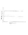
コラプシブルコラム1がコラプスを開始する際、本実施形態では、第1金属球保持筒35と第2金属球保持筒37とが連結されているため、両金属球保持筒35,37は一体となって、インナコラム5の移動量の半分の移動量をもって、アウタコラム3とインナコラム5との間を前進する。これにより、アウタコラム3の内周面とインナコラム5の外周面とには、第1金属球保持筒35側の鋼球41と第2金属球保持筒37側の鋼球43とによる塑性溝がそれぞれ形成され、比較的大きな衝撃エネルギの吸収が実現されることになる。図7はアウタコラム3の移動ストロークとコラプス荷重との関係を示すグラフであり、同図中の実線はこの際(大コラプス荷重時)の試験結果を示している。
【0023】
また、運転者が比較的体重の小さい小柄な女性等の場合、衝突時における運転者の運動エネルギは比較的小さくなる。そのため、ECU57は目標コラプス荷重を小さく設定し、インフレータ59に点火電流を供給せず、図3に示したように、ピストン55の係止ピン部63が第2金属球保持筒37の貫通孔61と係合した係止状態のままとなる。
【0024】
この状態で運転者がステアリングホイール23に二次衝突すると、上述した場合と同様のプロセスにより、アウタコラム3が脱落した後、コラプシブルコラム1がコラプスを開始する。この際、第2金属球保持筒37がピストン55により係止されているため、図8に示したように、第1金属球保持筒35と伴に後退できず(係止爪等による係合力に打ち勝って両金属球保持筒35,37が分離し)、第1金属球保持筒35側の鋼球41による塑性溝のみが形成され、衝撃エネルギの吸収量が比較的小さくなる。その結果、運転者が小柄な女性等であっても、コラプシブルコラム1のコラプスが円滑に行われ、運転者の胸部や頭部に大きな衝撃が加わることがなくなる。図7中の破線はこの際(小コラプス荷重時)の試験結果を示しており、小コラプス荷重が大コラプス荷重に対して有意に小さくなることが判る。
【0025】
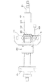
図9は、本発明の第2実施形態に係るステアリング装置を示す要部側面図である。第2実施形態は、上述した第1実施形態と略同様の構成を採っているが、保持筒係止装置39の構成が異なっている。すなわち、本実施形態では、第1実施形態とは逆に、初期状態においてピストン55と第2金属球保持筒37とが係合しておらず、インフレータ59の作動時にピストン55が前進して係止ピン部63が貫通孔61と係合するようになっている。第2実施形態の作用は、ECU57が低コラプス荷重時に点火電流をインフレータ59に供給する以外、第1実施形態と全く同様である。
【0026】
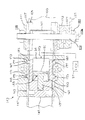
図10は、本発明の第3実施形態に係る衝撃吸収式ステアリングコラム装置を示す側面図であり、図11は同装置を示す平面図(図10中のD矢視図)であり、図12は図10中の拡大E−E断面図である。これらの図に示したように、ステアリングコラム101は、鋼管製のコラムチューブ103の略中央部に鋼板製のアッパディスタンスブラケット(以下、アッパブラケットと略称する)105を溶接接合し、同前部(図10,図11中の左方)にこれも鋼板製のロアディスタンスブラケット(以下、ロアブラケットと略称する)107を溶接接合することにより製作されている。
【0027】
アッパブラケット105は、車体側メンバ13に固着された鋼板溶接構造品のチルトブラケット111に挟持されており、チルトブラケット111を貫通するチルトボルト113とナット115とにより所定の締結力で挟圧・固定されている。アッパブラケット105には後方に開口する略U字形状の切欠き117が形成されており、チルトボルト113はこの切欠き117の前端側に嵌挿されている。図12において符号121,123で示した部材は公知のチルトカムであり、ステアリングコラム101の所定角度での固定に供される。また、符号125で示した部材はチルトカム121を回転駆動するチルトレバーであり、符号127で示した部材はチルトボルト113の頭部113aとチルトレバー125との間に介装されたスラスト軸受である。
【0028】
一方、ロアブラケット107は、車体側メンバ13に固着された鋳造品のピボットブラケット131に挟持されており、ピボットブラケット131を貫通するピボットボルト133とナット135とにより固定されている。ピボットブラケット131には前方に開口する略U字形状の切欠き137が形成されており、ピボットボルト133はこの切欠き137の後端側に嵌挿されている。尚、ステアリングコラム101は、ピボットボルト133を軸に揺動可能となっており、チルトレバー125を操作することにより運転者は所定の範囲でステアリングホイール23の上下位置を調整することができる。
【0029】
本実施形態の場合、衝突エネルギ吸収手段は、チルトボルト113に保持されたエネルギ吸収プレート141と、ステアリングコラム101に固着された可変しごき装置143とから構成されている。エネルギ吸収プレート141は、前方に開いた略U字形状の鋼板であり、後端部近傍をチルトボルト113が貫通している。
【0030】
可変しごき装置143は、図12に示したように、コラムチューブ103に溶接された鋼板プレス成形品のベースプレート145と、ベースプレート145にボルト締めされたハウジング147と、ハウジング147内に摺動自在に保持されたスライドブロック149と、ハウジング147に保持されてECU57に点火制御されるインフレータ59と、インフレータ59に連通する貫通孔151が穿設されたシリンダ153と、シリンダ153内に摺動自在に保持されたピストン155等から構成されている。
【0031】
ピストン155は、前面中央部にロッド部157が突設されており、ロッド部157の先端がスライドブロック149に係合・連結されている。尚、ECU57には、第1実施形態と同様に、シートポジションセンサ73の他、体重センサ74、車速センサ75、乗員位置センサ76、シートベルト着用センサ77等、少なくとも一つの運転状態検出センサと、衝突検出センサ77とが接続されている。
【0032】
ハウジング147には、スライドブロック149の両側面に隣接して、左右一対のガイドプレート161,163が保持されており、エネルギ吸収プレート141はこれらガイドプレート161,163とスライドブロック149との間に嵌挿されている。両ガイドプレート161,163は、略中央部と後部との内側にそれぞれU字状凹部165,167を有しており、これらU字状凹部165,167にエネルギ吸収プレート141に形成された前後のU字曲げ部171,173が嵌入している。
【0033】
エネルギ吸収プレート141には、前部U字曲げ部171に固定側しごきピン175が嵌入する一方、後部U字曲げ部173に移動側しごきピン177が嵌入している。ハウジング147には移動側しごきピン177を保持する左右一対の長孔181,183が形成されており、これら長孔181,183内を移動側しごきピン177が左右方向に所定量移動可能となっている。
【0034】
以下、第3実施形態の作用を説明する。
第3実施形態の場合、衝突時における運転者の運動エネルギが大きい場合、ECU57は目標コラプス荷重を小さく設定し、インフレータ59に点火電流を供給しない。これにより、ピストン155に連結されたスライドブロック149は後退したままとなり、その後部側面が移動側しごきピン177の内側に位置することによって、移動側しごきピン177の内側への移動を規制することになる。
【0035】
この状態で運転者が慣性によってステアリングホイール23に二次衝突すると、その衝撃によって、アッパブラケット105がチルトブラケット111から前方に離脱する一方、ロアブラケット107がピボットブラケット131から前方に離脱し、ステアリングコラム101が脱落して前進を始める。そして、ステアリングコラム101の前進に伴って、車体メンバ3側のチルトボルト113に保持されたエネルギ吸収プレート141に対して、ステアリングコラム101側の可変しごき装置143が前進する。
【0036】
すると、エネルギ吸収プレート141では、U字状凹部165と固定側しごきピン175との間に嵌入した前部U字曲げ部171と、U字状凹部167と移動側しごきピン177との間に嵌入した後部U字曲げ部173とが前進することになる。その結果、エネルギ吸収プレート141は左右4箇所で両しごきピン175,177に順次巻き回されるかたちでしごかれ、比較的大きな衝突エネルギの吸収が実現される。
【0037】
一方、運転者が比較的体重の小さい小柄な女性等の場合、衝突時における運転者の運動エネルギが比較的小さくなる。すると、ECU57は、インフレータ59に点火電流を供給する。ECU57から点火電流が供給されると、インフレータ59がごく短時間に大量の窒素ガスを発生させ、その窒素ガスがシリンダ153の貫通孔151からピストン55の後部に流入する。これにより、図13に示したように、ピストン155がスライドブロック149と伴に瞬時に前進し、移動側しごきピン177は長孔181,183内を自由に移動可能となる。
【0038】
この状態で自動車が他の自動車や路上の障害物に衝突すると、上述した場合と同様のプロセスにより、ステアリングコラム101が脱落して前進し、エネルギ吸収プレート141に対して可変しごき装置143が前進する。ところが、この場合には移動側しごきピン177がスライドブロック149により拘束されていないため、エネルギ吸収プレート141の後部U字曲げ部173は、U字状凹部167から前進・離脱する際に移動側しごきピン177を内側に押圧して移動させ、しかる後に消失する。
【0039】
その結果、エネルギ吸収プレート141は左右2箇所の固定側しごきピン175だけにしごかれることになり、衝突エネルギの吸収量が小さくなると共に、運転者が小柄な女性等であっても、ステアリングコラム101の前進が円滑に行われ、運転者の胸部や頭部に大きな衝撃が加わることがなくなるのである。
【0040】
以上で具体的実施形態の説明を終えるが、本発明の態様は上記実施形態に限られるものではない。例えば、第1実施形態では、第2金属球保持筒をピストンによりアウタコラムに係合させて、第1金属球保持筒と第2金属球保持筒とを分離させてコラプス荷重を2段階に変化させるようにしたが、インフレータやピストン、金属球保持筒等を複数組設けることでコラプス荷重を3段階以上に変化させることが可能である。その他、ステアリングコラム装置および吸収エネルギ可変手段の具体的構成等についても、本発明の主旨を逸脱しない範囲で適宜変更可能である。
【0041】
【発明の効果】
以上述べたように、請求項1の発明では、車両の衝突時における乗員の二次衝突エネルギを吸収する衝突エネルギ吸収手段を備えた衝撃吸収式ステアリングコラム装置であって、前記衝突エネルギ吸収手段による前記二次衝突エネルギの吸収量を変化させるエネルギ吸収量調整手段と、前記乗員あるいは前記車両の状態を検出する少なくとも一つの運転状態検出センサと、車両の衝突を検出する衝突検出センサと、この衝突検出センサが車両の衝突を検出した時点での前記運転状態センサの検出結果に基づき、前記エネルギ吸収量調整手段を駆動制御する電気的制御手段とを備えるようにしたため、例えば、衝突直後に各運転状態検出手段の検出結果に基づき運動エネルギを算出してROMに記憶させておいたマップや演算式等から目標コラプス荷重を設定し、エネルギ吸収量調整手段のアクチュエータに駆動電流を出力することで、衝突時における適正なコラプス荷重を得ることが可能となる。
【0042】
また、請求項2の発明では請求項1に記載の衝撃吸収式ステアリングコラム装置であって、前記エネルギ吸収量調整手段は前記電気的制御手段の駆動によりガスを発生する電気点火式ガス発生手段と該電気点火式ガス発生手段の作動・非作動に応じて二次衝突エネルギの吸収量を変化させるエネルギ吸収切換機構とを含むため、例えば、電気的制御手段が、電気点火式ガス発生手段の点火剤に電流を出力して同装置が発生したガスにコラプス荷重の切換機構を構成するピストン等を駆動させることで、コラプス荷重の切換が瞬時に行われるようになり、衝突後に最適なコラプス荷重を設定することが可能となる。
【図面の簡単な説明】
【図1】第1実施形態に係るステアリング装置の車室側部分を示す側面図である。
【図2】図1中の拡大A矢視図である。
【図3】図2中のB矢視図。
【図4】図2中のC−C断面図である。
【図5】大コラプス荷重時における保持筒係止装置の作動を示す説明図である。
【図6】大コラプス荷重時における衝突エネルギ吸収機構の作動を示す説明図である。
【図7】アウタコラムの移動ストロークとコラプス荷重との関係を示すグラフである。
【図8】少コラプス荷重時における衝突エネルギ吸収機構の作動を示す説明図である。
【図9】第2実施形態に係るステアリング装置を示す要部側面図である。
【図10】第3実施形態に係る衝撃吸収式ステアリングコラム装置を示す側面図である。
【図11】図10中のD矢視図である。
【図12】図10中の拡大E−E断面図である。
【図13】少コラプス荷重時における可変しごき装置の作動を示す説明図である。
【符号の説明】
1‥‥コラプシブルコラム
3‥‥アウタコラム
5‥‥インナコラム
7‥‥衝突エネルギ吸収機構
21‥‥アッパステアリングシャフト
35‥‥第1金属球保持筒
37‥‥第2金属球保持筒
39‥‥保持筒駆動装置
41,43‥‥鋼球
55‥‥ピストン
57‥‥ECU
59‥‥インフレータ
67‥‥シートポジションセンサ
69‥‥体重センサ
71‥‥車速センサ
73‥‥乗員位置センサ
75‥‥シートベルト着用センサ
77‥‥衝突検出センサ
101‥‥ステアリングコラム
103‥‥コラムチューブ
105‥‥アッパディスタンスブラケット
107‥‥ロアディスタンスブラケット
111‥‥チルトブラケット
113‥‥チルトボルト
131‥‥ピボットブラケット
141‥‥エネルギ吸収プレート
143‥‥可変しごき装置
149‥‥スライドブロック
155‥‥ピストン
175‥‥固定側しごきピン
177‥‥移動側しごきピン[0001]
BACKGROUND OF THE INVENTION
The present invention relates to a shock absorbing steering column device, and more particularly to a technique for switching a collapse load of a steering column at the time of a collision.
[0002]
[Prior art]
When an automobile collides with another automobile or a building, the driver may make a secondary collision with the steering wheel due to inertia. In recent passenger cars and the like, in order to prevent the driver from being damaged in such a case, an impact absorption type steering shaft and an impact absorption type steering column device are widely adopted. The shock absorption type steering column device is one in which the steering column falls off together with the steering shaft when the driver makes a secondary collision, and usually collides simultaneously with the steering shaft, and at that time, the collision energy is absorbed. As a collision energy absorbing method, as described in Japanese Patent Publication No. Sho 46-35527, a metal ball is interposed between the outer column and the inner column, and the inner peripheral surface of the outer column and the inner column are arranged during the collapse. An energy absorbing member such as a steel plate is held on either the outer column or the inner column, as described in a ball type in which a plastic groove is formed on the outer peripheral surface of the steel plate, or in JP-A-7-329796. There is known a method of squeezing and squeezing an energy absorbing member by a squeezing means such as a squeezing pin held on the other side.
[0003]
[Problems to be solved by the invention]
By the way, in the above-described shock absorption type steering column device, the steering column collapses when a predetermined collapse load is applied, and this causes the following problems. Usually, the collapse load is set based on kinetic energy when a driver with a standard weight makes a secondary collision with the steering wheel at a predetermined speed. However, when the driver is a small woman or the like, the kinetic energy naturally becomes small. Therefore, even if such a driver collides with the steering wheel at the same speed, the steering column does not collapse and the collision energy is reduced. Absorption will not occur at all. As a result, the shock absorption type steering column device cannot perform the intended action, and there is a risk that the driver may receive a large impact on the chest and head.
[0004]
In order to cope with such a problem, British Patent GB 2340457A includes a hydraulic cylinder type collision energy absorbing means, and the electronic control means calculates a target collapse load based on driving parameters output from a vehicle speed sensor, a driver weight sensor and the like. It has been proposed to switch the collapse load by changing the hydraulic oil inflow resistance of the hydraulic cylinder by calculating and adjusting the opening / closing amount of an electric valve provided in the hydraulic circuit of the collision energy absorbing means. However, this apparatus also has the following problems in terms of timing when the electronic control means calculates the target collapse load. For example, it is desirable to calculate the target collapse load based on operation parameters input from each sensor at the time of the collision, but this is not possible when using a motorized valve or an electromagnetic actuator. In other words, motorized valves and electromagnetic actuators require a relatively long time from the start to the end of operation due to their structure. Therefore, even if the drive current from the electronic control means is input after the collision, The collapse load cannot be switched in a very short time until the time of the secondary collision. Therefore, as a matter of course, the electronic control means switches the collapse load in advance before the collision, but since each operation parameter changes every moment according to the operation situation, an appropriate collapse load cannot be obtained. There was a fear.
The present invention has been made in view of the above situation, and the shock absorption type steering that switches the collapse load of the steering column at the time of the collision and enables the shock absorption at the time of the secondary collision regardless of the change of the kinetic energy of the driver. An object is to provide a column device.
[0005]
[Means for Solving the Problems]
Accordingly, in order to solve the above-mentioned problem, the invention according to
[0006]
In the present invention, the electrical control means, for example, sets the target collapse load from a map or an arithmetic expression that calculates kinetic energy based on the detection result of each driving state detection means and stores it in the ROM immediately after the collision. The drive current is output to the actuator of the energy absorption amount adjusting means.
[0007]
In the invention of claim 2, 2. The shock absorption type steering column apparatus according to
[0008]
In the present invention, for example, when the electrical control means finishes setting the target collapse load, it outputs a current to the igniter of the gas generation means, and a pin constituting a collapse load switching mechanism for the gas generated by the apparatus. Drive the cylinder.
[0009]
DETAILED DESCRIPTION OF THE INVENTION
Hereinafter, some embodiments of the present invention will be described with reference to the drawings.
FIG. 1 is a side view showing a compartment side portion of the steering apparatus according to the first embodiment, and
[0010]
The
[0011]
In this steering apparatus, when the driver rotates the steering wheel 23, the rotational force is transmitted to a steering gear (not shown) via the
[0012]
2 is an enlarged view taken along arrow A in FIG. 1, FIG. 3 is a view taken along arrow B in FIG. 2, and FIG. 4 is a cross-sectional view taken along the line CC in FIG. As shown in these drawings, the collision
[0013]
Both the first metal
[0014]
The outer diameters of the
[0015]
The holding
[0016]
In addition to the
[0017]
The
[0018]
In the case of the present embodiment, a
[0019]
The operation of the first embodiment will be described below.
When the vehicle collides with another vehicle or an obstacle on the road while the vehicle is running, the
[0020]
When the ignition current is supplied from the
[0021]
On the other hand, at the time of the collision of the automobile, the driver has a secondary collision with the steering wheel 23 due to inertia, and the upper column bracket 9 first drops together with the
[0022]
When the
[0023]
When the driver is a small woman with a relatively small weight, the kinetic energy of the driver at the time of collision is relatively small. Therefore, the
[0024]
When the driver makes a secondary collision with the steering wheel 23 in this state, the
[0025]
FIG. 9 is a side view of an essential part showing a steering apparatus according to a second embodiment of the present invention. The second embodiment has substantially the same configuration as the first embodiment described above, but the configuration of the holding
[0026]
FIG. 10 is a side view showing an impact absorption type steering column apparatus according to the third embodiment of the present invention, and FIG. 11 is a plan view showing the apparatus (as viewed from arrow D in FIG. 10). FIG. 11 is an enlarged EE sectional view in FIG. 10. As shown in these drawings, the
[0027]
The
[0028]
On the other hand, the
[0029]
In the case of the present embodiment, the collision energy absorbing means includes an
[0030]
As shown in FIG. 12, the
[0031]
The
[0032]
The
[0033]
In the
[0034]
Hereinafter, the operation of the third embodiment will be described.
In the case of the third embodiment, when the kinetic energy of the driver at the time of collision is large, the
[0035]
In this state, when the driver makes a secondary collision with the steering wheel 23 due to inertia, the
[0036]
Then, in the
[0037]
On the other hand, when the driver is a small woman with a relatively small weight, the kinetic energy of the driver at the time of collision is relatively small. Then, the
[0038]
In this state, when the automobile collides with another automobile or an obstacle on the road, the
[0039]
As a result, the
[0040]
Although description of specific embodiment is finished above, the aspect of the present invention is not limited to the above embodiment. For example, in the first embodiment, the second metal ball holding cylinder is engaged with the outer column by the piston, and the first metal ball holding cylinder and the second metal ball holding cylinder are separated to change the collapse load in two stages. However, it is possible to change the collapse load in three or more stages by providing a plurality of sets of inflators, pistons, metal ball holding cylinders, and the like. In addition, the specific configurations and the like of the steering column device and the absorbed energy varying means can be changed as appropriate without departing from the gist of the present invention.
[0041]
【The invention's effect】
As described above, according to the first aspect of the present invention, there is provided an impact absorption type steering column device including a collision energy absorbing means for absorbing a secondary collision energy of an occupant at the time of a vehicle collision. Energy absorption amount adjusting means for changing the absorption amount of the secondary collision energy, at least one driving state detection sensor for detecting the state of the occupant or the vehicle, a collision detection sensor for detecting a vehicle collision, and the collision For example, each driving immediately after a collision is provided with an electrical control unit that drives and controls the energy absorption amount adjusting unit based on the detection result of the driving state sensor when the detection sensor detects a vehicle collision. Based on the detection result of the state detection means, the kinetic energy is calculated and stored in the ROM. Set the scan load, by outputting the drive current to the actuator of the energy absorption quantity adjusting means, it is possible to obtain a proper collapse load during collision.
[0042]
In the invention of claim 2, 2. The shock absorption type steering column apparatus according to
[Brief description of the drawings]
FIG. 1 is a side view showing a compartment side portion of a steering device according to a first embodiment.
FIG. 2 is an enlarged arrow A view in FIG.
FIG. 3 is a view taken in the direction of arrow B in FIG. 2;
4 is a cross-sectional view taken along the line CC in FIG.
FIG. 5 is an explanatory view showing the operation of the holding cylinder locking device when a large collapse load is applied.
FIG. 6 is an explanatory view showing the operation of the collision energy absorbing mechanism at the time of a large collapse load.
FIG. 7 is a graph showing the relationship between the outer column movement stroke and the collapse load;
FIG. 8 is an explanatory diagram showing the operation of the collision energy absorbing mechanism at the time of a small collapse load.
FIG. 9 is a side view of an essential part showing a steering apparatus according to a second embodiment.
FIG. 10 is a side view showing an impact absorption type steering column apparatus according to a third embodiment.
FIG. 11 is a view taken in the direction of arrow D in FIG.
12 is an enlarged EE cross-sectional view in FIG.
FIG. 13 is an explanatory view showing the operation of the variable ironing device at the time of a small collapse load.
[Explanation of symbols]
1 ... Collapsible Column
3. Outer column
5 ... Inner column
7 ... Collision energy absorption mechanism
21 ... Upper steering shaft
35 ... 1st metal ball holding cylinder
37 ... 2nd metal ball holding cylinder
39 ... Holding cylinder drive
41, 43 ... Steel balls
55 ... Piston
57 ... ECU
59 ... Inflator
67 ... Seat position sensor
69 ... Weight sensor
71 ... Vehicle speed sensor
73 ... Passenger position sensor
75 ... Seat belt wearing sensor
77 ... Collision detection sensor
101 ... Steering column
103 ... Column tube
105 ... Upper distance bracket
107 ... lower distance bracket
111 ... Tilt bracket
113 ... Tilt bolt
131 Pivot bracket
141 ... Energy absorption plate
143 ... Variable ironing equipment
149 ... Slide block
155 ... Piston
175 ... Fixing side ironing pin
177 ... Moving side squeezing pin
Claims (3)
Priority Applications (4)
| Application Number | Priority Date | Filing Date | Title |
|---|---|---|---|
| JP2000259145A JP4470299B2 (en) | 2000-08-29 | 2000-08-29 | Shock absorbing steering column device |
| US09/939,567 US6631924B2 (en) | 2000-08-29 | 2001-08-28 | Shock absorbing type steering column apparatus |
| EP01307325A EP1184253B1 (en) | 2000-08-29 | 2001-08-29 | Shock absorbing type steering column apparatus |
| DE60110870T DE60110870T2 (en) | 2000-08-29 | 2001-08-29 | Shock energy receiving steering column |
Applications Claiming Priority (1)
| Application Number | Priority Date | Filing Date | Title |
|---|---|---|---|
| JP2000259145A JP4470299B2 (en) | 2000-08-29 | 2000-08-29 | Shock absorbing steering column device |
Publications (3)
| Publication Number | Publication Date |
|---|---|
| JP2002067978A JP2002067978A (en) | 2002-03-08 |
| JP2002067978A5 JP2002067978A5 (en) | 2007-08-30 |
| JP4470299B2 true JP4470299B2 (en) | 2010-06-02 |
Family
ID=18747355
Family Applications (1)
| Application Number | Title | Priority Date | Filing Date |
|---|---|---|---|
| JP2000259145A Expired - Fee Related JP4470299B2 (en) | 2000-08-29 | 2000-08-29 | Shock absorbing steering column device |
Country Status (4)
| Country | Link |
|---|---|
| US (1) | US6631924B2 (en) |
| EP (1) | EP1184253B1 (en) |
| JP (1) | JP4470299B2 (en) |
| DE (1) | DE60110870T2 (en) |
Families Citing this family (25)
| Publication number | Priority date | Publication date | Assignee | Title |
|---|---|---|---|---|
| WO2003035449A2 (en) * | 2001-10-19 | 2003-05-01 | Delphi Technologies Inc. | Responsive energy absorbing device for steering columns |
| DE10154608B4 (en) * | 2001-11-07 | 2004-10-21 | Suspa Holding Gmbh | steering damper |
| KR100482056B1 (en) * | 2001-12-19 | 2005-04-13 | 현대자동차주식회사 | a knee protecting apparatus in vehicles |
| EP1908662A3 (en) * | 2002-05-09 | 2008-05-14 | Delphi Technologies, Inc. | Adaptive energy absorption system |
| DE60332114D1 (en) * | 2002-07-10 | 2010-05-27 | Nsk Ltd | VEHICLE SHOCK ABSORPTION COLUMN DEVICE |
| US7048306B2 (en) * | 2002-09-05 | 2006-05-23 | Delphi Technologies, Inc. | Steering column with tubular structure |
| JP4124021B2 (en) | 2002-10-07 | 2008-07-23 | トヨタ自動車株式会社 | Shock absorbing steering column device |
| JP2004203164A (en) * | 2002-12-25 | 2004-07-22 | Fuji Kiko Co Ltd | Impact-absorbing structure of steering device for vehicle |
| DE10323730A1 (en) * | 2003-05-24 | 2004-12-09 | Daimlerchrysler Ag | Steering column assembly for a motor vehicle |
| US6916044B2 (en) * | 2003-07-08 | 2005-07-12 | Daimlerchrysler Corporation | Steering column/airbag tunable impact absorption system |
| US7178834B2 (en) * | 2004-05-06 | 2007-02-20 | Delphi Technologies, Inc. | Adaptive release capsule for steering column |
| US7434840B2 (en) * | 2004-06-01 | 2008-10-14 | Delphi Technologies, Inc. | Telltale indicator for adaptive energy absorbing system |
| JP2006044641A (en) * | 2004-06-28 | 2006-02-16 | Aisin Seiki Co Ltd | Shock-absorption steering apparatus |
| JP4449600B2 (en) * | 2004-06-28 | 2010-04-14 | アイシン精機株式会社 | Shock absorbing steering device |
| US20060042458A1 (en) * | 2004-09-02 | 2006-03-02 | Krj Industria E Comercio Ltda. | Device applied in electronic connectors of energy provided with unit of detonation incorporated in a button for detonation of cartridge with powder |
| US7334817B2 (en) * | 2004-09-02 | 2008-02-26 | Delphi Technologies, Inc. | Active energy absorption method using tilt and telescope positions |
| KR101047390B1 (en) | 2004-10-21 | 2011-07-07 | 주식회사 만도 | Shock absorbing structure of steering column for vehicle |
| US7347451B2 (en) * | 2004-12-16 | 2008-03-25 | Delphi Technologies, Inc. | Pre-crash column release |
| JP2007333044A (en) * | 2006-06-14 | 2007-12-27 | Daicel Chem Ind Ltd | Pyro-type actuator |
| JP4379463B2 (en) * | 2006-10-31 | 2009-12-09 | トヨタ自動車株式会社 | Knee airbag device with column |
| KR101563367B1 (en) * | 2009-05-25 | 2015-10-26 | 현대모비스 주식회사 | Collapse load adjusting device cooperated seat belt for steer column in vehicle |
| DE102010016712A1 (en) | 2010-04-30 | 2011-11-03 | Thyssenkrupp Presta Ag | Steering column for a motor vehicle |
| DE102010020088B4 (en) | 2010-05-10 | 2013-06-27 | Thyssenkrupp Presta Aktiengesellschaft | Method and device for controlling a controllable energy absorber |
| JP2015157502A (en) * | 2014-02-21 | 2015-09-03 | 株式会社ジェイテクト | steering device |
| JP6602155B2 (en) * | 2015-10-23 | 2019-11-06 | 富士機工株式会社 | Steering column device |
Family Cites Families (10)
| Publication number | Priority date | Publication date | Assignee | Title |
|---|---|---|---|---|
| JPH07329796A (en) | 1994-06-06 | 1995-12-19 | Nippon Seiko Kk | Energy absorbing plate for shock absorbing type steering device |
| SE507771C2 (en) | 1996-11-21 | 1998-07-13 | Volvo Ab | Device and method of protection of occupants in vehicles |
| DE19829238A1 (en) | 1997-06-30 | 1999-01-07 | Volkswagen Ag | Vehicle steering arrangement to increase safety of occupants |
| DE59914786D1 (en) | 1998-05-11 | 2008-07-24 | Thyssenkrupp Presta Ag | SAFETY COLUMN, SAFETY SYSTEM FOR A VEHICLE AND VEHICLE WITH A SAFETY SYSTEM AND SAFETY PROCEDURE |
| GB9817536D0 (en) | 1998-08-13 | 1998-10-07 | Rover Group | A motor vehicle |
| FR2788029B1 (en) | 1999-01-06 | 2001-02-23 | Lemforder Nacam Sa | MODULAR ENERGY ABSORPTION DEVICE FROM A AUTOMOTIVE VEHICLE STEERING COLUMN |
| GB2350329B (en) | 1999-05-26 | 2002-08-07 | Nastech Europ Ltd | Collapsible steering column assembly for a vehicle |
| GB2350328B (en) | 1999-05-26 | 2002-07-17 | Nastech Europ Ltd | Collapsible steering column assembly |
| GB2350333A (en) | 1999-05-26 | 2000-11-29 | Nastech Europ Ltd | Collapsible steering column incorporating a fluid-controlled shock absorber |
| FR2801269B1 (en) | 1999-11-19 | 2002-02-08 | Nacam | MODULAR POWER ABSORBING DEVICE WITH PYROTECHNIC LOADS FROM A STEERING COLUMN OF A MOTOR VEHICLE |
-
2000
- 2000-08-29 JP JP2000259145A patent/JP4470299B2/en not_active Expired - Fee Related
-
2001
- 2001-08-28 US US09/939,567 patent/US6631924B2/en not_active Expired - Lifetime
- 2001-08-29 DE DE60110870T patent/DE60110870T2/en not_active Expired - Lifetime
- 2001-08-29 EP EP01307325A patent/EP1184253B1/en not_active Expired - Lifetime
Also Published As
| Publication number | Publication date |
|---|---|
| DE60110870D1 (en) | 2005-06-23 |
| US20020024210A1 (en) | 2002-02-28 |
| EP1184253B1 (en) | 2005-05-18 |
| JP2002067978A (en) | 2002-03-08 |
| US6631924B2 (en) | 2003-10-14 |
| EP1184253A1 (en) | 2002-03-06 |
| DE60110870T2 (en) | 2006-01-12 |
Similar Documents
| Publication | Publication Date | Title |
|---|---|---|
| JP4470299B2 (en) | Shock absorbing steering column device | |
| US6726248B2 (en) | Impact absorbing type steering column apparatus | |
| US6641167B2 (en) | Responsive E/A system for steering columns | |
| US20020024209A1 (en) | Collapsible steering column and method | |
| JP2004082868A (en) | Shock absorbing type steering column device | |
| JP2002137743A (en) | Impact absorbing type steering column device | |
| US5984355A (en) | Steering column angle | |
| WO2005005231A1 (en) | Steering device | |
| JP2002079944A (en) | Impact absorbing steering column device | |
| CN108945111A (en) | It is a kind of for protecting the front panel structure of copilot foot | |
| JP4083653B2 (en) | Active knee bolster | |
| JP2002114157A (en) | Shock absorbing type steering column device | |
| JP2008132986A (en) | Impact absorbing type steering column apparatus | |
| JP2002067980A (en) | Impact absorbing steering column device | |
| JP2002067979A (en) | Impact absorbing steering column device | |
| JP2005126059A (en) | Shock absorbing type steering column device for vehicle | |
| JP2002362380A (en) | Impact absorbing type steering column device | |
| JP2008132987A (en) | Impact absorbing type steering column apparatus | |
| WO2022223364A1 (en) | Steering arrangement with displaceable airbag module, motor vehicle comprising such a steering arrangement and method for protecting a driver | |
| JP2002225728A (en) | Shock absorption type steering column device | |
| KR100211697B1 (en) | Tilt apparatus of steering system | |
| JP2568605Y2 (en) | Automotive steering system | |
| JP2005067264A (en) | Impact absorbing type steering column device for vehicle | |
| JP2002114156A (en) | Steering column device | |
| JP2002114159A (en) | Steering column device |
Legal Events
| Date | Code | Title | Description |
|---|---|---|---|
| A521 | Written amendment |
Free format text: JAPANESE INTERMEDIATE CODE: A523 Effective date: 20070711 |
|
| A621 | Written request for application examination |
Free format text: JAPANESE INTERMEDIATE CODE: A621 Effective date: 20070711 |
|
| A977 | Report on retrieval |
Free format text: JAPANESE INTERMEDIATE CODE: A971007 Effective date: 20090813 |
|
| A131 | Notification of reasons for refusal |
Free format text: JAPANESE INTERMEDIATE CODE: A131 Effective date: 20090825 |
|
| A521 | Written amendment |
Free format text: JAPANESE INTERMEDIATE CODE: A523 Effective date: 20091026 |
|
| TRDD | Decision of grant or rejection written | ||
| A01 | Written decision to grant a patent or to grant a registration (utility model) |
Free format text: JAPANESE INTERMEDIATE CODE: A01 Effective date: 20100209 |
|
| A01 | Written decision to grant a patent or to grant a registration (utility model) |
Free format text: JAPANESE INTERMEDIATE CODE: A01 |
|
| A61 | First payment of annual fees (during grant procedure) |
Free format text: JAPANESE INTERMEDIATE CODE: A61 Effective date: 20100222 |
|
| FPAY | Renewal fee payment (event date is renewal date of database) |
Free format text: PAYMENT UNTIL: 20130312 Year of fee payment: 3 |
|
| R150 | Certificate of patent or registration of utility model |
Ref document number: 4470299 Country of ref document: JP Free format text: JAPANESE INTERMEDIATE CODE: R150 Free format text: JAPANESE INTERMEDIATE CODE: R150 |
|
| FPAY | Renewal fee payment (event date is renewal date of database) |
Free format text: PAYMENT UNTIL: 20130312 Year of fee payment: 3 |
|
| FPAY | Renewal fee payment (event date is renewal date of database) |
Free format text: PAYMENT UNTIL: 20140312 Year of fee payment: 4 |
|
| R250 | Receipt of annual fees |
Free format text: JAPANESE INTERMEDIATE CODE: R250 |
|
| R157 | Certificate of patent or utility model (correction) |
Free format text: JAPANESE INTERMEDIATE CODE: R157 |
|
| LAPS | Cancellation because of no payment of annual fees |