EP1549861B1 - Pyromechanisches befestigungselement - Google Patents
Pyromechanisches befestigungselement Download PDFInfo
- Publication number
- EP1549861B1 EP1549861B1 EP03788927A EP03788927A EP1549861B1 EP 1549861 B1 EP1549861 B1 EP 1549861B1 EP 03788927 A EP03788927 A EP 03788927A EP 03788927 A EP03788927 A EP 03788927A EP 1549861 B1 EP1549861 B1 EP 1549861B1
- Authority
- EP
- European Patent Office
- Prior art keywords
- fastening element
- adapter
- shell
- component
- element according
- Prior art date
- Legal status (The legal status is an assumption and is not a legal conclusion. Google has not performed a legal analysis and makes no representation as to the accuracy of the status listed.)
- Expired - Lifetime
Links
- 239000003380 propellant Substances 0.000 claims description 13
- 238000010276 construction Methods 0.000 claims 1
- 239000002184 metal Substances 0.000 abstract description 2
- 239000011324 bead Substances 0.000 description 1
- 239000002131 composite material Substances 0.000 description 1
- 239000002360 explosive Substances 0.000 description 1
- 239000000463 material Substances 0.000 description 1
- 238000000034 method Methods 0.000 description 1
- 238000003825 pressing Methods 0.000 description 1
- 239000007787 solid Substances 0.000 description 1
Images


Classifications
-
- F—MECHANICAL ENGINEERING; LIGHTING; HEATING; WEAPONS; BLASTING
- F16—ENGINEERING ELEMENTS AND UNITS; GENERAL MEASURES FOR PRODUCING AND MAINTAINING EFFECTIVE FUNCTIONING OF MACHINES OR INSTALLATIONS; THERMAL INSULATION IN GENERAL
- F16B—DEVICES FOR FASTENING OR SECURING CONSTRUCTIONAL ELEMENTS OR MACHINE PARTS TOGETHER, e.g. NAILS, BOLTS, CIRCLIPS, CLAMPS, CLIPS OR WEDGES; JOINTS OR JOINTING
- F16B19/00—Bolts without screw-thread; Pins, including deformable elements; Rivets
- F16B19/04—Rivets; Spigots or the like fastened by riveting
- F16B19/08—Hollow rivets; Multi-part rivets
- F16B19/12—Hollow rivets; Multi-part rivets fastened by fluid pressure, including by explosion
- F16B19/125—Hollow rivets; Multi-part rivets fastened by fluid pressure, including by explosion fastened by explosion
-
- B—PERFORMING OPERATIONS; TRANSPORTING
- B60—VEHICLES IN GENERAL
- B60R—VEHICLES, VEHICLE FITTINGS, OR VEHICLE PARTS, NOT OTHERWISE PROVIDED FOR
- B60R19/00—Wheel guards; Radiator guards, e.g. grilles; Obstruction removers; Fittings damping bouncing force in collisions
- B60R19/02—Bumpers, i.e. impact receiving or absorbing members for protecting vehicles or fending off blows from other vehicles or objects
- B60R19/24—Arrangements for mounting bumpers on vehicles
Definitions
- the invention relates to a pyromechanical fastening element for permanent mechanical connection of two components.
- connections are made with screws and nuts.
- screws and nuts are often difficult to access positions of the parts to be joined, so that a considerable amount of equipment, screw robots and assembly equipment is needed.
- a fastener according to the preamble of claim 1 is known from US-A-2807184 known.
- the invention is therefore based on the object to develop a pyrotechnic-acting fastener that is so deformed or changed after a targeted release energy supply due to the pressure build-up of a pyrotechnic explosive charge that components are permanently connected to each other.
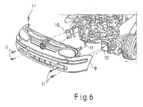
- FIG. 6 the example of a bumper front end module 9 of a motor vehicle, the technical assembly problem of hard to access screw with screws 11th
- the fully populated bumper module 9 is driven here to the bulkhead plates 10 and screwed with robot help. This assembly is expensive and time consuming.
- Another object of the invention is to find a fastener that allows for hard-to-reach mounting positions without a tool insert a solid mechanical connection.
- the element should be shaped in such a way that, on the one hand, it can be firmly premounted on one of the components to be joined and, on the other hand, permits an adjustment of the other component.
- the invention is characterized in that the fastening element consists of a metallic shell, in the head part of which a pyrotechnic propellant charge is arranged, which adjoins an adapter and at the rear part of the jacket adjacent to the adapter, a fastening means for a first component is arranged and between the first component and the adapter, a second component can be pushed, wherein the jacket has at its head portion extending in the longitudinal direction predetermined breaking notches, which tear the jacket upon ignition of the propellant charge and can bend around the adapter, whereby the first component is firmly connected to the second component ,
- the head part of the shell is preferably conical.
- the jacket of the fastener is advantageously made by deep drawing, wherein the adapter is embedded with interference fit in the jacket.
- the heat source is preferably a laser beam of a laser.
- the fastening means for the first component is preferably a beaded edge. However, any other type of attachment can be used.
- a floating disc is pushed as an abutment on the adapter adjacent to the second component advantageously.
- Fig. 1 shows a typical principle solution of the "pyromechanical fastening element" according to the invention:
- the pyromechanical fastening element consists of a shell 2 produced by the deep-drawing process with conical head part 3 as a search aid in the subsequent application.
- the jacket 2 has predetermined breaking notches 6, which ensure a targeted tearing.
- An adapter 5 terminates the charge chamber with a press fit. After loading the propellant charge 4 and pressing the adapter 5, the jacket 2 is pressed onto the adapter 5 in a form-fitting manner at the rear region.
- the element is thus prepared for pre-assembly on a component 1a.
- a bead 7 is provided for fixing the first component 1a.
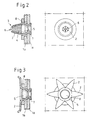
- FIG. 2 shows the fastener according to the invention preassembled on a bulkhead plate as the first component 1a and with deferred second component 1b and floating disc 8 as an abutment.
- FIG. 3 shows the fastener after the triggering of the propellant charge 4, resulting in a riveting.
- the pyromechanical fastening element is subjected to a punctiform heat source (eg laser) whose power density is so high that it punctures the sheath 2 brings to glow, ignites the propellant charge 4.
- a punctiform heat source eg laser
- a fast high pressure is generated.
- the pre-scored spreading elements of the shell 2 are highly accelerated and bend sharply due to the selected material.
- the previously loose composite is practically riveted. It can, as in the example Fig. 2 and Fig. 3 shown to be advantageous to provide a so-called "floating disc" 8 as a counter-holder to use inaccurate parts to be joined.
- FIGS. 4 and 5 show the effect of the fastener without retaining plate.
Landscapes
- Engineering & Computer Science (AREA)
- General Engineering & Computer Science (AREA)
- Physics & Mathematics (AREA)
- Fluid Mechanics (AREA)
- Mechanical Engineering (AREA)
- Connection Of Plates (AREA)
- Finger-Pressure Massage (AREA)
- Piezo-Electric Or Mechanical Vibrators, Or Delay Or Filter Circuits (AREA)
- Telephone Function (AREA)
- Insertion Pins And Rivets (AREA)
- Details Of Connecting Devices For Male And Female Coupling (AREA)
- Air Bags (AREA)
Description
- Die Erfindung betrifft ein pyromechanisches Befestigungselement zur unlösbaren festen mechanischen Verbindung zweier Bauteile.
- Bei der Montage mechanischer Bauelemente werden vorzugsweise Verbindungen mit Schrauben und Muttern hergestellt. Speziell im Automobilbau sind jedoch oft schwer zugängliche Positionen der zu verbindenden Teile gegeben, so dass ein erheblicher Aufwand an Vorrichtungen, Schraubrobotern und Montageanlagen benötigt wird.
- Ein wesentlicher Fortschritt könnte erzielt werden, wenn vor allem Teile, deren Verbindungspositionen praktisch nicht zugänglich sind, mit Befestigungselementen versehen sind, die sich nach dem Fügen aktivieren lassen und infolge einer Formänderung ein Verklemmen, Vernieten oder Verspannen der Bauteile bewirken.
- Ein Befestigungselement nach dem Oberbegriff des Anspruchs 1 ist aus der
US-A-2807184 bekannt. - Der Erfindung liegt daher die Aufgabe zugrunde, ein pyrotechnisch wirkendes Befestigungselement zu entwickeln, das nach einer gezielten Auslöseenergiezufuhr infolge des Druckaufbaus einer pyrotechnischen Explosivstoffladung so verformt oder verändert wird, dass Bauteile unlösbar fest miteinander verbunden sind.
- Die Lösung dieser Aufgabe erfolgt durch die Merkmale des Anspruchs 1.
- Zum besseren Verständnis zeigt
Fig. 6 am Beispiel eines Stoßfängerfrontendmoduls 9 eines Kraftfahrzeugs das technische Montageproblem der schwer zugänglichen Verschraubung mit Schrauben 11. - Das komplett bestückte Stoßfängermodul 9 wird hier an die Schottplatten 10 gefahren und mit Roboterhilfe verschraubt. Diese Montage ist teuer und zeitaufwendig.
- Eine weitere Aufgabe der Erfindung ist es, ein Befestigungselement zu finden, das für schwer zugängliche Montagepositionen ohne Werkzeugeinsatz eine feste mechanische Verbindung ermöglicht.
- Gleichzeitig sollte das Element so geformt sein, dass es einerseits an einem der zu fügenden Bauelemente fest vormontiert werden kann und andererseits ein Justieren des anderen Bauelements zulässt.
- Die Erfindung zeichnet sich dadurch aus, dass das Befestigungselement aus einem metallischen Mantel besteht, in dessen Kopfteil eine pyrotechnische Treibladung angeordnet ist, die an einen Adapter angrenzt und am hinteren Teil des Mantels angrenzend an den Adapter ein Befestigungsmittel für ein erstes Bauteil angeordnet ist und zwischen dem ersten Bauteil und dem Adapter ein zweites Bauteil aufschiebbar ist, wobei der Mantel an seinem Kopfteil in Längsrichtung verlaufende Sollbruchkerben aufweist, die bei Zündung der Treibladung den Mantel aufreißen und um den Adapter umbiegen lassen, wodurch das erste Bauteil mit dem zweiten Bauteil fest verbunden ist.
- Zur Suchhilfe bei der späteren Anwendung ist das Kopfteil des Mantels bevorzugt konisch ausgebildet.
- Der Mantel des Befestigungselements ist vorteilhaft im Tiefziehverfahren hergestellt, wobei der Adapter mit Presssitz im Mantel eingebettet ist.
- Zur einfachen Anzündung der pyrotechnischen Treibladung ist vorteilhafterweise die Treibladung mit einer punktförmigen Wärmequelle anzündbar, wobei die Wärmequelle bevorzugt ein Laserstrahl eines Lasers ist.
- Das Befestigungsmittel für das erste Bauteil ist bevorzugt ein Bördelrand. Es kann jedoch auch jede andere Befestigungsart verwendet werden.
- Um auch ungenauere Fügeteile verbinden zu können, ist vorteilhafterweise angrenzend an das zweite Bauteil eine schwimmende Scheibe als Gegenlager auf den Adapter aufgeschoben.
- Nachfolgend wird die Erfindung an Hand von Ausführungsbeispielen beschrieben.
-
Fig. 1 zeigt eine typische Prinziplösung des erfindungsgemäßen "Pyromechanischen Befestigungselementes": - Das pyromechanische Befestigungselement besteht aus einem nach dem Tiefziehverfahren hergestellten Mantel 2 mit konischem Kopfteil 3 als Suchhilfe bei der späteren Anwendung. Der Mantel 2 besitzt Sollbruchkerben 6, die ein gezieltes Aufreißen gewährleisten. Im vorderen Bereich ist der Treibsatz 4 angeordnet. Ein Adapter 5 schließt mit Presssitz die Ladungskammer ab. Nach dem Laden des Treibsatzes 4 und Einpressen des Adapters 5 wird der Mantel 2 am hinteren Bereich formschlüssig auf den Adapter 5 gedrückt. Das Element ist damit zur Vormontage an einem Bauteil 1a vorbereitet. Zur Befestigung des ersten Bauteils 1a ist ein Bördelrand 7 vorgesehen.
- Die
Fig. 2 (Ausführungsbeispiel 1) zeigt das erfindungsgemäße Befestigungselement vormontiert an einem Schottplattenblech als erstes Bauteil 1a und mit aufgeschobenem zweiten Bauteil 1b und schwimmender Scheibe 8 als Gegenlager.Figur 3 zeigt das Befestigungselement nach der Auslösung der Treibladung 4, wodurch sich eine Vernietung ergibt. - Wird nach dem Fügen der Blech-/Bauelementeteile das pyromechanische Befestigungselement mit einer punktförmig wirkenden Wärmequelle (z. B. Laser) beaufschlagt, deren Leistungsdichte so hoch ist, dass sie den Mantel 2 punktförmig zum Glühen bringt, entzündet sich die Treibladung 4. Je nach Art der pyrotechnischen Treibladung wird, zeitlich gesteuert, ein schneller Hochdruck erzeugt. Die vorgekerbten Spreizelemente des Mantels 2 werden hoch beschleunigt und biegen sich infolge des gezielt ausgewählten Materials scharf um. Der vorher lose Verbund wird praktisch vernietet. Es kann, wie im Beispiel
Fig. 2 und Fig. 3 gezeigt, von Vorteil sein, eine sogenannte "schwimmende Scheibe" 8 als Gegenhalter vorzusehen, um auch ungenauere Fügeteile zu verwenden. - Die
Figuren 4 und 5 zeigen die Wirkung des Befestigungselementes ohne Gegenhaltescheibe.
Claims (8)
- Pyromechanisches Befestigungselement zur unlösbaren festen mechanischen Verbindung zweier Bauteile (1a, 1b), das aus einem metallischen Mantel (2) besteht, in dessen Kopfteil (3) eine pyrotechnische Treibladung (4) angeordnet ist, dadurch gekennzeichnet, dass die Treibladung an einen Adapter (5) angrenzt und am hinteren Teil des Mantels (2) angrenzend an den Adapter (5) ein Befestigungsmittel für ein erstes Bauteil (1 a) angeordnet ist und über den Kopfteil (3) und den darin angeordneten Adapter (5) ein zweites Bauteil (1 b) aufschiebbar ist, wobei der Mantel (2) an seinem Kopfteil (3) in Längsrichtung verlaufende Sollbruchkerben (6) aufweist, die bei Zündung der Treibladung (4) den Mantel (2) aufreißen und um den Adapter (5) umbiegen lassen, wodurch das erste Bauteil (1 a) mit dem zweiten Bauteil (1 b) fest verbunden ist.
- Befestigungselement nach Anspruch 1, dadurch gekennzeichnet, dass das Kopfteil (3) des Mantels (2) konisch ausgebildet ist.
- Befestigungselement nach Anspruch 1 oder 2, dadurch gekennzeichnet, dass der Mantel (2) im Tiefziehverfahren hergestellt ist.
- Befestigungselement nach einem der Ansprüche 1 bis 3, dadurch gekennzeichnet, dass der Adapter (5) mit Presssitz im Mantel (2) eingebettet ist.
- Befestigungselement nach einem der Ansprüche 1 bis 4, dadurch gekennzeichnet, dass die pyrotechnische Treibladung (4) mit einer punktförmigen Wärmequelle anzündbar ist.
- Befestigungselement nach Anspruch 5, dadurch gekennzeichnet, dass die Wärmequelle ein Laserstrahl eines Lasers ist.
- Befestigungselement nach einem der Ansprüche 1 bis 6, dadurch gekennzeichnet, dass das Befestigungsmittel ein Bördelrand (7) ist.
- Befestigungselement nach einem der Ansprüche 1 bis 7, dadurch gekennzeichnet, dass angrenzend an das zweite Bauteil (16) eine schwimmende Scheibe (8) als Gegenlager auf den Adapter (5) aufgeschoben ist.
Applications Claiming Priority (5)
| Application Number | Priority Date | Filing Date | Title |
|---|---|---|---|
| DE10246028 | 2002-10-02 | ||
| DE10246028 | 2002-10-02 | ||
| DE10338394 | 2003-08-21 | ||
| DE10338394A DE10338394A1 (de) | 2002-10-02 | 2003-08-21 | Pyromechanisches Befestigungselement |
| PCT/EP2003/010828 WO2004033922A2 (de) | 2002-10-02 | 2003-09-30 | Pyromechanisches befestigungselement |
Publications (2)
| Publication Number | Publication Date |
|---|---|
| EP1549861A2 EP1549861A2 (de) | 2005-07-06 |
| EP1549861B1 true EP1549861B1 (de) | 2008-12-03 |
Family
ID=32094622
Family Applications (1)
| Application Number | Title | Priority Date | Filing Date |
|---|---|---|---|
| EP03788927A Expired - Lifetime EP1549861B1 (de) | 2002-10-02 | 2003-09-30 | Pyromechanisches befestigungselement |
Country Status (8)
| Country | Link |
|---|---|
| US (1) | US20060110233A1 (de) |
| EP (1) | EP1549861B1 (de) |
| JP (1) | JP4354951B2 (de) |
| AT (1) | ATE416318T1 (de) |
| AU (1) | AU2003293591A1 (de) |
| DE (2) | DE10338394A1 (de) |
| ES (1) | ES2315556T3 (de) |
| WO (1) | WO2004033922A2 (de) |
Families Citing this family (1)
| Publication number | Priority date | Publication date | Assignee | Title |
|---|---|---|---|---|
| ES2322279T3 (es) | 2004-01-21 | 2009-06-18 | Delphi Technologies, Inc. | Acoplamiento por presion no destructiva en elementos de fijacion piromecanicos. |
Family Cites Families (16)
| Publication number | Priority date | Publication date | Assignee | Title |
|---|---|---|---|---|
| US1382906A (en) * | 1920-05-11 | 1921-06-28 | Thomson Electric Welding Compa | Self-heating rivet and method of riveting with same |
| NL43339C (de) * | 1934-12-18 | |||
| US2387742A (en) * | 1942-08-12 | 1945-10-30 | Du Pont | Explosion rivet |
| US2398633A (en) * | 1943-06-14 | 1946-04-16 | Gazda Antoine | Bolt and nut assembly |
| US2378118A (en) * | 1944-02-25 | 1945-06-12 | Widrich Anton | Explosive rivet |
| GB595276A (en) * | 1944-03-15 | 1947-12-01 | Du Pont | Improvements in or relating to bolts or like fastening devices |
| US2616328A (en) * | 1951-02-01 | 1952-11-04 | William F Mathias Jr | Fastener |
| NL170358B (nl) * | 1951-06-20 | Sanyo Electric Co | Inrichting voor het opnemen en weergeven van videosignalen op een magnetische band. | |
| US2807184A (en) * | 1953-08-11 | 1957-09-24 | Du Pont | Noiseless explosive rivet |
| US2842022A (en) * | 1953-11-04 | 1958-07-08 | Walter A Semmion | Explosive rivet having tubular expansion shell |
| US3166971A (en) * | 1960-11-23 | 1965-01-26 | Air Reduction | Riveting by electric discharge |
| BE669008A (de) * | 1964-09-01 | 1966-02-28 | ||
| DE3613624A1 (de) * | 1986-04-23 | 1987-10-29 | Dynamit Nobel Ag | Pyrotechnischer duebel |
| FR2713724B1 (fr) * | 1993-12-15 | 1996-01-19 | Le Bail Hubert Yvon Felix | Rivet à fermeture par dépression. |
| DE19754791A1 (de) * | 1997-12-10 | 1999-06-17 | Dynamit Nobel Ag | Aufspreizender Metalldübel mit pyrotechnischem Antrieb |
| US7008157B2 (en) * | 2001-06-21 | 2006-03-07 | Black & Decker Inc. | Explosive assisted expanding fastener |
-
2003
- 2003-08-21 DE DE10338394A patent/DE10338394A1/de not_active Withdrawn
- 2003-09-30 ES ES03788927T patent/ES2315556T3/es not_active Expired - Lifetime
- 2003-09-30 EP EP03788927A patent/EP1549861B1/de not_active Expired - Lifetime
- 2003-09-30 AU AU2003293591A patent/AU2003293591A1/en not_active Abandoned
- 2003-09-30 JP JP2005500978A patent/JP4354951B2/ja not_active Expired - Fee Related
- 2003-09-30 DE DE50310872T patent/DE50310872D1/de not_active Expired - Lifetime
- 2003-09-30 WO PCT/EP2003/010828 patent/WO2004033922A2/de not_active Ceased
- 2003-09-30 AT AT03788927T patent/ATE416318T1/de active
- 2003-09-30 US US10/530,200 patent/US20060110233A1/en not_active Abandoned
Also Published As
| Publication number | Publication date |
|---|---|
| US20060110233A1 (en) | 2006-05-25 |
| DE50310872D1 (de) | 2009-01-15 |
| AU2003293591A8 (en) | 2004-05-04 |
| JP2006502363A (ja) | 2006-01-19 |
| AU2003293591A1 (en) | 2004-05-04 |
| ES2315556T3 (es) | 2009-04-01 |
| ATE416318T1 (de) | 2008-12-15 |
| WO2004033922A2 (de) | 2004-04-22 |
| WO2004033922A3 (de) | 2005-01-13 |
| EP1549861A2 (de) | 2005-07-06 |
| JP4354951B2 (ja) | 2009-10-28 |
| DE10338394A1 (de) | 2004-04-15 |
Similar Documents
| Publication | Publication Date | Title |
|---|---|---|
| US3621732A (en) | Fastening for motor vehicle-safety steering columns | |
| DE2821374A1 (de) | Selbsthaltende kabelverankerung | |
| DE102014103796A1 (de) | System zur elastisch gemittelten Ausrichtung | |
| EP2705297B1 (de) | Leuchteinheit für fahrzeuge | |
| DE102010028323A1 (de) | Bauteilverbindung | |
| DE102010040547A1 (de) | Bauteilverbindung | |
| DE102015219086B3 (de) | Energieabsorptionselement für eine Lenksäule eines Kraftfahrzeugs und Lenksäule für ein Kraftfahrzeug | |
| DE102017209844A1 (de) | Blindnietmutter, Befestigungsanordnung mit einer Blindnietmutter und Befestigungsverfahren | |
| DE102011114306A1 (de) | Verfahren zum Fügen von wenigstens zwei FVK-Bauteilen | |
| DE102015007960A1 (de) | Batteriegehäuse für ein Kraftfahrzeug und Verfahren zum Abdichten eines Batteriegehäuses für ein Kraftfahrzeug | |
| DE4431991A1 (de) | Verfahren zum Verbinden flächiger Bauteile | |
| DE68909097T2 (de) | Verfahren zum Verbinden von einem ersten Gegenstand aus Kunststoff und einem zweiten Gegenstand durch Nieten. | |
| DE102007041910B4 (de) | Bodenplatte für eine Sensorbaugruppe, Trägerkörper zur Befestigung der Sensorbaugruppe, Sensorbaugruppe und Befestigungssystem | |
| DE69022208T2 (de) | Kantenabdeckung und deren Einbauverfahren. | |
| DE3236745C2 (de) | ||
| EP1549861A2 (de) | Pyromechanisches befestigungselement | |
| DE10060782A1 (de) | Vorrichtung zum Befestigen von zwei Bauteilen | |
| DE10114295B4 (de) | Hitzeschildbefestigungselement | |
| DE20020102U1 (de) | Pyrotechnische, gaserzeugende Vorrichtung | |
| DE19639075A1 (de) | Befestigungseinrichtung für einen Sensor | |
| DE102018215000B4 (de) | Kraftfahrzeug mit einem Verkleidungselement | |
| DE102015209252A9 (de) | Strafferantrieb für eine Sicherheitsgurteinrichtung | |
| DE102016200357B4 (de) | Verfahren zum Fügen von mindestens zwei Bauteilen mittels eines gehärteten Fügeelements | |
| DE102009040734A1 (de) | Anbindungseinrichtung und Montageverfahren zur passgenauen Anbindung einer Heckleuchte an einem Kraftfahrzeug | |
| DE10126047C5 (de) | Verbindung zweier Bauteile von Kraftfahrzeugen, insbesondere eines Aggregateträgers einer Kraftfahrzeugtür mit Aggregaten |
Legal Events
| Date | Code | Title | Description |
|---|---|---|---|
| PUAI | Public reference made under article 153(3) epc to a published international application that has entered the european phase |
Free format text: ORIGINAL CODE: 0009012 |
|
| AK | Designated contracting states |
Kind code of ref document: A2 Designated state(s): AT BE BG CH CY CZ DE DK EE ES FI FR GB GR HU IE IT LI LU MC NL PT RO SE SI SK TR |
|
| AX | Request for extension of the european patent |
Extension state: AL LT LV MK |
|
| 17P | Request for examination filed |
Effective date: 20050907 |
|
| RBV | Designated contracting states (corrected) |
Designated state(s): AT BE BG CH CY CZ DE DK EE ES FI FR GB GR HU IE IT LI LU MC NL PT RO SE SI SK TR |
|
| DAX | Request for extension of the european patent (deleted) | ||
| 17Q | First examination report despatched |
Effective date: 20080121 |
|
| GRAP | Despatch of communication of intention to grant a patent |
Free format text: ORIGINAL CODE: EPIDOSNIGR1 |
|
| GRAS | Grant fee paid |
Free format text: ORIGINAL CODE: EPIDOSNIGR3 |
|
| GRAS | Grant fee paid |
Free format text: ORIGINAL CODE: EPIDOSNIGR3 |
|
| GRAA | (expected) grant |
Free format text: ORIGINAL CODE: 0009210 |
|
| AK | Designated contracting states |
Kind code of ref document: B1 Designated state(s): AT BE BG CH CY CZ DE DK EE ES FI FR GB GR HU IE IT LI LU MC NL PT RO SE SI SK TR |
|
| REG | Reference to a national code |
Ref country code: GB Ref legal event code: FG4D Free format text: NOT ENGLISH |
|
| REG | Reference to a national code |
Ref country code: CH Ref legal event code: EP Ref country code: CH Ref legal event code: NV Representative=s name: BOVARD AG PATENTANWAELTE |
|
| REG | Reference to a national code |
Ref country code: IE Ref legal event code: FG4D Free format text: LANGUAGE OF EP DOCUMENT: GERMAN |
|
| REF | Corresponds to: |
Ref document number: 50310872 Country of ref document: DE Date of ref document: 20090115 Kind code of ref document: P |
|
| REG | Reference to a national code |
Ref country code: ES Ref legal event code: FG2A Ref document number: 2315556 Country of ref document: ES Kind code of ref document: T3 |
|
| NLV1 | Nl: lapsed or annulled due to failure to fulfill the requirements of art. 29p and 29m of the patents act | ||
| PG25 | Lapsed in a contracting state [announced via postgrant information from national office to epo] |
Ref country code: NL Free format text: LAPSE BECAUSE OF FAILURE TO SUBMIT A TRANSLATION OF THE DESCRIPTION OR TO PAY THE FEE WITHIN THE PRESCRIBED TIME-LIMIT Effective date: 20081203 Ref country code: SI Free format text: LAPSE BECAUSE OF FAILURE TO SUBMIT A TRANSLATION OF THE DESCRIPTION OR TO PAY THE FEE WITHIN THE PRESCRIBED TIME-LIMIT Effective date: 20081203 Ref country code: FI Free format text: LAPSE BECAUSE OF FAILURE TO SUBMIT A TRANSLATION OF THE DESCRIPTION OR TO PAY THE FEE WITHIN THE PRESCRIBED TIME-LIMIT Effective date: 20081203 |
|
| REG | Reference to a national code |
Ref country code: IE Ref legal event code: FD4D |
|
| PG25 | Lapsed in a contracting state [announced via postgrant information from national office to epo] |
Ref country code: EE Free format text: LAPSE BECAUSE OF FAILURE TO SUBMIT A TRANSLATION OF THE DESCRIPTION OR TO PAY THE FEE WITHIN THE PRESCRIBED TIME-LIMIT Effective date: 20081203 Ref country code: IE Free format text: LAPSE BECAUSE OF FAILURE TO SUBMIT A TRANSLATION OF THE DESCRIPTION OR TO PAY THE FEE WITHIN THE PRESCRIBED TIME-LIMIT Effective date: 20081203 Ref country code: BG Free format text: LAPSE BECAUSE OF FAILURE TO SUBMIT A TRANSLATION OF THE DESCRIPTION OR TO PAY THE FEE WITHIN THE PRESCRIBED TIME-LIMIT Effective date: 20090303 Ref country code: RO Free format text: LAPSE BECAUSE OF FAILURE TO SUBMIT A TRANSLATION OF THE DESCRIPTION OR TO PAY THE FEE WITHIN THE PRESCRIBED TIME-LIMIT Effective date: 20081203 |
|
| PG25 | Lapsed in a contracting state [announced via postgrant information from national office to epo] |
Ref country code: PT Free format text: LAPSE BECAUSE OF FAILURE TO SUBMIT A TRANSLATION OF THE DESCRIPTION OR TO PAY THE FEE WITHIN THE PRESCRIBED TIME-LIMIT Effective date: 20090504 Ref country code: SE Free format text: LAPSE BECAUSE OF FAILURE TO SUBMIT A TRANSLATION OF THE DESCRIPTION OR TO PAY THE FEE WITHIN THE PRESCRIBED TIME-LIMIT Effective date: 20090303 |
|
| PG25 | Lapsed in a contracting state [announced via postgrant information from national office to epo] |
Ref country code: SK Free format text: LAPSE BECAUSE OF FAILURE TO SUBMIT A TRANSLATION OF THE DESCRIPTION OR TO PAY THE FEE WITHIN THE PRESCRIBED TIME-LIMIT Effective date: 20081203 |
|
| PLBE | No opposition filed within time limit |
Free format text: ORIGINAL CODE: 0009261 |
|
| STAA | Information on the status of an ep patent application or granted ep patent |
Free format text: STATUS: NO OPPOSITION FILED WITHIN TIME LIMIT |
|
| PG25 | Lapsed in a contracting state [announced via postgrant information from national office to epo] |
Ref country code: DK Free format text: LAPSE BECAUSE OF FAILURE TO SUBMIT A TRANSLATION OF THE DESCRIPTION OR TO PAY THE FEE WITHIN THE PRESCRIBED TIME-LIMIT Effective date: 20081203 |
|
| 26N | No opposition filed |
Effective date: 20090904 |
|
| BERE | Be: lapsed |
Owner name: DELPHI TECHNOLOGIES, INC. Effective date: 20090930 |
|
| PG25 | Lapsed in a contracting state [announced via postgrant information from national office to epo] |
Ref country code: MC Free format text: LAPSE BECAUSE OF NON-PAYMENT OF DUE FEES Effective date: 20090930 |
|
| GBPC | Gb: european patent ceased through non-payment of renewal fee |
Effective date: 20090930 |
|
| PG25 | Lapsed in a contracting state [announced via postgrant information from national office to epo] |
Ref country code: BE Free format text: LAPSE BECAUSE OF NON-PAYMENT OF DUE FEES Effective date: 20090930 |
|
| PG25 | Lapsed in a contracting state [announced via postgrant information from national office to epo] |
Ref country code: GR Free format text: LAPSE BECAUSE OF FAILURE TO SUBMIT A TRANSLATION OF THE DESCRIPTION OR TO PAY THE FEE WITHIN THE PRESCRIBED TIME-LIMIT Effective date: 20090304 |
|
| PG25 | Lapsed in a contracting state [announced via postgrant information from national office to epo] |
Ref country code: GB Free format text: LAPSE BECAUSE OF NON-PAYMENT OF DUE FEES Effective date: 20090930 |
|
| REG | Reference to a national code |
Ref country code: CH Ref legal event code: PFA Owner name: DELPHI TECHNOLOGIES, INC. Free format text: DELPHI TECHNOLOGIES, INC.#P.O. BOX 5052#TROY, MI 48007-5052 (US) -TRANSFER TO- DELPHI TECHNOLOGIES, INC.#P.O. BOX 5052#TROY, MI 48007-5052 (US) |
|
| PG25 | Lapsed in a contracting state [announced via postgrant information from national office to epo] |
Ref country code: LU Free format text: LAPSE BECAUSE OF NON-PAYMENT OF DUE FEES Effective date: 20090930 |
|
| PG25 | Lapsed in a contracting state [announced via postgrant information from national office to epo] |
Ref country code: HU Free format text: LAPSE BECAUSE OF FAILURE TO SUBMIT A TRANSLATION OF THE DESCRIPTION OR TO PAY THE FEE WITHIN THE PRESCRIBED TIME-LIMIT Effective date: 20090604 |
|
| PG25 | Lapsed in a contracting state [announced via postgrant information from national office to epo] |
Ref country code: TR Free format text: LAPSE BECAUSE OF FAILURE TO SUBMIT A TRANSLATION OF THE DESCRIPTION OR TO PAY THE FEE WITHIN THE PRESCRIBED TIME-LIMIT Effective date: 20081203 |
|
| PG25 | Lapsed in a contracting state [announced via postgrant information from national office to epo] |
Ref country code: CY Free format text: LAPSE BECAUSE OF FAILURE TO SUBMIT A TRANSLATION OF THE DESCRIPTION OR TO PAY THE FEE WITHIN THE PRESCRIBED TIME-LIMIT Effective date: 20081203 |
|
| PGFP | Annual fee paid to national office [announced via postgrant information from national office to epo] |
Ref country code: CH Payment date: 20110913 Year of fee payment: 9 |
|
| PGFP | Annual fee paid to national office [announced via postgrant information from national office to epo] |
Ref country code: AT Payment date: 20110826 Year of fee payment: 9 Ref country code: CZ Payment date: 20110830 Year of fee payment: 9 Ref country code: FR Payment date: 20110922 Year of fee payment: 9 |
|
| PGFP | Annual fee paid to national office [announced via postgrant information from national office to epo] |
Ref country code: IT Payment date: 20110921 Year of fee payment: 9 |
|
| PGFP | Annual fee paid to national office [announced via postgrant information from national office to epo] |
Ref country code: ES Payment date: 20111017 Year of fee payment: 9 |
|
| REG | Reference to a national code |
Ref country code: DE Ref legal event code: R082 Ref document number: 50310872 Country of ref document: DE |
|
| REG | Reference to a national code |
Ref country code: DE Ref legal event code: R081 Ref document number: 50310872 Country of ref document: DE Owner name: VOLKSWAGEN AKTIENGESELLSCHAFT, DE Free format text: FORMER OWNER: DELPHI TECHNOLOGIES, INC., VOLKSWAGEN AG, , US Effective date: 20120813 Ref country code: DE Ref legal event code: R081 Ref document number: 50310872 Country of ref document: DE Owner name: VOLKSWAGEN AKTIENGESELLSCHAFT, DE Free format text: FORMER OWNERS: DELPHI TECHNOLOGIES, INC., TROY, MICH., US; VOLKSWAGEN AG, 38440 WOLFSBURG, DE Effective date: 20120813 |
|
| PG25 | Lapsed in a contracting state [announced via postgrant information from national office to epo] |
Ref country code: CZ Free format text: LAPSE BECAUSE OF NON-PAYMENT OF DUE FEES Effective date: 20120930 |
|
| REG | Reference to a national code |
Ref country code: CH Ref legal event code: PL |
|
| REG | Reference to a national code |
Ref country code: AT Ref legal event code: MM01 Ref document number: 416318 Country of ref document: AT Kind code of ref document: T Effective date: 20120930 |
|
| REG | Reference to a national code |
Ref country code: FR Ref legal event code: ST Effective date: 20130531 |
|
| PG25 | Lapsed in a contracting state [announced via postgrant information from national office to epo] |
Ref country code: CH Free format text: LAPSE BECAUSE OF NON-PAYMENT OF DUE FEES Effective date: 20120930 Ref country code: LI Free format text: LAPSE BECAUSE OF NON-PAYMENT OF DUE FEES Effective date: 20120930 Ref country code: AT Free format text: LAPSE BECAUSE OF NON-PAYMENT OF DUE FEES Effective date: 20120930 |
|
| REG | Reference to a national code |
Ref country code: DE Ref legal event code: R084 Ref document number: 50310872 Country of ref document: DE Effective date: 20130622 |
|
| PG25 | Lapsed in a contracting state [announced via postgrant information from national office to epo] |
Ref country code: IT Free format text: LAPSE BECAUSE OF NON-PAYMENT OF DUE FEES Effective date: 20120930 Ref country code: FR Free format text: LAPSE BECAUSE OF NON-PAYMENT OF DUE FEES Effective date: 20121001 |
|
| REG | Reference to a national code |
Ref country code: ES Ref legal event code: FD2A Effective date: 20131018 |
|
| PG25 | Lapsed in a contracting state [announced via postgrant information from national office to epo] |
Ref country code: ES Free format text: LAPSE BECAUSE OF NON-PAYMENT OF DUE FEES Effective date: 20121001 |
|
| PGFP | Annual fee paid to national office [announced via postgrant information from national office to epo] |
Ref country code: DE Payment date: 20150930 Year of fee payment: 13 |
|
| REG | Reference to a national code |
Ref country code: DE Ref legal event code: R119 Ref document number: 50310872 Country of ref document: DE |
|
| PG25 | Lapsed in a contracting state [announced via postgrant information from national office to epo] |
Ref country code: DE Free format text: LAPSE BECAUSE OF NON-PAYMENT OF DUE FEES Effective date: 20170401 |