EP1549838B1 - Zentrifuge, insbesondere zur abscheidung von russ aus einem abgasstrom einer brennkraftmaschine - Google Patents
Zentrifuge, insbesondere zur abscheidung von russ aus einem abgasstrom einer brennkraftmaschine Download PDFInfo
- Publication number
- EP1549838B1 EP1549838B1 EP03761529A EP03761529A EP1549838B1 EP 1549838 B1 EP1549838 B1 EP 1549838B1 EP 03761529 A EP03761529 A EP 03761529A EP 03761529 A EP03761529 A EP 03761529A EP 1549838 B1 EP1549838 B1 EP 1549838B1
- Authority
- EP
- European Patent Office
- Prior art keywords
- centrifuge
- soot
- exhaust gas
- centrifuge according
- rotating body
- Prior art date
- Legal status (The legal status is an assumption and is not a legal conclusion. Google has not performed a legal analysis and makes no representation as to the accuracy of the status listed.)
- Expired - Lifetime
Links
Images



Classifications
-
- B—PERFORMING OPERATIONS; TRANSPORTING
- B04—CENTRIFUGAL APPARATUS OR MACHINES FOR CARRYING-OUT PHYSICAL OR CHEMICAL PROCESSES
- B04B—CENTRIFUGES
- B04B5/00—Other centrifuges
- B04B5/005—Centrifugal separators or filters for fluid circulation systems, e.g. for lubricant oil circulation systems
-
- B—PERFORMING OPERATIONS; TRANSPORTING
- B01—PHYSICAL OR CHEMICAL PROCESSES OR APPARATUS IN GENERAL
- B01D—SEPARATION
- B01D45/00—Separating dispersed particles from gases or vapours by gravity, inertia, or centrifugal forces
- B01D45/12—Separating dispersed particles from gases or vapours by gravity, inertia, or centrifugal forces by centrifugal forces
- B01D45/16—Separating dispersed particles from gases or vapours by gravity, inertia, or centrifugal forces by centrifugal forces generated by the winding course of the gas stream, the centrifugal forces being generated solely or partly by mechanical means, e.g. fixed swirl vanes
-
- B—PERFORMING OPERATIONS; TRANSPORTING
- B04—CENTRIFUGAL APPARATUS OR MACHINES FOR CARRYING-OUT PHYSICAL OR CHEMICAL PROCESSES
- B04B—CENTRIFUGES
- B04B5/00—Other centrifuges
- B04B5/08—Centrifuges for separating predominantly gaseous mixtures
-
- F—MECHANICAL ENGINEERING; LIGHTING; HEATING; WEAPONS; BLASTING
- F01—MACHINES OR ENGINES IN GENERAL; ENGINE PLANTS IN GENERAL; STEAM ENGINES
- F01N—GAS-FLOW SILENCERS OR EXHAUST APPARATUS FOR MACHINES OR ENGINES IN GENERAL; GAS-FLOW SILENCERS OR EXHAUST APPARATUS FOR INTERNAL-COMBUSTION ENGINES
- F01N3/00—Exhaust or silencing apparatus having means for purifying, rendering innocuous, or otherwise treating exhaust
- F01N3/02—Exhaust or silencing apparatus having means for purifying, rendering innocuous, or otherwise treating exhaust for cooling, or for removing solid constituents of, exhaust
- F01N3/021—Exhaust or silencing apparatus having means for purifying, rendering innocuous, or otherwise treating exhaust for cooling, or for removing solid constituents of, exhaust by means of filters
- F01N3/0217—Exhaust or silencing apparatus having means for purifying, rendering innocuous, or otherwise treating exhaust for cooling, or for removing solid constituents of, exhaust by means of filters the filtering elements having the form of hollow cylindrical bodies
-
- F—MECHANICAL ENGINEERING; LIGHTING; HEATING; WEAPONS; BLASTING
- F01—MACHINES OR ENGINES IN GENERAL; ENGINE PLANTS IN GENERAL; STEAM ENGINES
- F01N—GAS-FLOW SILENCERS OR EXHAUST APPARATUS FOR MACHINES OR ENGINES IN GENERAL; GAS-FLOW SILENCERS OR EXHAUST APPARATUS FOR INTERNAL-COMBUSTION ENGINES
- F01N3/00—Exhaust or silencing apparatus having means for purifying, rendering innocuous, or otherwise treating exhaust
- F01N3/02—Exhaust or silencing apparatus having means for purifying, rendering innocuous, or otherwise treating exhaust for cooling, or for removing solid constituents of, exhaust
- F01N3/021—Exhaust or silencing apparatus having means for purifying, rendering innocuous, or otherwise treating exhaust for cooling, or for removing solid constituents of, exhaust by means of filters
- F01N3/033—Exhaust or silencing apparatus having means for purifying, rendering innocuous, or otherwise treating exhaust for cooling, or for removing solid constituents of, exhaust by means of filters in combination with other devices
- F01N3/035—Exhaust or silencing apparatus having means for purifying, rendering innocuous, or otherwise treating exhaust for cooling, or for removing solid constituents of, exhaust by means of filters in combination with other devices with catalytic reactors
-
- F—MECHANICAL ENGINEERING; LIGHTING; HEATING; WEAPONS; BLASTING
- F01—MACHINES OR ENGINES IN GENERAL; ENGINE PLANTS IN GENERAL; STEAM ENGINES
- F01N—GAS-FLOW SILENCERS OR EXHAUST APPARATUS FOR MACHINES OR ENGINES IN GENERAL; GAS-FLOW SILENCERS OR EXHAUST APPARATUS FOR INTERNAL-COMBUSTION ENGINES
- F01N3/00—Exhaust or silencing apparatus having means for purifying, rendering innocuous, or otherwise treating exhaust
- F01N3/02—Exhaust or silencing apparatus having means for purifying, rendering innocuous, or otherwise treating exhaust for cooling, or for removing solid constituents of, exhaust
- F01N3/037—Exhaust or silencing apparatus having means for purifying, rendering innocuous, or otherwise treating exhaust for cooling, or for removing solid constituents of, exhaust by means of inertial or centrifugal separators, e.g. of cyclone type, optionally combined or associated with agglomerators
-
- B—PERFORMING OPERATIONS; TRANSPORTING
- B04—CENTRIFUGAL APPARATUS OR MACHINES FOR CARRYING-OUT PHYSICAL OR CHEMICAL PROCESSES
- B04B—CENTRIFUGES
- B04B5/00—Other centrifuges
- B04B5/12—Centrifuges in which rotors other than bowls generate centrifugal effects in stationary containers
- B04B2005/125—Centrifuges in which rotors other than bowls generate centrifugal effects in stationary containers the rotors comprising separating walls
-
- F—MECHANICAL ENGINEERING; LIGHTING; HEATING; WEAPONS; BLASTING
- F01—MACHINES OR ENGINES IN GENERAL; ENGINE PLANTS IN GENERAL; STEAM ENGINES
- F01N—GAS-FLOW SILENCERS OR EXHAUST APPARATUS FOR MACHINES OR ENGINES IN GENERAL; GAS-FLOW SILENCERS OR EXHAUST APPARATUS FOR INTERNAL-COMBUSTION ENGINES
- F01N2240/00—Combination or association of two or more different exhaust treating devices, or of at least one such device with an auxiliary device, not covered by indexing codes F01N2230/00 or F01N2250/00, one of the devices being
- F01N2240/20—Combination or association of two or more different exhaust treating devices, or of at least one such device with an auxiliary device, not covered by indexing codes F01N2230/00 or F01N2250/00, one of the devices being a flow director or deflector
-
- F—MECHANICAL ENGINEERING; LIGHTING; HEATING; WEAPONS; BLASTING
- F01—MACHINES OR ENGINES IN GENERAL; ENGINE PLANTS IN GENERAL; STEAM ENGINES
- F01N—GAS-FLOW SILENCERS OR EXHAUST APPARATUS FOR MACHINES OR ENGINES IN GENERAL; GAS-FLOW SILENCERS OR EXHAUST APPARATUS FOR INTERNAL-COMBUSTION ENGINES
- F01N2250/00—Combinations of different methods of purification
- F01N2250/02—Combinations of different methods of purification filtering and catalytic conversion
-
- F—MECHANICAL ENGINEERING; LIGHTING; HEATING; WEAPONS; BLASTING
- F01—MACHINES OR ENGINES IN GENERAL; ENGINE PLANTS IN GENERAL; STEAM ENGINES
- F01N—GAS-FLOW SILENCERS OR EXHAUST APPARATUS FOR MACHINES OR ENGINES IN GENERAL; GAS-FLOW SILENCERS OR EXHAUST APPARATUS FOR INTERNAL-COMBUSTION ENGINES
- F01N2250/00—Combinations of different methods of purification
- F01N2250/08—Combinations of different methods of purification filtering and inertial particulate separation
-
- F—MECHANICAL ENGINEERING; LIGHTING; HEATING; WEAPONS; BLASTING
- F01—MACHINES OR ENGINES IN GENERAL; ENGINE PLANTS IN GENERAL; STEAM ENGINES
- F01N—GAS-FLOW SILENCERS OR EXHAUST APPARATUS FOR MACHINES OR ENGINES IN GENERAL; GAS-FLOW SILENCERS OR EXHAUST APPARATUS FOR INTERNAL-COMBUSTION ENGINES
- F01N2450/00—Methods or apparatus for fitting, inserting or repairing different elements
- F01N2450/30—Removable or rechangeable blocks or cartridges, e.g. for filters
-
- F—MECHANICAL ENGINEERING; LIGHTING; HEATING; WEAPONS; BLASTING
- F01—MACHINES OR ENGINES IN GENERAL; ENGINE PLANTS IN GENERAL; STEAM ENGINES
- F01N—GAS-FLOW SILENCERS OR EXHAUST APPARATUS FOR MACHINES OR ENGINES IN GENERAL; GAS-FLOW SILENCERS OR EXHAUST APPARATUS FOR INTERNAL-COMBUSTION ENGINES
- F01N2510/00—Surface coverings
- F01N2510/06—Surface coverings for exhaust purification, e.g. catalytic reaction
- F01N2510/065—Surface coverings for exhaust purification, e.g. catalytic reaction for reducing soot ignition temperature
-
- F—MECHANICAL ENGINEERING; LIGHTING; HEATING; WEAPONS; BLASTING
- F01—MACHINES OR ENGINES IN GENERAL; ENGINE PLANTS IN GENERAL; STEAM ENGINES
- F01N—GAS-FLOW SILENCERS OR EXHAUST APPARATUS FOR MACHINES OR ENGINES IN GENERAL; GAS-FLOW SILENCERS OR EXHAUST APPARATUS FOR INTERNAL-COMBUSTION ENGINES
- F01N3/00—Exhaust or silencing apparatus having means for purifying, rendering innocuous, or otherwise treating exhaust
- F01N3/02—Exhaust or silencing apparatus having means for purifying, rendering innocuous, or otherwise treating exhaust for cooling, or for removing solid constituents of, exhaust
- F01N3/021—Exhaust or silencing apparatus having means for purifying, rendering innocuous, or otherwise treating exhaust for cooling, or for removing solid constituents of, exhaust by means of filters
- F01N3/023—Exhaust or silencing apparatus having means for purifying, rendering innocuous, or otherwise treating exhaust for cooling, or for removing solid constituents of, exhaust by means of filters using means for regenerating the filters, e.g. by burning trapped particles
Definitions
- the invention relates to a centrifuge, in particular for the separation of soot from an exhaust gas stream of an internal combustion engine.
- a centrifugal separator for soot particles wherein the soot particles accumulate on an outer circumferential surface of a housing. There are heating elements arranged to burn the soot particles.
- drive d. H. as a centrifugal drive the turbine impeller of the exhaust gas turbine is used.
- the US-PS 1,434,562 describes a centrifugal separator for the intake air of an internal combustion engine with a Tellerabscheider, at which the gas is diverted and carried out a deposition of the particles.
- the Tellerabscheider is driven by a self-propelled wind turbine, which is arranged on the output side.
- soot filter with a ceramic body, which receives the soot particles.
- an additive is used, which reduces the ignition temperature and allows burning of the ceramic body.
- the invention has for its object to provide a centrifuge, which is simple in construction, requires no additional facilities for burning the soot and has a high efficiency. This object is solved by the features of independent claim 1.
- the main advantage of the centrifuge is that it is installed directly in the pipeline of an exhaust line, has its own drive in the form of drive blades, which are arranged on the input side, and wherein the deposition is due to the centrifugal force and the flow is diverted to the output side.
- the invention provides that a plurality of Strömungsumlid prepared in the form of conical rings.
- the centrifuge can be designed in the manner of a Tellerseparators, which realizes a high separation efficiency at a high air flow.
- An embodiment of the invention provides to provide the cylindrical housing inner wall of the rotary body with a coating or a roughening, which promotes the initial adhesion and improves the adhesion of the carbon black.
- the housing inner wall with a catalytic coating, which reduces the ignition temperature of the soot.
- This catalytic coating may consist of both silver vanadate or copper vanadate containing alkali metals.
- the ignition temperature of the soot or soot particles can considerably, ie reduce to 365 ° C.
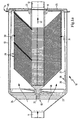
- FIG. 1a shows a soot centrifuge 10, which is designed as an inline centrifuge and is arranged between the raw gas inlet tube 11 and the clean gas outlet tube 12.
- the centrifuge is located in a housing 13, which is directly connected to Rohgaseinlassrohr and clean gas outlet and has a flange 14 which is provided with a suitable closure system 15.
- Both at the raw gas inlet and at the clean gas outlet concentric bearings 18, 19 are provided, which are the centrifuge rotor 20 wear.
- the storage is expediently a plain bearing with ceramic bushings 21, 22, which are resistant to high temperatures.
- the bearing 18 is fixed to webs 23, 24, the bearing 19 is arranged on a housing cover 25.
- the centrifuge has drive section 26 on the gas inlet side through which the centrifuge rotor is set in rotation when the exhaust gas flows in.
- the centrifuge itself is essentially a rotary body, on the housing inner wall 27 of which the deposited soot 28 can settle.
- the centrifuge further comprises StrömungsumLite adopted in the form of dishwashers 29, which cause a flow reversal of the exhaust gas.
- the centrifuge is open to the clean gas outlet pipe and under certain circumstances can also be provided there with drive blades.
- the number of plates 29 depends on the degree of separation or the separation effect and can be designed variable. Under certain circumstances, a small number of panes is sufficient to achieve the desired effect.
- the unpurified exhaust gas flows via the Rohgaseinlassrohr 11 in the outer region of the centrifuge, where it is set in rotation, so that accumulate on the centrifugal force, the soot particles on the housing inner wall 27. Subsequently, the exhaust gas flows in accordance with the arrows 30, 31 in the inner region of the centrifuge rotor and there undergoes a flow reversal and is passed to the clean gas outlet pipe 32 according to arrow.
- FIG. 1 b again clearly shows the drive via the drive blades 26 and the fixing of the bearing or the ceramic bushing 21 via four webs 23, 24, 33, 34.
- the same parts are provided with the same reference numerals.
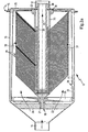
- FIG. 2a shows the variant of a soot centrifuge with a supplement.
- the difference to the centrifuge shown in Figure 1 b is that in the clean gas pipe 35, which is formed through the openings of the individual plates or the clean gas outlet pipe turned by a pipe socket 35.
- a filter cartridge 37th Magnetic Filter cartridge consists for example of a metal fleece, which is arranged on a support body.
- the filter cartridge is attached to the clean gas connection pipe 12 via a flange connection 38.
- the filter cartridge 37 has the task under certain Operating conditions, ie, for example, before starting the centrifuge to filter the soot in the exhaust gas. This soot adheres to the surface of the filter candle.
- a cleaning device is provided.
- the cleaning takes place via an air turbulence, which causes the soot to be transported back to the disk disks in the operating state of the centrifuge and from there to the housing inner wall 27.
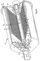
- each wings 39, 40, 41 are provided. These wings rotate with the centrifuge, d. H. they are arranged on the inner opening of the plate discs and have a small distance to the filter cartridge 37. Through these wings, the vortex flow is generated, which removes the soot from the filter cartridge 37 and removes it to the outside.
- the distance between the panes 29 to the housing inner wall 27 is extremely low.
- the relatively large diameter of the washer 29 improves the degree of separation of the soot centrifuge.
- FIG. 2b again shows a three-dimensional representation of the soot centrifuge shown in a sectional view in FIG. 2a.
- the filter cartridge 37 and its location in the clean gas pipe can be clearly seen.
- the wing 39 which is attached to the plate discs and has only a small distance from the filter cartridge 37.
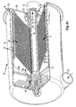
- FIG. 4 a shows a soot centrifuge, in which the drive takes place via a turbine 41.
- the turbine consists of the turbine housing 42 and the turbine wheel 43.
- the impeller is mounted in a plain bearing bushing 44 and connected to the turbine rotor.
- the turbine causes the soot separator to rotate, the raw gas flows through the turbine according to arrow 46 past the webs 47, 48 into the interior of the centrifuge rotor.
- this centrifuge is equipped with an additional filter cartridge for purifying the gas in certain operating conditions of the centrifuge.
Landscapes
- Engineering & Computer Science (AREA)
- Chemical & Material Sciences (AREA)
- Combustion & Propulsion (AREA)
- Mechanical Engineering (AREA)
- General Engineering & Computer Science (AREA)
- Chemical Kinetics & Catalysis (AREA)
- Processes For Solid Components From Exhaust (AREA)
- Cyclones (AREA)
- Exhaust Gas After Treatment (AREA)
- Centrifugal Separators (AREA)
Description
- Die Erfindung betrifft eine Zentrifuge, insbesondere zur Abscheidung von Ruß aus einem Abgasstrom einer Brennkraftmaschine.
- Aus der DE 38 30 761 ist ein Zentrifugalabscheider für Rußpartikel bekannt, wobei die Rußpartikel sich an einer äußeren Umfangsfläche eines Gehäuses anlagern. Dort sind Heizelemente angeordnet zur Verbrennung der Rußpartikel. Als Antrieb, d. h. als Fliehkraftantrieb wird das Turbinenlaufrad der Abgasturbine genutzt.
- Es ist weiterhin aus der DE 10 39 997 eine Zentrifuge mit Propellern bekannt, wobei im Inneren der Zentrifuge Mitführungsrippen angeordnet sind und Schlitze zum Ausschleudern der Verunreinigungen, d. h. der abgeschiedenen Partikel.
- Die US-PS 1,434,562 beschreibt einen Zentrifugalseparator für die Ansaugluft einer Brennkraftmaschine mit einem Tellerabscheider, an welchem das Gas umgeleitet wird und eine Abscheidung der Partikel erfolgt. Der Tellerabscheider wird angetrieben von einem als Eigenantrieb aufgebauten Windrad, das ausgangsseitig angeordnet ist.
- Bekannt ist ebenfalls ein Rußfilter mit einem Keramikkörper, welcher die Rußpartikel aufnimmt. Zur Regenerierung wird ein Additiv verwendet, welches die Zündtemperatur herabsetzt und ein Abbrennen des Keramikkörpers ermöglicht.
- Es ist femer aus der GB 1465820 A eine Zentrifuge zum Abscheiden von Ruß aus einem Abgasstrom einer Brennkraftmaschine bekannt. Diese weist einzelne Platten auf, welche perforiert sind oder Öffnungen besitzen. Das über eine Öffnung zugeführte Abgas strömt im Wesentlichen ohne Strömungsumkehr durch den Abscheider. Die im Abgas vorhandenen Partikel werden über radial angeordnete Platten nach außen geschleudert.
- Es ist weiterhin ein System bekannt, bei dem das Abgas abgelenkt und die Partikel in einer Metallmatte festgehalten werden. Dieses Filtersystem kann zwar nicht verstopfen und die Regenerierung ist bei hohen Temperaturen aufgrund der Beständigkeit des Mediums möglich, es besteht jedoch die Gefahr, dass ein Teil der Partikel ungehindert durch dieses System gelangen und ausströmen können.
- Die beschriebenen und bekannten Einrichtungen zum Abscheiden von Partikeln sind aufwendig in der Herstellung und benötigen teilweise zum Abbrennen der Partikel zusätzliche Einrichtungen wie z. B. Heizeinrichtungen.
- Der Erfindung liegt die Aufgabe zugrunde, eine Zentrifuge zu schaffen, welche einfach aufgebaut ist, keine zusätzlichen Einrichtungen zum Abbrennen des Rußes benötigt und einen hohen Wirkungsgrad aufweist. Diese Aufgabe wird durch die Merkmale des unabhängigen Anspruchs 1 gelöst.
- Der wesentliche Vorteil der Zentrifuge liegt darin, dass sie unmittelbar in der Rohrleitung eines Abgasstranges eingebaut ist, einen eigenen Antrieb aufweist in Form von Antriebsschaufeln, welche eingangsseitig angeordnet sind, und wobei die Abscheidung aufgrund der Fliehkraftwirkung erfolgt und die Strömung zur Ausgangsseite umgeleitet wird.
- Die Erfindung sieht vor, dass eine Vielzahl von Strömungsumkehreinrichtungen in Form von kegelförmigen Ringen vorgesehen ist. Damit lässt sich die Zentrifuge nach Art eines Tellerseparators gestalten, welcher bei einem hohen Luftdurchsatz eine hohe Abscheideleistung realisiert.
- Eine Ausgestaltung der Erfindung sieht vor, die zylindrische Gehäuseinnenwand des Drehkörpers mit einer Beschichtung oder einer Aufrauhung zu versehen, welche die Anfangshaftung begünstigt und das Anhaften des Rußes verbessert.
- Es wird weiterbildungsgemäß vorgeschlagen, die Gehäuseinnenwand mit einer katalytischen Beschichtung zu versehen, welche die Zündtemperatur des Rußes herabsetzt. Diese katalytische Beschichtung kann sowohl aus Silbervanadat oder aus Kupfervanadat, welches Alkalimetalle enthält, bestehen. Damit lässt sich die Zündtemperatur des Rußes bzw. der Rußpartikel beträchtlich, d. h. bis auf 365° C herabsetzen.
- Weiterbildungsgemäß wird vorgeschlagen, zur einfachen Lagerung der Zentrifuge im Rohgaseinlassrohr ein erstes Lager und im Reingasauslassrohr ein zweites Lager anzuordnen und die Zentrifuge über diese beiden Lagerstellen im Abgasstrang zu befestigen. Durch diesen Aufbau lässt sich eine Inline-Zentrifuge gestalten, die im Bereich einer Anschlussstelle im Abgasstrang vorgesehen ist bzw. ein öffenbares Gehäuse besitzt, welches in den Abgasstrang integriert ist.
- Zum Abbrennen des Rußes, d. h. zur Regenerierung besteht auch die Möglichkeit, das Abgas mit NOx anzureichern, um damit in Verbindung mit den weiteren Maßnahmen zu einer raschen und zuverlässigen Abreinigung zu gelangen.
- Diese und weitere Merkmale von bevorzugten Weiterbildungen der Erfindung gehen außer aus den Ansprüchen auch aus der Beschreibung und der Zeichnung hervor, wobei die einzelnen Merkmale jeweils für sich allein oder zu mehreren in Form von Unterkombinationen bei der Ausführungsform der Erfindung und auf anderen Gebieten verwirklicht sein und vorteilhafte sowie für sich schutzfähige Ausführungen darstellen können, für die hier Schutz beansprucht wird.
- Weitere Einzelheiten der Erfindung werden in der Zeichnung anhand von schematischen Ausführungsbeispielen beschrieben. Hierbei zeigen
- Figur 1a
- eine Schnittdarstellung durch eine Zentrifuge
- Figur 1b
- die in Figur 1a gezeigte Zentrifuge in einer 3D-Ansicht
- Figur 2a
- eine Schnittdarstellung durch eine alternativ ausgestaltete Zentrifuge
- Figur 2b
- eine dreidimensionale Ansicht der in Figur 2a gezeigten Zentrifuge
- Figur 3
- eine weitere Schnittdarstellung der in Figur 2a gezeigten Zentrifuge
- Figur 4a
- eine Schnittdarstellung einer Zentrifuge mit einer Antriebsturbine
- Figur 4b
- eine dreidimensionale Ansicht der in Figur 4a gezeigten Zentrifuge
- Figur 1a zeigt eine Rußzentrifuge 10, welche als Inline-Zentrifuge gestaltet ist und zwischen Rohgaseinlassrohr 11 und Reingasauslassrohr 12 angeordnet ist. Die Zentrifuge befindet sich in einem Gehäuse 13, welches unmittelbar mit Rohgaseinlassrohr und Reingasauslassrohr verbunden ist und eine Flanschverbindung 14 aufweist, die mit einem geeigneten Verschlusssystem 15 versehen ist. Sowohl am Rohgaseinlass als auch am Reingasauslass sind konzentrische Lager 18, 19 vorgesehen, welche den Zentrifugenrotor 20 tragen. Die Lagerung ist zweckmäßigerweise eine Gleitlagerung mit Keramikbuchsen 21, 22, welche hochtemperaturbeständig sind. Das Lager 18 ist an Stegen 23, 24 befestigt, das Lager 19 ist an einem Gehäusedeckel 25 angeordnet.
- Die Zentrifuge besitzt auf der Gaseinlassseite Antriebsschaufein 26, durch welche beim Einströmen des Abgases der Zentrifugenrotor in Rotation versetzt wird. Die Zentrifuge selbst ist im wesentlichen ein Drehkörper, an dessen Gehäuseinnenwand 27 sich der abgeschiedene Ruß 28 absetzen kann. Die Zentrifuge weist ferner Strömungsumkehreinrichtungen in Form von Tellerscheiben 29 auf, welche eine Strömungsumkehr des Abgases bewirken. Ausgangsseitig ist die Zentrifuge zum Reingasauslassrohr geöffnet und kann dort unter Umständen auch mit Antriebsschaufeln versehen sein. Die Anzahl der Tellerscheiben 29 richtet sich nach dem Abscheidegrad bzw. der Abscheidewirkung und kann variabel gestaltet sein. Unter Umständen genügt eine geringe Anzahl von Tellerscheiben, um den gewünschten Effekt zu erzielen.
- Das ungereinigte Abgas strömt über das Rohgaseinlassrohr 11 in den äußeren Bereich der Zentrifuge, wird dort in Rotation versetzt, so dass sich über die Fliehkraft die Rußpartikel an der Gehäuseinnenwand 27 anlagern. Anschließend strömt das Abgas gemäß den Pfeilen 30, 31 in den inneren Bereich des Zentrifugenrotors und erfährt dort eine Strömungsumkehr und wird zum Reingasauslassrohr gemäß Pfeil 32 geleitet.
- Zur Unterstützung der Anhaftung von Rußpartikeln an der Gehäuseinnenwand 27 kann diese aufgerauht sein. Zur Verbesserung der Abbrenneigenschaften ist diese katalytisch beschichtet. Ein Austausch der gesamten Zentrifuge ist durch ein Öffnen der Flanschverbindung 14 relativ problemlos möglich.
- Die dreidimensionale Darstellung in Figur 1 b zeigt nochmals deutlich den Antrieb über die Antriebsschaufeln 26 sowie die Fixierung des Lagers bzw. der Keramikbuchse 21 über vier Stege 23, 24, 33, 34. Gleiche Teile sind mit gleichen Bezugszeichen versehen.
- Die Figur 2a zeigt die Variante einer Rußzentrifuge mit einer Ergänzung. Zur Vermeidung von Wiederholungen, wird auf die Beschreibung der Figur 1b verwiesen. Der Unterscheid zu der in Figur 1 b gezeigten Zentrifuge liegt darin, dass sich in dem Reingasrohr 35, welches durch die Öffnungen der einzelnen Teller gebildet wird bzw. zum Reingasauslassrohr gewandt durch einen Rohrstutzen 35. In diesem befindet sich stationär angeordnet eine Filterkerze 37. Diese Filterkerze besteht beispielsweise aus einem Metallvlies, das auf einem Stützkörper angeordnet ist. Die Filterkerze ist am Reingasanschlussrohr 12 über eine Flanschverbindung 38 befestigt. Die Filterkerze 37 hat die Aufgabe, unter bestimmten Betriebszuständen, d. h. beispielsweise vor dem Anlaufen der Zentrifuge, den Ruß im Abgas abzufiltern. Dieser Ruß lagert sich an der Oberfläche der Filterkerze an. Um ein Ansammeln von Ruß auf der Filterkerze zu vermeiden, ist eine Abreinigungsvorrichtung vorgesehen. Die Abreinigung erfolgt über eine Luftverwirbelung, die dazu führt, dass im Betriebszustand der Zentrifuge der Ruß auf die Tellerscheiben zurücktransportiert wird und von dort zu der Gehäuseinnenwand 27 gelangt.
- Zur Abreinigung sind, wie in Figur 3 gezeigt, am Umfang der Filterkerze verteilt angeordnet drei Flügel 39, 40, 41 vorgesehen. Diese Flügel drehen sich mit der Zentrifuge, d. h. sie sind an der inneren Öffnung der Tellerscheiben angeordnet und weisen einen geringen Abstand zu der Filterkerze 37 auf. Durch diese Flügel wird die Wirbelströmung erzeugt, welche den Ruß von der Filterkerze 37 entfernt und nach außen abträgt.
- Wie in Figur 3 gezeigt, ist der Abstand der Tellerscheiben 29 zu der Gehäuseinnenwand 27 äußerst gering. Der relativ große Durchmesser der Tellerscheiben 29 verbessert den Abscheidegrad der Rußzentrifuge.
- Figur 2b zeigt wiederum eine dreidimensionale Darstellung der in Figur 2a in Schnittdarstellung abgebildeten Rußzentrifuge. Die Filterkerze 37 und deren Lage im Reingasrohr ist deutlich zu erkennen. Zu erkennen ist ebenfalls der Flügel 39, welcher an den Tellerscheiben befestigt ist und nur einen geringen Abstand zu der Filterkerze 37 aufweist.
- Figur 4a zeigt eine Rußzentrifuge, bei welcher der Antrieb über eine Turbine 41 erfolgt. Die Turbine besteht aus dem Turbinengehäuse 42 sowie dem Turbinenlaufrad 43. Das Laufrad ist in einer Gleitlagerbuchse 44 gelagert und mit dem Turbinenrotor verbunden.
- Beim Einströmen des rußbehafteten Abgases über den in Figur 4b gezeigten tangential angeordneten Rohgaseintritt 45 versetzt die Turbine den Rußabscheider in Drehung, das Rohgas strömt durch die Turbine gemäß Pfeil 46 an den Stegen 47, 48 vorbei in den Innenraum des Zentrifugenrotors. Auch diese Zentrifuge ist mit einer zusätzlichen Filterkerze zum Reinigen des Gases in bestimmten Betriebszuständen der Zentrifuge ausgestattet.
Claims (9)
- Zentrifuge (10) zum Abscheiden von Ruß aus einem Abgasstrom einer Brennkraftmaschine, welche als Inlinezentrifuge gestaltet ist, wobei ein Rohgaseinlassrohr (11) und ein Reingasauslassrohr (12) vorgesehen ist und die Zentrifuge (10) im Wesentlichen konzentrisch zu Einlass- und Auslassrohr (11, 12) angeordnet ist und aus einem an beiden Stirnseiten offenen Drehkörper besteht, der einlassseitig Antriebsschaufeln (26) zum Antrieb der Zentrifuge (10) aufweist, durch welche beim Einströmen des Abgases der Zentrifugenrotor (20) in Rotation versetzt wird und innerhalb des Drehkörpers eine Vielzahl von Strömungsumkehreinrichtungen in Form von kegelförmigen Ringen (29) vorgesehen ist.
- Zentrifuge nach Anspruch 1, wobei der Drehkörper eine zylindrische Gehäuseinnenwand (27) aufweist, welche eine Beschichtung zum Anhaften des Rußes aufweist.
- Zentrifuge nach Anspruch 2, wobei die Gehäuseinnenwand (27) eine katalytische Beschichtung aufweist, welche die Zündtemperatur des Rußes herabsetzt.
- Zentrifuge nach Anspruch 3, wobei die katalytische Beschichtung aus Silbervanadat oder Kupfervanadat besteht, welches Alkalimetall enthält.
- Zentrifuge nach einem der vorherigen Ansprüche, wobei im Rohgaseinlassrohr (11) ein erstes Lager (18) und im Reingasauslassrohr (12) ein zweites Lager (19) vorgesehen ist und die Zentrifuge über eine Lagerwelle durch beide Lager gehalten ist.
- Zentrifuge nach Anspruch 1, wobei diese in einem öffenbaren Gehäuse angeordnet ist.
- Zentrifuge nach einem der vorherigen Ansprüche, wobei zur Regenerierung eine NOx-Anreicherung des Abgases vorgesehen ist.
- Zentrifuge nach einem der vorherigen Ansprüche, wobei innerhalb des Drehkörpers eine Filterkerze (37) feststehend angeordnet ist, welche insbesondere aus einem Metallvlies mit einem Stützkörper besteht.
- Zentrifuge nach Anspruch 9, wobei zur Abreinigung der Filterkerze (37) wenigstens ein an den kegelförmigen Ringen (29) befestigter und sich mit diesen drehender Flügel vorgesehen ist, welcher eine Aufwirbelung des an der Filterkerze (37) anhaftenden Rußes bewirkt und sich damit der Ruß an der Gehäuseinnenwand (27) anlagert.
Applications Claiming Priority (3)
| Application Number | Priority Date | Filing Date | Title |
|---|---|---|---|
| DE10228682A DE10228682A1 (de) | 2002-06-27 | 2002-06-27 | Zentrifuge, insbesondere zur Abscheidung von Ruß aus einem Abgasstrom einer Brennkraftmaschine |
| DE10228682 | 2002-06-27 | ||
| PCT/EP2003/006781 WO2004003354A1 (de) | 2002-06-27 | 2003-06-26 | Zentrifuge, insbesondere zur abscheidung von russ aus einem abgasstrom einer brennkraftmaschine |
Publications (2)
| Publication Number | Publication Date |
|---|---|
| EP1549838A1 EP1549838A1 (de) | 2005-07-06 |
| EP1549838B1 true EP1549838B1 (de) | 2007-02-28 |
Family
ID=29761470
Family Applications (1)
| Application Number | Title | Priority Date | Filing Date |
|---|---|---|---|
| EP03761529A Expired - Lifetime EP1549838B1 (de) | 2002-06-27 | 2003-06-26 | Zentrifuge, insbesondere zur abscheidung von russ aus einem abgasstrom einer brennkraftmaschine |
Country Status (4)
| Country | Link |
|---|---|
| EP (1) | EP1549838B1 (de) |
| AT (1) | ATE355446T1 (de) |
| DE (2) | DE10228682A1 (de) |
| WO (1) | WO2004003354A1 (de) |
Cited By (2)
| Publication number | Priority date | Publication date | Assignee | Title |
|---|---|---|---|---|
| CN106194339A (zh) * | 2016-07-18 | 2016-12-07 | 深圳市金动科力实业有限公司 | 一种废气净化处理装置及柴油发电机组 |
| DE102022129043A1 (de) | 2022-11-03 | 2024-05-08 | Bayerische Motoren Werke Aktiengesellschaft | Partikelabscheider für eine Abgasanlage für ein Kraftfahrzeug, Abgasanlage und Kraftfahrzeug |
Families Citing this family (3)
| Publication number | Priority date | Publication date | Assignee | Title |
|---|---|---|---|---|
| US7250066B2 (en) | 2002-06-27 | 2007-07-31 | Mann & Hummel Gmbh | Centrifuge for separating soot from the exhaust of an internal combustion engine |
| DE202005006137U1 (de) * | 2005-04-15 | 2005-08-04 | Böhringer, Paul | Vorrichtung zum Entfernen von Rußpartikeln aus Abgasen |
| CN110953042B (zh) * | 2019-12-16 | 2021-02-09 | 海安绒克纺织有限公司 | 一种尾气处理装置 |
Family Cites Families (7)
| Publication number | Priority date | Publication date | Assignee | Title |
|---|---|---|---|---|
| US2127746A (en) * | 1936-07-31 | 1938-08-23 | Logan Engineering Co | Separator |
| FR86458E (fr) * | 1964-08-20 | 1966-02-18 | Dispositif d'évacuation des gaz de combustion | |
| DE3538107A1 (de) * | 1985-10-26 | 1987-04-30 | Man Technologie Gmbh | Filter zur reinigung von abgasen |
| DE4117602C2 (de) * | 1991-05-29 | 1995-04-13 | Ernst Apparatebau Gmbh & Co | Rußfilterkerze für Dieselmotoren |
| FR2701513B3 (fr) * | 1993-02-12 | 1995-01-20 | Lin Ching Chin | Conduite d'échappement à turbine avec filtres à gaz d'échappement et à fumée noire. |
| DE19528286C2 (de) * | 1995-08-02 | 1999-09-30 | Votech Filter Gmbh | Abscheider für mit Feststoff- oder Flüssigpartikeln beladene Gasströme |
| SE517663C2 (sv) * | 2000-10-27 | 2002-07-02 | Alfa Laval Corp Ab | Centrifugalseparator för rening av ett gasformigt fluidum |
-
2002
- 2002-06-27 DE DE10228682A patent/DE10228682A1/de not_active Withdrawn
-
2003
- 2003-06-26 EP EP03761529A patent/EP1549838B1/de not_active Expired - Lifetime
- 2003-06-26 AT AT03761529T patent/ATE355446T1/de not_active IP Right Cessation
- 2003-06-26 DE DE50306692T patent/DE50306692D1/de not_active Expired - Lifetime
- 2003-06-26 WO PCT/EP2003/006781 patent/WO2004003354A1/de not_active Ceased
Cited By (2)
| Publication number | Priority date | Publication date | Assignee | Title |
|---|---|---|---|---|
| CN106194339A (zh) * | 2016-07-18 | 2016-12-07 | 深圳市金动科力实业有限公司 | 一种废气净化处理装置及柴油发电机组 |
| DE102022129043A1 (de) | 2022-11-03 | 2024-05-08 | Bayerische Motoren Werke Aktiengesellschaft | Partikelabscheider für eine Abgasanlage für ein Kraftfahrzeug, Abgasanlage und Kraftfahrzeug |
Also Published As
| Publication number | Publication date |
|---|---|
| ATE355446T1 (de) | 2006-03-15 |
| WO2004003354A1 (de) | 2004-01-08 |
| DE50306692D1 (de) | 2007-04-12 |
| DE10228682A1 (de) | 2004-01-22 |
| EP1549838A1 (de) | 2005-07-06 |
Similar Documents
| Publication | Publication Date | Title |
|---|---|---|
| DE102011016893B4 (de) | Ölabscheider zur Abscheidung wenigstens von Öl aus einem Aerosol | |
| EP2009288A2 (de) | Turbolader mit integriertem Separator | |
| DE3219615A1 (de) | Strahlturbine mit gegenlaeufigen raedern | |
| DE2504371A1 (de) | Oelabscheider | |
| DE102007009366B4 (de) | Lüfterrad, System und Getriebebaureihe | |
| WO2012004127A1 (de) | Tesla - turbine und verfahren zu dessen betrieb | |
| DE2628300B2 (de) | Gasturbinenanlage, insbesondere für Kraftfahrzeuge wie Ackerschlepper | |
| DE102010015838A1 (de) | Ölabscheider eines Entlüftungssystems | |
| DE112014006511T5 (de) | Abgasreinigungssystem einer Maschine mit interner Verbrennung, die einen Turbolader aufweist | |
| DE102012100438A1 (de) | Abscheider für Flüssigkeitströpfchen aus einem Aerosol | |
| CH470637A (de) | Gerät zum Abscheiden eines flüssigen und/oder dampfförmigen Mediums aus einem Trägergas und dessen Verwendung in Flugzeugen | |
| CH676140A5 (de) | ||
| EP1380730B1 (de) | Schalldämpfer | |
| WO2004003354A1 (de) | Zentrifuge, insbesondere zur abscheidung von russ aus einem abgasstrom einer brennkraftmaschine | |
| DE202017002096U1 (de) | Ruß- und Feinstaubzentrifuge | |
| DE102012019419A1 (de) | Diagonal-Ventilator | |
| DE102005003037A1 (de) | Abscheidevorrichtung zum Abscheiden von Flüssigkeitspartikeln aus einem gasförmigen Medium | |
| DE102017201906B4 (de) | Dunstabzugsvorrichtung mit Filterelement | |
| DE10359966A1 (de) | Zentrifuge zum Abscheiden von Ruß aus einem Abgasstrom | |
| DE102015007410A1 (de) | Verdichter, insbesondere für einen Abgasturbolader einer Verbrennungskraftmaschine, sowie Verfahren zum Betreiben eines solchen Verdichters | |
| EP3743190A1 (de) | Filterelement, insbesondere zur gasfiltration | |
| EP1440723B1 (de) | Flüssigkeitsabscheider und Brennkraftmaschine | |
| EP2699769B1 (de) | Hydrauliklager für eine stationäre gasturbine | |
| DE102009033624A1 (de) | Lageranordnung mit einem mediengeschmierten Lager | |
| DE2460195C2 (de) | Zentrifugalabscheider |
Legal Events
| Date | Code | Title | Description |
|---|---|---|---|
| PUAI | Public reference made under article 153(3) epc to a published international application that has entered the european phase |
Free format text: ORIGINAL CODE: 0009012 |
|
| 17P | Request for examination filed |
Effective date: 20041203 |
|
| AK | Designated contracting states |
Kind code of ref document: A1 Designated state(s): AT BE BG CH CY CZ DE DK EE ES FI FR GB GR HU IE IT LI LU MC NL PT RO SE SI SK TR |
|
| GRAP | Despatch of communication of intention to grant a patent |
Free format text: ORIGINAL CODE: EPIDOSNIGR1 |
|
| GRAS | Grant fee paid |
Free format text: ORIGINAL CODE: EPIDOSNIGR3 |
|
| GRAA | (expected) grant |
Free format text: ORIGINAL CODE: 0009210 |
|
| AK | Designated contracting states |
Kind code of ref document: B1 Designated state(s): AT BE BG CH CY CZ DE DK EE ES FI FR GB GR HU IE IT LI LU MC NL PT RO SE SI SK TR |
|
| PG25 | Lapsed in a contracting state [announced via postgrant information from national office to epo] |
Ref country code: NL Free format text: LAPSE BECAUSE OF FAILURE TO SUBMIT A TRANSLATION OF THE DESCRIPTION OR TO PAY THE FEE WITHIN THE PRESCRIBED TIME-LIMIT Effective date: 20070228 Ref country code: FI Free format text: LAPSE BECAUSE OF FAILURE TO SUBMIT A TRANSLATION OF THE DESCRIPTION OR TO PAY THE FEE WITHIN THE PRESCRIBED TIME-LIMIT Effective date: 20070228 Ref country code: SI Free format text: LAPSE BECAUSE OF FAILURE TO SUBMIT A TRANSLATION OF THE DESCRIPTION OR TO PAY THE FEE WITHIN THE PRESCRIBED TIME-LIMIT Effective date: 20070228 Ref country code: IE Free format text: LAPSE BECAUSE OF FAILURE TO SUBMIT A TRANSLATION OF THE DESCRIPTION OR TO PAY THE FEE WITHIN THE PRESCRIBED TIME-LIMIT Effective date: 20070228 Ref country code: DK Free format text: LAPSE BECAUSE OF FAILURE TO SUBMIT A TRANSLATION OF THE DESCRIPTION OR TO PAY THE FEE WITHIN THE PRESCRIBED TIME-LIMIT Effective date: 20070228 |
|
| REG | Reference to a national code |
Ref country code: GB Ref legal event code: FG4D Free format text: NOT ENGLISH |
|
| GBT | Gb: translation of ep patent filed (gb section 77(6)(a)/1977) |
Effective date: 20070228 |
|
| REG | Reference to a national code |
Ref country code: CH Ref legal event code: EP |
|
| REF | Corresponds to: |
Ref document number: 50306692 Country of ref document: DE Date of ref document: 20070412 Kind code of ref document: P |
|
| REG | Reference to a national code |
Ref country code: IE Ref legal event code: FG4D Free format text: LANGUAGE OF EP DOCUMENT: GERMAN |
|
| PG25 | Lapsed in a contracting state [announced via postgrant information from national office to epo] |
Ref country code: BG Free format text: LAPSE BECAUSE OF EXPIRATION OF PROTECTION Effective date: 20070529 |
|
| PG25 | Lapsed in a contracting state [announced via postgrant information from national office to epo] |
Ref country code: SE Free format text: LAPSE BECAUSE OF FAILURE TO SUBMIT A TRANSLATION OF THE DESCRIPTION OR TO PAY THE FEE WITHIN THE PRESCRIBED TIME-LIMIT Effective date: 20070531 |
|
| PG25 | Lapsed in a contracting state [announced via postgrant information from national office to epo] |
Ref country code: ES Free format text: LAPSE BECAUSE OF FAILURE TO SUBMIT A TRANSLATION OF THE DESCRIPTION OR TO PAY THE FEE WITHIN THE PRESCRIBED TIME-LIMIT Effective date: 20070608 |
|
| PG25 | Lapsed in a contracting state [announced via postgrant information from national office to epo] |
Ref country code: PT Free format text: LAPSE BECAUSE OF FAILURE TO SUBMIT A TRANSLATION OF THE DESCRIPTION OR TO PAY THE FEE WITHIN THE PRESCRIBED TIME-LIMIT Effective date: 20070730 |
|
| NLV1 | Nl: lapsed or annulled due to failure to fulfill the requirements of art. 29p and 29m of the patents act | ||
| REG | Reference to a national code |
Ref country code: IE Ref legal event code: FD4D |
|
| PG25 | Lapsed in a contracting state [announced via postgrant information from national office to epo] |
Ref country code: SK Free format text: LAPSE BECAUSE OF FAILURE TO SUBMIT A TRANSLATION OF THE DESCRIPTION OR TO PAY THE FEE WITHIN THE PRESCRIBED TIME-LIMIT Effective date: 20070228 |
|
| BERE | Be: lapsed |
Owner name: MANN+HUMMEL G.M.B.H. Effective date: 20070630 |
|
| PG25 | Lapsed in a contracting state [announced via postgrant information from national office to epo] |
Ref country code: RO Free format text: LAPSE BECAUSE OF FAILURE TO SUBMIT A TRANSLATION OF THE DESCRIPTION OR TO PAY THE FEE WITHIN THE PRESCRIBED TIME-LIMIT Effective date: 20070228 Ref country code: CZ Free format text: LAPSE BECAUSE OF FAILURE TO SUBMIT A TRANSLATION OF THE DESCRIPTION OR TO PAY THE FEE WITHIN THE PRESCRIBED TIME-LIMIT Effective date: 20070228 |
|
| PLBE | No opposition filed within time limit |
Free format text: ORIGINAL CODE: 0009261 |
|
| STAA | Information on the status of an ep patent application or granted ep patent |
Free format text: STATUS: NO OPPOSITION FILED WITHIN TIME LIMIT |
|
| PG25 | Lapsed in a contracting state [announced via postgrant information from national office to epo] |
Ref country code: MC Free format text: LAPSE BECAUSE OF NON-PAYMENT OF DUE FEES Effective date: 20070630 |
|
| 26N | No opposition filed |
Effective date: 20071129 |
|
| REG | Reference to a national code |
Ref country code: CH Ref legal event code: PL |
|
| PG25 | Lapsed in a contracting state [announced via postgrant information from national office to epo] |
Ref country code: BE Free format text: LAPSE BECAUSE OF NON-PAYMENT OF DUE FEES Effective date: 20070630 |
|
| PG25 | Lapsed in a contracting state [announced via postgrant information from national office to epo] |
Ref country code: GR Free format text: LAPSE BECAUSE OF FAILURE TO SUBMIT A TRANSLATION OF THE DESCRIPTION OR TO PAY THE FEE WITHIN THE PRESCRIBED TIME-LIMIT Effective date: 20070529 Ref country code: CH Free format text: LAPSE BECAUSE OF NON-PAYMENT OF DUE FEES Effective date: 20070630 Ref country code: IT Free format text: LAPSE BECAUSE OF FAILURE TO SUBMIT A TRANSLATION OF THE DESCRIPTION OR TO PAY THE FEE WITHIN THE PRESCRIBED TIME-LIMIT Effective date: 20070228 Ref country code: LI Free format text: LAPSE BECAUSE OF NON-PAYMENT OF DUE FEES Effective date: 20070630 |
|
| PG25 | Lapsed in a contracting state [announced via postgrant information from national office to epo] |
Ref country code: AT Free format text: LAPSE BECAUSE OF NON-PAYMENT OF DUE FEES Effective date: 20070626 |
|
| PG25 | Lapsed in a contracting state [announced via postgrant information from national office to epo] |
Ref country code: EE Free format text: LAPSE BECAUSE OF FAILURE TO SUBMIT A TRANSLATION OF THE DESCRIPTION OR TO PAY THE FEE WITHIN THE PRESCRIBED TIME-LIMIT Effective date: 20070228 |
|
| PG25 | Lapsed in a contracting state [announced via postgrant information from national office to epo] |
Ref country code: CY Free format text: LAPSE BECAUSE OF FAILURE TO SUBMIT A TRANSLATION OF THE DESCRIPTION OR TO PAY THE FEE WITHIN THE PRESCRIBED TIME-LIMIT Effective date: 20070228 |
|
| PG25 | Lapsed in a contracting state [announced via postgrant information from national office to epo] |
Ref country code: LU Free format text: LAPSE BECAUSE OF NON-PAYMENT OF DUE FEES Effective date: 20070626 |
|
| PG25 | Lapsed in a contracting state [announced via postgrant information from national office to epo] |
Ref country code: HU Free format text: LAPSE BECAUSE OF FAILURE TO SUBMIT A TRANSLATION OF THE DESCRIPTION OR TO PAY THE FEE WITHIN THE PRESCRIBED TIME-LIMIT Effective date: 20070901 Ref country code: TR Free format text: LAPSE BECAUSE OF FAILURE TO SUBMIT A TRANSLATION OF THE DESCRIPTION OR TO PAY THE FEE WITHIN THE PRESCRIBED TIME-LIMIT Effective date: 20070228 |
|
| PGFP | Annual fee paid to national office [announced via postgrant information from national office to epo] |
Ref country code: FR Payment date: 20100706 Year of fee payment: 8 |
|
| PGFP | Annual fee paid to national office [announced via postgrant information from national office to epo] |
Ref country code: DE Payment date: 20100625 Year of fee payment: 8 Ref country code: GB Payment date: 20100618 Year of fee payment: 8 |
|
| GBPC | Gb: european patent ceased through non-payment of renewal fee |
Effective date: 20110626 |
|
| REG | Reference to a national code |
Ref country code: FR Ref legal event code: ST Effective date: 20120229 |
|
| REG | Reference to a national code |
Ref country code: DE Ref legal event code: R119 Ref document number: 50306692 Country of ref document: DE Effective date: 20120103 |
|
| PG25 | Lapsed in a contracting state [announced via postgrant information from national office to epo] |
Ref country code: DE Free format text: LAPSE BECAUSE OF NON-PAYMENT OF DUE FEES Effective date: 20120103 Ref country code: FR Free format text: LAPSE BECAUSE OF NON-PAYMENT OF DUE FEES Effective date: 20110630 |
|
| PG25 | Lapsed in a contracting state [announced via postgrant information from national office to epo] |
Ref country code: GB Free format text: LAPSE BECAUSE OF NON-PAYMENT OF DUE FEES Effective date: 20110626 |