EP1549541B1 - Fahrrad-vorderradgabel - Google Patents
Fahrrad-vorderradgabel Download PDFInfo
- Publication number
- EP1549541B1 EP1549541B1 EP03737172A EP03737172A EP1549541B1 EP 1549541 B1 EP1549541 B1 EP 1549541B1 EP 03737172 A EP03737172 A EP 03737172A EP 03737172 A EP03737172 A EP 03737172A EP 1549541 B1 EP1549541 B1 EP 1549541B1
- Authority
- EP
- European Patent Office
- Prior art keywords
- bicycle
- fork assembly
- legs
- cavity
- pair
- Prior art date
- Legal status (The legal status is an assumption and is not a legal conclusion. Google has not performed a legal analysis and makes no representation as to the accuracy of the status listed.)
- Expired - Lifetime
Links
Images


Classifications
-
- B—PERFORMING OPERATIONS; TRANSPORTING
- B62—LAND VEHICLES FOR TRAVELLING OTHERWISE THAN ON RAILS
- B62K—CYCLES; CYCLE FRAMES; CYCLE STEERING DEVICES; RIDER-OPERATED TERMINAL CONTROLS SPECIALLY ADAPTED FOR CYCLES; CYCLE AXLE SUSPENSIONS; CYCLE SIDECARS, FORECARS, OR THE LIKE
- B62K19/00—Cycle frames
- B62K19/02—Cycle frames characterised by material or cross-section of frame members
- B62K19/16—Cycle frames characterised by material or cross-section of frame members the material being wholly or mainly of plastics
-
- B—PERFORMING OPERATIONS; TRANSPORTING
- B62—LAND VEHICLES FOR TRAVELLING OTHERWISE THAN ON RAILS
- B62K—CYCLES; CYCLE FRAMES; CYCLE STEERING DEVICES; RIDER-OPERATED TERMINAL CONTROLS SPECIALLY ADAPTED FOR CYCLES; CYCLE AXLE SUSPENSIONS; CYCLE SIDECARS, FORECARS, OR THE LIKE
- B62K21/00—Steering devices
- B62K21/02—Front wheel forks or equivalent, e.g. single tine
-
- B—PERFORMING OPERATIONS; TRANSPORTING
- B62—LAND VEHICLES FOR TRAVELLING OTHERWISE THAN ON RAILS
- B62K—CYCLES; CYCLE FRAMES; CYCLE STEERING DEVICES; RIDER-OPERATED TERMINAL CONTROLS SPECIALLY ADAPTED FOR CYCLES; CYCLE AXLE SUSPENSIONS; CYCLE SIDECARS, FORECARS, OR THE LIKE
- B62K25/00—Axle suspensions
- B62K25/04—Axle suspensions for mounting axles resiliently on cycle frame or fork
-
- B—PERFORMING OPERATIONS; TRANSPORTING
- B62—LAND VEHICLES FOR TRAVELLING OTHERWISE THAN ON RAILS
- B62K—CYCLES; CYCLE FRAMES; CYCLE STEERING DEVICES; RIDER-OPERATED TERMINAL CONTROLS SPECIALLY ADAPTED FOR CYCLES; CYCLE AXLE SUSPENSIONS; CYCLE SIDECARS, FORECARS, OR THE LIKE
- B62K2201/00—Springs used in cycle frames or parts thereof
- B62K2201/02—Rubber springs
Definitions
- the present invention generally relates to bicycles. More particularly, the present invention relates to a bicycle front fork configured to reduce vibrations transmitted to a rider of the bicycle.
- Bicycle riding and racing often takes place on less than ideal terrain conditions. For example, bicycle touring and racing may often take place on country roads, which may be unpaved or where the pavement may be rough and irregular, even when new. In more populated areas, a significant portion of paved roads may be damaged and in need of repair. When traversed by the bicycle, these irregular surfaces transmit vibrations to the bicycle. Furthermore, the surface of even relatively new pavement, while acceptable for motor vehicles, may be rough enough to transmit significant vibration to a bicycle. Accordingly, most bicyclists spend at least a significant portion of their riding time traversing rough or irregular surfaces. Vibrations induced by such terrain, if not sufficiently dampened, may be transmitted to the rider of the bicycle. When transmitted to the rider, these vibrations often cause discomfort and fatigue.
- JP 08-053092 A shows a front fork according to the preamble of claim 1, having an outer tube wall which is filled with a lightweight core part.
- the bicycle may be equipped with front and/or rear suspension assemblies, which permit the suspended wheel to move against a biasing force relative to the bicycle frame.
- front and/or rear suspension assemblies which permit the suspended wheel to move against a biasing force relative to the bicycle frame.
- suspension assemblies Although highly favored in some applications, such as bicycles intended primarily for off-road use, such suspension assemblies have generally been unsuccessful in connection with bicycles primarily intended for use on paved surfaces (i.e., road bicycles), where low weight and aerodynamics are considered highly important.
- suspension assemblies are intended to absorb large bumps and may not be effective at isolating vibrations due to inherent friction within the assembly, which may prevent movement of the suspension assembly in response to small forces.
- a composite material of carbon fiber fabric within a resin matrix ('carbon fiber") is often used in an attempt to isolate road-induced vibrations from the rider of the bicycle.
- the entire frame of the bicycle may be comprised of a carbon fiber material.
- Another common method is to produce the main frame of a more conventional material, such as steel, aluminum or titanium, and provide smaller component parts of carbon fiber material in an attempt to reduce vibration.
- the front fork, seat post, handlebars, and stay portions of the frame i.e., seat stays and/or chain stays
- One proposed solution to carbon fibers undesirable transmission of vibrations is to incorporate an additional material into the carbon fiber fabric that is used to make the final carbon fiber product.
- a weave of titanium filaments has been incorporated into carbon fiber fabric in an attempt to reduce the amount of vibration that is transmitted through components made of carbon fiber.
- such a solution necessitates a complex manufacturing process and, thus, increases the cost of the final product.
- the front fork assembly of the present invention includes a cut-out portion on each leg of the fork assembly, which defines a cavity for receiving a separate vibration damping member, and preferably is constructed from a carbon fiber material.
- the vibration damping member is constructed from an elastomeric material and is retained with a friction fit within the cavity of each leg of the front fork.
- a bicycle front fork assembly includes a steer tube and a pair of fork legs extending in a downward direction from the steer tube and spaced from one another in a lateral direction.
- Each of the pair of legs has an upper portion, an intermediate portion and a lower portion and defines a substantially fixed length.
- the fork assembly is configured to support a wheel at the lower portions of the pair of legs and the pair of legs is interconnected at the upper portion.
- Each of the intermediate portions has an internal wall defining an internal cavity.
- a damping member is positioned within the cavity and contacts the internal wall. The damping member comprises a vibration damping material.
- a bicycle front fork assembly including a steer tube and a pair of hollow, tubular legs extending in a downward direction from the steer tube and spaced from one another in a lateral direction.
- Each of the pair of legs defines a substantially fixed length.
- the fork assembly is configured to support a wheel at a lower end of the pair of legs.
- Each of the legs has an outer wall portion and an internal wall portion.
- the internal wall portion extends from a first side of the outer wall portion to a second side of the outer wall portion opposite the first side.
- the internal wall portion defines an internal cavity.
- a damping member is positioned within the cavity and contacts the internal wall.
- the damping member comprises a vibration damping material.
- An embodiment of the present invention is a bicycle including a frame, which supports a pedal crank assembly and a rear wheel.
- the pedal crank assembly is configured to drive the rear wheel.
- a front fork assembly is rotatably supported by the frame for pivotal movement about a steering axis.
- the fork assembly is configured to support a front wheel of the bicycle at a lower end of the fork.
- the fork assembly includes a steer tube and a pair of hollow, tubular legs.
- the pair of legs extend in a downward direction from the steer tube and are spaced from one another in a lateral direction and define a substantially fixed length.
- Each of the pair of legs has an outer wall portion and an internal wall portion.
- the internal wall portion extends from a first side of the outer wall portion to a second side of the outer wall portion opposite the first side.
- the internal wall portion defines an internal cavity.
- a damping member is positioned within the cavity and contacts the internal wall.
- the damping member comprises a vibration damping material.
- a preferred embodiment is a bicycle including a main frame portion.
- the front wheel and the rear wheel are connected to the main frame portion.
- the pedal crank assembly is supported by the main frame.
- the front fork assembly, or wheel support portion, respectively, is connected to the main frame at a first end and supports one of the front wheel and the rear wheel at a second end.
- the pair of hollow, tubular legs of the front fork assembly extend along opposing sides of the one of the front wheel and the rear wheel.
- Figure 1 is a side elevational view of a bicycle incorporating a preferred front fork assembly.
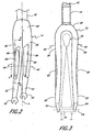
- Figure 2 is a top, left side, and rear perspective view of the front fork assembly of Figure 1.
- Figure 3 is a front view of a portion of the bicycle and front fork assembly of Figure 1.
- Figure 4 is a cross-section view of the left leg portion of the front fork assembly of Figure 1 taken along line 4-4 of Figure 2.
- Figure 5 is a partial cross-section of the left leg of the front fork assembly of Figure 1 taken along line 5-5 of Figure 4.
- Figure 6 is a partial sectional view of the left leg of the front fork assembly of Figure 1 taken along line 6-6 of Figure 2.
- FIG. 1 illustrates a bicycle, which is referred to generally by the reference numeral 10.
- the bicycle 10 includes a frame 12, which rotatably supports a wheel support, or front fork assembly 14, near a forward end of the frame 12 for rotation about a steering axis.
- a lower end of the fork assembly 14 supports a front wheel 16 of the bicycle 10.
- a handlebar assembly 18 is connected to an upper end of the fork 14 for rotating the fork assembly 14 and front wheel 16 about the steering axis of the bicycle 10.
- the handlebar assembly 18 may include one or more rider controls, such as shifting or braking controls.
- a rear wheel 20 of the bicycle 10 is supported near a rearward end of the frame 12.
- a pedal crank assembly 22 is rotatably supported by a lower portion of the frame 12.
- a drive chain 24 extends between the pedal crank assembly and the rear wheel to transfer power therebetween, as is well known in the art.
- a front brake caliper 26 is supported by the front fork assembly 14 and is configured to selectively apply a squeezing force to a rim of the front wheel 16.
- a rear brake caliper 28 is supported by the frame 12 and configured to selectively apply a squeezing force to a rim portion of the rear wheel 20.
- other types of braking systems may also be used.
- a seat post 30 extends in an upward direction from the frame 12 and supports a seat 32 on its upper end.
- the seat post 30 may be adjusted in height relative to the frame 12 to adjust a seat height of the bicycle 10.
- the frame 12 includes a main frame portion 34 and a wheel support, or rear frame portion 36.
- the rear frame portion 36 desirably includes a pair of lower legs, or chain stay members 38 (only one shown), extending on each side of the rear wheel 20 from a lower portion of the main frame 34.
- the rear frame portion 36 includes a pair of upper legs, or seat stay members 40, extending from an upper portion of the main frame 34 on each side of the rear wheel 20 and being connected to a rear end of the chain stays 38 near a hub axis of the rear wheel 20.
- the main frame 34 is constructed from a plurality of tubular, metal pieces welded together.
- the main frame 34 may be constructed from aluminum, steel or titanium tubing.
- the frame may comprise a composite material and may be constructed as a unitary piece.
- other suitable materials and/or construction methods may also be used, as will be appreciated by one of skill in the art.
- the front fork assembly 14 preferably is constructed to reduce the amount of vibration passed from the front wheel 16 to the handlebar assembly 18, and thus the rider of the bicycle 10.
- other components of the bicycle 10 may also be constructed to reduce vibration transfer.
- the seat post 30 may be constructed in a manner similar to the present fork assembly 14 to reduce the transmission of vibrations from the frame 12 to the seat 32 and, thus, the rider of the bicycle 10.
- Such a seat post 30 is described in greater detail in a copending application entitled BICYCLE SEAT POST ASSEMBLY ( WO 2004/007,269 ), which is assigned to the assignee of the present application and to which the skilled reader may refer for details.
- the fork 14 is constructed as a composite of a plurality of sheets of a carbon fiber material within an epoxy resin matrix and incorporates a vibration damping member comprised of an elastomeric material.
- the damping member comprises a thermoplastic elastomer, and more preferably a viscoelastomeric material, as is described in greater detail below.
- a steer tube 42 of the front fork assembly 14 extends through the frame 12 of the bicycle 10 and supports the handlebar assembly 18 (Figure 1) at its upper end.
- a pair of fork legs 44, 46 extend downward from the steer tube 42 on opposing sides of the front wheel 16.
- the fork legs 44, 46 are interconnected at an upper end 48, which is also connected to the steer tube 42.
- An intermediate portion 56 of the fork legs 44, 46 connects the upper portion 48 to the lower portion 52.
- each fork leg 44, 46 is a generally rigid member that defines a substantially constant length. That is, preferably, the fork assembly 14 is constructed such that relative movement between the front wheel 16 and the bicycle frame 12 is substantially prevented. Such a construction is commonly referred to as an unsuspended, or rigid, fork assembly.
- the fork legs 44, 46 and the steer tube 42 are of a one-piece construction.
- a drop out 50 is secured to a lower end 52 of each fork leg 44, 46.
- the drop outs 50 are sized and shaped to receive an axle portion of a hub 54 of the front wheel 16.
- the drop outs 50 are constructed of a metal, such as aluminum or steel, and are secured to the fork legs 44, 46 by a bonding process.
- other suitable arrangements to connect the front wheel 16 to the fork assembly 14 may also be used.
- the fork legs 44, 46 are arranged such that the hub 54 is supported on a forward side of an axis A defined by the steer tube 42. This is commonly referred to as the "rake" of the fork 14. Such an arrangement provides more stability to the handling characteristics of the bicycle 10, as is well known in the art.
- the upper portion 48 of the fork legs 44, 46 are substantially aligned with the axis A of the steer tube 42.
- the intermediate portions 56 of the fork legs 44, 46 curve in a forward direction in the such that the lower ends 52 and drop outs 50 are positioned forward of the axis of the bicycle 10.
- the fork legs 44, 46 may be substantially straight and meet the steer tube 42 at an angle such that the hub 54 of the front wheel 16 is positioned forward of the axis A.
- the intermediate portions 56 of the fork legs 44, 46 are each curved inwardly in a lateral direction (i.e., toward one another) such that a distance therebetween is narrower than a distance between the upper portions 48 of the fork legs 44, 46.
- the lower ends 52 of the fork 14 extend in an outward direction (i.e., away from one another) such that the distance therebetween is greater than the distance between the intermediate portions 56.
- Such an arrangement defines a generally hourglass-shaped space between the fork legs 44 and 46, which conforms to the cross-sectional shape of the front wheel 16 to improve the aerodynamics and vertical compliance of the fork assembly 14.
- each of the fork legs 44, 46 desirably define a cavity in which a damping member 60 is positioned.
- the damping member 60 is located within the intermediate portion 56 of each fork leg 44, 46 and, preferably, within the curve of the intermediate portion 56.
- the damping member is substantially triangular in shape in a side elevational view. Such an arrangement advantageously maximizes the contact area between the damping member 60 and the fork leg 44, 46 within the space available, which enhances vibration damping, while preserving the strength and stiffness of the fork 14, which improves handling.
- the damping member 60 is substantially solid and, preferably, is completely solid. Such an arrangement advantageously provides consistent, uniform vibration damping performance of the damping member 60.
- the cross-sectional area of the damping member 60 is great enough to effectively dampen vibrations from reaching the rider of the bicycle 10.
- the cross-sectional area of the largest portion of the damping member 60 is about 60mm 2 and, more preferably, about 120mm 2 .
- other cross-sectional dimensions may be desirable to provide a different level of vibration damping or for other applications.
- the left fork leg 46 is shown in several sectional views.
- the sectional views, and associated description of the fork leg 46, are described with reference to a coordinate system wherein a vertical, longitudinal plane extends along the length of the bicycle 10 and is substantially aligned with a plane defined by the frame 12 and wheels 16, 20.
- a vertical, lateral plane is substantially normal to the longitudinal plane and a horizontal plane is substantially normal to both the longitudinal and lateral planes.
- Figure 4 is a cross-sectional view of the fork leg 46 taken along a horizontal plane and intersecting the damping member 60.
- Figure 5 is a partial cross-sectional view of the fork leg 46 taken along a vertical, longitudinal plane and intersecting the damping member 60.
- Figure 6 is a partial cross-sectional view of the fork leg 46 taken along a vertical, lateral plane and aligned with a front surface of the damping member 60.
- the fork leg 46 is of a thin wall, hollow construction to reduce weight.
- the fork leg 46 is comprised of an outer wall portion 62, which defines an outer surface of the fork leg 46 and an internal wall portion 64, which defines a cavity 66, for receiving the damping member 60.
- the outer wall portion 62 defines front, rear, left-side and right-side wall portions of the fork leg 46.
- the outer and internal wall portions 62, 64 are continuous with one another.
- the cavity 66 is substantially triangular in shape and passes completely through the fork leg 46 in a lateral direction.
- the internal wall portion 64 is substantially parallel to an axis of rotation A R of the front wheel 16 ( Figure 3).
- Such an arrangement permits the fork leg 46 to maintain strength in a longitudinal direction (i.e., the direction in which loads are primarily imparted on the wheel 16), while incorporating the damping member 60.
- the cavity 66 may pass only partially through the fork leg 46 and may be fully or partially closed on one, or both, sides.
- a central portion 68 of the damping member 60 has a reduced thickness in a longitudinal direction such that a forward and rearward surface of the central portion 68 conforms with the curved forward and rearward portions of the wall 64 of the fork leg 46, which defines the cavity 66. That is, preferably, a width of the cavity 66 is reduced in a central portion thereof.
- the cross-section of the damping member 60 is substantially consistent throughout its length. That is, the reduced thickness of the central portion 68 preferably extends substantially the entire length of the damping member 60.
- Such an arrangement advantageously assists in retaining the damping member 60 within the cavity 66 due to the outer portions of the damping member 60 being larger than the central portion of the cavity 60.
- the damping member 60 is curved along its length to conform with both the forward and lateral curve of the fork leg 46, as described above.
- an outer surface 72 of the damping member 60 i.e., the surface opposite the wheel 16 in Figure 3 is substantially linear in a vertical direction. Such an arrangement enhances visibility of the damping member 60.
- the right fork leg 44 is substantially a mirror image of the left fork leg 46.
- the damping member 60 of the right fork leg 44 is substantially identical to that described above.
- the preferred fork assembly 14 inhibits vibrations from passing through the fork legs 44, 46.
- vibrations originating at the lower end 52 of the fork legs 44, 46 i.e., at the front wheel 16
- the handlebar 18 of the bicycle 10 Such an arrangement improves the comfort of the rider and reduced fatigue during long rides.
- the entire fork assembly 14, with the exception of the damping members 60 is constructed in a manner conventional for composite bicycle forks.
- the fork assembly 14 may be constructed by any other suitable method.
- the damping members 60 are sized slightly larger than the cavities 66 and are retained within the cavities 66 by contact friction therebetween.
- the damping members 60 are sized such that they may be assembled into the fork 14 by hand.
- the damping members 60 may also be press fit into the cavities 66 using the assistance of a machine, such as a press, for instance.
- the damping members 60 may be secured within the cavities 66 by other means as well.
- an adhesive may be used to create a chemical bond between the contact surfaces of the damping member 60 and the wall 64 defining the cavity 60.
- the damping member 60 may be assembled during manufacturing of the fork assembly 14, such as by co-molding, for example.
Landscapes
- Engineering & Computer Science (AREA)
- Mechanical Engineering (AREA)
- Axle Suspensions And Sidecars For Cycles (AREA)
- Fluid-Damping Devices (AREA)
- Steering Devices For Bicycles And Motorcycles (AREA)
- Motorcycle And Bicycle Frame (AREA)
Claims (25)
- Fahrrad-Vorderradgabelanordnung (14), mit:einem Lenkrohr (42);einem Paar von hohlen, rohrförmigen Schenkeln (44, 46), die sich in eine nach unten gerichtete Richtung von dem Lenkrohr erstrecken und voneinander in einer lateralen Richtung beabstandet sind, wobei jeder der Schenkel eine im Wesentlichen feste Länge definiert, wobei die Gabelanordnung ausgestaltet ist, um ein Rad (16) an einem unteren Ende des Paars von Schenkeln zu stützen, wobei jeder der Schenkel einen Außenwandabschnitt (62) und einen Innenwandabschnitt (64) aufweist, dadurch gekennzeichnet, dasssich der Innenwandabschnitt von einer ersten Seite des Außenwandabschnitts zu einer zweiten Seite des Außenwandabschnitts erstreckt, die der ersten Seite gegenüberliegt, und einen inneren Hohlraum (66) definiert; undwobei ein Dämpfungselement (60) innerhalb des Hohlraums, die Innenwand berührend, positioniert ist, wobei das Dämpfungselement ein Vibrationsdämpfungsmaterial umfasst.
- Gabelanordnung nach Anspruch 1, wobei die Gabelanordnung ausgestaltet ist, um ein Rad für eine Rotation um eine Nabenachse zu stützen, wobei der Innenwandabschnitt im Wesentlichen parallel zu der Nabenachse ist.
- Gabelanordnung nach Anspruch 1 oder 2, wobei jeder des Paars von Schenkeln einen oberen Abschnitt (48), einen Zwischenabschnitt (56) und einen unteren Abschnitt (52) umfasst, wobei sich der innere Hohlraum innerhalb des Zwischenabschnitts des Paars von Schenkeln befindet.
- Gabelanordnung nach einem der Ansprüche 1 bis 3, wobei ein gesamter Umfang des Dämpfungselements die Innenwand berührt.
- Gabelanordnung nach Anspruch 4, wobei das Dämpfungselement im Allgemeinen rechteckig im horizontalen Querschnitt ist.
- Gabelanordnung nach einem der vorhergehenden Ansprüche, wobei das Vibrationsdämpfungsmaterial ein Elastomermaterial umfasst.
- Gabelanordnung nach einem der vorhergehenden Ansprüche, wobei jeder des Paars von Schenkeln nach vorne in eine Längsrichtung gebogen ist, derart, dass die unteren Enden des Paars von Schenkeln zu einer Vorwärtsseite von einer durch das Lenkrohr definierten Achse beabstandet sind, wobei sich der innere Hohlraum im Allgemeinen innerhalb der Biegung befindet.
- Gabelanordnung nach einem der vorhergehenden Ansprüche, wobei jeder der Zwischenabschnitte des Paars von Schenkeln in einer lateralen Ebene nach innen gebogen ist, wobei die Dämpfungselemente gebogen sind, um den gebogenen Zwischenabschnitten zu entsprechen.
- Gabelanordnung nach Anspruch 8, wobei eine äußere Oberfläche (72) des Dämpfungselements im Wesentlichen linear ist.
- Gabelanordnung nach Anspruch 1 oder 2, wobei sich der Hohlraum vollständig durch den Schenkel erstreckt.
- Gabelanordnung nach Anspruch 10, wobei sich der Hohlraum durch den Schenkel in einer lateralen Richtung erstreckt.
- Gabelanordnung nach einem der vorhergehenden Ansprüche, wobei die Innenwand eine erste Seite und eine zweite Seite umfasst, die der ersten Seite zugewandt ist, wobei ein Mittelabschnitt der ersten Seite und der zweiten Seite zueinander hin gebogen sind, derart, dass eine Breite des Hohlraums in dem Mittelabschnitt verringert ist, wobei das Dämpfungselement so geformt ist, dass es im Wesentlichen der verringerten Breite des Hohlraums entspricht.
- Fahrrad (10), mit:einem Rahmen (12), wobei der Rahmen eine Tretkurbelanordnung (22) und ein Hinterrad (20) stützt, wobei die Tretkurbelanordnung ausgestaltet ist, um das Hinterrad anzutreiben; undeiner Vorderradgabelanordnung nach einem der Ansprüche 1 bis 12, wobei die Gabelanordnung durch den Rahmen, für eine Drehbewegung um eine Lenkachse (A), drehbar gestützt ist, und wobei die Gabelanordnung ausgestaltet ist, um ein Vorderrad (16) des Fahrrads an einem unteren Ende der Gabel zu stützen.
- Fahrrad nach Anspruch 13, ferner mit:einem Hauptrahmenabschnitt (34); wobeidas Vorderrad und das Hinterrad mit dem Hauptrahmenabschnitt verbunden sind;die Tretkurbelanordnung durch den Hauptrahmenabschnitt gestützt wird; unddie Vorderradgabelanordnung mit dem Hauptrahmen an einem ersten Ende verbunden ist und eines von dem Vorderrad und dem Hinterrad an einem zweiten Ende stützt, wobei sich das Paar von Schenkeln der Vorderradgabelanordnung entlang gegenüberliegender Seiten von dem einen des Vorderrads und des Hinterrads erstreckt.
- Fahrrad nach Anspruch 14, wobei die Gabelanordnung ausgestaltet ist, um ein Rad für eine Rotation um eine Nabenachse zu stützen, wobei der Innenwandabschnitt im Wesentlichen parallel zu der Nabenachse ist.
- Fahrrad nach Anspruch 14 oder 15, wobei jeder des Paars von Schenkeln einen ersten Endabschnitt, einen zweiten Endabschnitt und einen Zwischenabschnitt umfasst, wobei sich der innere Hohlraum innerhalb des Zwischenabschnitts befindet.
- Fahrrad nach einem der Ansprüche 14 bis 16, wobei ein gesamter Umfang des Dämpfungselements die Innenwand berührt.
- Fahrrad nach Anspruch 17, wobei das Dämpfungselement im Allgemeinen rechteckig im horizontalen Querschnitt ist.
- Fahrrad nach einem der Ansprüche 14 bis 18, wobei das Vibrationsdämpfungsmaterial ein Elastomermaterial umfasst.
- Fahrrad nach einem der Ansprüche 14 bis 19; wobei jeder des Paars von Schenkeln nach vorne in eine Längsrichtung gebogen ist, derart, dass die unteren Enden des Paars von Schenkeln zu einer Vorwärtsseite von einer durch das Lenkrohr definierten Achse beabstandet sind, wobei sich der innere Hohlraum im Allgemeinen innerhalb der Biegung befindet.
- Fahrrad nach einem der Ansprüche 14 bis 20, wobei jeder der Zwischenabschnitte des Paars von Schenkeln in einer lateralen Ebene nach innen gebogen ist, wobei die Dämpfungselemente gebogen sind, um den gebogenen Zwischenabschnitten zu entsprechen.
- Fahrrad nach Anspruch 21, wobei eine äußere Oberfläche des Dämpfungselements im Wesentlichen linear ist.
- Fahrrad nach Anspruch 14 oder 15, wobei sich der Hohlraum vollständig durch den Schenkel erstreckt.
- Fahrrad nach Anspruch 23, wobei sich der Hohlraum durch den Schenkel in einer lateralen Richtung erstreckt.
- Fahrrad nach einem der Ansprüche 14 bis 24, wobei die Innenwand eine erste Seite und eine zweite Seite umfasst, die der ersten Seite zugewandt ist, wobei ein Mittelabschnitt der ersten Seite und der zweiten Seite zueinander hin gebogen sind, derart, dass eine Breite des Hohlraum in dem Mittelabschnitt verringert ist, wobei das Dämpfungselement so geformt ist, dass es im Wesentlichen der verringerten Breite des Hohlraums entspricht.
Priority Applications (1)
| Application Number | Priority Date | Filing Date | Title |
|---|---|---|---|
| EP07013594A EP1840021B1 (de) | 2002-07-12 | 2003-06-17 | Fahrrad-Vorderradgabel |
Applications Claiming Priority (3)
| Application Number | Priority Date | Filing Date | Title |
|---|---|---|---|
| US195830 | 2002-07-12 | ||
| US10/195,830 US6669218B1 (en) | 2002-07-12 | 2002-07-12 | Bicycle front fork assembly |
| PCT/US2003/019215 WO2004007271A1 (en) | 2002-07-12 | 2003-06-17 | Bicycle front fork assembly |
Related Child Applications (1)
| Application Number | Title | Priority Date | Filing Date |
|---|---|---|---|
| EP07013594A Division EP1840021B1 (de) | 2002-07-12 | 2003-06-17 | Fahrrad-Vorderradgabel |
Publications (2)
| Publication Number | Publication Date |
|---|---|
| EP1549541A1 EP1549541A1 (de) | 2005-07-06 |
| EP1549541B1 true EP1549541B1 (de) | 2007-08-29 |
Family
ID=29735369
Family Applications (2)
| Application Number | Title | Priority Date | Filing Date |
|---|---|---|---|
| EP07013594A Expired - Lifetime EP1840021B1 (de) | 2002-07-12 | 2003-06-17 | Fahrrad-Vorderradgabel |
| EP03737172A Expired - Lifetime EP1549541B1 (de) | 2002-07-12 | 2003-06-17 | Fahrrad-vorderradgabel |
Family Applications Before (1)
| Application Number | Title | Priority Date | Filing Date |
|---|---|---|---|
| EP07013594A Expired - Lifetime EP1840021B1 (de) | 2002-07-12 | 2003-06-17 | Fahrrad-Vorderradgabel |
Country Status (6)
| Country | Link |
|---|---|
| US (4) | US6669218B1 (de) |
| EP (2) | EP1840021B1 (de) |
| AT (2) | ATE550249T1 (de) |
| AU (1) | AU2003238277A1 (de) |
| DE (1) | DE60316003T2 (de) |
| WO (1) | WO2004007271A1 (de) |
Families Citing this family (25)
| Publication number | Priority date | Publication date | Assignee | Title |
|---|---|---|---|---|
| DE20202255U1 (de) * | 2002-02-14 | 2003-06-26 | Nicol, Morgan, Montagnola | Fahrradgabel |
| US6669218B1 (en) * | 2002-07-12 | 2003-12-30 | Specialized Bicycle Components, Inc. | Bicycle front fork assembly |
| USD521420S1 (en) * | 2003-04-25 | 2006-05-23 | Morgan Nicol | Aerodynamic bicycle fork |
| US6979011B2 (en) * | 2003-07-31 | 2005-12-27 | Motoczysz | Motorcycle fork bottom having different longitudinal stiffness and adjustable lateral stiffness |
| US20050179228A1 (en) * | 2004-02-17 | 2005-08-18 | Specialized Bicycle Components, Inc. | Handlebar with vibration damping |
| US7017930B2 (en) | 2004-05-05 | 2006-03-28 | Specialized Bicycle Components, Inc. | Bicycle fork with tensioned damping member |
| US7125030B2 (en) * | 2004-05-05 | 2006-10-24 | Specialized Bicycle Components, Inc. | Seatpost with vibration isolation member |
| US7380808B2 (en) * | 2004-12-03 | 2008-06-03 | Specialized Bicycle Components, Inc. | Bicycle wheel support with vibration isolation |
| US7347438B2 (en) * | 2005-09-23 | 2008-03-25 | Raddin James C | Cycle bracket having multiple drop-outs |
| EP1803635B1 (de) * | 2005-12-09 | 2009-03-25 | Prince Sports, Inc. | Fahrrad mit Mehrfachrohrrahmenstruktur |
| US7614632B2 (en) * | 2007-01-12 | 2009-11-10 | David Tak-Wei Hon | Folding bicycle |
| US20080238027A1 (en) * | 2007-03-27 | 2008-10-02 | Specialized Bicycle Components, Inc. | Bicycle frame component |
| US7878521B2 (en) * | 2007-04-16 | 2011-02-01 | Trek Bicycle Corporation | Bicycle frame with device cavity |
| FR2923449B1 (fr) * | 2007-11-14 | 2010-01-15 | Time Sport Int | Dispositif de limitation de vibrations dans un velo. |
| DE202009016183U1 (de) * | 2009-11-27 | 2010-04-22 | Mertin, Thomas | Fahrradgabel |
| US8454044B2 (en) | 2010-04-07 | 2013-06-04 | Specialized Bicycle Components, Inc. | Bicycle damping system |
| DE102012105279B4 (de) | 2011-06-16 | 2023-02-02 | MPR GmbH & Co. KG | Fahrradrahmen mit kurzem Hinterbau |
| US8833784B2 (en) | 2012-01-19 | 2014-09-16 | Trek Bicycle Corporation | Bicycle fork assembly |
| US8540267B1 (en) | 2012-03-23 | 2013-09-24 | Specialized Bicycle Components, Inc. | Bicycle damping system |
| USD675132S1 (en) * | 2012-06-27 | 2013-01-29 | Joshua Colp | Front fork of a bicycle |
| CN108025791B (zh) * | 2015-09-25 | 2019-12-20 | 本田技研工业株式会社 | 鞍乘型车辆的前叉 |
| FR3075157B1 (fr) * | 2017-12-20 | 2024-10-04 | Time Sport Int Sas | Element de structure d'un cycle muni d'un dispositif d'amortissement des vibrations et procede?de realisation d'un tel element |
| US11794542B2 (en) * | 2021-03-08 | 2023-10-24 | DRiV Automotive Inc. | Shock absorber with metal damper tube and composite mounting attachment and spring seat |
| US20250332022A1 (en) * | 2024-04-24 | 2025-10-30 | Chante Knox | Menstrual cup with replaceable absorbent liner |
| JP1811172S (ja) * | 2024-10-30 | 2025-10-22 | 電動自転車 |
Citations (1)
| Publication number | Priority date | Publication date | Assignee | Title |
|---|---|---|---|---|
| JPH0953092A (ja) * | 1995-08-15 | 1997-02-25 | Kao Corp | 液体洗浄剤組成物 |
Family Cites Families (24)
| Publication number | Priority date | Publication date | Assignee | Title |
|---|---|---|---|---|
| US1559277A (en) * | 1923-04-20 | 1925-10-27 | John H Nelson | Wheel-supporting fork for bicycles and the like |
| US2236127A (en) * | 1939-05-05 | 1941-03-25 | John R Alexander | Bicycle fork |
| US2307279A (en) * | 1940-05-03 | 1943-01-05 | Cleveland Welding Co | Floating fork for bicycles |
| FR2265603B1 (de) * | 1974-03-29 | 1976-10-08 | Ramond Louis | |
| US3936076A (en) * | 1974-08-23 | 1976-02-03 | Probst Kendall D | Cycle shock absorber |
| DE3825245A1 (de) * | 1988-07-25 | 1990-02-08 | Look Sa | Verfahren zur herstellung einer fahrradgabel und nach diesem verfahren hergestellte fahrradgabel |
| CN1085173A (zh) * | 1992-09-26 | 1994-04-13 | 白清栋 | 自行车架及制法 |
| US5445401A (en) * | 1993-09-07 | 1995-08-29 | Manitou Mountain Bikes, Inc. | Suspension fork for bicycles |
| US5367918A (en) * | 1993-12-28 | 1994-11-29 | Chang; Wu-Sung | Bicycle front fork shock absorbing device |
| US5445366A (en) * | 1994-06-08 | 1995-08-29 | Industrial Technology Research Corporation | Hydraulic shock absorbing device for a bicycle front fork |
| JPH0853092A (ja) * | 1994-08-11 | 1996-02-27 | Mizuno Corp | 自転車用frp製前フォーク |
| US6267399B1 (en) * | 1994-08-22 | 2001-07-31 | Advanced Composites, Inc. | Net shape filament winding manufacturing process, articles made therefrom and composite bicycle fork and other components |
| US5417446A (en) * | 1994-09-08 | 1995-05-23 | Halson Designs, Inc. | Air damping for bicycle shock absorbing fork |
| JPH08113178A (ja) * | 1994-10-14 | 1996-05-07 | Bridgestone Cycle Co | 自転車用前輪緩衝装置 |
| US5833259A (en) * | 1995-10-19 | 1998-11-10 | Answer Products, Inc. | Two wheeled vehicle fork with reinforced leg |
| FR2768691B1 (fr) * | 1997-09-24 | 1999-11-05 | Time Sport Int | Pivot de fourche de bicyclette, et fourche de bicyclette equipee d'un tel pivot |
| FR2774060A1 (fr) * | 1998-01-26 | 1999-07-30 | Rene Tranvoiz | Dispositif de momtage d'un element amortisseur pour absorber les chocs et les vibrations sur cycle ou objet roulant |
| US6109637A (en) * | 1998-04-10 | 2000-08-29 | Great American Bicycle Co., Llc | Bicycle frame with self-damped spring action seat stays |
| US6382201B1 (en) * | 1999-11-17 | 2002-05-07 | Mathew A. McPherson | Bow vibration damper |
| US6257220B1 (en) * | 1999-11-17 | 2001-07-10 | Mathew Mcpherson | Bow handle damper |
| FR2810291B1 (fr) * | 2000-06-16 | 2002-09-20 | Time Sport Int | Element support de roue de bicyclette, et moyen amortisseur de vibrations pour un tel element support |
| DE20106106U1 (de) * | 2001-04-06 | 2001-06-13 | Busch & Müller KG, 58540 Meinerzhagen | Federgabel mit integrierten Reflektoren |
| US6669218B1 (en) * | 2002-07-12 | 2003-12-30 | Specialized Bicycle Components, Inc. | Bicycle front fork assembly |
| US7168726B2 (en) * | 2003-01-10 | 2007-01-30 | Trek Bicycle Corporation | Ultra lightweight, high efficiency bicycle suspension |
-
2002
- 2002-07-12 US US10/195,830 patent/US6669218B1/en not_active Expired - Lifetime
-
2003
- 2003-06-17 AT AT07013594T patent/ATE550249T1/de active
- 2003-06-17 EP EP07013594A patent/EP1840021B1/de not_active Expired - Lifetime
- 2003-06-17 EP EP03737172A patent/EP1549541B1/de not_active Expired - Lifetime
- 2003-06-17 AU AU2003238277A patent/AU2003238277A1/en not_active Abandoned
- 2003-06-17 WO PCT/US2003/019215 patent/WO2004007271A1/en not_active Ceased
- 2003-06-17 AT AT03737172T patent/ATE371575T1/de not_active IP Right Cessation
- 2003-06-17 DE DE60316003T patent/DE60316003T2/de not_active Expired - Lifetime
- 2003-10-23 US US10/692,226 patent/US7144028B2/en not_active Expired - Fee Related
-
2006
- 2006-05-03 US US11/417,996 patent/US7175191B2/en not_active Expired - Fee Related
-
2007
- 2007-02-13 US US11/674,613 patent/US7398986B2/en not_active Expired - Fee Related
Patent Citations (1)
| Publication number | Priority date | Publication date | Assignee | Title |
|---|---|---|---|---|
| JPH0953092A (ja) * | 1995-08-15 | 1997-02-25 | Kao Corp | 液体洗浄剤組成物 |
Also Published As
| Publication number | Publication date |
|---|---|
| US7398986B2 (en) | 2008-07-15 |
| DE60316003T2 (de) | 2008-05-21 |
| AU2003238277A1 (en) | 2004-02-02 |
| ATE550249T1 (de) | 2012-04-15 |
| US6669218B1 (en) | 2003-12-30 |
| EP1840021A2 (de) | 2007-10-03 |
| US20060197303A1 (en) | 2006-09-07 |
| EP1840021A3 (de) | 2010-09-01 |
| US20070210553A1 (en) | 2007-09-13 |
| ATE371575T1 (de) | 2007-09-15 |
| US20040084872A1 (en) | 2004-05-06 |
| EP1840021B1 (de) | 2012-03-21 |
| US7175191B2 (en) | 2007-02-13 |
| US20040007848A1 (en) | 2004-01-15 |
| WO2004007271A1 (en) | 2004-01-22 |
| US7144028B2 (en) | 2006-12-05 |
| EP1549541A1 (de) | 2005-07-06 |
| DE60316003D1 (de) | 2007-10-11 |
Similar Documents
| Publication | Publication Date | Title |
|---|---|---|
| US7398986B2 (en) | Bicycle front fork assembly | |
| US8454044B2 (en) | Bicycle damping system | |
| EP1551691B1 (de) | Fahrradsatteltrügeranordnung | |
| US8888115B2 (en) | Bicycle seat tube | |
| US8540267B1 (en) | Bicycle damping system | |
| CA2621044C (en) | Bicycle rear suspension system | |
| US20040035623A1 (en) | Frame configuration for a three-wheel vehicle | |
| US20100156066A1 (en) | Mountain bicycle having improved frame geometry | |
| CA2855104A1 (en) | Mountain bicycle with rear suspension having neutral braking trajectory | |
| US20230271667A1 (en) | Fork crown arm structure | |
| US6837506B2 (en) | Bicycle frame | |
| US20150251721A1 (en) | Bicycle damping system | |
| WO2020136681A1 (en) | Swing arm of vehicle | |
| US20240227978A9 (en) | Fork arch | |
| WO2024013659A1 (en) | Stem provided with means for vibration dissipation |
Legal Events
| Date | Code | Title | Description |
|---|---|---|---|
| PUAI | Public reference made under article 153(3) epc to a published international application that has entered the european phase |
Free format text: ORIGINAL CODE: 0009012 |
|
| 17P | Request for examination filed |
Effective date: 20050211 |
|
| AK | Designated contracting states |
Kind code of ref document: A1 Designated state(s): AT BE BG CH CY CZ DE DK EE ES FI FR GB GR HU IE IT LI LU MC NL PT RO SE SI SK TR |
|
| AX | Request for extension of the european patent |
Extension state: AL LT LV MK |
|
| DAX | Request for extension of the european patent (deleted) | ||
| GRAP | Despatch of communication of intention to grant a patent |
Free format text: ORIGINAL CODE: EPIDOSNIGR1 |
|
| GRAS | Grant fee paid |
Free format text: ORIGINAL CODE: EPIDOSNIGR3 |
|
| GRAA | (expected) grant |
Free format text: ORIGINAL CODE: 0009210 |
|
| AK | Designated contracting states |
Kind code of ref document: B1 Designated state(s): AT BE BG CH CY CZ DE DK EE ES FI FR GB GR HU IE IT LI LU MC NL PT RO SE SI SK TR |
|
| REG | Reference to a national code |
Ref country code: GB Ref legal event code: FG4D |
|
| REG | Reference to a national code |
Ref country code: CH Ref legal event code: EP |
|
| REG | Reference to a national code |
Ref country code: IE Ref legal event code: FG4D |
|
| REF | Corresponds to: |
Ref document number: 60316003 Country of ref document: DE Date of ref document: 20071011 Kind code of ref document: P |
|
| ET | Fr: translation filed | ||
| PG25 | Lapsed in a contracting state [announced via postgrant information from national office to epo] |
Ref country code: NL Free format text: LAPSE BECAUSE OF FAILURE TO SUBMIT A TRANSLATION OF THE DESCRIPTION OR TO PAY THE FEE WITHIN THE PRESCRIBED TIME-LIMIT Effective date: 20070829 Ref country code: ES Free format text: LAPSE BECAUSE OF FAILURE TO SUBMIT A TRANSLATION OF THE DESCRIPTION OR TO PAY THE FEE WITHIN THE PRESCRIBED TIME-LIMIT Effective date: 20071210 Ref country code: FI Free format text: LAPSE BECAUSE OF FAILURE TO SUBMIT A TRANSLATION OF THE DESCRIPTION OR TO PAY THE FEE WITHIN THE PRESCRIBED TIME-LIMIT Effective date: 20070829 |
|
| NLV1 | Nl: lapsed or annulled due to failure to fulfill the requirements of art. 29p and 29m of the patents act | ||
| PG25 | Lapsed in a contracting state [announced via postgrant information from national office to epo] |
Ref country code: LI Free format text: LAPSE BECAUSE OF FAILURE TO SUBMIT A TRANSLATION OF THE DESCRIPTION OR TO PAY THE FEE WITHIN THE PRESCRIBED TIME-LIMIT Effective date: 20070829 Ref country code: AT Free format text: LAPSE BECAUSE OF FAILURE TO SUBMIT A TRANSLATION OF THE DESCRIPTION OR TO PAY THE FEE WITHIN THE PRESCRIBED TIME-LIMIT Effective date: 20070829 Ref country code: CH Free format text: LAPSE BECAUSE OF FAILURE TO SUBMIT A TRANSLATION OF THE DESCRIPTION OR TO PAY THE FEE WITHIN THE PRESCRIBED TIME-LIMIT Effective date: 20070829 |
|
| REG | Reference to a national code |
Ref country code: CH Ref legal event code: PL |
|
| PG25 | Lapsed in a contracting state [announced via postgrant information from national office to epo] |
Ref country code: BE Free format text: LAPSE BECAUSE OF FAILURE TO SUBMIT A TRANSLATION OF THE DESCRIPTION OR TO PAY THE FEE WITHIN THE PRESCRIBED TIME-LIMIT Effective date: 20070829 |
|
| PG25 | Lapsed in a contracting state [announced via postgrant information from national office to epo] |
Ref country code: GR Free format text: LAPSE BECAUSE OF FAILURE TO SUBMIT A TRANSLATION OF THE DESCRIPTION OR TO PAY THE FEE WITHIN THE PRESCRIBED TIME-LIMIT Effective date: 20071130 Ref country code: DK Free format text: LAPSE BECAUSE OF FAILURE TO SUBMIT A TRANSLATION OF THE DESCRIPTION OR TO PAY THE FEE WITHIN THE PRESCRIBED TIME-LIMIT Effective date: 20070829 |
|
| PG25 | Lapsed in a contracting state [announced via postgrant information from national office to epo] |
Ref country code: PT Free format text: LAPSE BECAUSE OF FAILURE TO SUBMIT A TRANSLATION OF THE DESCRIPTION OR TO PAY THE FEE WITHIN THE PRESCRIBED TIME-LIMIT Effective date: 20080129 Ref country code: CZ Free format text: LAPSE BECAUSE OF FAILURE TO SUBMIT A TRANSLATION OF THE DESCRIPTION OR TO PAY THE FEE WITHIN THE PRESCRIBED TIME-LIMIT Effective date: 20070829 Ref country code: SK Free format text: LAPSE BECAUSE OF FAILURE TO SUBMIT A TRANSLATION OF THE DESCRIPTION OR TO PAY THE FEE WITHIN THE PRESCRIBED TIME-LIMIT Effective date: 20070829 |
|
| PG25 | Lapsed in a contracting state [announced via postgrant information from national office to epo] |
Ref country code: SE Free format text: LAPSE BECAUSE OF FAILURE TO SUBMIT A TRANSLATION OF THE DESCRIPTION OR TO PAY THE FEE WITHIN THE PRESCRIBED TIME-LIMIT Effective date: 20071129 Ref country code: RO Free format text: LAPSE BECAUSE OF FAILURE TO SUBMIT A TRANSLATION OF THE DESCRIPTION OR TO PAY THE FEE WITHIN THE PRESCRIBED TIME-LIMIT Effective date: 20070829 |
|
| PLBE | No opposition filed within time limit |
Free format text: ORIGINAL CODE: 0009261 |
|
| STAA | Information on the status of an ep patent application or granted ep patent |
Free format text: STATUS: NO OPPOSITION FILED WITHIN TIME LIMIT |
|
| 26N | No opposition filed |
Effective date: 20080530 |
|
| PG25 | Lapsed in a contracting state [announced via postgrant information from national office to epo] |
Ref country code: MC Free format text: LAPSE BECAUSE OF NON-PAYMENT OF DUE FEES Effective date: 20080630 |
|
| GBPC | Gb: european patent ceased through non-payment of renewal fee |
Effective date: 20080617 |
|
| PG25 | Lapsed in a contracting state [announced via postgrant information from national office to epo] |
Ref country code: EE Free format text: LAPSE BECAUSE OF FAILURE TO SUBMIT A TRANSLATION OF THE DESCRIPTION OR TO PAY THE FEE WITHIN THE PRESCRIBED TIME-LIMIT Effective date: 20070829 Ref country code: IE Free format text: LAPSE BECAUSE OF NON-PAYMENT OF DUE FEES Effective date: 20080617 |
|
| PG25 | Lapsed in a contracting state [announced via postgrant information from national office to epo] |
Ref country code: SI Free format text: LAPSE BECAUSE OF FAILURE TO SUBMIT A TRANSLATION OF THE DESCRIPTION OR TO PAY THE FEE WITHIN THE PRESCRIBED TIME-LIMIT Effective date: 20070829 Ref country code: GB Free format text: LAPSE BECAUSE OF NON-PAYMENT OF DUE FEES Effective date: 20080617 |
|
| PG25 | Lapsed in a contracting state [announced via postgrant information from national office to epo] |
Ref country code: CY Free format text: LAPSE BECAUSE OF FAILURE TO SUBMIT A TRANSLATION OF THE DESCRIPTION OR TO PAY THE FEE WITHIN THE PRESCRIBED TIME-LIMIT Effective date: 20070829 |
|
| PG25 | Lapsed in a contracting state [announced via postgrant information from national office to epo] |
Ref country code: BG Free format text: LAPSE BECAUSE OF FAILURE TO SUBMIT A TRANSLATION OF THE DESCRIPTION OR TO PAY THE FEE WITHIN THE PRESCRIBED TIME-LIMIT Effective date: 20071129 |
|
| PG25 | Lapsed in a contracting state [announced via postgrant information from national office to epo] |
Ref country code: LU Free format text: LAPSE BECAUSE OF NON-PAYMENT OF DUE FEES Effective date: 20080617 Ref country code: HU Free format text: LAPSE BECAUSE OF FAILURE TO SUBMIT A TRANSLATION OF THE DESCRIPTION OR TO PAY THE FEE WITHIN THE PRESCRIBED TIME-LIMIT Effective date: 20080301 |
|
| PG25 | Lapsed in a contracting state [announced via postgrant information from national office to epo] |
Ref country code: TR Free format text: LAPSE BECAUSE OF FAILURE TO SUBMIT A TRANSLATION OF THE DESCRIPTION OR TO PAY THE FEE WITHIN THE PRESCRIBED TIME-LIMIT Effective date: 20070829 |
|
| PG25 | Lapsed in a contracting state [announced via postgrant information from national office to epo] |
Ref country code: IT Free format text: LAPSE BECAUSE OF NON-PAYMENT OF DUE FEES Effective date: 20080630 |
|
| REG | Reference to a national code |
Ref country code: FR Ref legal event code: PLFP Year of fee payment: 13 |
|
| PGFP | Annual fee paid to national office [announced via postgrant information from national office to epo] |
Ref country code: DE Payment date: 20150609 Year of fee payment: 13 |
|
| PGFP | Annual fee paid to national office [announced via postgrant information from national office to epo] |
Ref country code: FR Payment date: 20150608 Year of fee payment: 13 |
|
| REG | Reference to a national code |
Ref country code: DE Ref legal event code: R119 Ref document number: 60316003 Country of ref document: DE |
|
| REG | Reference to a national code |
Ref country code: FR Ref legal event code: ST Effective date: 20170228 |
|
| PG25 | Lapsed in a contracting state [announced via postgrant information from national office to epo] |
Ref country code: DE Free format text: LAPSE BECAUSE OF NON-PAYMENT OF DUE FEES Effective date: 20170103 Ref country code: FR Free format text: LAPSE BECAUSE OF NON-PAYMENT OF DUE FEES Effective date: 20160630 |