EP1548897A1 - Kartenverbinder mit Mitteln zur Verhinderung von Ausfall- und Ausstossfehlern bei Karten - Google Patents
Kartenverbinder mit Mitteln zur Verhinderung von Ausfall- und Ausstossfehlern bei Karten Download PDFInfo
- Publication number
- EP1548897A1 EP1548897A1 EP04030632A EP04030632A EP1548897A1 EP 1548897 A1 EP1548897 A1 EP 1548897A1 EP 04030632 A EP04030632 A EP 04030632A EP 04030632 A EP04030632 A EP 04030632A EP 1548897 A1 EP1548897 A1 EP 1548897A1
- Authority
- EP
- European Patent Office
- Prior art keywords
- card
- ejecting
- connector
- ejecting bar
- bar
- Prior art date
- Legal status (The legal status is an assumption and is not a legal conclusion. Google has not performed a legal analysis and makes no representation as to the accuracy of the status listed.)
- Granted
Links
Images


Classifications
-
- G—PHYSICS
- G06—COMPUTING OR CALCULATING; COUNTING
- G06K—GRAPHICAL DATA READING; PRESENTATION OF DATA; RECORD CARRIERS; HANDLING RECORD CARRIERS
- G06K17/00—Methods or arrangements for effecting co-operative working between equipments covered by two or more of main groups G06K1/00 - G06K15/00, e.g. automatic card files incorporating conveying and reading operations
-
- H—ELECTRICITY
- H01—ELECTRIC ELEMENTS
- H01R—ELECTRICALLY-CONDUCTIVE CONNECTIONS; STRUCTURAL ASSOCIATIONS OF A PLURALITY OF MUTUALLY-INSULATED ELECTRICAL CONNECTING ELEMENTS; COUPLING DEVICES; CURRENT COLLECTORS
- H01R13/00—Details of coupling devices of the kinds covered by groups H01R12/70 or H01R24/00 - H01R33/00
- H01R13/62—Means for facilitating engagement or disengagement of coupling parts or for holding them in engagement
- H01R13/629—Additional means for facilitating engagement or disengagement of coupling parts, e.g. aligning or guiding means, levers, gas pressure electrical locking indicators, manufacturing tolerances
- H01R13/633—Additional means for facilitating engagement or disengagement of coupling parts, e.g. aligning or guiding means, levers, gas pressure electrical locking indicators, manufacturing tolerances for disengagement only
Definitions
- This invention relates to a card connector for connection to a card such as an integrated circuit card (which will often be called hereunder an IC card).
- a card such as an integrated circuit card (which will often be called hereunder an IC card).
- a card connector having a so-called W-Push function that alternately repeats loading and ejection of a card every time the card is pushed, the card is forcibly ejected by a load which is obtained by pushing the card to deform a coil spring.
- a method is generally employed wherein a brake is provided in a card connector to exert a frictional force on a card to thereby prevent the card from leaping out of the connector.
- JP-B Japanese Patent No. 3383917
- Reference Document 1 describes a card connector comprising a housing and a cover covering it. At one side in the housing, the connector further comprises, as a card ejecting mechanism, an L-shaped ejecting bar and a coil spring biasing the ejecting bar toward the front end of the connector. A distal bent end portion of the L-shaped ejecting bar engages with an insertion-side end of a card so that the ejecting bar moves toward the rear end of the connector following the insertion of the card.
- a heart-cam mechanism causes the ejecting bar to alternately repeat a locked state where the ejecting bar is stopped at the rear end against a biasing force of the coil spring and an unlocked state where the ejecting bar is moved forward by the biasing force of the coil spring.
- the cover is provided with a plate-like brake formed by cutting.
- the brake has elasticity and is pushed up outward by the card upon insertion thereof so as to be in constant sliding contact with one surface of the card.
- the brake continues to apply a frictional force to the card while slidingly contacting the card, to thereby prevent the card from leaping out of the connector.
- Japanese Utility Model Registration (JP-Y) No. 2568489, Japanese Utility Model Registration (JP-Y) No. 2597283, and Japanese Utility Model Application Publication (JP-U) No. H05-66768 each discloses a card connector having a brake.
- This card connector has a structure wherein a card is ejected via a lever by pushing a button. Specifically, a lock or brake is provided at a portion where the card is guided, and braking is achieved by sandwiching the card between the brake and a card guide. Since the braking serves as a frictional force against a force to eject the card or a force to push the button, there is possibility of occurrence of ejection failure.
- JP-A Japanese Patent Application Publication
- Reference Document 5 Japanese Patent Application Publication
- a card is ejected by directly manipulating an eject lever. Braking is achieved by sandwiching the card between a lock or brake and a portion serving to guide the card. Since the braking serves as a frictional force against a force to eject the card or a force to manipulate the eject lever, there is possibility of occurrence of ejection failure.
- a card connector for connection to a card.
- the card connector comprises a contact for contacting the card, a housing provided therein with the contact, and an ejecting mechanism for ejecting the card from the card connector.
- the ejecting mechanism comprises an ejecting bar coupled to the housing and movable in directions of insertion and ejection of the card, a cam mechanism coupled to the ejecting bar for controlling an operation of the ejecting bar, and an elastic member constantly biasing the ejecting bar towards the direction of the ejection of the card.
- the ejecting bar has a retaining portion for retaining the card and. The ejecting bar moves along with the card with the retaining portion retaining the card when the ejecting bar is operated to eject the card from the card connector.
- the retaining portion comprises a pair of spring pieces and acts to sandwich the card between the spring contacts.
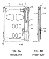
- a card connector 11 As illustrated in Figs. 1A and 1B, a card connector 11 according to Reference Document 1 comprises a housing 13 and a cover 15 covering it. At one side in the housing 13, an L-shaped ejecting bar 17 is provided and biased by a coil spring 19 toward the front end of the connector 11 as indicated by an arrow 27. A projecting portion of the L-shaped ejecting bar 17 is adapted to engage with an insertion-side end of a card 21 so that the ejecting bar 17 moves toward the rear end of the connector 11 following the insertion of the card 21.
- the cover 15 is provided with a brake 23 that is formed by cutting so as to be inclined toward the inside of the connector 11.
- a heart-cam mechanism (not illustrated) causes the ejecting bar 17 to alternately repeat a locked state where the ejecting bar 17 is stopped at the rear end against a biasing force of the coil spring 19 and an unlocked state where the ejecting bar 17 is moved forward by the biasing force of the coil spring 19.
- the brake 23 has elasticity and is pushed up outward by the card 21 upon insertion thereof so as to be in constant sliding contact with one surface of the card 21.
- the brake 23 continues to apply a frictional force to the card 21 as indicated by an arrow 25 while slidingly contacting the card 21, to thereby prevent the card 21 from leaping out of the connector 11.
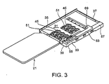
- a card connector 29 has the W-Push function that alternately repeats loading and ejection of a card 21 in the form of an IC card every time the card is pushed.
- the connector 29 comprises a housing 39 and a cover frame 41.
- the housing 39 has a bottom portion 31, side walls 33 and 35, and a rear wall 37 that form a rectangular box-like shape having a " ] "-shape in cross section.
- the cover frame 41 has a " ] "-shape in cross section and covers the housing 39.
- a box formed by the housing 39 and the cover frame 41 has a front end where an opening 43 is formed for insertion and removal of the card 21 therethrough.
- the card insertion direction shall be defined as a first direction and, in this first direction, the end of the connector 29 where the opening 43 is formed shall be defined as a front end and its opposite end as a rear end. Further, the width direction of the connector 29 shall be defined as a second direction and its height direction as a third direction, wherein the first, second, and third directions are set perpendicular to each other.
- the connector 29 further comprises contacts 51 for electrical connection to the card 21.
- the contacts 51 are provided at the bottom portion 31 of the housing 39 such that contact portions 47 thereof protrude from rectangular mounting holes 45 arrayed in two rows in the second direction.
- the housing 39 further serves as a guide for the card 21 and an ejecting bar 53.
- the connector 29 further comprises, on an inner side of the side wall 33 of the housing 39, the ejecting bar 53 extending in the first direction along an inner surface of the side wall 33, a brake 55 engaging with the ejecting bar 53, and a coil spring 57 biasing the ejecting bar 53 in the first direction toward the front end from the rear end.
- the ejecting bar 53 is formed with a heart-cam groove 59 at a portion thereof where a base portion of the brake 55 is fixedly received.
- the heart-cam groove 59 constitutes part of the heart-cam mechanism.
- the heart-cam mechanism further comprises a cam follower 63 provided between the ejecting bar 53 and the side wall 33 of the housing 39.
- the cam follower 63 has an inward projecting tip end portion 61 that is inserted into the heart-cam groove 59 on the side of the ejecting bar 53.
- the cam follower 63 further has at its rear end a hole 67 receiving therein a pin 65 projecting into the inside of the housing 39 through the side wall 33 so that the cam follower 63 is rotatable about the pin 65.
- a card ejecting mechanism comprises the ejecting bar 53, the brake 55, the coil spring 57, and the heart-cam mechanism.
- numeral 73 denotes a lateral end of the ejecting bar 53
- numeral 75 denotes a guide groove of the ejecting bar 53.
- the ejecting bar 53 is formed into an L-shape so as to have at its rear end a projection 69 that is adapted to engage with an insertion-side end of the card 21.
- the card 21 is ejected by a biasing force of the coil spring 57 exerted on the ejecting bar 53 that is in direct contact with the card 21.
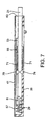
- the brake 55 comprises a pair of springs (contact pieces) 71 as a card retaining portion for sandwiching the card 21 under pressure from upper and lower sides in the figures.
- the brake 55 is fixed to the ejecting bar 53 and thus moves together with the ejecting bar 53 upon insertion and ejection of the card 21. This allows the card 21 to be prevented from leaping out of the connector 29 when the card 21 is ejected.
- the pair of springs 71 have such elastic forces that the springs cause abrasion forces with clipping the card 21 equally from both sides, the card 21 can be clipped to be prevented from leaping out of the connector 29 when inserting or ejecting the card but can not be prevented from ejecting.
- the contact pieces 71, arranged in a " ⁇ " -shape, of the brake 55 are pushed open to thereby sandwich the card 21 therebetween under pressure as illustrated in Fig. 7. More specifically, as illustrated in Fig.
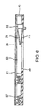
- the ejecting bar 53 is unlocked by the heart-cam mechanism so that the ejecting bar 53 along with the card 21 is moved by the biasing force of the coil spring 57 toward the front end as indicated by an arrow 81. Because of being fixed to the ejecting bar 53, the brake 55 moves together with the ejecting bar 53 while sandwiching the card 21 under pressure even during the ejection of the card 21.
- the braking force of the brake 55 does not serve as a frictional force against the biasing force of the coil spring 57 to eject the card 21 via the ejecting bar 53, it is possible to increase the braking force while, at the same time, preventing occurrence of stoppage of the card 21 on the way of its ejection. Further, since the card 21 is constantly sandwiched under pressure, it is possible to prevent the leaping-out of the card 21 during the ejection. Consequently, the ejection of the card 21 can be achieved with high reliability.
- the card ejecting mechanism is configured to eject the card 21 by the use of the coil spring 57, which is different from the conventional mechanism of ejecting the card via the lever by pushing the button. Therefore, the ejecting bar 53 is prevented from stopping on the way of ejection of the card 21.
- the brake 55 is fixed to the ejecting bar 53 itself serving to eject the card 21, and the card 21 is retained by the brake 55 itself. Therefore, the retaining force of the brake 55 does not function as the frictional force against the force to eject the card 21 so that it is possible to prevent occurrence of ejection failure wherein the card 21 stops on the way of its ejection.
- the brake springs 23 are formed inside the case so that the card is often leaped out from the case or stopped on the way of ejecting the card 21.
- the brake springs 71 are formed at ejecting bar 53 so that the card 21 can not be leaped out from the case or can not be stopped on the way of ejecting the card 21.
- the card connector according to this invention has high reliability and is applicable to card slots of personal computers, and card connectors of portable mobile terminals, various digital devices, and various electrical and electronic devices.
Landscapes
- Physics & Mathematics (AREA)
- General Physics & Mathematics (AREA)
- Engineering & Computer Science (AREA)
- Theoretical Computer Science (AREA)
- Coupling Device And Connection With Printed Circuit (AREA)
- Details Of Connecting Devices For Male And Female Coupling (AREA)
Applications Claiming Priority (2)
| Application Number | Priority Date | Filing Date | Title |
|---|---|---|---|
| JP2003433079A JP3841353B2 (ja) | 2003-12-26 | 2003-12-26 | カード用コネクタ |
| JP2003433079 | 2003-12-26 |
Publications (2)
| Publication Number | Publication Date |
|---|---|
| EP1548897A1 true EP1548897A1 (de) | 2005-06-29 |
| EP1548897B1 EP1548897B1 (de) | 2006-11-08 |
Family
ID=34545071
Family Applications (1)
| Application Number | Title | Priority Date | Filing Date |
|---|---|---|---|
| EP04030632A Expired - Lifetime EP1548897B1 (de) | 2003-12-26 | 2004-12-23 | Kartenverbinder, der sowohl Herausfallen als auch Auswurffehler einer Karte vermeiden kann. |
Country Status (7)
| Country | Link |
|---|---|
| US (1) | US7070429B2 (de) |
| EP (1) | EP1548897B1 (de) |
| JP (1) | JP3841353B2 (de) |
| KR (1) | KR100679441B1 (de) |
| CN (1) | CN1312810C (de) |
| DE (1) | DE602004003118T2 (de) |
| TW (1) | TWI251964B (de) |
Families Citing this family (11)
| Publication number | Priority date | Publication date | Assignee | Title |
|---|---|---|---|---|
| JP4746488B2 (ja) * | 2006-06-23 | 2011-08-10 | 山一電機株式会社 | Icカード用コネクタ |
| JP2008053124A (ja) | 2006-08-25 | 2008-03-06 | Jst Mfg Co Ltd | カード用コネクタ |
| JP4829074B2 (ja) * | 2006-11-01 | 2011-11-30 | 富士通コンポーネント株式会社 | カードコネクタ |
| JP4582214B2 (ja) * | 2008-06-30 | 2010-11-17 | ミツミ電機株式会社 | コネクタ |
| CN201430265Y (zh) * | 2009-04-17 | 2010-03-24 | 富士康(昆山)电脑接插件有限公司 | 电子卡连接器 |
| JP1552812S (de) * | 2015-11-03 | 2016-06-27 | ||
| JP1553611S (de) * | 2015-11-03 | 2016-07-11 | ||
| JP1553879S (de) * | 2015-11-03 | 2016-07-11 | ||
| JP1552813S (de) * | 2015-11-04 | 2016-06-27 | ||
| JP1552814S (de) * | 2015-11-04 | 2016-06-27 | ||
| JP1552815S (de) * | 2015-11-06 | 2016-06-27 |
Citations (1)
| Publication number | Priority date | Publication date | Assignee | Title |
|---|---|---|---|---|
| US20010055896A1 (en) * | 2000-04-12 | 2001-12-27 | Toshihumi Takada | Card connector |
Family Cites Families (13)
| Publication number | Priority date | Publication date | Assignee | Title |
|---|---|---|---|---|
| JPH0566768U (ja) | 1992-02-21 | 1993-09-03 | スズキ株式会社 | メモリーカード脱落防止装置 |
| JP2568489Y2 (ja) | 1992-09-30 | 1998-04-15 | 第一電子工業株式会社 | 電子カード用コネクタ装置 |
| JP2597283Y2 (ja) | 1993-09-22 | 1999-07-05 | 日本航空電子工業株式会社 | 離脱機構付きコネクタ |
| JPH1153486A (ja) | 1997-08-06 | 1999-02-26 | Sharp Corp | カードロック機構 |
| JP3483454B2 (ja) * | 1998-02-05 | 2004-01-06 | アルプス電気株式会社 | Icカード用コネクタ装置 |
| JP4365977B2 (ja) * | 2000-03-10 | 2009-11-18 | モレックス インコーポレイテド | カード用コネクタ |
| JP3383917B2 (ja) | 2000-03-16 | 2003-03-10 | 日本航空電子工業株式会社 | プッシュ−プッシュ式カード用コネクタ |
| WO2002007269A2 (en) * | 2000-06-29 | 2002-01-24 | Molex Incorporated | Ic card connector |
| JP3429266B2 (ja) * | 2000-10-19 | 2003-07-22 | 山一電機株式会社 | カードコネクタ |
| JP2003297484A (ja) * | 2001-11-19 | 2003-10-17 | Yamaichi Electronics Co Ltd | カードコネクタ |
| JP4028231B2 (ja) * | 2001-12-28 | 2007-12-26 | 日本圧着端子製造株式会社 | カード用コネクタのエジェクト機構 |
| TW536020U (en) * | 2002-05-23 | 2003-06-01 | Molex Inc | Card ejecting mechanism of electronic card connector |
| JP3876194B2 (ja) * | 2002-07-03 | 2007-01-31 | アルプス電気株式会社 | カード用コネクタ装置 |
-
2003
- 2003-12-26 JP JP2003433079A patent/JP3841353B2/ja not_active Expired - Fee Related
-
2004
- 2004-12-22 US US11/020,455 patent/US7070429B2/en not_active Expired - Fee Related
- 2004-12-23 DE DE602004003118T patent/DE602004003118T2/de not_active Expired - Lifetime
- 2004-12-23 TW TW093140172A patent/TWI251964B/zh not_active IP Right Cessation
- 2004-12-23 CN CNB2004101037264A patent/CN1312810C/zh not_active Expired - Fee Related
- 2004-12-23 EP EP04030632A patent/EP1548897B1/de not_active Expired - Lifetime
- 2004-12-24 KR KR1020040111757A patent/KR100679441B1/ko not_active Expired - Fee Related
Patent Citations (1)
| Publication number | Priority date | Publication date | Assignee | Title |
|---|---|---|---|---|
| US20010055896A1 (en) * | 2000-04-12 | 2001-12-27 | Toshihumi Takada | Card connector |
Also Published As
| Publication number | Publication date |
|---|---|
| TW200533016A (en) | 2005-10-01 |
| KR100679441B1 (ko) | 2007-02-06 |
| DE602004003118T2 (de) | 2007-02-15 |
| EP1548897B1 (de) | 2006-11-08 |
| CN1312810C (zh) | 2007-04-25 |
| JP2005190908A (ja) | 2005-07-14 |
| JP3841353B2 (ja) | 2006-11-01 |
| DE602004003118D1 (de) | 2006-12-21 |
| CN1638206A (zh) | 2005-07-13 |
| KR20050067045A (ko) | 2005-06-30 |
| US7070429B2 (en) | 2006-07-04 |
| US20050142914A1 (en) | 2005-06-30 |
| TWI251964B (en) | 2006-03-21 |
Similar Documents
| Publication | Publication Date | Title |
|---|---|---|
| US6609919B2 (en) | Card connector | |
| US6976879B2 (en) | Card connector | |
| CN102422491B (zh) | 卡连接器 | |
| JP3876194B2 (ja) | カード用コネクタ装置 | |
| US7238034B2 (en) | Memory card connector | |
| JP2003178846A (ja) | カードコネクタ | |
| JPH1154207A (ja) | カードコネクタ | |
| US7070429B2 (en) | Card connector that can prevent both leaping-out and ejection failure of a card | |
| US6059589A (en) | Connector device for IC card | |
| US6520783B2 (en) | Electrical card connector having polarization mechanism | |
| KR101110383B1 (ko) | 카드용 커넥터 | |
| US7708575B2 (en) | Card connector capable of switching a card holding state with a simple structure | |
| CN107636912B (zh) | 卡连接器 | |
| EP1556926B1 (de) | Speicherkartenverbinder | |
| US7198498B2 (en) | Card connector | |
| US7300295B2 (en) | Connector which can be reduced in operating force and miniaturized | |
| US7448886B2 (en) | Card connector with anti-mismating device | |
| JP3450995B2 (ja) | Icカード用コネクタ装置 | |
| GB2251134A (en) | Ejector-equipped card connector | |
| KR20050088140A (ko) | 가동 커넥터 | |
| JP3945432B2 (ja) | メモリカード用ソケット | |
| CN100492776C (zh) | 卡用连接装置 | |
| US7320612B2 (en) | Card connector | |
| JP2006100210A (ja) | メモリーカード用コネクタ | |
| JP2005347219A (ja) | カードコネクタ |
Legal Events
| Date | Code | Title | Description |
|---|---|---|---|
| PUAI | Public reference made under article 153(3) epc to a published international application that has entered the european phase |
Free format text: ORIGINAL CODE: 0009012 |
|
| 17P | Request for examination filed |
Effective date: 20050427 |
|
| AK | Designated contracting states |
Kind code of ref document: A1 Designated state(s): AT BE BG CH CY CZ DE DK EE ES FI FR GB GR HU IE IS IT LI LT LU MC NL PL PT RO SE SI SK TR |
|
| AX | Request for extension of the european patent |
Extension state: AL BA HR LV MK YU |
|
| AKX | Designation fees paid |
Designated state(s): DE FI FR GB |
|
| GRAP | Despatch of communication of intention to grant a patent |
Free format text: ORIGINAL CODE: EPIDOSNIGR1 |
|
| GRAS | Grant fee paid |
Free format text: ORIGINAL CODE: EPIDOSNIGR3 |
|
| GRAA | (expected) grant |
Free format text: ORIGINAL CODE: 0009210 |
|
| RIN1 | Information on inventor provided before grant (corrected) |
Inventor name: SUZUKI, KEIICHIRO Inventor name: MOTOJIMA, JOE Inventor name: KODERA, MASAFUMI Inventor name: NATORI, AKIRA |
|
| AK | Designated contracting states |
Kind code of ref document: B1 Designated state(s): DE FI FR GB |
|
| REG | Reference to a national code |
Ref country code: GB Ref legal event code: FG4D |
|
| REF | Corresponds to: |
Ref document number: 602004003118 Country of ref document: DE Date of ref document: 20061221 Kind code of ref document: P |
|
| ET | Fr: translation filed | ||
| PLBE | No opposition filed within time limit |
Free format text: ORIGINAL CODE: 0009261 |
|
| STAA | Information on the status of an ep patent application or granted ep patent |
Free format text: STATUS: NO OPPOSITION FILED WITHIN TIME LIMIT |
|
| 26N | No opposition filed |
Effective date: 20070809 |
|
| PGFP | Annual fee paid to national office [announced via postgrant information from national office to epo] |
Ref country code: DE Payment date: 20141216 Year of fee payment: 11 Ref country code: GB Payment date: 20141217 Year of fee payment: 11 Ref country code: FI Payment date: 20141209 Year of fee payment: 11 |
|
| REG | Reference to a national code |
Ref country code: FR Ref legal event code: PLFP Year of fee payment: 12 |
|
| PGFP | Annual fee paid to national office [announced via postgrant information from national office to epo] |
Ref country code: FR Payment date: 20151110 Year of fee payment: 12 |
|
| REG | Reference to a national code |
Ref country code: DE Ref legal event code: R119 Ref document number: 602004003118 Country of ref document: DE |
|
| GBPC | Gb: european patent ceased through non-payment of renewal fee |
Effective date: 20151223 |
|
| PG25 | Lapsed in a contracting state [announced via postgrant information from national office to epo] |
Ref country code: DE Free format text: LAPSE BECAUSE OF NON-PAYMENT OF DUE FEES Effective date: 20160701 Ref country code: GB Free format text: LAPSE BECAUSE OF NON-PAYMENT OF DUE FEES Effective date: 20151223 |
|
| PG25 | Lapsed in a contracting state [announced via postgrant information from national office to epo] |
Ref country code: FI Free format text: LAPSE BECAUSE OF NON-PAYMENT OF DUE FEES Effective date: 20151223 |
|
| REG | Reference to a national code |
Ref country code: FR Ref legal event code: ST Effective date: 20170831 |
|
| PG25 | Lapsed in a contracting state [announced via postgrant information from national office to epo] |
Ref country code: FR Free format text: LAPSE BECAUSE OF NON-PAYMENT OF DUE FEES Effective date: 20170102 |