EP1548560A2 - Speichersystem mit einer Funktion zur dynamischen Volumenzuordnung - Google Patents
Speichersystem mit einer Funktion zur dynamischen Volumenzuordnung Download PDFInfo
- Publication number
- EP1548560A2 EP1548560A2 EP04027413A EP04027413A EP1548560A2 EP 1548560 A2 EP1548560 A2 EP 1548560A2 EP 04027413 A EP04027413 A EP 04027413A EP 04027413 A EP04027413 A EP 04027413A EP 1548560 A2 EP1548560 A2 EP 1548560A2
- Authority
- EP
- European Patent Office
- Prior art keywords
- command
- storage system
- target device
- ldev
- computer
- Prior art date
- Legal status (The legal status is an assumption and is not a legal conclusion. Google has not performed a legal analysis and makes no representation as to the accuracy of the status listed.)
- Withdrawn
Links
Images








Classifications
-
- G—PHYSICS
- G06—COMPUTING OR CALCULATING; COUNTING
- G06F—ELECTRIC DIGITAL DATA PROCESSING
- G06F3/00—Input arrangements for transferring data to be processed into a form capable of being handled by the computer; Output arrangements for transferring data from processing unit to output unit, e.g. interface arrangements
- G06F3/06—Digital input from, or digital output to, record carriers, e.g. RAID, emulated record carriers or networked record carriers
- G06F3/0601—Interfaces specially adapted for storage systems
- G06F3/0628—Interfaces specially adapted for storage systems making use of a particular technique
- G06F3/0629—Configuration or reconfiguration of storage systems
- G06F3/0631—Configuration or reconfiguration of storage systems by allocating resources to storage systems
-
- G—PHYSICS
- G06—COMPUTING OR CALCULATING; COUNTING
- G06F—ELECTRIC DIGITAL DATA PROCESSING
- G06F3/00—Input arrangements for transferring data to be processed into a form capable of being handled by the computer; Output arrangements for transferring data from processing unit to output unit, e.g. interface arrangements
- G06F3/06—Digital input from, or digital output to, record carriers, e.g. RAID, emulated record carriers or networked record carriers
- G06F3/0601—Interfaces specially adapted for storage systems
- G06F3/0602—Interfaces specially adapted for storage systems specifically adapted to achieve a particular effect
- G06F3/0604—Improving or facilitating administration, e.g. storage management
- G06F3/0605—Improving or facilitating administration, e.g. storage management by facilitating the interaction with a user or administrator
-
- G—PHYSICS
- G06—COMPUTING OR CALCULATING; COUNTING
- G06F—ELECTRIC DIGITAL DATA PROCESSING
- G06F3/00—Input arrangements for transferring data to be processed into a form capable of being handled by the computer; Output arrangements for transferring data from processing unit to output unit, e.g. interface arrangements
- G06F3/06—Digital input from, or digital output to, record carriers, e.g. RAID, emulated record carriers or networked record carriers
- G06F3/0601—Interfaces specially adapted for storage systems
- G06F3/0668—Interfaces specially adapted for storage systems adopting a particular infrastructure
- G06F3/0671—In-line storage system
- G06F3/0683—Plurality of storage devices
-
- Y—GENERAL TAGGING OF NEW TECHNOLOGICAL DEVELOPMENTS; GENERAL TAGGING OF CROSS-SECTIONAL TECHNOLOGIES SPANNING OVER SEVERAL SECTIONS OF THE IPC; TECHNICAL SUBJECTS COVERED BY FORMER USPC CROSS-REFERENCE ART COLLECTIONS [XRACs] AND DIGESTS
- Y10—TECHNICAL SUBJECTS COVERED BY FORMER USPC
- Y10S—TECHNICAL SUBJECTS COVERED BY FORMER USPC CROSS-REFERENCE ART COLLECTIONS [XRACs] AND DIGESTS
- Y10S707/00—Data processing: database and file management or data structures
- Y10S707/99951—File or database maintenance
- Y10S707/99952—Coherency, e.g. same view to multiple users
- Y10S707/99953—Recoverability
-
- Y—GENERAL TAGGING OF NEW TECHNOLOGICAL DEVELOPMENTS; GENERAL TAGGING OF CROSS-SECTIONAL TECHNOLOGIES SPANNING OVER SEVERAL SECTIONS OF THE IPC; TECHNICAL SUBJECTS COVERED BY FORMER USPC CROSS-REFERENCE ART COLLECTIONS [XRACs] AND DIGESTS
- Y10—TECHNICAL SUBJECTS COVERED BY FORMER USPC
- Y10S—TECHNICAL SUBJECTS COVERED BY FORMER USPC CROSS-REFERENCE ART COLLECTIONS [XRACs] AND DIGESTS
- Y10S707/00—Data processing: database and file management or data structures
- Y10S707/99951—File or database maintenance
- Y10S707/99952—Coherency, e.g. same view to multiple users
- Y10S707/99955—Archiving or backup
Definitions
- the present invention relates to a storage system for storing data used by a computer.
- a device that is specified by a port ID and a LUN, and recognized as a subject of access from a host computer will be referred to as a target device.
- the juke box system may change the logical device allocated to the target device in accordance with a command from the computer to a command device, which is one of the plural target devices.
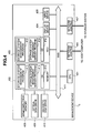
- This system comprises one or more host computers 1, one or more storage systems 2, and one or more management devices 3.
- the host computer 1 and storage system 2 are connected by a first communication path 12, enabling the host computer 1 to perform data input/output processing to and from the storage system 2 via the first communication path 12.
- the host computer 1 and management device 3 are connected by a second communication path 13, and the management device 3 and storage system 2 are also connected by the second communication path 13.
- the host computer 1 is able to perform setting processing on the storage system 2 remotely through the second communication path 13 and management device 3.
- a conceivable example of a case in which the storage system 2 uses the juke box function in accordance with a request from the AP 17 is when the AP 17 is electronic mail software, for example, and received mail is classified into months and stored inseparateLDEVs. ToreadmailreceivedinNovember, for example, the AP 17 accesses the LDEV storing mail data for November. Then, when the AP 17 wishes to access mail received in December, the AP 17 must allocate the LDEV storing mail data for December to the target device in place of the LDEV storing the mail data for November.
- the host computer 1 comprises a CPU (central processing unit) 301, memory 302, a hard disk drive (HDD) 303, a display device 304, an input device 305, an input/output device adapter 307, and a network adapter 306. A plurality of each of these components maybe provided.
- the host computer 1 may also comprise a semiconductor memory drive 308, an optical disk drive 309, a magnetic disk drive 310, and so on.
- the management device 3 shown in Fig. 1 comprises a storage system management mechanism 10 and a storage system management server 11.
- a program stored in memory provided in the management device 3 is executed by a control processor provided in the management device 3.
- Fig. 6 is a view showing an example of the juke box information 217.
- the juke box information 1005 is a pointer for pointing to the juke box information 217 relating to the LDEV.
- the storage system management program 413 Having received the configuration information (step 504), the storage system management program 413 outputs the received configuration information to the display device 404, or transmits the configuration information to the host computer 1 used by the user via the storage system management server program 414 and second communication path 13.
- the configuration control program 210 Having received the configuration information update command (step 507), the configuration control program 210 transmits a configuration information update preparation completion response indicating reception of this command to the storage system management program 413 (step 508).
- the storage system management program 413 Having received the response (step509), the storage system management program 413 transmits the definition information created in step 505 to the configuration control program 210 via the second communication path 13 (step 510).
- the configuration control program 210 updates the configuration information according to the received definition information, thereby defining the LDEV indicated by the LDEV number specified by the storage system management program 413 as the juke box system 6. More specifically, information indicating a juke box system is stored in the condition 1001 of the LDEV information 216 for the LDEV number specified by the definition information, and the identification information (port ID (WWN) and internal LUN) of the target device used as the command device is stored in the path definition information. Further, the configuration control program 210 updates the target device-LDEV mapping information 214 on the basis of the received definition information, and relates the command device to the LDEV specified by the definition information. The configuration control program 210 also updates the juke box information 217 relating to the LDEV and command device specified by the definition information. The configuration control program 210 then transmits a configuration information update completion report to the storage system management program 413 (step 512).
- the storage system management program 413 Having received the configuration information update completion report (step 513), the storage system management program 413 outputs an update completion report to the user, whereupon a state of standby is entered to await confirmation of the end of processing.
- the storage system management program 413 ends the processing (step 514).
- Fig. 9 is a view showing an example of a processing procedure implemented when acquiring the configuration information 218 of the storage system 2 from the host computer 1.
- the storage systemmanager program 313 Having received the response relating to the configuration information acquisition request command (step 607) , the storage systemmanager program 313 transmits a configuration information acquisition command to the juke box system 6 (step 608).
- the configuration control program 210 prepares the configuration information for transmission to the command control program 210 (step 605) .
- the configuration control program 210 prepares the LDEV information 216 for the LDEVs that can be allocated to the target devices corresponding to the content of the host computer target device list 219(a) for the host computer 1 which issued the configuration information acquisition request command, and the set comprising the WWN and LUN recorded in this host computer target device list 219 (a) , and the juke box information 217 relating to these target devices. This information may be obtained by referring to the access-permitted host list 219, the juke box information 217, and the LDEV information 216.
- the configuration control program 210 Having received the configuration information acquisition request (step 611), the configuration control program 210 informs the command control program 208 of the memory address at which the configuration information prepared in step 605 is stored and the size of the prepared configuration information, and transmits a configuration information preparation completion report to the command control program (step 612).
- the command control program 208 Having received the configuration information preparation completion report from the configuration control program 210 (step 613), the command control program 208 reads the configuration information from the memory region indicated by the memory address notified by the configuration control program 210, and transmits the configuration information to the host computer 1 (step 614).
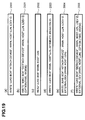
- Fig. 19 is a view showing examples of commands issued by the host computer 1 to the storage system 2. Note that identification information identifying the host computer 1 (for example, the WWN of the host computer 1), which is the source of the command, is included in the commands shown in Fig. 19, although not illustrated in Fig. 19 itself.
- the various commands issued by the host computer 1 to the juke box system (command device) take a read command or write command format to or from the command device, as shown in Fig. 19.
- identification information for the target device neednot be included inthe configuration informationacquisition request command 2002.
- a list of the target devices that can be accessed from the host computer which is the issuing source of the configuration information acquisition request command 2002, the juke box information 217 relating to each of the target devices included in the list, and the LDEV information 216 of the LDEVs that can be allocated to each of the target devices is prepared by the configuration control program 210.
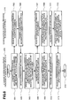
- Fig. 10 is a view showing an example of detachment processing for detaching a path definition to a target device by disengaging the LDEV allocation to the target device.
- the host computer 1 uses the configuration information 218 obtained through the processing shown in Fig. 9, which was performed using the storage system manager program 313, to perform processing to substitute the LDEV allocated to a target device using the juke box system manager program 314.
- Fig. 1 illustrates this example.
- the juke box system 6 of the storage system 2 substitutes the first LDEV 8 allocated to the target device 7 for the second LDEV 9.
- LDEV detachment (disengagement) processing will be described using an example of processing to disengage the first LDEV from the target device to which it is allocated.
- This write command is received by the command control program 208 of the storage system 2, whereupon write processing is executed by the disk I/O program 212 (not shown in the drawing) .
- the juke box system manager program 314 transmits to the juke box system 6 (or in other words the command device) a read only attribute assignment command requesting that from now on, only read processing be permitted on the first LDEV to be substituted (step 702).
- the juke box system manager program 314 transmits a port ID (WWN) and host LUN to the juke box system 6 to specify the target device to which the first LDEV, which is the object of read only attribute assignment, is allocated.
- WWN port ID
- the command control program 208 interprets the received command, and specifies the identification number of the first LDEV which is the object of read only attribute assignment by referring to the access-permitted host list 219 and the target device-LDEV mapping information 214 .
- the command control program 208 then instructs the configuration control program 210 to assign a read only attribute to the specified first LDEV (step 704).
- the configuration control program 210 updates the attribute 1008 of the LDEV information 216 corresponding to the LDEV number to a read only attribute (step 705).
- the configuration control program 210 then transmits notification of the completion of read only attribute assignment to the command control program 208 (step 706).
- the juke box system manager program 314 in the host computer transmits an LDEV detach command to the juke box system 6.
- the detach command specifies a port ID (WWN) and host LUN serving as the identifiers of the target device to which the first LDEV to be substituted is allocated (step 710).
- the command control program 208 interprets the command and transmits a detachment request to the path control program 209 (step 711).
- the path control program 209 uses the access-permitted host list 219 to specify the port ID (WWN) and internal LUN of the target device which is the subject of the detachment request (step 712).
- the path control program 209 then checks whether the specified target device is implemented, whether the target device is faulty, whether the host computer 1 which transmitted the detach command is authorized to access the target device, and so on. This information can be confirmed by referring to the target device-LDEV mapping information 214, the access-permitted host list 219, and so on in the configuration information 218.
- the path control program 209 performs path definition detachment. More specifically, the path control program 209 creates definition information to be notified to the configuration control program 210 in order to disengage the first LDEV from the target device. The path control program 209 then notifies the configuration control program 210 of the path definition modification and the created definition information (step 713).
- the configuration controlprogram210 deletes the target device-LDEV mapping information 214 relating the target device to the detached first LDEV on the basis of the definition information.
- the configuration control program 210 also updates the LDEV information 216 of the first LDEV, and registers a null in the path definition 1002.
- the configuration control program 210 also updates the juke box information 217, registers the current time in the latest access path detachment time 1205, and registers the time that is registered in the path definition time 1202 in the latest access path definition time 1204.
- the configuration control program 210 then transmits a completion report to the path control program 209 (step 715).
- the path control program 209 transmits an LDEV detachment completion response to the command control program 208 (step 716). Having detected the detachment completion response, the command control program 208 transmits a detachment completion response corresponding to the detach command received in step 710 to the host computer 1 (step 717) .
- the juke box system manager program 314 Having received the detachment completion response (step 718), the juke box system manager program 314 outputs completion information to the display device 304, and then ends detachment processing.
- the reason for changing the attribute of the first LDEV that is disengaged from the target device to a read only attribute from step 702 to step 709 is that depending on the AP 17 operating on the host computer 1, there may be a desire to change the data in the LDEV that is disengaged from the target device after the end of writing processing to a WORM (write once read many) format to ensure that the data are not manipulated.
- the AP 17 is mail software
- the LDEV storing the mail data for November may be disengaged from the target device and a new LDEV for storing mail data for December may be allocated to the target device.
- the mail data for November can be protected from further manipulation.
- a read only attribute be assigned to the LDEV prior to detachment processing. If, on the other hand, there is a possibility that rewriting processing will be executed on the LDEV that is disengaged from the target device following writing processing in the future, the processing of steps 702 through 709 may be omitted.
- the LDEV is disengaged from the target device when the detach command is issued from the host computer 1, but the storage system 2 may begin the processing of steps 704 through 707 and steps 711 through 717 automatically when the time recorded in the path detachment time 1203 of the juke box information 217 is reached.
- Fig. 19D is a view showing an example of a read only attribute assignment command 2003 issued from the juke box system manager program 314 in step 702.
- the read only attribute assignment command 2003 comprises "JUKE BOX", identifying the juke box system (command device) of the command destination, a port ID (WWN) and host LUN specifying the target device to which the first LDEV, which is to be assigned with the read only attribute, is allocated (path-defined), and the information "Attribute (Read Only)" indicating that a read only attribute is to be assigned.
- the read only attribute assignment command 2003 takes a write command format.
- Fig. 19B is a view showing an example of a detach command 2001 issued from the juke box system manager program 314 in step 710.
- the detach command 2001 comprises "JUKE BOX", identifying the juke box system of the command destination, "Detach Device” indicating that the command is a detach command, a set of a port ID (WWN) and host LUN serving as the identification information of the target device to which the LDEV to be detached is path-defined, the LDEV number of the first LDEV to be detached, information indicating that the detachment subject first LDEV may be changed to a WORM format as an option, and information indicating the time period of the WORM format. Note that as long as the target device subject to detachment can be specified, the LDEV number of the LDEV to be detached need not be included in the detach command.
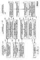
- Fig. 11 is a view showing an example of attachment processing for setting a path definition to a target device by allocating a new LDEV to the target device.
- LDEV attachment processing will be described using an example in which, following the processing shown in Fig. 10, the juke box function is used to newly allocate the second LDEV to a target device.
- the juke box system manager program 314 transmits to the juke box system 6 (or in other words the command device) of the storage system 2 a command (also referred to as "attach command” hereafter) indicating that the second LDEV is to be newly allocated to a target device (step 801).
- the attach command comprises identification information (i.e. a port ID (WWN) and host LUN) for the target device that is the subject of the attach command, and the LDEV number of the second LDEV to be newly allocated to the target device.
- the command control program 208 analyzes the command to determine that the command relates to input/output processing on the juke box system 6 and that the content of the command is an attachment request to allocate the second LDEV to the target device, and then transmits an attachment request to the path control program 209 requesting that the second LDEV be path-defined to the target device (step 803).
- the path control program 209 specifies the identifiers (i.e. the port ID (WWN) and internal LUN) of the target device that is the subject of the received attachment request on the basis of the attachment request (step 804). This processing may be performed by referring to the access-permitted host list 219.
- the path control program 209 also checks whether an LDEV is path defined to the specified target device. This processing maybe performed by referring to the configuration information 218, and in particular the target device-LDEV mapping information 214.
- the path control program 209 checks the second LDEV to be allocated to the target device (step 805). More specifically, the path control program 209 confirms that the LDEV is normal (not faulty) , the LDEV is not allocated to other processing, the LDEV is not reserved for other processing, the LDEV is not path defined, the LDEV has not been allocated to the target device by the juke box system up to the present, and so on. This information can be confirmed by referring to the condition 1001, program usage information 1003, program reservation information 1004, and path definition 1002 in the LDEV information 216 of the second LDEV, and the latest access path definition time 1204 in the juke box information 217.
- the path control program 209 allocates the second LDEV to the target device specified by the attach command, and path-defines the second LDEV to the target device.
- the path control program 209 creates definition information for allocating the second LDEV to the target device.
- the path control program 209 then transmits notification of the new path definition to the configuration control program 210 together with the definition information (step 806).
- the configuration control program 210 rewrites the target device-LDEV mapping information 214 on the basis of the received definition information such that the second LDEV is allocated to the target device that is the subject of attachment.
- the configuration control program 210 also modifies the LDEV information 216 relating to the second LDEV, and records the port ID (WWN) and internal LUN serving as the identification information of the target device to which the second LDEV is allocated in the path definition 1002. Further, the configuration control program 210 updates the juke box information 217, and records the current time in the path definition time 1202 and the estimated disengagement time of this path setting in the path detachment time (step 808).
- the configuration control program 210 then notifies the path control program 209 that update processing of the configuration information 218 is complete, and upon reception of this notification, the path control program 209 transmits an attachment completion response to the command control program 208 (step 809).
- the command control program 208 transmits to the host computer 1 an attachment processing completion response which serves as a response to the attach command received in step 802 (step 810).
- the juke box system manager program 314 reacknowledges the target device, and if the capacity of the device has changed, detects this change and confirms the capacity of the new second LDEV (step 812).
- the juke box system manager program 314 then allows I/O processing to recommence on the target device, writes the identification information of the target device, the identification information of the host computer 1 (or the juke box system manager 5), and the date and time at which the path definition was set in a specific region of the newly allocated LDEV (step 813), and then ends the processing.
- attachment processing can be performed to allocate the new second LDEV to the target device.
- the host computer 1 places an access request (a read or write request) for access to the target device to which the second LDEV is newly path defined after the end of this attachment processing
- the storage system 2 executes access processing on the second LDEV on the basis of the updated target device-LDEV mapping information 214.
- Fig. 19A is a view showing an example of an attach command 2000 issued in step 801.
- the attach command 2000 comprises "JUKE BOX” indicating the destination of the command, "Attach Device” indicating that the command is an attach command, a set of the WWN and host LUN serving as the identification information of the target device that is subject to attachment, and an LDEV number for identifying the LDEV to be attached.
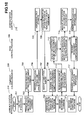
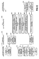
- Fig. 12 shows an example of processing to reattach an LDEV to a target device after being path defined to the target device in the past and then detached therefrom.
- attachment processing shown in Fig. 11 is performed to allocate a new LDEV to a target device
- reattachment processing shown in Fig. 12 is performed to reattach an LDEV to a target device after having been allocated to the target device once in the past and then disengaged therefrom.
- the host computer 1 first issues a detach command relating to the first LDEV, then executes detachment processing on the storage system 2, then issues an attach command relating to the second LDEV, and then executes attachment processing on the storage system 2.
- detachment processing for the first LDEV and attachment processing for the second LDEV are executed in the storage system 2 simply by having the host computer 1 issue a single attach command for the second LDEV.
- detachment processing and attachment processing may be executed in the storage system 2 as a series of processes based on a single attach command regardless of whether the LDEV to be attached is a new LDEV or an LDEV that has been attached to a target device once before.
- the juke box system manager program 314 transmits to the juke box system 6 (or in other words the command device) an attach command specifying a port ID (WWN) and host LUN set serving as the identification information of the target device subject to processing, and an LDEV number serving as the identification number of the LDEV to be reattached to the target device (step 901).
- WWN port ID
- LDEV number serving as the identification number of the LDEV to be reattached to the target device
- the command control program 208 Having received the attach command (step 902) , the command control program 208 transmits an attachment request to the path control program (step 903).
- the path control program 209 specifies a port ID (WWN) and internal LUN set serving as the identification information of the target device that is subj ect to processing, and determines whether an LDEV is already allocated to the target device by referring to the target device-LDEV mapping information 214 (step 904). At this time, similarly to step 712 in Fig. 10, the path control program 209 checks whether the specified target device is implemented, whether the target device is faulty, whether the host computer 1 which transmitted the attach command is authorized to access the target device, and so on.
- WWN port ID
- internal LUN set serving as the identification information of the target device that is subj ect to processing
- the path control program 209 also confirms the LDEV number of the LDEV that is currently attached to the target device that is subject to processing (step 905). Then, similarly to step 713 in Fig. 10, the path control program 209 creates definition information to disengage the LDEV specified in step 905 from the target device specified in step 904 (step 906).
- the path control program 209 confirms the LDEV number of the LDEV to be path defined to the target device specified in step 904 (step 907) , and checks that the LDEV to be attached is normal (not faulty), the LDEV is not allocated to other processing, the LDEV is not reserved for otherprocessing, the LDEV is not path defined, and so on.
- the path control program 209 creates definition information to path define the LDEV specified in step 907 to the target device specified in step 904.
- the path control program 209 then transmits notification that the path definition for the target device specified in step 904 has been modified (i.e. that the LDEV has been substituted) to the configuration control program 210 together with the definition created in step 906 and step 908 (step 908).
- the configuration control program 210 updates the target device-LDEV mapping information 214, LDEV information 216, and juke box information in accordance with the received definition information (step 910). More specifically, the target device-LDEV mapping information 214 is updated to relate the LDEV specified in step 907 to the target device specified in step 904.
- the LDEV information 216 for the detached LDEV specified in step 905 is updated such that a null is inserted in the path definition 1002 of this LDEV, and in the juke box information 217 relating to this LDEV, the time recorded in the path definition time 1202 is registered in the latest access path definition time 1204, and the current time is registered in the latest access path detachment time 1205.
- the LDEV information 216 for the attached LDEV specified in step 907 is updated such that the port ID (WWN) and internal LUN set specified in step 904 is recorded in the path definition 1002 of this LDEV, and in the juke box information 217 relating to this LDEV, the current time is recorded in the path definition time 1202, and the estimated future time at which the LDEV is to be disengaged from the target device is recorded in the path detachment time 1203.
- the configuration control program 210 then notifies the path control program 209 that modification processing of the configuration information is complete.
- the path control program 209 transmits an attachment completion response to the command control program 208 (step 911).
- the juke box system manager program 314 of the host computer 1 reacknowledges the target device subject to processing and confirms the modified capacity of the device (step 914).
- the juke box system manager program 314 also allows I/O processing to recommence on the target device, reads the identification information of the target device, the identification information of the host computer (or the juke box system manager 5) , and the date and time of path definition, which are recorded in a specific region of the reattached LDEV, to confirm that the reattached LDEV is definitely the LDEV for which reattachment was requested by the juke box system manager program 314 in step 901 (step 915), and then ends the processing.
- the identification information of the target device, the identification information of the host computer (or the juke box system manager 5), and the date and time of path definition, which are read from a specific region of the LDEV in step 915 correspond to the information that was written into the specific region of the LDEV when the LDEV was first attached in step 813 of Fig. 11.
- the host computer 1 stores the information that is written into the LDEV in step 813 of Fig. 11, and hence when the LDEV is reattached in step 915, this information can be checked to confirm that the attached LDEV is the intended LDEV.
- an LDEV that was attached to a target device once before and then detached therefrom can be reattached to the target device and accessed.
- an LDEV that is attached to a target device can be exchanged by issuing a single attach command from the host computer 1.
- an LDEV corresponding to a target device can be altered from a host computer.
- the host computer can access a plurality of LDEVs using a single target device.
- situations in which an LDEV that is rarely accessed remains allocated to the target device, causing a decrease in the usability of the storage system, can be prevented.
- a read only attribute is attached to an LDEV that is no longer allocated to the target device such that writing to this LDEV is prohibited by the storage system controller, and hence the data stored in the LDEV can be protected from manipulation.
- Fig. 13 is a view showing an example of the system constitution in a second embodiment.
- the system constitution of the second embodiment differs from the system constitution of the first embodiment in that the storage system 2 comprises an external storage connection mechanism 24, and the storage system 2 is connected to another storage system (second storage system) 20 via this external storage connection mechanism 24. Otherwise, the system constitution of the second embodiment is identical to that of the first embodiment.
- the external storage connection mechanism 24 connects to the second storage system 20 in order to execute processing to provide the host computer 1 with the target devices of the second storage system20 (the target devices of the second storage system 20 will also be referred to as LUs (logical units) hereafter) as the LDEVs of the storage system 2.
- LUs logical units
- the external storage connection mechanism 24 specifies a LU of the second storage system 20 which corresponds to the LDEV attached to the target device that is the subject of the I/O request, generates an I/O request addressed to this LU (in other words, an I/O request specifying the WWN and host LUN of the LU) , and issues the request to the second storage system 20.
- the external storage connection mechanism 24 transfers the I/O request from the host computer 1 to the second storage system 20 while concealing the existence of the second storage system 20 from the host computer 1.
- the juke box system 6 in the second embodiment not only executes processing to exchange the LDEVs allocated to the target device 7 of the storage system 2, but also executes processing to exchange the LUs of the second storage system 20 corresponding to the LDEVs of the storage system 2.
- Fig. 14 is a view showing an example of the constitution of the storage system 2 in the second embodiment.
- the second embodiment differs from the first embodiment in that the storage system 2 comprises an external storage subsystem adapter 2302 serving as an adapter for connecting to the second storage system 20, an external storage subsystem connection program 2301 for executing processing to transmit an I/O request to the second storage system 20 on the basis of an I/O request received from the host computer 1, and external storage subsystem information 2303, which is information relating to the LUs of the second storage system 20, which correspond to the LDEVs in the storage system 2. Otherwise, the constitution of the storage system 2 of the second embodiment is identical to that of the first embodiment.
- the configuration information 218 provided in the storage system 2 in the second embodiment is similar to that of the first embodiment except for the LDEV information 216 and external storage subsystem information 2303.
- the LDEV information 216 in the second embodiment comprises a pointer 1011 to the external storage subsystem information in addition to the LDEV information 216 of the first embodiment shown in Fig. 7.
- a LU of the second storage system 20 is allocated to the LDEV indicated by the LDEV information
- the storage position in the memory 204 of the external storage subsystem information 2303 relating to this LU is registered in the section for the pointer 1011 to the external storage subsystem information.
- no LU of the second storage system 20 is allocated to the LDEV, a null value is registered.
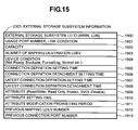
- Fig. 15 is a view showing an example of the external storage subsystem information 2303.
- the external storage subsystem information 2303 shown in Fig. 15 relates to a LU of the second storage system 20 which is capable of being the destination of an I/O request issued by the external storage connection mechanism 24 of the storage system 2 on the basis of an I/O request from the host computer 1.
- the storage system 2 comprises the external storage subsystem information 2303 for the maximum number of LUs of the second storage system 20 that can be supported by the storage system 2.
- An ID 1900 of the external storage subsystem LU serves as identification information for identifying a LU of the second storage system 20. More specifically, the ID 1900 is a set comprising a port ID (WWN) and host LUN of the second storage system 20 for identifying the LU.
- a usage port number 1901 is the port ID (in other words, the identification number of a port provided in the storage system 2) of the target device in the storage system 2 to which the LDEV of the storage system 2 corresponding to the LU is path defined.
- a LINK condition 1901 is information indicating whether the LINK between the LU and the port of the storage system 2 is ON or OFF.
- a capacity 1902 is the capacity of the LDEV of the second storage system 20 which is allocated to the LU.
- a mapping destination LDEV number 1903 is the identification number of the LDEV in the storage system 2 to which the LU corresponds.
- a device condition 1904 is information expressing the device condition of the LU, in which Not Ready is registered to indicate that the LU is not path defined, Blockade is registered to indicate a blocked condition, Formatting is registered to indicate that formatting is underway, Normal is registered to indicate a normal condition, and so on, for example.
- a connection definition setting time 1905 is information indicating the time at which the LU is allocated to the LDEV of the storage system 2 specified by the mapping destination LDEV number 1903.
- a connection definition detachment setting time 1906 is information indicating the estimated time at which the relationship between the LU and the LDEV specified by the mapping destination LDEV number 1903 is to be detached.
- a latest connection definition setting time 1907 is information indicating the time at which the LU was previously allocated to an LDEV of the storage system 2
- a latest connection definition detachment time 1908 is information indicating the time at which a previous relationship between the LU and the LDEV of the storage system 2 was detached.
- a previous mapping LDEV number 1912 is the LDEV number of the LDEV of the storage system 2 to which the LU was previously allocated
- a previous connection port number 1913 is the port ID (that is, identification information for a port of the storage system 2) of the port in the storage system 2 which was used when the LU was previously allocated to the LDEV of the storage system 2.
- An attribute 1909 is the attribute of the LDEV of the second storage system 20 that is path defined to the LU, and similarly to the attribute 1008 in the LDEV information 216 shown in Fig. 7, attribute types include read/write, read only, protect, SVOL-disable, and so on.
- An attribute setting time 1910 is information indicating the time at which the attribute 1909 is set, and an attribute modification prohibition period 1911 is information indicating a time period from the attribute setting time 1910 during which modification of the attribute set in the attribute 1909 section is prohibited.
- processing to obtain the configuration information 218 through the host computer 1 is similar to the processing of the first embodiment shown in Fig. 9.
- the information prepared by the configuration control program 210 further comprises the external storage subsystem information 2303 relating to the LUs of the second storage system 20 that may be allocated to LDEVs which may be attached to a target device that is accessible from the host computer.
- the host computer 1 is capable of using the configuration information 218 obtained by the processing shown in Fig. 9, which was performed using the storage system manager program 313, to exchange a LU of the second storage system 20 corresponding to an LDEV using the juke box system manager program 314.
- Fig. 13 shows an example of this processing in which the juke box system 6 is capable of relating a second external LU 22 of the second storage system to the first LDEV 8, which is path defined to the target device 7, in place of a first external LU 21 of the second storage system corresponding to the first LDEV 8.
- detachment processing will be described using an example of a case in which the allocation of the first external LU 21 to the first LDEV is disengaged.
- Fig. 16 is a view showing an example of detachment processing for disengaging a LU of the second storage system 20, which is allocated to an LDEV that is path defined to the target device of the storage system 2, from the storage system 2.
- the juke box system manager program 314 halts input/output processing on the first LDEV (step 1601). More specifically, the juke box system manager program 314 halts the input/output processing of the application which performs input/output processing on the target device to which the first LDEV is allocated, and at the same time transmits a write command to the storage system to ensure that data which have been cached in the memory 302 of the host computer 1 during the input/output processing executed on the target device up to the present, but have not yet been written into the storage system 2, are written into the storage system 2.
- This write command is received by the command control program 208 of the storage system 2, whereupon write processing is executed by the external storage subsystem connection program 2301 to write these data into the first LU of the second storage system 20 which is allocated to the first LDEV (not shown in the drawing).
- the juke box system manager program 314 transmits to the juke box system 6 (or in other words the command device) a read only attribute assignment command requesting that from now on, only read processing be permitted on the first LU (step 1602).
- the read only attribute assignment command issued by the juke box system manager program 314 takes the format shown in Fig. 19D.
- the read only attribute assignment command 2003 comprises a set of a port ID (WWN) and a host LUN of the storage system 2 specifying the target device that is path defined with the first LDEV to which the subject first LU is allocated.
- the command control program 208 interprets the received command, and specifies the identification information (i.e. the port ID (WWN) and host LUN of the storage system 2) of the first LU which is the object of read only attribute assignment by referring to the access-permitted host list 219, the target device-LDEV mapping information 214, the LDEV information 216, and the external storage subsystem information 2303.
- the command control program 208 then instructs the external storage subsystem connection program 2301 to assign a read only attribute to the specified first LU (step 1604).
- the external storage subsystem connection program 2301 updates the attribute 1909 of the external storage subsystem information 2303 corresponding to the WWN and host LUN to a read only attribute (step 1605). Further, the current time is set in the attribute setting time 1910, and the period specified by the read only attributeassignmentcommandissetintheattributemodification prohibition period 1911. The external storage subsystem connection program 2301 then transmits notification of the completion of read only attribute assignment to the command control program 208 (step 1606).
- the command control program 208 Having received this notification of the completion of read only attribute assignment, the command control program 208 transmits a read only attribute assignment completion response to the host computer 1 (step 1607).
- the juke box system manager program 314 in the host computer transmits a detach command to the juke box system 6 (step 1609).
- the detach command specifies the port ID (WWN) and host LUN set of the storage system 2, which serve as identification information for the target device that is subject to processing, the LDEV number of the first LDEV that is subject to processing, and the port ID (WWN) and host LUN of the second storage system 20, which serve as identification information for the first LU that is subject to processing.
- the command control program 208 analyzes the command and transmits a detachment request to the path control program 209 (step 1610).
- the path control program 209 uses the access-permitted host list 219 to specify the WWN and internal LUN of the target device which is the subj ect of the detachment request (step 1611) .
- the path control program 209 then checks whether the specified target device is implemented, whether the target device is faulty, whether the host computer 1 which transmitted the detach command is authorized to access the target device, and so on. This information can be confirmed by referring to the target device-LDEV mapping information 214, the access-permitted host list 219, and so on in the configuration information 218.
- the path control program 209 also specifies the first LDEV which is the subject of the detachment request, and confirms that this LDEV is path defined to the target device specified in step 1611 (step 1612).
- the path control program 209 also specifies the first LU to be detached by referring to the LDEV information 216 and external storage subsystem information 2303, and confirms that this first LU is allocated to the first LDEV specified in step 1612 (step 1613).
- the path control program 209 creates definition information for disengaging the path definition between the first LDEV and the first LU, and notifies the configuration control program 210 of the disengagement of the path definition together with the created definition information (step 1614).
- the configuration control program 210 rewrites the LDEV information 216 relating to the first LDEV, and registers a null in the section for the pointer 1011 to the external storage subsystem information (step 1616). The configuration control program 210 then notifies the path control program 209 that the LDEV information update is complete.
- the path control program 209 instructs the external storage subsystem connection program 2301 to disengage the path definition between the first LDEV and the first LU (step 1618) .
- the external storage subsystem connection program 2301 disengages the path definition between the first LU and first LDEV (step 1619) . More specifically, the external storage subsystem connection program 2301 updates the external storage subsystem information 2303 relating to the first LU, sets the LINK condition 1901 to OFF, records the value registered in the connection definition setting time 1905 in the latest connection definition setting time 1907, records the current time in the latest connection definition detachment time 1908, records the LDEV number of the first LDEV, which is registered in the mapping destination LDEV number 1903, in the previous mapping LDEV number 1912, and records the port number registered in the usage port number 1901 in the previous connection port number 1913 (step 1620). The external storage subsystem connection program 2301 then transmits a detachment completion response to the path control program 209.
- the path control program 209 Having received the detachment completion response from the external storage subsystem connection program 2301, the path control program 209 transmits a detachment completion response to the command control program 208 (step 1621).
- the command control program 208 transmits a detachment completion response to the host computer 1 (step 1622).
- the juke box system manager program 314 Having received the detachment completion response (step 1623), the juke box system manager program 314 outputs the completed information to the display device 304, and ends detachment processing.
- step 1602 to step 1608 may be omitted in certain cases.
- the first LU is disengaged from the first LDEV when the detach command is issued from the host computer 1, but the processing from step 1604 to step 1607 and from step 1610 to step 1622 may be executed automatically in the storage system 2 when the connection definition detachment setting time 1906 of the external storage subsystem information 2303 is reached.
- Fig. 19F is a view showing an example of the detach command that is issued in step 1609.
- the detach command comprises "JUKE BOX", indicating the juke box system (command device) that is the destination of the command, "Detach Device", indicating that the command is a detach command, a port ID (WWN) and host LUN serving as the identification information of the target device subject to detachment, an LDEV number indicating the first LDEV subject to detachment, a port ID (WWN) and host LUN serving as the identification information of the LU in the second storage system 20 which is attached to the first LDEV, and information indicating that the LU may be set in a WORM format as an option, and specifying the time period for setting the LU in a WORM format.
- the External Dev section of the detach command denotes that the detachment subject is a LU of the second storage device 20.
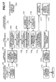
- Fig. 17 is a view showing an example of attachment processing for newly allocating the second LU to the first LDEV in order to set a path definition to the second LU of the second storage system 20 from the target device of the storage system 2 via the first LDEV.
- Attachment processing will be described using an example in which, following the processing shown in Fig. 16, the juke box function is used to newly allocate the second LU of the second storage system 20 to the first LDEV, which is path-defined to the target device.
- the juke box system manager program 314 transmits an attach command to the juke box system 6 of the storage system 2 (in other words to the command device) indicating that the second LU of the second storage system 20 is to be allocated to the first LDEV (step 1701).
- the attach command comprises identification information (i.e. a set of the port ID (WWN) and host LUN of the storage system 2) for the target device which is the subject of the attach command, the LDEV number of the first LDEV allocated to the target device, and identification information (i.e. a set of a port ID (WWN) and host LUN of the second storage system 20) for the second LU of the second storage system 20 to be newly allocated to the first LDEV.
- identification information i.e. a set of the port ID (WWN) and host LUN of the storage system 2
- the command control program 208 analyzes the command to determine that the command relates to input/output processing on the juke box system 6 and that the content of the command is an attachment request to allocate the second LU of the second storage system 20 to the first LDEV, and then transmits an attachment request to the path control program 209 requesting that the second LU of the second storage system 20 be allocated to the first LDEV (step 1702).
- the path control program 209 specifies the identifiers (i.e. a port ID (WWN) and internal LUN of the storage system 2) of the target device that is the subject of the received attachment request on the basis of the attachment request (step 1703). This processing may be performed by referring to the access-permitted host list 219.
- WWN port ID
- internal LUN internal LUN of the storage system 2
- the path control program 209 specifies the first LDEV which is the subject of the attachment request (step 1704).
- the path control program 209 then confirms that the specified first LDEV is path defined to the target device specified in step 1703, and that the LU of the second storage system 20 is not path defined to the specified LDEV.
- This processing may be performed by referring to the configuration information 218, and particularly the target device-LDEV mapping information 214 and LDEV information 216.
- the path control program 209 also specifies the second LU of the second storage system 20 that is the subject of the attachment request (step 1705).
- the path control program 209 then confirms that the second LU is in a normal condition (not faulty) , the LU is not path defined to the target device of the storage system 2, the LU has not been allocated to the target device by the juke box system up to the present, and so on.
- This information canbe confirmed by referring to the device condition 1904, usage port number/LINK condition 1901, mapping destination LDEV number 1903, and latest connection definition setting time 1907 in the external storage subsystem information 2303.
- the path control program 209 creates definition information for allocating the second LU of the second storage system 20 to the first LDEV specified by the attach command, and transmits notification of the path definition to the configuration control program 210 together with the definition information (step 1706).
- the configuration control program 210 updates the LDEV information 216 relating to the first LDEV on the basis of the received definition information, and records the storage position in the memory 204 of the external storage subsystem information 2303 relating to the first LU in the pointer 1011 to the external storage subsystem information (step 1708).
- the configuration control program 210 then notifies the path control program 209 that updating of the LDEV information 216 is complete.
- the external storage subsystem connection program 2301 allocates the second LU of the second storage system 20 to the first LDEV (step 1711) , and updates the external storage subsystem information 2303 relating to the second LU (step 1712). More specifically, in the external storage subsystem information 2303 relating to the second LU, the port ID (WWN) of the storage system 2 specified in step 1703 is recorded in the usage port number 1901, and the LINK condition 1901 is set to ON. Further, the LDEV number of the first LDEV specified in step 1704 is set in the mapping destination LDEV number 1903, the current time is set in the connection definition setting time 1905, and the time specified in the attach command is set in the connection definition detachment setting time 1906. The external storage subsystem connection program 2301 then notifies the path control program 209 of the completion of attachment.
- WWN port ID
- the path control program 209 transmits an attachment completion response to the command control program 208 (step 1713), whereupon the command control program 208 transmits an attachment completion response to the host computer 1 (step 1714).
- the juke box system manager program 314 When the host computer 1 receives the attachment completion response (step 1715), the juke box system manager program 314 reacknowledges the target device, and if the capacity of the device has altered, detects this and confirms the capacity of the new second LU. The juke box system manager program 314 then allows I/O processing to recommence on the target device, writes the identification information of the target device, the identification information of the host computer 1 (or the juke box system manager 5) , and the date and time at which the path definition was set in a specific region of the newly allocated second LU, and then ends the processing.
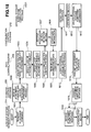
- the juke box system manager program 314 transmits to the juke box system 6 (or in other words the command device) an attach command (step 1801).
- the attach command comprises identification information (a port ID (WWN) and host LUN set of the storage system 2) for the target device which is the subj ect of the attach command, the LDEV number of the LDEV allocated to the target device, and identification information (a port ID (WWN) and host LUN set of the second storage system 20) for the LU of the second storage system 20 that is to be reattached to the LDEV.
- the command control program 208 interprets the command to be an attach command, and transmits an attachment request to the path control program (step 1802).
Landscapes
- Engineering & Computer Science (AREA)
- Theoretical Computer Science (AREA)
- Human Computer Interaction (AREA)
- Physics & Mathematics (AREA)
- General Engineering & Computer Science (AREA)
- General Physics & Mathematics (AREA)
- Information Retrieval, Db Structures And Fs Structures Therefor (AREA)
- Memory System Of A Hierarchy Structure (AREA)
Applications Claiming Priority (4)
| Application Number | Priority Date | Filing Date | Title |
|---|---|---|---|
| JP2003432014 | 2003-12-26 | ||
| JP2003432014 | 2003-12-26 | ||
| JP2004238983A JP4463042B2 (ja) | 2003-12-26 | 2004-08-19 | ボリュームの動的割り付け機能を有する記憶装置システム |
| JP2004238983 | 2004-08-19 |
Publications (2)
| Publication Number | Publication Date |
|---|---|
| EP1548560A2 true EP1548560A2 (de) | 2005-06-29 |
| EP1548560A3 EP1548560A3 (de) | 2008-11-05 |
Family
ID=34554873
Family Applications (1)
| Application Number | Title | Priority Date | Filing Date |
|---|---|---|---|
| EP04027413A Withdrawn EP1548560A3 (de) | 2003-12-26 | 2004-11-18 | Speichersystem mit einer Funktion zur dynamischen Volumenzuordnung |
Country Status (3)
| Country | Link |
|---|---|
| US (4) | US7392364B2 (de) |
| EP (1) | EP1548560A3 (de) |
| JP (1) | JP4463042B2 (de) |
Families Citing this family (21)
| Publication number | Priority date | Publication date | Assignee | Title |
|---|---|---|---|---|
| JP4307202B2 (ja) * | 2003-09-29 | 2009-08-05 | 株式会社日立製作所 | 記憶システム及び記憶制御装置 |
| JP4987307B2 (ja) * | 2005-03-25 | 2012-07-25 | 株式会社日立製作所 | ストレージシステム |
| JP4896500B2 (ja) * | 2005-11-14 | 2012-03-14 | 株式会社日立製作所 | 機器停止を伴う仮想ボリューム制御方法 |
| US7765365B2 (en) * | 2005-11-18 | 2010-07-27 | Lsi Corporation | Method of partioning storage in systems with both single and virtual target interfaces |
| JP4908872B2 (ja) * | 2006-02-21 | 2012-04-04 | 株式会社日立製作所 | 計算機システム、管理計算機及び記憶領域の管理方法 |
| JP4839133B2 (ja) * | 2006-05-22 | 2011-12-21 | 株式会社日立製作所 | ストレージ装置のデータ管理方法及び計算機システム |
| JP2007323284A (ja) | 2006-05-31 | 2007-12-13 | Hitachi Ltd | 計算機システム、ストレージシステム及び帯域管理方法 |
| JP2008077290A (ja) | 2006-09-20 | 2008-04-03 | Hitachi Ltd | 情報処理装置及び情報処理方法並びにストレージシステム |
| US7734889B1 (en) * | 2006-12-22 | 2010-06-08 | Emc Corporation | Methods and apparatus for distributing information to multiple nodes |
| JP5042660B2 (ja) | 2007-02-15 | 2012-10-03 | 株式会社日立製作所 | ストレージシステム |
| JP2009064160A (ja) | 2007-09-05 | 2009-03-26 | Hitachi Ltd | 計算機システム、管理計算機及びデータ管理方法 |
| US8099524B2 (en) * | 2008-10-01 | 2012-01-17 | International Business Machines Corporation | Automated method to configure a data storage system |
| TWI550407B (zh) * | 2009-04-22 | 2016-09-21 | 普安科技股份有限公司 | 資料存取的方法及執行該方法的裝置 |
| US8250284B2 (en) | 2009-10-23 | 2012-08-21 | Hitachi, Ltd. | Adaptive memory allocation of a second data storage volume based on an updated history of capacity of a first data volume |
| US8645649B2 (en) * | 2011-09-29 | 2014-02-04 | Hitachi, Ltd. | Computer system with reservation control |
| US9164880B2 (en) * | 2012-10-23 | 2015-10-20 | Hitachi, Ltd. | Method and apparatus for offloading storage workload |
| US10019203B1 (en) * | 2013-05-30 | 2018-07-10 | Cavium, Inc. | Method and system for processing write requests |
| US9268496B2 (en) | 2014-07-11 | 2016-02-23 | International Business Machines Corporation | Choosing a multipath I/O (MPIO) path control module (PCM) for a logical unit number (LUN) on a host that supports multiple PCMS |
| US9600692B2 (en) * | 2014-10-17 | 2017-03-21 | International Business Machines Corporation | Storage system security |
| US20180121091A1 (en) * | 2015-03-31 | 2018-05-03 | Hitachi, Ltd. | Storage apparatus and its control method |
| WO2022245334A1 (en) * | 2021-05-18 | 2022-11-24 | Siemens Aktiengesellschaft | Intelligent device extension for building software applications |
Citations (1)
| Publication number | Priority date | Publication date | Assignee | Title |
|---|---|---|---|---|
| EP1357476A2 (de) * | 2002-04-26 | 2003-10-29 | Hitachi, Ltd. | Verfahren zur Speichersystemsteuerung und Speichersteuerungsvorrichtung |
Family Cites Families (62)
| Publication number | Priority date | Publication date | Assignee | Title |
|---|---|---|---|---|
| US5197055A (en) * | 1990-05-21 | 1993-03-23 | International Business Machines Corporation | Idle demount in an automated storage library |
| US5193184A (en) * | 1990-06-18 | 1993-03-09 | Storage Technology Corporation | Deleted data file space release system for a dynamically mapped virtual data storage subsystem |
| US5745789A (en) * | 1992-01-23 | 1998-04-28 | Hitachi, Ltd. | Disc system for holding data in a form of a plurality of data blocks dispersed in a plurality of disc units connected by a common data bus |
| US5394532A (en) * | 1992-04-15 | 1995-02-28 | Storage Technology Corporation | Disk drive array memory system having instant format capability |
| JPH064979A (ja) | 1992-06-18 | 1994-01-14 | Ricoh Co Ltd | バッテリにより駆動されるデータ機器のディスク記憶装置の 節電力駆動制御方法 |
| US5404485A (en) * | 1993-03-08 | 1995-04-04 | M-Systems Flash Disk Pioneers Ltd. | Flash file system |
| JP2858542B2 (ja) * | 1994-06-03 | 1999-02-17 | インターナショナル・ビジネス・マシーンズ・コーポレイション | コンピュータ用ディスク・ドライブの電力消費を節減する方法及び装置 |
| KR0143529B1 (ko) * | 1994-06-22 | 1998-07-15 | 김광호 | 디스크 회전 제어 장치 및 방법 |
| US5860137A (en) * | 1995-07-21 | 1999-01-12 | Emc Corporation | Dynamic load balancing |
| JP3202600B2 (ja) * | 1996-06-27 | 2001-08-27 | 日本電気株式会社 | 磁気ディスク装置 |
| US6073218A (en) * | 1996-12-23 | 2000-06-06 | Lsi Logic Corp. | Methods and apparatus for coordinating shared multiple raid controller access to common storage devices |
| JP3228182B2 (ja) | 1997-05-29 | 2001-11-12 | 株式会社日立製作所 | 記憶システム及び記憶システムへのアクセス方法 |
| US6304940B1 (en) * | 1997-08-14 | 2001-10-16 | International Business Machines Corporation | Shared direct access storage system for MVS and FBA processors |
| US6038639A (en) * | 1997-09-09 | 2000-03-14 | Storage Technology Corporation | Data file storage management system for snapshot copy operations |
| US6125373A (en) * | 1997-09-19 | 2000-09-26 | Microsoft Corporation | Identifying a driver that is an owner of an active mount point |
| US5963971A (en) * | 1997-10-09 | 1999-10-05 | International Business Machines Corporation | Method and apparatus for handling audit requests of logical volumes in a virtual media server |
| US6105103A (en) * | 1997-12-19 | 2000-08-15 | Lsi Logic Corporation | Method for mapping in dynamically addressed storage subsystems |
| US6725331B1 (en) | 1998-01-07 | 2004-04-20 | Emc Corporation | Method and apparatus for managing the dynamic assignment resources in a data storage system |
| US6295575B1 (en) * | 1998-06-29 | 2001-09-25 | Emc Corporation | Configuring vectors of logical storage units for data storage partitioning and sharing |
| US6591356B2 (en) * | 1998-07-17 | 2003-07-08 | Roxio, Inc. | Cluster buster |
| JP2000112822A (ja) | 1998-10-01 | 2000-04-21 | Hitachi Ltd | アーカイバル機能を有するディスク制御方式 |
| JP2000112666A (ja) | 1998-10-01 | 2000-04-21 | Hitachi Ltd | ディスク制御装置 |
| US6167459A (en) * | 1998-10-07 | 2000-12-26 | International Business Machines Corporation | System for reassigning alias addresses to an input/output device |
| US6356915B1 (en) * | 1999-02-22 | 2002-03-12 | Starbase Corp. | Installable file system having virtual file system drive, virtual device driver, and virtual disks |
| JP4325817B2 (ja) | 1999-04-05 | 2009-09-02 | 株式会社日立製作所 | ディスクアレイ装置 |
| US6754661B1 (en) * | 1999-07-13 | 2004-06-22 | Microsoft Corporation | Hierarchical storage systems for holding evidentiary objects and methods of creating and operating upon hierarchical storage systems |
| JP3843713B2 (ja) | 1999-08-27 | 2006-11-08 | 株式会社日立製作所 | 計算機システム及びそのデバイスの割り当て方法 |
| US6854034B1 (en) | 1999-08-27 | 2005-02-08 | Hitachi, Ltd. | Computer system and a method of assigning a storage device to a computer |
| US6839827B1 (en) * | 2000-01-18 | 2005-01-04 | International Business Machines Corporation | Method, system, program, and data structures for mapping logical blocks to physical blocks |
| US6760828B1 (en) * | 2000-06-27 | 2004-07-06 | Emc Corporation | Method and apparatus for using logical volume identifiers for tracking or identifying logical volume stored in the storage system |
| US6708265B1 (en) * | 2000-06-27 | 2004-03-16 | Emc Corporation | Method and apparatus for moving accesses to logical entities from one storage element to another storage element in a computer storage system |
| US6622177B1 (en) * | 2000-07-27 | 2003-09-16 | International Business Machines Corporation | Dynamic management of addresses to an input/output (I/O) device |
| US6977927B1 (en) * | 2000-09-18 | 2005-12-20 | Hewlett-Packard Development Company, L.P. | Method and system of allocating storage resources in a storage area network |
| US7792923B2 (en) * | 2000-10-13 | 2010-09-07 | Zhe Khi Pak | Disk system adapted to be directly attached to network |
| US6880058B2 (en) * | 2000-12-07 | 2005-04-12 | Hitachi, Ltd. | Computer system with storage system having re-configurable logical volumes |
| WO2002065275A1 (en) * | 2001-01-11 | 2002-08-22 | Yottayotta, Inc. | Storage virtualization system and methods |
| US7007141B2 (en) | 2001-01-30 | 2006-02-28 | Data Domain, Inc. | Archival data storage system and method |
| US6606690B2 (en) * | 2001-02-20 | 2003-08-12 | Hewlett-Packard Development Company, L.P. | System and method for accessing a storage area network as network attached storage |
| JP2002288108A (ja) * | 2001-03-28 | 2002-10-04 | Hitachi Ltd | 外部記憶装置 |
| JP4144727B2 (ja) * | 2001-07-02 | 2008-09-03 | 株式会社日立製作所 | 情報処理システム、記憶領域提供方法、およびデータ保持管理装置 |
| US6519678B1 (en) * | 2001-09-10 | 2003-02-11 | International Business Machines Corporation | Virtualization of data storage drives of an automated data storage library |
| JP4087097B2 (ja) * | 2001-11-12 | 2008-05-14 | 株式会社日立製作所 | データベース管理システム情報を考慮したデータ再配置方法およびデータ再配置を行う計算機システム |
| US7548975B2 (en) * | 2002-01-09 | 2009-06-16 | Cisco Technology, Inc. | Methods and apparatus for implementing virtualization of storage within a storage area network through a virtual enclosure |
| US7007152B2 (en) | 2001-12-28 | 2006-02-28 | Storage Technology Corporation | Volume translation apparatus and method |
| JP3993773B2 (ja) * | 2002-02-20 | 2007-10-17 | 株式会社日立製作所 | ストレージサブシステム、記憶制御装置及びデータコピー方法 |
| US20030156345A1 (en) * | 2002-02-20 | 2003-08-21 | Fayeulle Serge J. | Data storage device and method for spindle power control |
| US6912621B2 (en) * | 2002-04-17 | 2005-06-28 | International Business Machines Corporation | Method and apparatus for updating data in mass storage subsystem using emulated shared memory |
| JP2003316522A (ja) * | 2002-04-26 | 2003-11-07 | Hitachi Ltd | 計算機システムおよび計算機システムの制御方法 |
| US7185169B2 (en) * | 2002-04-26 | 2007-02-27 | Voom Technologies, Inc. | Virtual physical drives |
| US20030212859A1 (en) * | 2002-05-08 | 2003-11-13 | Ellis Robert W. | Arrayed data storage architecture with simultaneous command of multiple storage media |
| JP4100968B2 (ja) * | 2002-06-06 | 2008-06-11 | 株式会社日立製作所 | データマッピング管理装置 |
| JP4124331B2 (ja) * | 2002-09-17 | 2008-07-23 | 株式会社日立製作所 | Dbms向け仮想ボリューム作成・管理方法 |
| US6957303B2 (en) * | 2002-11-26 | 2005-10-18 | Hitachi, Ltd. | System and managing method for cluster-type storage |
| JP2004178337A (ja) * | 2002-11-28 | 2004-06-24 | Hitachi Ltd | 記憶装置システム、記憶装置、計算機およびプログラム |
| JP2004220450A (ja) * | 2003-01-16 | 2004-08-05 | Hitachi Ltd | ストレージ装置、その導入方法、及びその導入プログラム |
| JP2004302751A (ja) * | 2003-03-31 | 2004-10-28 | Hitachi Ltd | 計算機システムの性能管理方法、および、記憶装置の性能を管理する計算機システム |
| JP4266725B2 (ja) * | 2003-06-27 | 2009-05-20 | 株式会社日立製作所 | 記憶システム |
| US7068455B2 (en) * | 2003-07-21 | 2006-06-27 | Matsushita Electric Industrial Co., Ltd. | Method and system for reducing power consumption in a rotatable media data storage device |
| US7130973B1 (en) * | 2003-08-08 | 2006-10-31 | Sun Microsystems, Inc. | Method and apparatus to restore data redundancy and utilize spare storage spaces |
| JP2005190036A (ja) | 2003-12-25 | 2005-07-14 | Hitachi Ltd | 記憶制御装置及び記憶制御装置の制御方法 |
| JP2005266933A (ja) * | 2004-03-16 | 2005-09-29 | Fujitsu Ltd | ストレージ管理システム及びストレージ管理方法 |
| JP4230410B2 (ja) * | 2004-05-11 | 2009-02-25 | 株式会社日立製作所 | 仮想ストレージの通信品質制御装置 |
-
2004
- 2004-08-19 JP JP2004238983A patent/JP4463042B2/ja not_active Expired - Fee Related
- 2004-10-01 US US10/957,059 patent/US7392364B2/en not_active Expired - Fee Related
- 2004-11-18 EP EP04027413A patent/EP1548560A3/de not_active Withdrawn
-
2005
- 2005-12-19 US US11/305,134 patent/US7310713B2/en not_active Expired - Fee Related
-
2008
- 2008-04-30 US US12/149,293 patent/US7757058B2/en not_active Expired - Fee Related
-
2010
- 2010-06-09 US US12/796,702 patent/US7991974B2/en not_active Expired - Fee Related
Patent Citations (1)
| Publication number | Priority date | Publication date | Assignee | Title |
|---|---|---|---|---|
| EP1357476A2 (de) * | 2002-04-26 | 2003-10-29 | Hitachi, Ltd. | Verfahren zur Speichersystemsteuerung und Speichersteuerungsvorrichtung |
Also Published As
| Publication number | Publication date |
|---|---|
| US7991974B2 (en) | 2011-08-02 |
| US20050144384A1 (en) | 2005-06-30 |
| US7310713B2 (en) | 2007-12-18 |
| EP1548560A3 (de) | 2008-11-05 |
| US20100250886A1 (en) | 2010-09-30 |
| US7392364B2 (en) | 2008-06-24 |
| US20060095704A1 (en) | 2006-05-04 |
| US20080215812A1 (en) | 2008-09-04 |
| JP2005209149A (ja) | 2005-08-04 |
| US7757058B2 (en) | 2010-07-13 |
| JP4463042B2 (ja) | 2010-05-12 |
Similar Documents
| Publication | Publication Date | Title |
|---|---|---|
| US7757058B2 (en) | Storage system having dynamic volume allocation function | |
| US7020734B2 (en) | Connecting device of storage device and computer system including the same connecting device | |
| US8843715B2 (en) | System managing a plurality of virtual volumes and a virtual volume management method for the system | |
| US7793064B2 (en) | Storage system having a first computer, a second computer connected to the first computer via a network, and a storage device system that is accessed by the second computer | |
| US20070022259A1 (en) | Write protection in a storage system allowing both file-level access and volume-level access | |
| JP2004362028A (ja) | ストレージシステムの制御方法、ストレージシステム、及びストレージ装置 | |
| US7774543B2 (en) | Storage system, method for managing the same, and storage controller | |
| US7640415B2 (en) | Storage system having a first computer, a second computer connected to the first computer via a network, and a storage device system that is accessed by the second computer | |
| US7424572B2 (en) | Storage device system interfacing open-system host computer input/output interfaces | |
| EP1705575B1 (de) | Speichersystem mit dynamischem Einhängen von Datenspeicherungsvorrichtungen. | |
| JP2007257646A (ja) | ストレージ集中管理方法 |
Legal Events
| Date | Code | Title | Description |
|---|---|---|---|
| PUAI | Public reference made under article 153(3) epc to a published international application that has entered the european phase |
Free format text: ORIGINAL CODE: 0009012 |
|
| AK | Designated contracting states |
Kind code of ref document: A2 Designated state(s): AT BE BG CH CY CZ DE DK EE ES FI FR GB GR HU IE IS IT LI LU MC NL PL PT RO SE SI SK TR |
|
| AX | Request for extension of the european patent |
Extension state: AL HR LT LV MK YU |
|
| PUAL | Search report despatched |
Free format text: ORIGINAL CODE: 0009013 |
|
| AK | Designated contracting states |
Kind code of ref document: A3 Designated state(s): AT BE BG CH CY CZ DE DK EE ES FI FR GB GR HU IE IS IT LI LU MC NL PL PT RO SE SI SK TR |
|
| AX | Request for extension of the european patent |
Extension state: AL HR LT LV MK YU |
|
| 17P | Request for examination filed |
Effective date: 20081126 |
|
| RIN1 | Information on inventor provided before grant (corrected) |
Inventor name: NAGASOE, YASUYUKIC/O HITACHI, LTD. Inventor name: YAMAMOTO, YASUTOMOC/O HITACHI, LTD. Inventor name: EGUCHI, YOSHIAKIC/O HITACHI, LTD. |
|
| 17Q | First examination report despatched |
Effective date: 20090209 |
|
| AKX | Designation fees paid |
Designated state(s): DE FR GB IE |
|
| STAA | Information on the status of an ep patent application or granted ep patent |
Free format text: STATUS: THE APPLICATION HAS BEEN WITHDRAWN |
|
| 18W | Application withdrawn |
Effective date: 20140715 |