BACKGROUND OF THE INVENTION
1. Field of the Invention
The present invention relates to an image formation method
forming images on both faces of a recording medium, and an image
formation apparatus.
2. Description of the Background Art
Conventional image formation apparatus for forming images on
both faces of a recording medium having a first image formation
part to form the image on one face of the recording medium; and
a second image formation part to form the image on the other face
of the recording medium, are disclosed in, for example, Japanese
Patent Application Laid-open No. H11-38687 and Japanese Patent
Application Laid-open No. 2000-352889. In other words, the primary
image formation part is a first image formation unit comprising
image formation process devices such as an image carrier and the
like, and a first intermediate transfer belt wherein a toner image
(hereafter referred to as a 'primary image') on the afore-mentioned
image carrier is transferred. Similarly, the second image
formation part is a second image formation unit comprising image
formation process devices such as an image carrier and the like,
and a second intermediate transfer belt wherein a toner image
(hereafter referred to as a 'second image') on the afore-mentioned
image carrier is transferred. The first intermediate transfer belt
is provided at a position opposite the one face of the recording
medium to constitute the first transfer position. On the other
hand, the second intermediate transfer belt is provided at a
position opposite the other face of the recording medium to
constitute the second transfer position. By feeding the recording
medium to the first transfer position and second transfer position,
the first image is formed on one face of the recording medium, and
the second image is formed on the other face of the recording medium.
Images are thus formed on both faces of the recording medium.
However, in the case of such image formation apparatus, if
a fault and the like occurs in either the first or second image
formation unit, there is a problem that, if the prescribed
operation is no longer possible, image formation on both faces is
no longer possible.
Technologies relating to the present invention are (also)
disclosed in, for example, Japanese Patent Application Laid-open
No. 2002-189387.
SUMMARY OF THE INVENTION
With the foregoing in view, it is an object of the present
invention to provide an image formation method, and an image
formation apparatus for same, wherein images can be formed on both
faces even if the first or second image formation unit no longer
has the required functions.
In accordance with the present invention, provided is an
image formation method for transferring a first image created with
a first image formation unit to one face of a recording medium,
and transferring a second image created with a second image
formation unit to the other face of the recording medium, wherein,
if it is detected that either the first image formation unit or
the second image formation unit does not have required functions,
the image formation method is selected such that the first image
and the second image are formed with the one of the image formation
units having the required functions, the first image is transferred
to one face of the recording medium, and the second image is
transferred to the other face of the recording medium.
Also provided is an apparatus for forming images comprising:
a first image formation part comprising a first image formation
unit forming a first image and a first intermediate transfer body
on which the the first image is transferred; a second image
formation part comprising a second image formation unit forming
a second image and a second intermediate transfer body on which
the second image is transferred; a first transfer device to
transfer the first image to one side of a recording medium; a second
transfer device to transfer the second image to the other side of
the recording medium; a detection device to detect whether or not
the first image formation unit and the second image formation unit
have the required functions; and a switching device to switch, when
the detecting device has detected that either one of the first and
second image formation units does not have the required functions,
from an image formation method of forming the first image with a
first image formation unit, transferring the first image to the
first intermediate transfer body and then to one face of the
recording medium, forming the second image with a second image
formation unit, and transferring the second image to the second
intermediate transfer body and then to the other face of the
recording medium in accordance with the detection device, to an
image formation method of forming the first image and the second
image with the image formation unit having the required functions,
transferring the first image to the first intermediate transfer
body and then to one face of the recording medium and transferring
the second image to the second intermediate transfer body and then
to the other face of the recording medium.
BRIEF DESCRIPTION OF THE DRAWINGS
The above, and other objects, features, and advantages of the
present invention will become more apparent from the following
detailed description taken with the accompanying drawings in
which:
DESCRIPTION OF THE PREFERRED EMBODIMENTS
Description will be made of an embodiment wherein the image
formation apparatus of the present invention is applied.
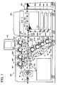
FIG. 1 shows the configuration of a full color printer capable
of double-faced printing by electrophotography, with the image
formation apparatus related to the present embodiment labeled as
100. As shown in the figure, the primary image formation part 20
is positioned above, and the second image formation part 30 is
positioned below, the recording medium feed path 43A within the
main body 100 of this image formation apparatus. The primary image
formation part 20 is provided with a first intermediate transfer
belt 21 moving endlessly in the direction of the arrow, and the
second image formation part 30 is provided with a second
intermediate transfer belt 31 moving endlessly in the direction
of the arrow. Four first image formation units 80Y, 80C, 80M, and
80K are positioned on the upper tensioned face of the first
intermediate transfer belt 21. On the other hand, four second image
formation units 81Y, 81C, 81M, and 81K are positioned on the upper
tensioned face of the second intermediate transfer belt 31. Y,
C, M, and K associated with the numbers of these primary and second
image formation units correspond to the colors of toner handled,
Y corresponding to yellow, C to cyan, M to magenta, and K to black.
The same Y, C, M, and K are applied to the photoreceptors 1 provided
in the first and second image formation units and rotate together
with the first intermediate transfer belt 21 and second
intermediate transfer belt 31. The photoreceptors 1Y through 1K
are positioned equidistantly within the image formation parts 20
and 30, and in contact with at least part of the upper tensioned
face of the intermediate transfer belts 21 and 31 respectively
during image formation.
An electrostatic charging apparatus, an exposure apparatus,
a developing apparatus, and a cleaning apparatus are provided near
each photoreceptor 1K, 1M, 1C, and 1Y as image formation process
devices. The electrostatic charging apparatus uniformly charges
the surface of the photoreceptor rotated clockwise in the figure
by a drive device (not shown). The image read by the manuscript
reader apparatus 200 onto the uniformly charged photoreceptor
surface is formed as an electrostatic latent image by the exposure
apparatus. This electrostatic latent image is developed into a
toner image by the developing apparatus. A transfer bias is then
applied to the primary transfer rollers 22 and 32 (described later),
and the toner image on the photoreceptor is primary-transferred
onto the first or second intermediate transfer belts. The cleaning
apparatus removes toner remaining on the surface of the
photoreceptor following the primary transfer process.
Furthermore, reflective photosensors (hereafter referred to
as 'P sensors') 2K, 2M, 2C, and 2Y are provided near the
photoreceptors 1K, 1M, 1C, and 1Y as a detection device to detect
the density of the toner image formed on the photoreceptors 1. The
P sensor 2 comprises a light emitting device consisting of a light
emitting diode and the like as a light emitting part, and a
photosensitive device consisting of a photosensor such as a
phototransistor and the like as a light receiving part. The light
radiated from this light emitting part illuminates the prescribed
location on the photoreceptor 1, and the amount of light reflected
is detected by the light receiving part. This detection result
is output from the P sensor 2 as a DC voltage. Here, the
afore-mentioned amount of reflected light varies with the amount
of toner adhering at the prescribed position on the photoreceptor
1. In other words, the value of the voltage output from the P sensor
2 varies with the amount of toner adhering at the prescribed
position on the photoreceptor 1. Thus; the amount of toner adhering
at the prescribed position is known. In the copier of the present
embodiment, the value of the voltage output from the P sensor 2
decreases as the amount of toner adhering increases.
The afore-mentioned output voltage value is controlled by a
PWM controller. The CPU varies the magnitude of the control signal
to this PWM controller (hereafter referred to as the 'PWM value'),
and thus the DC voltage supplied to the P sensor 2 (hereafter
referred to as the 'output voltage value') can be varied.
The optical density of the standard image formed on the
photoreceptors 1K, 1M, 1C, and 1Y is detected with the P sensors
2K, 2M, 2C, and 2Y. Based on this detection result, the necessary
amount of toner is supplied from the toner hopper 7a to the
developer mixing part of the developing unit 3 to approach the
prescribed density.
Image density detection executes process control operation
to ensure the correct image density for each color when power is
switched on, or with the prescribed number of copies. A density
detection patch (hereafter referred to as a 'standard pattern')
is formed on each photoreceptor 1K, 1M, 1C, and 1Y during this
process control operation. The standard pattern formed on each
photoreceptor 1K, 1M, 1C, and 1Y is employed as a standard pattern
of continuous gradation by selecting electrostatic bias and
developing bias in sequence. In other words, in the present
embodiment, the line-format standard pattern wherein the amount
of toner adhering varies in gradations is created in the direction
of movement of the surface of the photoreceptor. This standard
pattern is then detected with the P sensor. Based on this detection
result, the necessary amount of toner is supplied from the toner
hopper to the developing apparatus to approach the prescribed
density. When toner has not been supplied to the developing
apparatus, toner becomes insufficient, and the toner image on the
photoreceptor becomes lighter. In this condition, it is determined
that [the photoreceptor] does not have the required functions, and
operating mode of the image formation device (described later) is
switched.
Furthermore, the afore-mentioned sensor can also be used to
detect deterioration of the surface of the photoreceptor. P
sensors 2K, 2M, 2C, and 2Y detect these defects, using the
reduction in the reflectance ratio of the surface of the
photoreceptor 1 and the [consequent] reduction in the amount of
light reflected from the photoreceptor drum 1 when the surface of
the photoreceptor 1 is damaged or becomes coated with a film of
foreign matter. Detection of deterioration of the surface of the
photoreceptor is executed automatically when power is switched on.
Firstly, an electrostatic voltage and developing bias voltage are
applied with the photoreceptors 1K, 1M, 1C, and 1Y rotated in the
same manner as with normal image formation, and a non-image area
created on the surface of the photoreceptors 1. The light is
radiated by the light emitting element of the P sensor 2 onto this
area, and the amount of light emitted by the P sensor 2, in other
words, the value of the current flowing in the light emitting
element is PWM-controlled so that the non-image output voltage of
the P sensor 2 (Vsg) resulting from detection of light reflected
from photoreceptor 1 by the photosensor element is 4.0. This PWM
value is expressed in 256 steps, and is normally set to between
70 and 75 when a new photoreceptor drum 1 is used. The upper limit
of the PWM value is set to 120, and when the actual PWM value exceeds
this value, in other words, when this value exceeds 120, the amount
of light reflected by the P sensor 2 is insufficient and is
determined to be an abnormal value. In other words, when the PWM
value exceeds 120, the surface of the photoreceptor is determined
to have deteriorated and to no longer have the required functions,
and the operating mode is switched (described later).
Next, description will be made of the intermediate transfer
belt.
As the primary intermediate transfer body, the first
intermediate transfer belt 21 is supported by a plurality of
rollers 23, 24, 25, 26 (two), 27, 28, and 29 running in the direction
of the arrow, and provided in the bottom of the photoreceptors 1Y,
1C, 1M, and 1K in the first image formation units 80Y through 80K.
This first intermediate transfer belt 21 is endless, and is
tensioned and positioned so that it is in contact with part of each
photoreceptor. Furthermore, the primary transfer rollers 22 are
provided on the inner periphery of the first intermediate transfer
belt 21 opposite the photoreceptors 1Y, 1C, 1M, and 1K. The
cleaning apparatus 20A is provided at a position opposite the
roller 23 on the outer periphery of the first intermediate transfer
belt 21. This cleaning apparatus 20A wipes and removes excess toner
and paper dust and the like remaining on the surface of the first
intermediate transfer belt 21. The first intermediate transfer
belt 21, the first image formation units 80Y, 80C, 80M, and 80K,
and the cleaning apparatus 20A are integrated to comprise the first
image formation unit 20 being removable from the image formation
apparatus 100.
On the other hand, the second intermediate transfer belt 31
corresponding to a second intermediate transfer body is supported
by a plurality of rollers 33, 34, 35, 36 (two), and 38 running in
the direction of the arrow. Furthermore, the second intermediate
transfer belt 31 is tensioned by the tension roller 37, and provided
in contact with the photoreceptors 1Y, 1C, 1M, and 1K in the second
image formation units 81Y through 81K. This second intermediate
transfer belt 31 is endless, and is tensioned and positioned so
that it is in contact with part of each photoreceptor after the
developing process. The primary transfer rollers 32 are provided
on the inner periphery of the second intermediate transfer belt
31 opposite the photoreceptors 1Y, 1C, 1M, and 1K.
The cleaning apparatus 30A is provided at a position opposite
the roller 33 on the outer periphery of the second intermediate
transfer belt 31. This cleaning apparatus 30A wipes and removes
excess toner and paper dust and the like remaining on the surface
of the intermediate transfer belt 31.
The second intermediate transfer belt 31, the second image
formation units 81Y, 81C, 81M, and 81K, and the cleaning apparatus
30A are integrated to comprise the second image unit 30 being
removable from the image formation apparatus 100.
Furthermore, the separation mechanism 210 is provided as a
separation device to separate the intermediate transfer belts from
the photoreceptors. Description will be made of the separation
mechanism separating the second intermediate transfer belt 31 from
the photoreceptors 1Y through 1K. FIG. 2 is a perspective view
showing the separation mechanism 210, FIG. 3A is a view showing
the second image formation part while the separation mechanism is
not in operation, and FIG. 3B is a view showing the second image
formation part while the separation mechanism is in operation. The
separation mechanism 210 shown in FIG. 2 has a roller retaining
member 201 provided with a base plate 201c. Four primary transfer
rollers 32, rollers 36 (two), and roller 35 are retained between
side plates 201a and 201b of the roller retaining member 201. The
plunger 203 is fitted to the base plate 201c of the roller retaining
member 201. Furthermore, the spring 202 is fitted to the roller
retaining member 201, forcing the roller retaining member 201
towards the photoreceptor. The roller 35 shaft 35a is passed
through the roller retaining member 201 side plates 201a and 201b,
and the roller 35 shaft 35a passed through the side plates is fitted
to the side plates (not shown) of the image forming apparatus. Thus,
the roller retaining member 201 may rotate on the center of the
roller 35.
When at least one of the second image formation units 81Y,
81M, 81C, and 81K loses the function of being able to satisfactorily
form an image due to deterioration of the photoreceptor or
insufficient toner and the like, the plunger 203 draws the roller
retaining member 201 in the downwards direction in the figure. The
roller retaining member 201 then rotates on the center of the roller
35, and as shown in FIG. 3B, the roller 36 and the four primary
transfer rollers 32 separate from the second intermediate transfer
belt 31. The second intermediate transfer belt pressed against
the photoreceptor by the roller 36 and four primary transfer
rollers 32 attempts to bend, however it is re-tensioned by the
tension roller 37. As a result, as shown in FIG. 3B, the second
intermediate transfer belt 31 separates from the photoreceptor.
On the other hand, when a deteriorated photoreceptor is
replaced and the like, and the second image formation unit has
recovered the required functions, the drawing [action] of the
plunger 203 is cleared. The roller retaining member 201 moves
towards the photoreceptor around the center of the roller 35 by
the force of the spring 202, and as shown in FIG. 3A, the four
primary transfer rollers 32 contact the photoreceptors via the
second intermediate transfer belt 31.
Description has been made above of the second image formation
part, however the primary image formation part is of the same
configuration. In other words, a roller retaining member retaining
the roller 25, four primary transfer rollers 22, and two rollers
26, is provided. A spring and plunger are fitted to this roller
retaining member, the spring forcing the roller retaining member
towards the photoreceptor. Furthermore, the roller retaining
member can rotate around the center of the roller 25. The roller
retaining member rotates around the center of the roller 25 due
to the drawing [action] of the plunger, and is separated from the
photoreceptor. Separation of the roller retaining member from the
photoreceptor also separates the four primary transfer rollers 22
contacting the photoreceptors via the first intermediate transfer
belt from the photoreceptors. The first intermediate transfer belt
21 attempts to bend due to this separation, however it is tensioned
again by the tension roller 27. As a result, the first intermediate
transfer belt 21 separates from the photoreceptors. On the other
hand, when the drawing [action] of the plunger is cleared, the
roller retaining member moves towards the photoreceptor due to the
spring force, and the four primary transfer rollers 22 each contact
a photoreceptor via the first intermediate transfer belt 21. Thus
the photoreceptors and the intermediate transfer belt are again
brought into contact.
The separation mechanism is not limited to the above.
For example, an eccentric cam 302 may be provided as a separation
mechanism in each image formation unit 80Y through 80K and 81Y
through 81K. The image formation unit is moved with this eccentric
cam 302, separating, the photoreceptor and intermediate transfer
belt. An example wherein the eccentric cam 302 is provided in the
image formation unit 81K will be described below, however other
image formation units have the same configuration. FIG. 4A and
4B are views showing a configuration wherein the eccentric cam is
provided in the image formation unit 81K. FIG. 4A is a view showing
the photoreceptor 1K and the second intermediate transfer belt 31
in contact, and FIG. 4B is a view showing the photoreceptor 1K and
the second intermediate transfer belt 31 separated. The image
formation unit 81K is enclosed within the frame 301 together with
the photoreceptor and image formation process devices
(electrostatic charging apparatus, exposure apparatus, developing
apparatus, and cleaning apparatus). Furthermore, the image
formation unit 81K is forced in the direction of separation from
the second intermediate transfer belt 31 by a forcing device (not
shown). The frame 301 of the image formation unit 81K contacts
the eccentric cam 302. When the image formation unit 81K loses
the function of being able to satisfactorily for an image due to
deterioration of the photoreceptor or insufficient toner and the
like, the eccentric cam 302 constituting the separation mechanism
rotates. The image formation unit 81K is then separated from the
second intermediate transfer belt 31, assuming the condition shown
in FIG.4B. When a deteriorated photoreceptor is replaced and the
like, and the second image formation unit 81K has recovered the
required functions, the eccentric cam 302 is rotated and the image
formation unit and the second intermediate transfer belt 31 are
brought into contact.
Furthermore, as shown in FIG. 1, the first intermediate
transfer belt 21 and the second intermediate transfer belt 31 are
endless and move in the forward direction while in mutual contact
to constitute the secondary transfer nip.
Furthermore, the first intermediate transfer belt 21 is
tensioned within the afore-mentioned secondary transfer nip, and
the first secondary transfer roller 46 is provided at a position
opposite the grounded support roller 28. This first secondary
transfer roller 46 is provided on the inner periphery of the second
intermediate transfer belt 31, and contacts the inner peripheral
surface of the second intermediate transfer belt. A transfer bias
opposite to that of the toner is applied to the secondary transfer
roller 46 from the power supply (not shown), and a 50µA transfer
current flows. By [introducing] the transfer current in the first
secondary transfer roller 46 while passing the paper P between the
first intermediate transfer belt 21 and the secondary transfer
roller 46, the image is transferred to the paper P with the toner
carried by the first carrier belt 21.
The second intermediate transfer belt 31 is tensioned within
the afore-mentioned secondary transfer nip, and the second
secondary transfer roller 47 is provided at a position opposite
the grounded support roller 34. This second secondary transfer
roller 47 is provided on the inner periphery of the first
intermediate transfer belt 21, and contacts the inner peripheral
surface of the first intermediate transfer belt 21. A transfer
bias of polarity opposite to that of the toner is applied to the
secondary transfer roller 47 from the power supply (not shown)
introducing a 50µA transfer current. By introducing the transfer
current while passing the paper P between the second intermediate
transfer belt 31 and the secondary transfer roller 47, the image
is transferred to the paper P with the toner image carried by the
second intermediate transfer belt 31.
In the present embodiment, the image is transferred to the
paper by introducing the transfer current in the secondary transfer
rollers 46 and 47, however the image may also be transferred to
the paper by applying a transfer voltage to the secondary transfer
rollers 46 and 47. Furthermore, a transfer bias of a polarity
opposite to that of the toner is applied to the secondary transfer
rollers 46 and 47 in secondary transfer in the present embodiment,
however, a method wherein a transfer bias of the same polarity as
that of the toner is applied may also be used. In this case, only
the grounded support roller and the secondary transfer roller need
be changed. In practice, the secondary transfer rollers wherein
a transfer bias of the same polarity as that of the toner is applied
are the support rollers 28 and 34, and the secondary transfer
rollers 46 and 47 are grounded, to transfer the image on the
intermediate transfer belt to the paper.
The paper supply apparatus 40 enclosing paper for supply is
positioned at the right of the image formation apparatus 100. A
plurality of stages, for example, a paper supply apparatus (tray)
40a enclosing a large amount of paper in the upper stage, and three
stages of paper cassettes 40b, 40c, and 40d below able to be
perpendicularly removed to the front (towards the operating panel) ,
are provided. Different types of paper P are enclosed in the paper
tray 40a and paper cassettes 40b, 40c, and 40d. Of these, the paper
in the topmost position is selectively supplied and separated by
the corresponding paper supply and separation devices 41a through
41d and fed to the recording medium feed path 43B and 43A one sheet
at a time by a plurality of pairs of feed rollers 42B.
A pair of register rollers 45 are provided in the recording
medium feed path 43A to obtain supply timing for feeding the paper
P to the secondary transfer position being the first and second
transfer positions. Furthermore, a horizontal registration
compensation mechanism 44 is provided in the recording medium feed
path 43A to correct the position in the direction relative to the
feed direction of the paper to the normal P sensor.
The paper P is fed from the pair of registration rollers 45
towards the transfer area being the first transfer position and
comprising the first intermediate transfer belt 21 and the
secondary transfer roller 46. The [paper] is then fed towards the
transfer area being the second transfer position and comprising
the second intermediate transfer belt 31 and the second secondary
transfer roller 47.
The paper may be supplied to the recording medium feed path
43C having the pair of feed rollers 42C from a separate paper supply
apparatus 300 able to be provided upstream in the feed direction.
A paper supply tray 40a top paper supply surface is provided to
ensure that paper in the topmost paper supply tray 40a is supplied,
and then fed almost horizontally and directly without bending.
Thick paper and rigid card can therefore be reliably supplied.
A recording medium transport device 50 is provided to feed
paper having passed through the second transfer position on the
extension of the recording medium feed path 43A up to the fixing
nip in the fixing apparatus 60 provided downstream in the recording
medium feed direction while maintaining it in a flat condition.
The recording medium transport device 50 has rollers 52, 53, 54,
55 and 56 supporting the endless feed belt 51 transporting [the
paper] in the direction of the arrow. A cleaning apparatus 50A
is provided opposite the roller 55, a suction charger 58 to grip
the recording medium P is provided opposite the roller 56, and a
destaticizer and separation charger 57 are provided opposite the
roller 54, on the outside of the feed belt 51.
A fixing apparatus 60 having a heating device is provided
downstream in the paper feed direction of the recording medium
transport device 50. A type wherein a heater is provided within
a roller, a belt fixing apparatus running a heated belt, or a fixing
apparatus wherein induction heating is employed as the heating
method, and the like can be employed. Material, hardness, and
surface nature of the fixing rollers and fixing belts is made the
same top and bottom to ensure the same hue and glossiness of the
images on both faces of the paper. Furthermore, fixing conditions
are controlled for full color and monochrome images, and for single
or double-faced [operation], and control [conducted] with a
control device (not shown) to ensure that fixing conditions are
optimized in response to paper type. A pair of cooling rollers
70 having a cooling function are provided in the feed path after
fixing to cool paper for which fixing is complete, and to stabilize
unstable toner as soon as possible. Rollers of a heatpipe
construction having a heater can be employed as this pair of cooling
rollers 70. The cooled paper is discharged from the image formation
apparatus 100 by the pair of discharge rollers 71.
A keyboard is provided with the operation and display unit
90 provided on the top of the image formation apparatus 100 to
enable entry of conditions for image formation and the like.
Furthermore, the condition and the like of the apparatus is
displayed on the display to facilitate exchange of information
between the operator and image formation apparatus 100.
Furthermore, the power supplies and control boards in the
electrical and control apparatus 95 provided within the image
formation apparatus 100 are protected by, and enclosed within, a
sheet metal frame.
FIG. 5 shows the configuration of the control system of the
image formation apparatus. As shown in the figure, the control
system comprises a system bus, a control part, a detection device,
a separation device, image data, a display unit, a second image
formation part, and a first image formation part. The detection
device comprises a P sensor to detect the state of deterioration
and density and the like of the surface of the photoreceptor, a
T sensor to detect the density of the toner within the developing
apparatus, and a torque sensor to detect the rotational torque of
the photoreceptor and the like. The image data is image data read
by the automatic image reader apparatus (ADF) 200. Furthermore,
the separation device comprises a separation mechanism. The
control part comprises a CPU, RAM, and ROM and the like.
The afore-mentioned control part controls image formation of
the first image formation part and the second image formation part.
Furthermore, when the control part detects that the first image
formation units or the second image formation units have lost the
function to satisfactorily form an image due to deterioration of
the photoreceptor or insufficient toner and the like , the [control
part] may also be used as a device to switch from the normal
operating mode wherein double-faced image formation is conducted
with both the first image formation units and the second image
formation units to the temporary operating mode wherein
double-faced image formation is conducted with only the unit having
the function to satisfactorily form an image. Furthermore, the
afore-mentioned control part may also be used as an operation
control part to operate the separation mechanism.
Single-faced recording operation wherein a full color image
is formed on one face of the paper P in the image formation apparatus
100 will be described below.
The single-faced recording method is basically of two types,
either of which may be selected. One of the two types is a method
whereby the image carried by the first intermediate transfer belt
21 is transferred directly to one face of the paper, and the other
is a method whereby the image carried by the second intermediate
transfer belt 31 is transferred directly to one face of the paper.
The method whereby the image is carried by the first intermediate
transfer belt 21 and transferred to the paper will be described
below.
When the image formation apparatus 100 is operated, the first
intermediate transfer belt 21, and the photoreceptors 1Y, 1C, 1M,
and 1K in the first image formation units 80Y through 80K, rotate.
The second intermediate transfer belt 31 rotates simultaneously,
however, the photoreceptors 1Y, 1C, 1M, and 1K in the second image
formation units 81Y through 81K are separated from the second
intermediate transfer belt 31 and do not rotate. Firstly,
operation begins with image formation with the image formation unit
80Y, and a Y color toner image is formed on the photoreceptor 1Y.
This Y color toner image formed on the photoreceptor is
primary-transferred electrostatically on the first intermediate
transfer belt 21 moving synchronously with the photoreceptor 1Y
by the transfer action of the primary transfer rollers 22. In the
same manner, primary transfer operation is also conducted in
sequence with the appropriate timing for the photoreceptors 1C,
1M, and 1K. Thus, a full color toner image wherein the yellow,
cyan, magenta, and black toner images are overlapped in sequence
is carried on the primary intermediate transfer belt 21. This full
color toner image is moved with the primary intermediate transfer
belt 21 in the direction of the arrow image in the figure.
Simultaneously, the paper P used for recording is fed from
the paper supply tray 40a or a paper cassette 40b through 40d in
the paper supply apparatus 40 by one of the paper supply and
separation devices 41a through 41d. [The paper] is then fed to
the recording medium feed path 43C by the pair of feed rollers 42B
and 42C. Prior to the leading edge of the paper being gripped by
the pair of registration rollers 45, the horizontal registration
compensation mechanism 44 is slid so that it is pressed against
the reference guide horizontal in relation to the paper feed
direction in order to align the paper in the horizontal direction.
The paper is temporarily halted by the pair of registration rollers
45 and again fed to the transfer area with the appropriate timing
to ensure that it is in the correct position in relation to the
image on the primary intermediate transfer belt 21.
The full color toner image on the primary intermediate
transfer belt 21 is transferred by the transfer action of the first
secondary transfer roller 46 to the top surface of the paper P fed
synchronously with the primary intermediate transfer belt 21. The
bias provided to the first secondary transfer roller 46 is positive
(opposite of toner charging polarity). Following transfer, the
surface of the primary intermediate transfer belt 21 is cleaned
with the belt cleaning apparatus 20A. Furthermore, foreign matter
such as toner and the like remaining on the surface of the
photoreceptors 1Y, 1C, 1M, and 1K in the first image formation units
80Y through 80K for which primary transfer is complete is removed
with the cleaning apparatus 2.
The paper P whereon the full color toner image on the primary
intermediate transfer belt 21 has been transferred is transported
towards the fixing apparatus 60 by the recording medium transport
device 50 feed belt 51. The surface of the feed belt 51 is charged
by the paper suction charger 58 beforehand to ensure that the paper
P can be reliably fed on the feed belt 51. The destaticizer and
separation charger 57 [then] operates to ensure that the paper P
is separated from the feed belt 51 and fed reliably to the fixing
apparatus 60.
The full color toner image on the paper P is fixed by the heat
of the fixing apparatus 60 and melted, and colors mixed, to form
a complete full color image. Since toner is present only on one
face (the top surface) of the paper, the heat energy required for
fixing is low compared to that for double-faced recording with
toner on both surfaces. The control device (not shown) controls
the electric power used by the fixing apparatus to the optimum in
response to the image. Until the fixed toner becomes fully hardened
on the paper it is rubbed by the feed path guide members and the
like, and image drop-out and disturbance occurs. To prevent this
problem, a pair of cooling rollers 70 being a cooling device
operates to cool the toner and paper. [The paper] is then
discharged with the discharge rollers 71.
The image method wherein the image carried by the second
intermediate transfer belt 31 is transferred directly to one face
of the paper is basically the same as the single-faced recording
process, and a description is therefore omitted.
Operation during double-faced recording wherein an image is
formed on both faces of the paper P will be described below.
When the start signal is input to the image formation
apparatus, an image in each color is formed in sequence on the first
image formation units 80Y, 80C, 80M, and 80K, and
primary-transferred in sequence to the primary intermediate
transfer belt 21. Almost in parallel with the process of carrying
[this image] as the first image, a process is conducted whereby
the images of each color formed in sequence on the second image
formation units 81Y, 81C, 81M, and 81K are primary-transferred in
sequence to the second intermediate transfer belt 31 and carried
as second images. Furthermore; since [the paper] is halted and
fed again by the pair of registration rollers 45, paper is supplied
in consideration of this time period, and aligned with the
horizontal registration compensation mechanism 44. The pair of
registration rollers 45 feed the paper to the first transfer
position comprising the first secondary transfer roller 46 and the
first intermediate transfer belt 21 with the appropriate timing.
A positive transfer current flows in the first secondary transfer
roller 46, and the image is transferred from the first intermediate
transfer belt to one face of the paper P (the top face in the
figure).
The paper P having an image on one face in this manner is then
fed to the second secondary transfer roller 47 at the second
transfer position. By applying a positive transfer current to the
second secondary transfer roller 47, the full color second image
already carried on the second intermediate transfer belt 31 is
transferred to the bottom face of the paper P in one action.
The paper P whereon full color toner images have been
transferred to both faces in this manner is fed to the fixing
apparatus 60 by the feed belt 51. The surface of the feed belt
51 is charged with a negative charge (same polarity as toner) by
the suction charger 58. Care is taken to ensure that toner on the
bottom face of the paper which is not yet fixed is not transferred
to the belt. An alternating current is applied to the destaticizer
and separation charger 57, and the paper is separated from the belt
51 and transported to the fixing apparatus 60. The toner images
on both faces of the paper are fixed by the heat of the fixing
apparatus 60 and melted and colors mixed. The paper is then passed
through the pair of cooling rollers and discharged by the discharge
rollers 71.
When the separation mechanism shown in FIG. 4A and 4B is used,
monochrome recording with only black toner is possible. In such
cases, some photoreceptors are used. The unused photoreceptors
1Y, 1C,and 1M, and the developing apparatus 5, are therefore not
only not operated, but the intermediate transfer belts 21 and 31
are maintained such that they not in contact with these unused
photoreceptors. In this case, by rotating the eccentric cams 302
for all except the K color, the photoreceptors 1M, 1C, and 1Y can
be separated from the intermediate transfer belts 21 and 31.
Furthermore, the separation mechanism shown in FIG. 2, FIG. 3A,
and FIG. 3B is positioned on the center of rotation of the roller
retaining member, however if this center of rotation is the roller
36 near the photoreceptor 1K, it is possible to contact only the
K color photoreceptor 1K with the intermediate transfer belts as
in the separation mechanism shown in FIG. 4A and FIG. 4B. In this
case, the pulling force of the plunger is reduced in comparison
with the pulling force when all the photoreceptors 1K, 1Y, 1C, and
1M are separated from the intermediate transfer belts, and the
angle of rotation of the roller retaining member is smaller than
the angle of rotation when the photoreceptors 1K, 1Y, 1C, and 1M
separate. Since the distance of movement due to rotation is reduced
the closer a roller is to the center of rotation, and the primary
transfer roller 32 contacting the K color photoreceptor 1K near
the roller 36 being the center of rotation via the intermediate
transfer belts is more difficult to separate from the photoreceptor
than are other primary transfer rollers. Therefore, if the angle
of rotation of the roller retaining member is adjusted with the
pulling force of the plunger, it is possible to have only the
primary transfer roller opposite the K color photoreceptor in
contact via the intermediate transfer belts. Creation of a
monochrome image with black toner can therefore be executed with
only the photoreceptor 1K in contact with the intermediate transfer
belts 21 and 31, providing advantages in terms of extending the
life of the other photoreceptors 1M, 1C, and 1Y.
The image formation apparatus of the present embodiment can
form an image on both faces of the transfer paper P even if the
first image formation units 80 or second image formation units 81
do not have the required functions due to a fault and the like.
Image formation operation forming images on both faces of the paper
P when the second image formation units 81 no longer have the
required functions will be described below.
[Loss of] the afore-mentioned required functions refers to
a condition wherein a satisfactory image cannot be formed. In
practice, a condition wherein insufficient toner results in a light
image, a condition wherein an image cannot be formed due to lack
of toner, or a condition of difficulty in forming an image on a
photoreceptor due to deterioration of the photoreceptor.
Firstly, deterioration and density of the photoreceptor is
detected with the P sensor 2 as the detection device of the
apparatus main body when the printer main body is switched on. If
the PWM value with detection of deterioration exceeds 120, a
condition wherein the surface of the photoreceptor has
deteriorated and formation of an image on the photoreceptor is
difficult, or a condition wherein a satisfactory image cannot be
formed due to reduced toner density and the like as a result of
insufficient toner, is detected and the control part informs the
user of this information on the display unit 90. Furthermore, if
for example, a toner density sensor is fitted to the toner container
in the developing apparatus, the presence or absence of toner in
the container can be detected, and if toner is not supplied, the
user is informed on the display unit 90 that [the developing
apparatus] does not have the function for formation of a
satisfactory image. Furthermore, a reference pattern may be formed
on the second intermediate transfer belt 31, and [this pattern]
read by a sensor to detect whether or not [the belt] has the function
for formation of a satisfactory image.
The display unit 90 displays whether the second image
formation units 81 can satisfactorily form an image, and an
instruction screen for selecting the temporary operating mode for
double-faced image formation with only the first image formation
units 80 is displayed. The user operates the select button and
the like in accordance with the instructions on the display unit
90 to switch from the normal mode wherein images are formed on both
faces of the paper using both the first image formation units 80
and the second image formation units 81, to the temporary operating
mode wherein images are formed on both faces of the paper using
only the first image formation units 80. Furthermore, as a separate
method, when a condition wherein the second image formation units
81 do not have the required functions due to a fault and the like
is detected with the afore-mentioned detection device of the
apparatus main body, the control part automatically selects the
temporary operating mode wherein only the first image formation
units are used for formation of images on both faces of the paper.
The user is then informed by the display unit 90 that the temporary
operating mode wherein only the first image formation units are
used for formation of images on both faces of the paper has been
selected. Furthermore, the user evaluates from the printed image
whether the second image formation units 81 have the required
functions. The temporary operating mode wherein only the first
image formation units 80 are used for formation of images on both
faces of the paper may then be selected.
Next, the temporary operating mode wherein only the first
image formation units 80 are used for formation of images on both
faces of the paper will be practically described.
When the start signal is input to the image formation
apparatus, a mirror image of the image transferred from the second
intermediate transfer belt 31 to the paper P (second image) is
created on the first image formation units 80K through 80Y, and
a full color image formed on the first intermediate transfer belt
21. At this time, the control part operates the separation
mechanism 210 and the photoreceptors 1Y, 1C, 1M, and 1K in the
second image formation units 81Y through 81K and the second
intermediate transfer belt 31 are separated and do not rotate.
Furthermore, the second intermediate transfer belt 31 and first
intermediate transfer belt 21 are rotated at the same speed.
The second image on the first intermediate transfer belt 21 is moved
in the direction of the arrow together with the first intermediate
transfer belt 21, and fed to the first image transfer position
positioned in the secondary transfer nip.
The second image on the first intermediate transfer belt 21
is transferred to the second intermediate transfer belt 31 rotating
at the same speed as the first intermediate transfer belt 21 by
the transfer action of the first secondary transfer roller 46. A
30µA current flows in the first secondary transfer roller 46 from
the power supply (not shown). Furthermore, the bias provided to
the first secondary transfer roller 46 is of opposite polarity
(positive) to the charging polarity of the toner. In the present
embodiment, while a 50µA transfer current flows when the toner
image is transferred to the paper P, transfer control differs in
that a 30µA transfer current flows when the second image is
transferred to the second intermediate transfer belt 31. Since
the low transfer current applied when the toner image is
transferred to the second intermediate transfer belt 31 reduces
the resistance value between the support roller and the secondary
transfer roller to the extent that there is no paper P between [the
second intermediate transfer belt 31] and the roller 28, it is
possible to transfer [the image] with a low current. If, for
example, the transfer current is set to the same [value] as the
current flowing when transferring the toner image to the paper P
(50µA), an undesirable situation may occur wherein current may
become excessive and a current leak occur. Therefore, the transfer
current flowing when the second image is transferred from the first
intermediate transfer belt 21 to the second intermediate transfer
belt 31 is set to 30µA, being different from the [current] flowing
from the intermediate transfer belts to the paper P, and thus the
occurrence of leaks can be suppressed.
The first intermediate transfer belt 21 transferring the
second image to the second intermediate transfer belt 31 is cleaned
with the cleaning apparatus 20A. The image (first image)
transferred to the paper from the first intermediate transfer belt
21 by the first image formation units 80K through 80Y is created
and carried by the first intermediate transfer belt. The first
image carried on the first intermediate transfer belt 21 is fed
to the secondary transfer nip. On the other hand, the second image
on the second intermediate transfer belt 31 is rotated once, and
the leading edge of the second image fed to the secondary transfer
nip so that it is synchronized with the leading edge of the first
image carried on the first intermediate transfer belt 21. The
second intermediate transfer belt 31 and the second image formation
units 81 are separated by the separation mechanism 210 at this time
to prevent the toner image on the second intermediate transfer belt
31 rubbing against the second image formation units 81 and being
disturbed.
Simultaneously, the paper P is fed to the secondary transfer
nip by the pair of registration rollers 45. The first image on
the first intermediate transfer belt 21 at the first transfer
position is transferred to one face of the paper P fed to the
secondary transfer nip. The transfer current at this time is 50µA.
The paper P having an image on one face is then fed to the second
transfer roller 47 at the second transfer position. The second
image on the second intermediate transfer belt 31 is transferred
to the other face of the paper P. The first intermediate transfer
belt 21 and the second intermediate transfer belt 31 rotate at the
same speed, and the leading edge of the image on the first
intermediate transfer belt 21 and the leading edge of the image
on the second intermediate transfer belt 31 are fed simultaneously
to the secondary transfer nip. Thus, the image can be transferred
to the front and rear of the paper without slippage.
Furthermore, the second image being a mirror image created
with the first image formation units 80 is transferred to the paper
as the normal image, and the correct image is recorded on the paper.
The second image is transferred from the first image formation
units 80, transferred from the first intermediate transfer belt
21 to the second intermediate transfer belt 31, and then
transferred to the paper. Thus, the second image is a tertiary
transferred image transferred three times. When a normal image
is created with the image formation unit in this manner as the first
image transferred from the first image formation units 80 to the
first intermediate transfer belt 21, and then transferred to the
paper, a mirror image is therefore transferred to the paper. Thus,
by creating the image with the image formation unit as the second
image transferred three times as a mirror image, the image
transferred to the paper is the normal image.
In this manner, the paper P whereon the full color image is
transferred to both faces is transported to the fixing apparatus
60 by the feed belt 51. The [image] is fixed by the heat of the
fixing apparatus 60, and the toner image on both faces of the paper
melted and mixed. The paper is then passed through the cooling
rollers discharged with the discharge rollers 71.
In the temporary operating mode wherein only the first image
formation units 80 are used for formation of images on both faces
of the paper, the second image is transferred three times up to
transfer to the paper P, however the first image is only transferred
twice. Since the number of transfers differs for the first image
and second image, the amount of toner adhering to the paper P is
less for the second image than for the first image. The density
of the image may therefore differ between the two faces of the paper
P in some cases. Density is therefore controlled so that it differs
when the first image and second images are created with the first
image formation units. In practice, by increasing toner density
of the second image in comparison to the first image, the toner
density of the first image and second image transferred to the paper
P is approximately the same. Images of approximately the same
density can be obtained on both faces of the paper P.
Furthermore, in the case of a full color image, since the image
wherein the toner of the four colors is overlapped is transferred,
the Y color toner being the first transferred from the
photoreceptor to the intermediate transfer belts also readily
remains after transfer, and the toner image readily becomes light.
It is therefore desirable that the density of the Y color toner
image be greater than the density of the toner images for other
colors.
The temporary operating mode wherein only the second image
formation units 81 are used for transfer to both faces of the paper
is basically the same as the temporary operating mode in the case
wherein images are formed on both faces of the paper using only
the afore-mentioned first image formation units 80. The condition
of loss of the function to satisfactorily form an image due to
deterioration of the photoreceptor or insufficient toner and the
like in the first image formation units 80 is detected by a
detection device such as the P sensor and the like fitted to the
first image formation units 80Y through 80K. When the detection
device detects the condition of loss of the function to
satisfactorily form an image in at least one of the first image
formation units 80Y through 80K as described above, the control
part notifies the user and manually or automatically switches from
the normal operating mode wherein images are formed on both faces
of the paper using both the first image formation units 80 and the
second image formation units 81, to the temporary operating mode
wherein images are formed on both faces of the paper using only
the second image formation units 81.
The temporary operating mode wherein images are formed on both
faces of the paper using only the second image formation units 81
firstly creates the first image initially transferred to the paper
P from the first intermediate transfer belt 21, and transfers it
to the second intermediate transfer belt 31. As a mirror image,
the first image created with the second image formation units 81
has greater toner density in comparison to the second image. Next,
the first image on the second intermediate transfer belt 31 is
transferred to the first intermediate transfer belt. The second
image is then created on the second image formation units 81 and
carried by the second intermediate transfer belt 31. The leading
edge of the first image on the first intermediate transfer belt
21, and the leading edge of the second image on the second
intermediate transfer belt 31, are simultaneously fed to the
secondary transfer nip and transferred to both faces of the paper
at the respective transfer positions. The paper P on which images
are formed on both faces is then fixed with the fixing apparatus
60 and discharged by the discharge rollers 71.
The normal operating mode wherein images are formed on both
faces of the paper using both the first image formation units 80
and the second image formation units 81 is switched to the temporary
operating mode wherein images are formed on both faces of the paper
using only the image formation unit having the required functions
when the power supply of the printer itself is switched on, or after
the prescribed number of copies have been taken, however, [timing]
is not limited to this. For example, it is also possible to switch
[modes] during image forming operation of the image formation
apparatus.
Next, control of selection during image formation operation
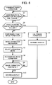
will be described in reference to FIG. 6.
Firstly, the detection device detects the number of rotations
and torque of the photoreceptor and the developing roller, and
checks for any abnormality in the number of rotations and torque
(S1). If an abnormality is found, a check is made to determine
whether or not the paper has already been fed as far as the pair
of registration rollers 45 (S2). If the paper has reached the pair
of registration rollers 45 (S2 YES), since preparations for
operation of the image formation unit have commenced, image
formation operation is halted (S3), a warning notifying occurrence
of an abnormality is displayed on the display unit 90 (S4), and
operation completed. On the other hand, if the paper has not yet
reached the pair of registration rollers 45 (S2 NO), image
formation operation is halted temporarily (S5), the separation
mechanism 210 is driven, and the image formation unit on the side
wherein the abnormality occurred is separated from the
intermediate transfer belt (S6). When the image formation unit
on the side wherein the abnormality occurred is separated from the
intermediate transfer belt, the control part switches to the
temporary operating mode wherein images are formed on the paper
using only the image formation unit having the required functions
(S7). Image formation operation is then resumed (S8), and image
formation in the temporary operating mode wherein images are formed
on the paper using only the image formation unit having the required
functions is executed (S8). When the formation of the prescribed
number of images is complete, (S9 YES), a warning notifying
occurrence of an abnormality is displayed on the display unit 90
(S10) and operation is completed.
In this manner, the image formation mode may be switched
during image formation operation, and halting of the apparatus due
to an error and the like during image formation operation can be
suppressed. As a result, following restoration [of normal
operation], the trouble involved in forming the same image again
and the like can be reduced.
Since only the K color image formation unit is used in the
monochrome mode, even if the Y, M, and C color image formation units
do not have the required functions, double-faced copying using the
K color first image formation unit 80K and the K color second image
formation unit 81K is possible. Therefore, even if the Y, M, and
C color image formation units do not have the required functions,
in the monochrome mode, double-faced copying using the first image
formation units and the second image formation units may be made
possible.
Next, control during double-faced image formation operation
will be described in reference to FIG. 7.
As shown in FIG. 7, when double-faced image formation
operation is commenced, a check is made to determine whether or
not there is an error in the image formation unit (S1). If no error
is found in any of the image formation units (S1 NO), the first
image formation units and the second image formation units are used
in executing the normal operating mode for double-faced image
formation (S4). On the other hand, if an error occurs in an image
formation unit (S1 NO), a check [is made] to determine whether or
not the monochrome mode is selected (S2). In the monochrome mode
(S2 YES) , a check is made to determine whether or not there is an
error in the K color image formation unit (S3). If no error is
found in either the K color first image formation unit or the K
color second image formation unit (S3 NO), double-faced image
formation is conducted in the normal operating mode (S4). On the
other hand, in other than the monochrome mode (S2 NO), and when
an error occurs in one of the K color image formation units (S3
YES), the temporary operating mode wherein double-faced image
formation is conducted with an image formation unit having the
required functions is executed (S5).
According to the present embodiment, when the first image
formation units 80K through 80Y and the second image formation
units 81K through 81Y have the required functions, the image is
created on one face of the paper with the first image formation
units. Furthermore, the image is created on the other face of the
paper with the second image formation units. The image created
with the first image formation units is transferred from the first
intermediate transfer belt 21 to one face of the paper, and the
image created with the second image formation units is transferred
from the second intermediate transfer belt 31 to the other face
of the paper. Thus, the image can be created at high-speed on both
faces of the paper. On the other hand, if either the first image
formation units 80K through 80Y and the second image formation
units 81K through 81Y does not have the required functions due to
a fault and the like, the image is formed on both faces of the paper
using only the image formation unit having the required functions.
The image is created on one face of the paper with the image
formation unit having the required functions, and this image is
transferred from one intermediate transfer belt to the other
intermediate transfer belt. Next, the image on the other face of
the paper is formed with the image formation unit having the
required functions, and transferred to the intermediate transfer
belt. Thus, the image is transferred from one intermediate
transfer belt to one face of the paper, and the image is transferred
from the other intermediate transfer belt to the other face of the
paper. In this manner, the image can be formed on both faces of
the paper even if one image formation unit does not have the
required functions due to a fault and the like.
Furthermore, in the present embodiment, a check is made to
determine whether or not the first image formation units 80k
through 80Y and the second image formation units 81K through 81Y
have the required functions. If, as a result of the check, it is
evaluated that one of the image formation units does not have the
required functions, the image formation method is switched to the
method of forming the image on both faces of the paper using only
the image formation unit having the required functions. Thus, the
image can be formed on both faces of the paper even if one image
formation unit does not have the required functions due to a fault
and the like.
Furthermore, in the present embodiment, a separation device
mutually separating the image formation unit which does not have
the required functions from the intermediate transfer body is
provided as a separation mechanism. Thus, the problem of the image
formation unit which does not have the required functions rubbing
the toner image on the intermediate transfer belt and disturbing
the image can be prevented.
Furthermore, the first secondary transfer roller 46 is
provided on the inner periphery of the second intermediate transfer
belt 31, and the second secondary transfer roller 47 is provided
on the inner periphery of the first intermediate transfer belt 21.
Thus, the secondary transfer rollers 46 and 47 are not contaminated
by toner scattered during transfer to the paper and intermediate
transfer belts. Occurrence of an abnormal image due to transfer
defects can therefore be suppressed.
Furthermore, transfer bias is applied with the secondary
transfer rollers 46 and 47 in contact with the intermediate
transfer belts 21 and 31. Thus, electrical discharge does not occur
suppressing the generation of ozone, and an
environmentally-friendly image formation apparatus can be
obtained.
Furthermore, since bias is applied to the secondary transfer
rollers 46 and 47 and transfer conducted, the image can be reliably
transferred.
Furthermore, in the present embodiment, part of the first
intermediate transfer belt 21 and part of the second intermediate
transfer belt 31 are positioned opposite each other to constitute
the secondary transfer nip. Thus, the image can be transferred
from one intermediate transfer belt to the other intermediate
transfer belt within this secondary transfer nip. Furthermore,
the paper is fed to this secondary transfer nip and the image on
the first intermediate transfer belt 21 is transferred to one face
of the paper, and the image on the second intermediate transfer
belt 31 is transferred to the other face of the paper. Thus, an
image can be formed on both faces of the paper without [the need
for] switch-back of the paper. Image formation time is therefore
shorter than with double-faced image formation using switch-back.
Furthermore, since a mirror image of the manuscript image is
created with the image formation unit for the tertiary transfer
image transferred from the image formation unit to the intermediate
transfer belt, transferred from this intermediate transfer belt
to the other intermediate transfer belt, and then transferred to
the paper, the image transferred to the paper is not reversed.
Furthermore, in the present embodiment, the transfer current
flowing when the image is transferred from one intermediate
transfer belt to the other intermediate transfer belt is controlled
so that it is less than the transfer current flowing when the image
is transferred from the intermediate transfer belt to the paper.
Thus, the occurrence of leaks and the like is suppressed, and a
satisfactory image can be formed.
Furthermore, the image formation unit is controlled so that
toner density when the tertiary transfer image transferred between
the first intermediate transfer belt 21 and the second intermediate
transfer belt 31 and then to the paper is formed with the image
formation unit is greater than when the secondary transfer image
transferred to the paper without transfer between the intermediate
transfer belts is formed. Thus, the density of the image on both
faces of the paper can be made the same.
Furthermore, the leading edge of the image on the first
intermediate transfer belt 21 and the leading edge of the image
on the second intermediate transfer belt 31 are fed simultaneously
to the secondary transfer nip. Thus, the image can be transferred
to the front and rear of the paper without slippage.
In the present embodiment, even if it is detected that either
the first image formation units or the second image formation units
do not have the required functions, if the first image formation
unit 80K used when forming a specific image (monochrome image),
and the second image formation unit 81K used when forming a specific
image (monochrome image) have the required functions, both the
first image formation unit 80K and the second image formation unit
81K are used to form the image on both faces of the paper in the
normal operating mode. Thus, even if at least one image formation
unit does not have the required functions, if the image formation
units 80K and 81K used in forming the specific image (monochrome
image) have the required functions [the image] can be formed in
the normal operating mode. Thus, the specific image (monochrome
image) can be processed without reducing the image formation speed.
Furthermore, the afore-mentioned specific image is not
limited to a monochrome image, and for example, images in other
basic colors (Y, M, C), and images in two colors such as K and M,
may be [formed].
As described above, according to the present embodiment, if
it is detected that the first image formation units or the second
image formation units do not have the required functions due to
a fault and the like, the first image and second image are formed
with the image formation unit having the required functions, and
the method of forming images on both faces of the recording medium
is selected. Thus, even if the prescribed operation is not possible
due to a fault and the like in the first image formation units or
the second image formation units, this has the effect of allowing
formation of the image on both faces of the recording medium.
Various modifications will become possible for those skilled
in the art after receiving the teaching of the present disclosure
without departing from the scope thereof.