US6445895B2 - Image forming apparatus having a belt attaching/detaching mechanism - Google Patents
Image forming apparatus having a belt attaching/detaching mechanism Download PDFInfo
- Publication number
- US6445895B2 US6445895B2 US09/768,810 US76881001A US6445895B2 US 6445895 B2 US6445895 B2 US 6445895B2 US 76881001 A US76881001 A US 76881001A US 6445895 B2 US6445895 B2 US 6445895B2
- Authority
- US
- United States
- Prior art keywords
- belt
- tension
- image forming
- forming apparatus
- attachment
- Prior art date
- Legal status (The legal status is an assumption and is not a legal conclusion. Google has not performed a legal analysis and makes no representation as to the accuracy of the status listed.)
- Expired - Lifetime
Links
Images


Classifications
-
- G—PHYSICS
- G03—PHOTOGRAPHY; CINEMATOGRAPHY; ANALOGOUS TECHNIQUES USING WAVES OTHER THAN OPTICAL WAVES; ELECTROGRAPHY; HOLOGRAPHY
- G03G—ELECTROGRAPHY; ELECTROPHOTOGRAPHY; MAGNETOGRAPHY
- G03G15/00—Apparatus for electrographic processes using a charge pattern
- G03G15/75—Details relating to xerographic drum, band or plate, e.g. replacing, testing
- G03G15/754—Details relating to xerographic drum, band or plate, e.g. replacing, testing relating to band, e.g. tensioning
-
- G—PHYSICS
- G03—PHOTOGRAPHY; CINEMATOGRAPHY; ANALOGOUS TECHNIQUES USING WAVES OTHER THAN OPTICAL WAVES; ELECTROGRAPHY; HOLOGRAPHY
- G03G—ELECTROGRAPHY; ELECTROPHOTOGRAPHY; MAGNETOGRAPHY
- G03G15/00—Apparatus for electrographic processes using a charge pattern
- G03G15/14—Apparatus for electrographic processes using a charge pattern for transferring a pattern to a second base
- G03G15/16—Apparatus for electrographic processes using a charge pattern for transferring a pattern to a second base of a toner pattern, e.g. a powder pattern, e.g. magnetic transfer
- G03G15/1605—Apparatus for electrographic processes using a charge pattern for transferring a pattern to a second base of a toner pattern, e.g. a powder pattern, e.g. magnetic transfer using at least one intermediate support
- G03G15/1615—Apparatus for electrographic processes using a charge pattern for transferring a pattern to a second base of a toner pattern, e.g. a powder pattern, e.g. magnetic transfer using at least one intermediate support relating to the driving mechanism for the intermediate support, e.g. gears, couplings, belt tensioning
-
- G—PHYSICS
- G03—PHOTOGRAPHY; CINEMATOGRAPHY; ANALOGOUS TECHNIQUES USING WAVES OTHER THAN OPTICAL WAVES; ELECTROGRAPHY; HOLOGRAPHY
- G03G—ELECTROGRAPHY; ELECTROPHOTOGRAPHY; MAGNETOGRAPHY
- G03G2215/00—Apparatus for electrophotographic processes
- G03G2215/00135—Handling of parts of the apparatus
- G03G2215/00139—Belt
- G03G2215/00143—Meandering prevention
- G03G2215/00156—Meandering prevention by controlling drive mechanism
-
- G—PHYSICS
- G03—PHOTOGRAPHY; CINEMATOGRAPHY; ANALOGOUS TECHNIQUES USING WAVES OTHER THAN OPTICAL WAVES; ELECTROGRAPHY; HOLOGRAPHY
- G03G—ELECTROGRAPHY; ELECTROPHOTOGRAPHY; MAGNETOGRAPHY
- G03G2215/00—Apparatus for electrophotographic processes
- G03G2215/01—Apparatus for electrophotographic processes for producing multicoloured copies
- G03G2215/019—Structural features of the multicolour image forming apparatus
- G03G2215/0193—Structural features of the multicolour image forming apparatus transfer member separable from recording member
-
- G—PHYSICS
- G03—PHOTOGRAPHY; CINEMATOGRAPHY; ANALOGOUS TECHNIQUES USING WAVES OTHER THAN OPTICAL WAVES; ELECTROGRAPHY; HOLOGRAPHY
- G03G—ELECTROGRAPHY; ELECTROPHOTOGRAPHY; MAGNETOGRAPHY
- G03G2221/00—Processes not provided for by group G03G2215/00, e.g. cleaning or residual charge elimination
- G03G2221/16—Mechanical means for facilitating the maintenance of the apparatus, e.g. modular arrangements and complete machine concepts
- G03G2221/1606—Mechanical means for facilitating the maintenance of the apparatus, e.g. modular arrangements and complete machine concepts for the photosensitive element
Definitions
- the present invention relates to an image forming apparatus such as an apparatus of the electrophotographic type, for example, a copier, a printer, or a facsimile apparatus, and particularly to a belt cartridge attaching and detaching mechanism for accommodating and replacing a belt.
- the belt which is to be replaced includes: a photosensitive belt on which an electrostatic latent image is to be formed; an intermediate transfer belt which once retains a toner image formed on a photosensitive member and then transfers the image onto a transfer member; and a transfer medium transport belt which transports such a transfer member.
- an electrostatic latent image is written in the surface of a drum-like or belt-like photosensitive member which is uniformly charged, and the electrostatic latent image is developed by a toner.
- the toner image on the photosensitive member is directly transferred to a transfer medium such as a copy sheet, or the toner image on the photosensitive member is primary-transferred to an intermediate transfer belt and the transferred toner image is secondary-transferred to a transfer medium, so that a so-called hard copy of an image is obtained.
- the photosensitive belt, the intermediate transfer belt, and the transfer medium transport belt are worn in accordance with the use condition and deterioration with time, and therefore must be periodically replaced with a new one.
- JP-A-8-123294 discloses a method wherein shafts between which a belt is stretched are movably configured so that replacement of the belt only can be performed.
- JP-A-57-60356 discloses a method in which a restricting member is disposed in the vicinity of an end of a roller to prevent a belt from meandering.
- a restricting member is disposed in the vicinity of an end of a roller to prevent a belt from meandering.
- JP-A-4-133926 discloses a method in which a tapered ring is coupled with the shaft of a steering roller, and the steering roller is tilted in accordance with a force which is produced by meandering of a belt to cause the tapered ring to be forcedly rotated, thereby correcting meandering.
- the invention provides an image forming apparatus in which a belt cartridge incorporating a belt and plural rolls that support the belt is detachably mounted in a main unit of the image forming apparatus to enable the belt to be replaced, wherein at least one of the plural rolls is a tension roller in which a rotation shaft is movable in a direction along which predetermined tension is applied to the belt,
- the belt cartridge comprises an attachment/detachment guide pin which is used in attachment to and detachment from the main unit of the image forming apparatus
- the main unit of the image forming apparatus comprises a belt tension applying mechanism which moves the tension roller to apply predetermined tension to the belt, and a guide groove which is used in attachment and detachment of the belt cartridge, and in attachment of the belt cartridge, the attachment/detachment guide pin is guided by the attachment/detachment guide groove, and the belt tension applying mechanism is engaged with the rotation shaft of the tension roller to apply the predetermined tension to the belt.
- the belt tension applying mechanism which moves the tension roller to apply predetermined tension to the belt, and the guide groove which is used in attachment and detachment of the belt cartridge are disposed on the side of the main unit of the image forming apparatus.
- the belt cartridge is of the disposal type, therefore, it is not required to dispose many gears and clutches in the belt cartridge, and hence the number of parts to be junked together with other components is largely reduced. Therefore, it is possible to obtain a structure which is preferable and economical from both the viewpoints of saving of resources and the cost.
- the structure of the belt cartridge is simplified so that works of recycling and checking require little time period and man power.
- the invention provides an image forming apparatus in which a belt is singly attachable to and detachable from the plural belt support rolls, wherein at least one of the plural rolls is a tension roller in which a rotation shaft is movable in a direction along which predetermined tension is applied to the belt, a main unit of the image forming apparatus comprises a belt tension applying mechanism which moves the tension roller to apply the predetermined tension to the belt, and in attachment of the belt, the belt tension applying mechanism is engaged with the rotation shaft of the tension roller to apply the predetermined tension to the belt.
- the belt tension applying mechanism which moves the tension roller to apply predetermined tension to the belt is disposed on the side of the main unit of the image forming apparatus. Therefore, mechanism in a region enclosed by the belt has a simplified structure, whereby cumbersome in checking of the mechanism in the narrow region can be eliminated.
- the apparatus comprises: a meandering detecting sensor for the belt; and a belt meandering correcting mechanism which, based on a detection result of the meandering detecting sensor, drives the belt tension applying mechanism to correct meandering.
- meandering of the belt can be automatically corrected in a sufficient manner even when the degree of meandering is changed during operation or the ability of correcting meandering becomes in sufficient owing to deterioration with time.
- the belt may be either of a photosensitive belt, an intermediate transfer belt, and a transfer medium transport belt.
- FIG. 1 is a view schematically showing the structure of a color laser printer which is Embodiment 1 of the image forming apparatus according to the invention
- FIG. 2 is a view schematically showing the internal configuration of a photosensitive belt cartridge 12 ;
- FIG. 3 is a view showing a state where attachment/detachment guide pins 10 and 11 of the photosensitive belt cartridge 12 enter attachment/detachment guide grooves 31 and 30 of the main unit of the image forming apparatus, respectively;
- FIG. 4 is a view showing an example of the shapes of attachment/detachment guide grooves 30 , 31 , and 32 which are formed in a frame 29 of the main unit of the image forming apparatus;
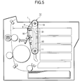
- FIG. 5 is a view showing procedure 1 of attaching the photosensitive belt cartridge
- FIG. 6 is a view showing procedure 2 of attaching the photosensitive belt cartridge
- FIG. 7 is a view showing procedure 3 of attaching the photosensitive belt cartridge
- FIG. 8 is a view showing the configuration of Embodiment 2 of the image forming apparatus according to the invention.
- FIG. 9 is a block diagram showing an example of the configuration of a meandering correction control system for a photosensitive belt 1 ;
- FIG. 10 is a view schematically showing the structure of a color laser printer using an intermediate transfer belt cartridge and a photosensitive body.
- FIG. 11 is a view schematically showing the structure of a laser printer using a transfer medium transport belt cartridge and a photosensitive body.
- FIG. 1 is a view schematically showing the structure of a color laser printer which is Embodiment 1 of the image forming apparatus of the electrophotographic type according to the invention.
- a photosensitive belt cartridge 12 is shown in a state where the cartridge is attached with being guided by attachment/detachment guide pins 10 and 11 .
- Predetermined tension is applied to a photosensitive belt (see FIG. 2) by a belt tension applying mechanism including a tension link 13 , a stopper guide 14 , and a spring 15 .
- the photosensitive belt (see FIG. 2) which is accommodated in the photosensitive belt cartridge 12 is charged by a charger 23 , and exposed to image light by a laser writing unit 24 on the basis of image data sent from a personal computer or the like which is not shown, and retains an electrostatic latent image.
- Developing units 25 , 26 , 27 , and 28 respectively contain developing agents of different colors, for example, yellow, magenta, cyan, and black, and are arranged so as to be opposed to the photosensitive belt cartridge 12 .
- the developing units 25 to 28 develop the electrostatic latent image on the exposed photosensitive belt 1 by the non-contact developing method.
- the developed image is transferred from the photosensitive belt 1 to an intermediate transfer belt 19 , to be retained thereon in a state where the colors are superimposed with one another.
- transfer media such as copy sheets which are accommodated in a sheet supply cassette 22 are separated into individual ones by a separation roller 21 .
- Each transfer medium is passed over a transport roller 20 and then supplied between the intermediate transfer belt 19 and a backup roller 18 .
- the backup roller 18 cooperates with the intermediate transfer belt 19 to electrostatically transfer the toner image formed on the intermediate transfer belt 19 , to the transfer medium.
- the image is fixed by a fixing roller 17 to the transfer medium to which the image has been electrostatically transferred.
- the transfer medium is then discharged by a transport roller 16 onto the upper face of the main unit of the apparatus.
- an upper cover 38 is rotated in a counterclockwise direction about a fulcrum 39 so as to be largely opened. Therefore, attachment or detachment of the photosensitive belt cartridge 12 , and maintenance of the interior of the apparatus main unit can be conveniently performed.
- the invention has been described with taking a color laser printer as an example. Therefore, the printer has the plural developing units 25 , 26 , 27 , and 28 . In the invention, the number of developing units is not restricted. Therefore, the invention can be applied also to a monochrome laser printer, etc.
- FIG. 2 is a view schematically showing the internal configuration of the photosensitive belt cartridge 12 .
- the photosensitive belt cartridge 12 is configured by the photosensitive belt 1 , a driving roller 2 , a driven roller 3 , a tension roller 4 , guide rollers 5 , 6 , and 7 , a frame 8 which holds rotation shafts of these rollers, a guide groove 9 which movably holds the rotation shaft of the tension roller 4 , and attachment/detachment guide pins 10 and 11 .
- the photosensitive belt 1 on which an electrostatic latent image is to be formed is stretched among the driving roller 2 , the driven roller 3 , and the tension roller 4 for applying predetermined tension to the photosensitive belt 1 .
- the belt is driven in a counterclockwise direction.
- the rotation shafts of the guide rollers 5 , 6 , and 7 are fixed to the frame 8 , and are in contact with the inner periphery of the photosensitive belt 1 to guide the belt.
- the rotation shaft of the tension roller 4 is movable along the guide groove 9 formed in the frame 8 , in a substantially horizontal direction in the figure.
- the attachment/detachment guide pins 10 and 11 restrict the position of the photosensitive belt cartridge 12 .
- FIG. 3 is a view of a left end portion of the photosensitive belt cartridge 12 as seen from the front side, and showing a state where the attachment/detachment guide pins 10 and 11 of the photosensitive belt cartridge 12 enter attachment/detachment guide grooves 31 and 30 of the main unit of the image forming apparatus, respectively.
- the photosensitive belt cartridge 12 comprises the lateral pair of attachment/detachment guide pins 10 and 11 which are coaxial with the driving roller 2 and the driven roller 3 , respectively.
- the attachment/detachment guide pins 10 and 11 are attached at different positions in the width direction, and enter the attachment/detachment guide grooves 31 and 30 which are formed at different positions in the width direction of a frame 29 of the main unit of the image forming apparatus, respectively.
- FIG. 4 is a view showing an example of the shapes of attachment/detachment guide grooves 30 , 31 , and 32 which are formed in the frame 29 of the main unit of the image forming apparatus.
- the attachment/detachment guide grooves 30 , 31 , and 32 which are disposed in the side frame 29 of the main unit of the image forming apparatus have a shape in which a vertical groove portion is combined with an obliquely downward groove portion.
- the main unit of the image forming apparatus is configured so that, when the upper cover 38 is rotated in a counterclockwise direction about the fulcrum 39 , the upper portion of the main unit of the image forming apparatus is largely opened. In this state, the photosensitive belt cartridge 12 is attached or detached.
- the photosensitive belt cartridge 12 is inserted so that the attachment/detachment guide pin 11 is moved along the attachment/detachment guide groove 30 .
- the rotation shaft of the tension roller 4 which is movable along the guide groove 9 abuts against an upper portion of the attachment/detachment guide groove 32 which is widened in a tapered manner.
- the shaft is pushed more leftward in the figure.
- the attachment/detachment guide pin 10 is inserted into the attachment/detachment guide groove 31 .
- the rotation shaft of the tension roller 4 is engaged with the notch of the tension link 13 to press down the tension link 13 .
- the spring 15 is extended, and the tension link 13 is pulled by the tensile spring force to apply tension to the belt 1 .
- the rotation shafts of the attachment/detachment guide pins 10 and 11 and the tension roller 4 reach the respective obliquely downward groove portions of the attachment/detachment guide grooves 30 , 31 , and 32 , and the photosensitive belt cartridge 12 is obliquely downward lowered in accordance with the shapes of the attachment/detachment guide grooves 30 , 31 , and 32 .
- the cartridge is held at the position shown in FIG. 7 .
- the tension roller 4 is further pulled out by the tension link 13 , so that predetermined tension which is suitable for belt driving is applied to the photosensitive belt 1 .
- a driving gear of the driving roller 2 which is coaxial with the attachment/detachment guide pin 10 meshes with a gear of a power unit of the main unit of the image forming apparatus, thereby completing attachment of the photosensitive belt cartridge 12 to the main unit of the image forming apparatus.
- the photosensitive belt cartridge 12 is locked by a releasable lock lever which is automatically engaged therewith after attachment to the main unit of the image forming apparatus, to be restricted to a predetermined position, whereby the meshing state of the gears is maintained.
- the method of taking out the photosensitive belt cartridge 12 from the main unit of the image forming apparatus is performed in a sequence opposite to that of the attachment. Namely, when the photosensitive belt cartridge 12 is pulled up, the cartridge can be easily taken out from the main unit of the image forming apparatus.
- Data of a color image are calculated by using a personal computer or the like to produce image data of each color.
- the image data are input to the image forming apparatus of FIG. 1 .
- a laser beam which is generated by a semiconductor laser of the laser writing unit 24 is projected to the peripheral face of the photosensitive belt 1 that has been uniformly charged by the charger 23 , thereby forming a bright line.
- the beam When scanning is started, the beam is detected by an index sensor, beam modulation due to a first color signal is started, and the peripheral face of the photosensitive belt 1 is scanned by the modulated beam. In accordance with the main scanning due to the laser beam and the sub scanning due to transportation of the photosensitive belt 1 , therefore, a latent image corresponding to the first color is formed in the peripheral face of the photosensitive belt 1 .
- the latent image is developed by one of developing means, i.e., the developing unit 28 which is filled with a toner (developing medium) of yellow (Y), to be formed as a toner image on the surface of the photosensitive belt 1 .
- developing means i.e., the developing unit 28 which is filled with a toner (developing medium) of yellow (Y), to be formed as a toner image on the surface of the photosensitive belt 1 .
- the obtained toner image is transported to the intermediate transfer belt 19 while being retained to the surface of the photosensitive belt 1 , and then transferred to the intermediate transfer belt 19 .
- the photosensitive belt 1 is again uniformly changed by the charger 23 , and a second color signal output from a signal processing section is input to the laser writing unit 24 .
- writing is performed on the surface of the photosensitive belt to form a latent image.
- the latent image is developed by the developing unit 27 which is filled with a toner of a second color or magenta (M).
- the toner image of magenta (M) is transferred to the intermediate transfer belt 19 to be superimposed to the toner image of yellow (Y) which has been already formed.
- a toner image of cyan (C) is formed by the developing unit 26 which is filled with a toner of cyan (C), and then transferred, and a toner image of black is formed by the developing unit 25 which is filled with a toner of black, to be superimposed on the intermediate transfer belt 19 , thereby forming a color toner image.
- the color toner image which is formed on the peripheral face of the intermediate transfer belt 19 is transferred to a transfer medium.
- Transfer media are sent one by one into a sheet supply path by means of friction with a sheet supply roller 21 , from the sheet supply cassette 22 below the developing units 25 to 28 , passed over the transport roller 20 , and then supplied to the intermediate transfer belt 19 with making the passing timing of the forward end of the transfer medium coincident with the image formation position on the intermediate transfer belt 19 .
- the transfer medium which has been supplied to the intermediate transfer belt 19 and to which the image has been transferred is subjected to fusion and fixation of the image by the fixing roller 17 , passed over a discharge roller 16 , and then discharged to a discharge tray to be stacked thereon.
- the color image can be printed out at a desired number.
- FIG. 8 is a view schematically showing the configuration of Embodiment 2 of the image forming apparatus according to the invention.
- Embodiment 2 is an example in which the image forming apparatus of Embodiment 1 is modified so as to further comprise a meandering detecting sensor for the belt, and a belt meandering correcting mechanism which, based on a detection result of the meandering detecting sensor, drives the belt tension applying mechanism to correct meandering.
- the meandering detecting sensor 37 detects an unbalanced state of the photosensitive belt 1 in the photosensitive belt cartridge 12 .
- a CCD linear array sensor is used as the meandering detecting sensor.
- a laser displacement detecting sensor, an ultrasonic distance sensor, a two-dimensional CCD cameral sensor, or the like may be used.
- the belt meandering correcting mechanism 33 includes a stage driving gear 34 and a meandering control motor 35 .
- FIG. 9 is a block diagram showing an example of the configuration of a meandering correction control system for the photosensitive belt 1 .
- a motor control device 40 calculates the direction and degree of meandering of the photosensitive belt 1 based on an unbalance detection signal supplied from the meandering detecting sensor 37 , and, on the basis of the calculated meandering direction and degree, outputs a rotation direction signal and a rotation angle signal to the meandering control motor 35 in the belt meandering correcting mechanism 33 .
- command values for the direction and degree of meandering of the photosensitive belt 1 are calculated.
- the rotation direction of the meandering control motor 35 is switched over, and, when the meandering degree is not 0, the rotation angle signal corresponding to the meandering degree is output.
- the meandering control motor 35 drives the linear stage 36 via the stage driving gear 34 .
- the spring force is changed.
- the spring force of the spring 15 acts on the photosensitive belt 1 via the tension link 13 and the tension roller 4 to adjust the lateral tension of the photosensitive belt 1 , thereby adjusting the unbalance of the belt.
- the image can be accurately formed and color toners can be correctly placed, so that an output image of high quality can be obtained.
- the structure in which the spring 15 is extended and contracted is employed.
- the spring 15 may not be used, and the linear stage 36 may directly drive the tension link 13 to control the lateral tension of the photosensitive belt 1 .
- a mechanism which uses friction may be used as the meandering detecting mechanism, and the tension link 13 is moved by means of friction.
- the embodiments using a photosensitive belt cartridge have been described.
- the invention may be applied also to an image forming apparatus using an intermediate transfer belt cartridge in which the belt is an intermediate transfer belt, or a transfer medium transport belt cartridge in which the belt is a transfer medium transport belt.
- FIG. 10 shows the structure of a color laser printer using an intermediate transfer belt cartridge 43 and a photosensitive body 44 which is another embodiment of the image forming apparatus.
- the intermediate transfer belt cartridge 43 has a transfer unit 41 and an intermediate transfer belt 43 .
- FIG. 11 shows the structure of a laser printer using a transfer medium transport belt cartridge 48 and a photosensitive body 44 which is another embodiment of the image forming apparatus.
- the intermediate transfer belt cartridge 43 and the transfer medium transport belt cartridge 48 have the same attachment/detachment structure as that of the photosensitive belt cartridge 12 shown in FIG. 1 . Further, a belt tension giving mechanism and the attachment/detachment groove at the printer body side shown in FIGS. 10 and 11 also have the same structures as those shown in FIG. 1 .
- the image forming apparatuses in which a belt cartridge is employed have been described.
- the belt tension applying mechanism and the belt meandering correcting mechanism in the invention may be applied also to an image forming apparatus in which a belt cartridge is not used and replacement of a belt only is enabled, in the following manner.
- FIG. 1 A description will be made with reference to the configuration of FIG. 1 .
- the spring 15 is detached from the tension link 13 , the tension link 13 is disconnected from the shaft of the tension roller 4 , and the tension link 13 is retracted to a position where the link does not interfere with the belt.
- the shaft of the tension roller 4 is moved, and the application of tension on the photosensitive belt 1 is canceled, so that the belt can be easily replaced.
- various belts constituting an image forming apparatus such as a photosensitive belt, an intermediate transfer belt, and a transfer medium transport belt can be easily replaced in the form of a belt cartridge with new one. Furthermore, constituting members can be individually driven by a driving device of the main unit of the image forming apparatus. Therefore, a belt cartridge in which the number of components to be replaced together with the belt is reduced, and an image forming apparatus using such a belt cartridge can be provided.
- an image forming apparatus can be provided in which various belts constituting the image forming apparatus, such as a photosensitive belt, an intermediate transfer belt, and a transfer medium transport belt can be easily replaced in the form of a belt cartridge with new one, and in which unbalance of such a belt can be corrected, and transportation which is correct and stable is enabled.
- various belts constituting the image forming apparatus such as a photosensitive belt, an intermediate transfer belt, and a transfer medium transport belt can be easily replaced in the form of a belt cartridge with new one, and in which unbalance of such a belt can be corrected, and transportation which is correct and stable is enabled.
Landscapes
- Physics & Mathematics (AREA)
- General Physics & Mathematics (AREA)
- Electrophotography Configuration And Component (AREA)
- Discharging, Photosensitive Material Shape In Electrophotography (AREA)
- Electrostatic Charge, Transfer And Separation In Electrography (AREA)
Abstract
Description
Claims (7)
Applications Claiming Priority (2)
| Application Number | Priority Date | Filing Date | Title |
|---|---|---|---|
| JP2000-015466 | 2000-01-25 | ||
| JP2000015466A JP2001209294A (en) | 2000-01-25 | 2000-01-25 | Image forming device |
Publications (2)
| Publication Number | Publication Date |
|---|---|
| US20010022903A1 US20010022903A1 (en) | 2001-09-20 |
| US6445895B2 true US6445895B2 (en) | 2002-09-03 |
Family
ID=18542765
Family Applications (1)
| Application Number | Title | Priority Date | Filing Date |
|---|---|---|---|
| US09/768,810 Expired - Lifetime US6445895B2 (en) | 2000-01-25 | 2001-01-25 | Image forming apparatus having a belt attaching/detaching mechanism |
Country Status (2)
| Country | Link |
|---|---|
| US (1) | US6445895B2 (en) |
| JP (1) | JP2001209294A (en) |
Cited By (16)
| Publication number | Priority date | Publication date | Assignee | Title |
|---|---|---|---|---|
| US6584289B2 (en) * | 2001-06-04 | 2003-06-24 | Heidelberger Druckmaschinen Ag | Method and apparatus for setting transfer roller engagement |
| US20050002693A1 (en) * | 2003-07-02 | 2005-01-06 | Samsung Electronics Co., Ltd. | Automatic belt tension apparatus of image forming device |
| US20050095018A1 (en) * | 2003-10-31 | 2005-05-05 | Byeong-Hwa Ahn | Image forming apparatus |
| US20050231821A1 (en) * | 2004-03-31 | 2005-10-20 | Masaaki Tsuda | Unit supporting device and image forming apparatus |
| US20050254857A1 (en) * | 2004-05-14 | 2005-11-17 | Samsung Electronics Co., Ltd. | Tension adjuster of belt of image forming apparatus |
| US20060110182A1 (en) * | 2004-11-22 | 2006-05-25 | Samsung Electronics Co., Ltd. | Image forming apparatus including photosensitive body fixing apparatus |
| US20070009310A1 (en) * | 2005-06-29 | 2007-01-11 | Brother Kogyo Kabushiki Kaisha | Image forming device |
| US20070025762A1 (en) * | 2005-07-26 | 2007-02-01 | Brother Kogyo Kabushiki Kaisha | Image forming apparatus |
| US20070248377A1 (en) * | 2006-04-19 | 2007-10-25 | Lexmark International, Inc. | Architecture for an image-forming device |
| US20070247511A1 (en) * | 2006-04-19 | 2007-10-25 | Lexmark International, Inc. | Architectures for multi-functional image forming devices |
| US7454158B2 (en) | 2005-08-25 | 2008-11-18 | Brother Kogyo Kabushiki Kaisha | Image forming apparatus with accommodation spaces |
| US20090180805A1 (en) * | 2007-12-17 | 2009-07-16 | Makoto Nakura | Belt device and image forming apparatus |
| US20110078320A1 (en) * | 2006-06-28 | 2011-03-31 | Cisco Technology, Inc. | Application integrated gateway |
| US7986911B2 (en) | 2007-03-28 | 2011-07-26 | Lexmark International, Inc. | Architecture for a media feeding option for an image forming device |
| US20130016983A1 (en) * | 2011-07-11 | 2013-01-17 | Canon Kabushiki Kaisha | Image forming apparatus |
| US20130216260A1 (en) * | 2012-02-21 | 2013-08-22 | Seiichi Kogure | Image forming apparatus |
Families Citing this family (15)
| Publication number | Priority date | Publication date | Assignee | Title |
|---|---|---|---|---|
| US20050053395A1 (en) * | 2003-09-04 | 2005-03-10 | Xerox Corporation | Photoreceptor module with retracting backer bars |
| JP2005292332A (en) * | 2004-03-31 | 2005-10-20 | Murata Mach Ltd | Image forming apparatus |
| JP4493476B2 (en) * | 2004-11-22 | 2010-06-30 | 京セラミタ株式会社 | Belt drive |
| JP4581913B2 (en) * | 2005-08-25 | 2010-11-17 | ブラザー工業株式会社 | Image forming apparatus |
| JP4930675B2 (en) * | 2005-09-22 | 2012-05-16 | 富士ゼロックス株式会社 | Image forming apparatus |
| CN1983063B (en) * | 2005-12-07 | 2010-12-01 | 株式会社理光 | Image forming device capable of stabilizing belt motion in belt unit |
| JP4761131B2 (en) | 2005-12-26 | 2011-08-31 | ブラザー工業株式会社 | Image forming apparatus |
| US7920808B2 (en) * | 2007-08-31 | 2011-04-05 | Ricoh Company, Ltd. | Belt device and image-forming apparatus |
| JP2009169167A (en) * | 2008-01-17 | 2009-07-30 | Ricoh Co Ltd | Image forming apparatus |
| JP5326427B2 (en) * | 2008-08-25 | 2013-10-30 | コニカミノルタ株式会社 | Image forming apparatus |
| JP5678446B2 (en) * | 2010-03-16 | 2015-03-04 | 富士ゼロックス株式会社 | Image forming apparatus |
| JP6112781B2 (en) * | 2012-06-01 | 2017-04-12 | キヤノン株式会社 | Image forming apparatus |
| JP2012252367A (en) * | 2012-09-28 | 2012-12-20 | Ricoh Co Ltd | Image forming apparatus |
| JP7047632B2 (en) * | 2018-06-28 | 2022-04-05 | セイコーエプソン株式会社 | Inkjet printer and method of dividing inkjet printer |
| JP7691652B2 (en) * | 2020-10-21 | 2025-06-12 | 株式会社リコー | Belt device, fixing device and image forming apparatus |
Citations (6)
| Publication number | Priority date | Publication date | Assignee | Title |
|---|---|---|---|---|
| JPS5859462A (en) * | 1981-10-05 | 1983-04-08 | Ricoh Co Ltd | Image recording device |
| US4634264A (en) * | 1983-11-25 | 1987-01-06 | Ricoh Company, Ltd. | Photosensitive member of recording apparatus |
| JPS6227209A (en) * | 1985-07-24 | 1987-02-05 | Ricoh Co Ltd | Meandering motion corrector for endless belt |
| JPH09134107A (en) * | 1995-11-10 | 1997-05-20 | Minolta Co Ltd | Image forming device |
| JPH11119499A (en) * | 1997-10-15 | 1999-04-30 | Konica Corp | Belt photoreceptor cartridge |
| US5991575A (en) * | 1998-05-12 | 1999-11-23 | Oki Data Corporation | Belt unit |
-
2000
- 2000-01-25 JP JP2000015466A patent/JP2001209294A/en active Pending
-
2001
- 2001-01-25 US US09/768,810 patent/US6445895B2/en not_active Expired - Lifetime
Patent Citations (6)
| Publication number | Priority date | Publication date | Assignee | Title |
|---|---|---|---|---|
| JPS5859462A (en) * | 1981-10-05 | 1983-04-08 | Ricoh Co Ltd | Image recording device |
| US4634264A (en) * | 1983-11-25 | 1987-01-06 | Ricoh Company, Ltd. | Photosensitive member of recording apparatus |
| JPS6227209A (en) * | 1985-07-24 | 1987-02-05 | Ricoh Co Ltd | Meandering motion corrector for endless belt |
| JPH09134107A (en) * | 1995-11-10 | 1997-05-20 | Minolta Co Ltd | Image forming device |
| JPH11119499A (en) * | 1997-10-15 | 1999-04-30 | Konica Corp | Belt photoreceptor cartridge |
| US5991575A (en) * | 1998-05-12 | 1999-11-23 | Oki Data Corporation | Belt unit |
Cited By (30)
| Publication number | Priority date | Publication date | Assignee | Title |
|---|---|---|---|---|
| US6584289B2 (en) * | 2001-06-04 | 2003-06-24 | Heidelberger Druckmaschinen Ag | Method and apparatus for setting transfer roller engagement |
| US20050002693A1 (en) * | 2003-07-02 | 2005-01-06 | Samsung Electronics Co., Ltd. | Automatic belt tension apparatus of image forming device |
| US20060120757A1 (en) * | 2003-07-02 | 2006-06-08 | Samsung Electronics Co., Ltd. | Automatic belt tension apparatus of image forming device and method thereof |
| US7983599B2 (en) | 2003-07-02 | 2011-07-19 | Samsung Electronics Co., Ltd. | Automatic belt tension apparatus of image forming device and method thereof |
| US20050095018A1 (en) * | 2003-10-31 | 2005-05-05 | Byeong-Hwa Ahn | Image forming apparatus |
| US7218868B2 (en) * | 2003-10-31 | 2007-05-15 | Samsung Electronics Co., Ltd. | Image forming apparatus having locking/releasing unit |
| US7302208B2 (en) * | 2004-03-31 | 2007-11-27 | Ricoh Company, Limited | Unit supporting device and image forming apparatus |
| US20050231821A1 (en) * | 2004-03-31 | 2005-10-20 | Masaaki Tsuda | Unit supporting device and image forming apparatus |
| US20050254857A1 (en) * | 2004-05-14 | 2005-11-17 | Samsung Electronics Co., Ltd. | Tension adjuster of belt of image forming apparatus |
| US7359658B2 (en) * | 2004-05-14 | 2008-04-15 | Samsung Electronics Co., Ltd. | Tension adjuster of belt of image forming apparatus |
| US20060110182A1 (en) * | 2004-11-22 | 2006-05-25 | Samsung Electronics Co., Ltd. | Image forming apparatus including photosensitive body fixing apparatus |
| US7409176B2 (en) * | 2004-11-22 | 2008-08-05 | Samsung Electronics Co., Ltd. | Image forming apparatus including photosensitive body fixing apparatus |
| US20070009310A1 (en) * | 2005-06-29 | 2007-01-11 | Brother Kogyo Kabushiki Kaisha | Image forming device |
| US7347318B2 (en) | 2005-06-29 | 2008-03-25 | Brother Kogyo Kabushiki Kaisha | Image forming device |
| US7957672B2 (en) * | 2005-07-26 | 2011-06-07 | Brother Kogyo Kabushiki Kaisha | Image forming apparatus with a belt unit |
| US20070025762A1 (en) * | 2005-07-26 | 2007-02-01 | Brother Kogyo Kabushiki Kaisha | Image forming apparatus |
| US7454158B2 (en) | 2005-08-25 | 2008-11-18 | Brother Kogyo Kabushiki Kaisha | Image forming apparatus with accommodation spaces |
| US20070247511A1 (en) * | 2006-04-19 | 2007-10-25 | Lexmark International, Inc. | Architectures for multi-functional image forming devices |
| US20070248377A1 (en) * | 2006-04-19 | 2007-10-25 | Lexmark International, Inc. | Architecture for an image-forming device |
| US7639965B2 (en) | 2006-04-19 | 2009-12-29 | Lexmark International, Inc. | Architecture for an image-forming device |
| US7675536B2 (en) | 2006-04-19 | 2010-03-09 | Lexmark International, Inc. | Architectures for multi-functional image forming devices |
| US20110078320A1 (en) * | 2006-06-28 | 2011-03-31 | Cisco Technology, Inc. | Application integrated gateway |
| US7986911B2 (en) | 2007-03-28 | 2011-07-26 | Lexmark International, Inc. | Architecture for a media feeding option for an image forming device |
| US20090180805A1 (en) * | 2007-12-17 | 2009-07-16 | Makoto Nakura | Belt device and image forming apparatus |
| US8238793B2 (en) * | 2007-12-17 | 2012-08-07 | Ricoh Company, Limited | Belt device and image forming apparatus having a belt correcting unit and an adjusting unit |
| US8577261B2 (en) | 2007-12-17 | 2013-11-05 | Ricoh Company, Limited | Belt device and image forming apparatus |
| US20130016983A1 (en) * | 2011-07-11 | 2013-01-17 | Canon Kabushiki Kaisha | Image forming apparatus |
| US8879931B2 (en) * | 2011-07-11 | 2014-11-04 | Canon Kabushiki Kaisha | Image forming apparatus |
| US20130216260A1 (en) * | 2012-02-21 | 2013-08-22 | Seiichi Kogure | Image forming apparatus |
| US9042779B2 (en) * | 2012-02-21 | 2015-05-26 | Ricoh Company, Ltd. | Transfer belt device and image forming apparatus including the same |
Also Published As
| Publication number | Publication date |
|---|---|
| JP2001209294A (en) | 2001-08-03 |
| US20010022903A1 (en) | 2001-09-20 |
Similar Documents
| Publication | Publication Date | Title |
|---|---|---|
| US6445895B2 (en) | Image forming apparatus having a belt attaching/detaching mechanism | |
| US7643781B2 (en) | Transfer device and image forming apparatus | |
| JP2010114498A (en) | Image forming apparatus and image reading apparatus | |
| US6052552A (en) | Image forming apparatus with skew correction | |
| US7082282B2 (en) | Image formation method and image formation apparatus for same | |
| US7020431B2 (en) | Image forming apparatus with different transport speeds in transfer unit and fixing unit | |
| JP4850335B2 (en) | Image forming apparatus | |
| JP5039296B2 (en) | Image forming apparatus | |
| US20080123116A1 (en) | Image forming apparatus and image forming method | |
| JP5063273B2 (en) | Belt conveying apparatus and image forming apparatus | |
| JP3261095B2 (en) | Sheet conveying device and image forming apparatus provided with the sheet conveying device | |
| CN104813239A (en) | Unit assembly and image forming device | |
| JP2002040738A (en) | Image forming device | |
| JP3116168B2 (en) | Image forming device | |
| CN102122125B (en) | Transfer device | |
| JP5811441B2 (en) | Image forming apparatus and transfer unit | |
| JP3512307B2 (en) | Electrophotographic equipment | |
| JP5349262B2 (en) | Intermediate transfer belt conveying device, image forming apparatus and image forming method using the same | |
| JPH11295998A (en) | Image forming device | |
| JP4006384B2 (en) | Image forming apparatus | |
| US7079804B2 (en) | Image forming apparatus | |
| US20090129796A1 (en) | Image forming apparatus | |
| JP2004144918A (en) | Image forming device | |
| JP2008064819A (en) | Image forming apparatus | |
| US20250102973A1 (en) | Transport device and image forming apparatus |
Legal Events
| Date | Code | Title | Description |
|---|---|---|---|
| AS | Assignment |
Owner name: HITACHI KOKI CO., LTD., JAPAN Free format text: ASSIGNMENT OF ASSIGNORS INTEREST;ASSIGNORS:SHIRASAWA, SATOSHI;SATO, KAZUTAKA;NAKAJIMA, ISAO;AND OTHERS;REEL/FRAME:011766/0921 Effective date: 20010221 Owner name: HITACHI, LTD., JAPAN Free format text: ASSIGNMENT OF ASSIGNORS INTEREST;ASSIGNORS:SHIRASAWA, SATOSHI;SATO, KAZUTAKA;NAKAJIMA, ISAO;AND OTHERS;REEL/FRAME:011766/0921 Effective date: 20010221 |
|
| FEPP | Fee payment procedure |
Free format text: PAYOR NUMBER ASSIGNED (ORIGINAL EVENT CODE: ASPN); ENTITY STATUS OF PATENT OWNER: LARGE ENTITY |
|
| STCF | Information on status: patent grant |
Free format text: PATENTED CASE |
|
| AS | Assignment |
Owner name: HITACHI PRINTING SOLUTIONS, LTD., JAPAN Free format text: ASSIGNMENT OF ASSIGNORS INTEREST;ASSIGNOR:HITACHI KOKI CO., LTD.;REEL/FRAME:013782/0231 Effective date: 20030120 |
|
| FPAY | Fee payment |
Year of fee payment: 4 |
|
| FEPP | Fee payment procedure |
Free format text: PAYER NUMBER DE-ASSIGNED (ORIGINAL EVENT CODE: RMPN); ENTITY STATUS OF PATENT OWNER: LARGE ENTITY |
|
| FPAY | Fee payment |
Year of fee payment: 8 |
|
| FPAY | Fee payment |
Year of fee payment: 12 |