EP1548469A1 - Anti-reflection film - Google Patents
Anti-reflection film Download PDFInfo
- Publication number
- EP1548469A1 EP1548469A1 EP03799113A EP03799113A EP1548469A1 EP 1548469 A1 EP1548469 A1 EP 1548469A1 EP 03799113 A EP03799113 A EP 03799113A EP 03799113 A EP03799113 A EP 03799113A EP 1548469 A1 EP1548469 A1 EP 1548469A1
- Authority
- EP
- European Patent Office
- Prior art keywords
- layer
- light
- antireflective film
- particles
- refractive index
- Prior art date
- Legal status (The legal status is an assumption and is not a legal conclusion. Google has not performed a legal analysis and makes no representation as to the accuracy of the status listed.)
- Withdrawn
Links
Images

Classifications
-
- H—ELECTRICITY
- H01—ELECTRIC ELEMENTS
- H01J—ELECTRIC DISCHARGE TUBES OR DISCHARGE LAMPS
- H01J5/00—Details relating to vessels or to leading-in conductors common to two or more basic types of discharge tubes or lamps
- H01J5/02—Vessels; Containers; Shields associated therewith; Vacuum locks
- H01J5/16—Optical or photographic arrangements structurally combined with the vessel
-
- G—PHYSICS
- G02—OPTICS
- G02B—OPTICAL ELEMENTS, SYSTEMS OR APPARATUS
- G02B1/00—Optical elements characterised by the material of which they are made; Optical coatings for optical elements
- G02B1/10—Optical coatings produced by application to, or surface treatment of, optical elements
- G02B1/11—Anti-reflection coatings
- G02B1/111—Anti-reflection coatings using layers comprising organic materials
-
- H—ELECTRICITY
- H01—ELECTRIC ELEMENTS
- H01J—ELECTRIC DISCHARGE TUBES OR DISCHARGE LAMPS
- H01J29/00—Details of cathode-ray tubes or of electron-beam tubes of the types covered by group H01J31/00
- H01J29/86—Vessels; Containers; Vacuum locks
- H01J29/89—Optical or photographic arrangements structurally combined or co-operating with the vessel
- H01J29/896—Anti-reflection means, e.g. eliminating glare due to ambient light
-
- H—ELECTRICITY
- H01—ELECTRIC ELEMENTS
- H01J—ELECTRIC DISCHARGE TUBES OR DISCHARGE LAMPS
- H01J2211/00—Plasma display panels with alternate current induction of the discharge, e.g. AC-PDPs
- H01J2211/20—Constructional details
- H01J2211/34—Vessels, containers or parts thereof, e.g. substrates
- H01J2211/44—Optical arrangements or shielding arrangements, e.g. filters or lenses
- H01J2211/442—Light reflecting means; Anti-reflection means
-
- H—ELECTRICITY
- H01—ELECTRIC ELEMENTS
- H01J—ELECTRIC DISCHARGE TUBES OR DISCHARGE LAMPS
- H01J2329/00—Electron emission display panels, e.g. field emission display panels
- H01J2329/86—Vessels
- H01J2329/89—Optical components structurally combined with the vessel
- H01J2329/892—Anti-reflection, anti-glare, viewing angle and contrast improving means
-
- Y—GENERAL TAGGING OF NEW TECHNOLOGICAL DEVELOPMENTS; GENERAL TAGGING OF CROSS-SECTIONAL TECHNOLOGIES SPANNING OVER SEVERAL SECTIONS OF THE IPC; TECHNICAL SUBJECTS COVERED BY FORMER USPC CROSS-REFERENCE ART COLLECTIONS [XRACs] AND DIGESTS
- Y10—TECHNICAL SUBJECTS COVERED BY FORMER USPC
- Y10T—TECHNICAL SUBJECTS COVERED BY FORMER US CLASSIFICATION
- Y10T428/00—Stock material or miscellaneous articles
- Y10T428/25—Web or sheet containing structurally defined element or component and including a second component containing structurally defined particles
-
- Y—GENERAL TAGGING OF NEW TECHNOLOGICAL DEVELOPMENTS; GENERAL TAGGING OF CROSS-SECTIONAL TECHNOLOGIES SPANNING OVER SEVERAL SECTIONS OF THE IPC; TECHNICAL SUBJECTS COVERED BY FORMER USPC CROSS-REFERENCE ART COLLECTIONS [XRACs] AND DIGESTS
- Y10—TECHNICAL SUBJECTS COVERED BY FORMER USPC
- Y10T—TECHNICAL SUBJECTS COVERED BY FORMER US CLASSIFICATION
- Y10T428/00—Stock material or miscellaneous articles
- Y10T428/26—Web or sheet containing structurally defined element or component, the element or component having a specified physical dimension
- Y10T428/261—In terms of molecular thickness or light wave length
-
- Y—GENERAL TAGGING OF NEW TECHNOLOGICAL DEVELOPMENTS; GENERAL TAGGING OF CROSS-SECTIONAL TECHNOLOGIES SPANNING OVER SEVERAL SECTIONS OF THE IPC; TECHNICAL SUBJECTS COVERED BY FORMER USPC CROSS-REFERENCE ART COLLECTIONS [XRACs] AND DIGESTS
- Y10—TECHNICAL SUBJECTS COVERED BY FORMER USPC
- Y10T—TECHNICAL SUBJECTS COVERED BY FORMER US CLASSIFICATION
- Y10T428/00—Stock material or miscellaneous articles
- Y10T428/31504—Composite [nonstructural laminate]
Definitions
- the present invention relates to an antireflective film formed by coating used in the display field such as a cathode-ray tube (CRT) screen, a plasma display panel (PDP) screen, and a liquid crystal display (LCD) screen.
- a cathode-ray tube (CRT) screen a plasma display panel (PDP) screen
- a liquid crystal display (LCD) screen a liquid crystal display (LCD) screen.
- an antireflective treatment for reducing the reflection by optical interference is often performed.
- fine irregularities are formed on the display surface as an antiglare treatment.
- a thin film is coated on the display surface.
- Such an antireflective treatment directly performed on the display surface increases the cost. Therefore, according to a recent major method, a film on which an antireflective treatment is performed is applied on the display surface.
- a known antireflective film formed by coating a hard coat layer, a high refractive index layer, and a low refractive index layer, in that order, are laminated on the surface of a transparent base film composed of a synthetic resin.
- Such an antireflective film is mainly used.
- the known antireflective film includes a base film, a hard coat layer disposed on the base film, and an antireflective layer disposed on the hard coat layer.
- the base film is composed of an organic film.
- the hard coat layer is composed of, for example, an acrylic resin or a siloxane and serves as a hard protective layer.
- the antireflective film is attached on the display surface with an adhesive.
- the refractive index of the low refractive index layer In order to control the minimum reflectance of the antireflective film to zero, for example, when the refractive index of the high refractive index layer at 550 nm is 1.68, the refractive index of the low refractive index layer must be controlled to about 1.37. In order to control the refractive index of the low refractive index layer to about 1.37, a large amount of fluorocarbon resin having a low refractive index must be added to the outermost low refractive index layer. In such a case, the softness of the fluorocarbon resin significantly decreases the abrasion resistance of the antireflective film. For example, the low refractive index layer is easily removed by only rubbing with a plastic eraser.
- a silicone resin may be used in order to improve the abrasion resistance of the outermost layer. In such a case, however, it is difficult to control the refractive index to 1.47 or less. Also, the use of silicone resin deteriorates the antireflective performance, and in addition, significantly decreases the chemical resistance, in particular, the alkali resistance.
- an antireflective film used for the CRT display has an antistatic function against static electricity due to the charging on the display surface or weak electromagnetic waves radiated from the display surface. Therefore, the surface resistivity of the antireflective film must be as low as 1 ⁇ 10 8 ⁇ /square or less. Furthermore, in terms of an industrial product, a low cost is always desirable.
- an antireflective film formed by coating is preferably used in terms of the cost.
- the use of a material that does not absorb the visible light impairs the antireflective performance such as the minimum reflectance and the luminous reflectance. Accordingly, a light-absorbing layer must be formed.
- the light-absorbing layer since the formation of the light-absorbing layer having a large thickness significantly decreases the light transmittance, the light-absorbing layer must be an ultrathin film having a very small thickness of 100 nm or less.
- the resultant antireflective film has a surface resistivity of at least 1 ⁇ 10 9 ⁇ /square. Unfortunately, such an antireflective film cannot be used for the CRT display.
- an antireflective film of a first embodiment in an antireflective film including a base film and a plurality of thin films coated on the base film, a layer disposed adjacent to the outermost layer that is disposed farthest from the base film has a light-absorbing property.
- the antireflective film of the first embodiment has a low reflectance and an excellent abrasion resistance.
- the outermost layer is composed of an acrylic resin having a significantly high crosslinking density and includes fine silica particles.
- the refractive index n of the outermost layer is about 1.48 to about 1.53, which is not very low.
- the present inventor has found the following phenomenon: Even when the outermost layer does not have such a very low refractive index, the antireflective performance of the antireflective film can be significantly improved by controlling the attenuation coefficient k at 550 nm of the layer disposed adjacent to the outermost layer to k>0.1. For example, even when an outermost layer having a refractive index n of 1.49 is used, the minimum reflectance can be controlled to zero by controlling the attenuation coefficient k of the layer disposed adjacent to the outermost layer to k>0.39.
- the attenuation coefficient k of the layer disposed adjacent to the outermost layer is preferably represented by k ⁇ 0.2.
- the luminous reflectance can also be significantly decreased.
- the attenuation coefficient k of the layer is increased, and in addition, an antistatic property due to the electrical conductivity can be provided to the antireflective film.
- an antireflective film includes a transparent base film, a hard coat layer laminated on the transparent base film, a transparent conductive layer laminated on the hard coat layer, a light-absorbing layer laminated on the transparent conductive layer, and a low refractive index layer laminated on the light-absorbing layer.
- the hard coat layer, the transparent conductive layer, the light-absorbing layer, and the low refractive index layer are formed by coating.
- the antireflective film of the second embodiment is produced as follows: The hard coat layer is coated on the transparent base film.
- the transparent conductive layer is coated on the hard coat layer in order to maintain a very low surface resistivity.
- the light-absorbing layer is coated on the transparent conductive layer.
- the low refractive index layer is then coated on the light-absorbing layer.
- the formation of the transparent conductive layer can significantly increase the electrical conductivity of the antireflective film formed by coating.
- the formation of the light-absorbing layer can significantly decrease the minimum reflectance and the luminous reflectance. Furthermore, this structure can provide the low refractive index layer with abrasion resistance.
- the hard coat layer preferably has a film thickness of 2 to 20 ⁇ m.
- the transparent conductive layer is preferably composed of a cured acrylic binder resin including at least one kind of fine particles selected from the group consisting of antimony-doped tin oxide (ATO), ZnO, Sb 2 O 5 , SnO 2 , indium tin oxide (ITO), and In 2 O 3 particles.
- the transparent conductive layer preferably has a thickness of 0.3 ⁇ to 0.6 ⁇ of light having a wavelength of 550 nm and a refractive index of 1.58 to 1.75 to the light having a wavelength of 550 nm.
- the transparent conductive layer is formed so as to have a relatively large thickness.
- a surface resistivity of 1 ⁇ 10 8 ⁇ /square or less can be achieved.
- the transparent conductive layer is formed so as to have a thickness of 0.3 ⁇ to 0.6 ⁇ of light having a wavelength ⁇ of 550 nm, the reflection spectrum becomes flat to further decrease the luminous reflectance.
- the light-absorbing layer is preferably composed of a cured acrylic binder resin including at least one kind of fine particles selected from the group consisting of metal oxide particles, metal nitride particles, and carbon particles.
- the attenuation coefficient of the light-absorbing layer at light having a wavelength of 550 nm is preferably more than 0.25.
- the light-absorbing layer preferably has a thickness of 0.25 ⁇ or less of the light having a wavelength of 550 nm. Such a light-absorbing layer can provide a significantly excellent antireflective performance.
- the attenuation coefficient of the low refractive index layer at light having a wavelength of 550 nm is preferably about zero.
- the low refractive index layer preferably has a refractive index of 1.38 to 1.55 to the light having a wavelength of 550 nm.
- the surface resistivity is preferably 1.0 ⁇ 10 8 ⁇ /square or less and the luminous reflectance is preferably 0.5% or less. According to the second embodiment, an antireflective film having both excellent antireflective performance and high antistatic performance can be provided at a low cost.
- An antireflective film includes a transparent base film and a plurality of thin films coated on the surface of the base film, wherein a layer disposed adjacent to the outermost layer has a light-absorbing property.
- the number of the layers forming the thin films is preferably 2 to 5, in particular, 3 to 5.
- a hard coat layer 2 is provided on a transparent base film 1
- a layer 3 having an absorbing property and a relatively high refractive index is provided on the hard coat layer 2
- an outermost layer 4 having a relatively low refractive index is provided on the layer 3.
- the base film 1 is composed of, for example, polyesters, polyethylene terephthalate (PET), polybutylene terephthalate, polymethylmethacrylate (PMMA), acrylics, polycarbonate (PC), polystyrene, cellulose triacetate (TAC), polyvinyl alcohol, polyvinyl chloride, polyvinylidene chloride, polyethylene, ethylene-vinyl acetate copolymer, polyurethanes, and cellophane.
- PET polyethylene terephthalate
- PMMA polymethylmethacrylate
- acrylics polycarbonate
- PC polystyrene
- TAC cellulose triacetate
- polyvinyl alcohol polyvinyl chloride
- polyvinylidene chloride polyethylene
- polyurethanes polyurethanes
- cellophane Preferable examples include a transparent film composed of PET, PC, or PMMA.
- the thickness of the base film 1 is appropriately determined according to required characteristics (for example, the strength and the thin film performance) depending on the application of the resultant antireflective film.
- the thickness of the base film 1 is generally in the range of 1 ⁇ m to 10 mm.
- the hard coat layer 2 is preferably composed of a synthetic resin. Ultraviolet or electron beam-curing synthetic resins, in particular, multifunctional acrylic resins are preferably used.
- the hard coat layer 2 preferably has a thickness of 2 to 20 ⁇ m.
- the layer 3 disposed adjacent to the outermost layer may be composed of a synthetic resin containing fine particles to provide the light-absorbing property.
- the fine particles may be at least one kind of particles selected from carbon black, fullerene, and titanium black particles.
- carbon black or fullerene provides not only the absorbing property but also the antistatic performance (i.e., electrical conductivity).
- electrical conductivity i.e., electrical conductivity
- titanium black the addition of even a small amount of titanium black can increase the absorbing property.
- the fine particles may be composed of a metal.
- the fine metal particles include noble metal particles, in particular, at least one of gold (Au) particles and silver (Ag) particles. In terms of corrosion resistance, gold particles are most preferable.
- Au gold particles
- Ag silver
- gold particles are most preferable.
- the ratio of the fine particles to the synthetic resin in the layer 3 is determined so as to have the above absorbing property.
- the ratio of the fine particles to the total amount of the fine particles and the synthetic resin is generally 0.1 to 60 volume percent, preferably, 45 to 55 volume percent, and more preferably, 47 to 52 volume percent.
- the layer 3 disposed adjacent to the outermost layer may be composed of a synthetic resin containing an organic dye to provide the light-absorbing property.
- the organic dye used in the layer 3 has a light-absorbing property at about 550 nm and can be evenly dispersed or mixed in the synthetic resin.
- the layer 3 disposed adjacent to the outermost layer may include conductive fine particles.
- the addition (dispersion) of conductive fine particles increases the light-absorbing property of the layer disposed adjacent to the outermost layer. Furthermore, because of the electrical conductivity, the addition (dispersion) of conductive fine particles provides the antireflective film with the antistatic performance.
- the conductive fine particles include conductive fine metal oxide particles composed of, for example, ZnO, indium tin oxide (ITO), antimony-doped tin oxide (ATO), and SbO 2 ; and conductive carbon black.
- the content of the organic dye or the conductive fine particles is determined so as to have the above absorbing property.
- the content (i.e., the amount to be added) of the organic dye is preferably about 1 to about 50 volume percent.
- the ratio of the conductive fine particles to the total amount of the conductive fine particles and the synthetic resin is generally 55 volume percent or less, preferably, 45 to 55 volume percent, and more preferably, about 45 to about 52 volume percent.
- the attenuation coefficient k at a wavelength of 550 nm preferably satisfies 0.1 ⁇ k ⁇ 5.
- the attenuation coefficient k satisfies 0.2 ⁇ k, in particular, 0.39 ⁇ k.
- n (the real part of the refractive index) is preferably 1.45 to 1.85, more preferably, 1.45 to 1.65.
- the layer 3 disposed adjacent to the outermost layer is composed of a synthetic resin, preferably an ultraviolet or electron beam-curing synthetic resin.
- synthetic resin preferably include acrylic resins, epoxy resins, and styrene resins. In particular, acrylic resins are most preferably used.
- the thickness of the layer 3 disposed adjacent to the outermost layer is preferably 30 to 80 nm, more preferably, about 40 to about 75 nm.
- the outermost layer 4 having a relatively low refractive index is also composed of a synthetic resin, in particular, an ultraviolet or electron beam-curing synthetic resin.
- the layer 3 disposed adjacent to the outermost layer has the absorbing property. Therefore, even when the outermost layer 4 is not composed of a material having a sufficiently low refractive index, an antireflective film having a high antireflective performance can be readily provided. For example, even when the outermost layer 4 is composed of a material having a refractive index n of about 1.45, an antireflective film having the minimum reflectance of 1% or less in the surface reflectance can be readily provided.
- an antireflective film having a significantly excellent antireflective performance in other words, having the minimum reflectance of 0.5% or less in the surface reflectance, can be provided.
- the refractive index n of the outermost layer 4 is preferably 1.52 or less, more preferably, 1.40 to 1.52, and most preferably, 1.42 to 1.48.
- the outermost layer 4 preferably includes about 10 to about 40 weight percent of fine particles composed of, for example, silica or a fluorocarbon resin.
- the outermost layer 4 preferably includes fine silica particles.
- the outermost layer 4 preferably has a thickness of 60 to 100 nm.
- the layer 3, and the outermost layer 4 on the base film 1 preferably, uncured synthetic resins (containing the above fine particles and/or the dye according to need) are coated and are then irradiated with ultraviolet rays or an electron beam.
- uncured synthetic resins containing the above fine particles and/or the dye according to need
- curing may be performed.
- all layers may be cured at the same time.
- An example of a specific method for coating is as follows: An acrylic monomer is dissolved in a solvent such as toluene to prepare a coating solution. The solution is coated on a film with, for example, a gravure coater. The film is dried and is then cured by irradiating ultraviolet rays or an electron beam. According to this wet coating method, an even film can be inexpensively formed at a high speed. As described above, after the coating, the coated solution is cured by irradiating, for example, ultraviolet rays or an electron beam. This step provides advantages such as the improvement in the adhesiveness and the increase in the hardness of the film.
- This coating method can be performed significantly inexpensively, compared with sputtering or vapor deposition.
- the antireflective film according to the first embodiment can be applied to, for example, a front filter of a PDP or a liquid crystal plate of office automation equipment, or a window material of vehicles and special buildings.
- An acrylic resin coating film serving as a hard coat layer 2 was formed on a PET film (refractive index 1.65) having a thickness of 188 ⁇ m by the above coating method (i.e., wet coating method) and was then dried.
- the refractive index of the hard coat layer was 1.51.
- a film serving as a layer 3 (i.e., high refractive index layer) disposed adjacent to the outermost layer was formed on the hard coat layer and was then dried in the same way.
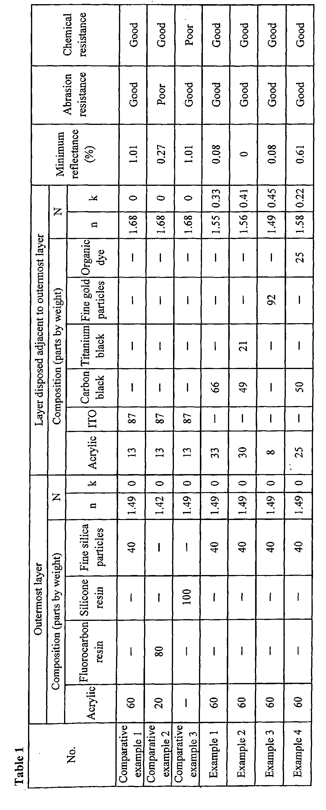
- the layer 3 was formed using a coating solution including a multifunctional acrylic resin and fine particles. Table 1 shows the composition of the coating solutions.
- a coating film serving as the outermost layer 4 i.e., low refractive index layer
- Table 1 also shows the composition of coating solutions used for the outermost layer 4.
- the layer 3 included a multifunctional acrylic resin and the following fine particles.
- carbon black particles were mixed with the acrylic resin.
- carbon black and titanium black particles were mixed with the acrylic resin.
- metal particles gold particles, average particle diameter 7 nm
- ITO particles average particle diameter 60 nm
- the outermost layer 4 included the multifunctional acrylic resin (60 parts by weight) and fine silica particles (40 parts by weight).
- the outermost layer 4 included the multifunctional acrylic resin (20 parts by weight) and a fluorocarbon resin (80 parts by weight).
- each resultant PET film was irradiated with ultraviolet rays to cure the acrylic resin.
- an antireflective film was produced.
- the antireflective film included a hard coat layer having a thickness of about 5 ⁇ m, the layer disposed adjacent to the outermost layer having a thickness of about 80 nm, and the outermost layer having a thickness of about 95 nm.
- Example 4 a layer 3 disposed adjacent to the outermost layer included the multifunctional acrylic resin (25 parts by weight), carbon black particles (50 parts by weight), and an organic dye (KAYASET Blue A-D from Nippon Kayaku Co., Ltd., 25 parts by weight).
- Other compositions were the same as those in Examples 1 to 3.
- the chemical resistance of the antireflective films was evaluated as follows: Each antireflective film was immersed in an aqueous solution of NaOH (3 weight percent) for 30 minutes. Furthermore, each antireflective film was immersed in an aqueous solution of HCl (3 weight percent) for 30 minutes. Subsequently, the chemical resistance was checked by visual inspection. Table 1 shows the result. In Table 1, the word good represents that the color of the reflected light did not change and the word poor represents that the color of the reflected light changed.
- the abrasion resistance of the antireflective films was evaluated as follows: Each antireflective film was rubbed with a commercially available plastic eraser back and forth for 100 times. The change in the appearance was checked by visual observation. Table 1 shows the result. In Table 1, the word good represents that the appearance did not change and the word poor represents that appearance changed.
- An antireflective film was produced as in Comparative examples 1 and 2 except that the outermost layer was composed of a silicone resin (that did not contain fine particles). The measurement and evaluations were performed in the same way. Table 1 shows the results.
- the antireflective film in Comparative example 1 was a normal transparent antireflective film formed by coating and had a high minimum reflectance.
- Comparative example 2 in order to decrease the minimum reflectance, a low refractive index layer including a fluorocarbon resin was used as the outermost layer. Although this antireflective film in Comparative example 2 had a low minimum reflectance, the abrasion resistance of the antireflective film was poor.
- Comparative example 3 the silicone resin was used as the outermost layer. According to the antireflective film in Comparative example 3, the minimum reflectance was not decreased that much, and in addition, the chemical resistance (alkali resistance) was poor.
- Example 1 carbon black particles were mixed in the layer disposed adjacent to the outermost layer.
- the antireflective film in Example 1 had a very low minimum reflectance and satisfied all performances.
- Example 2 carbon black and titanium black particles were mixed in the layer disposed adjacent to the outermost layer.
- the minimum reflectance of the antireflective film in Example 2 can be reduced to as low as zero.
- Example 3 fine gold particles (average particle diameter 7 nm) were mixed in the layer disposed adjacent to the outermost layer.
- the antireflective film in Example 3 had a very low minimum reflectance and satisfied all performances.
- Example 4 the organic dye and carbon black particles were mixed in the layer disposed adjacent to the outermost layer.
- the antireflective film in Example 4 had a very low minimum reflectance and satisfied all performances.
- the antireflective films in the above Examples and Comparative examples showed the good antistatic performance.
- the selection of the material that provides an excellent antireflective performance and can be used as the low refractive index layer can be increased. Furthermore, an antireflective film having excellent antireflective performance and abrasion resistance can be provided at a low cost using an acrylic resin, which is inexpensive and has excellent chemical resistance, adhesiveness, and weather resistance, as the outermost layer.
- FIG. 2 is a cross-sectional view showing an example of an antireflective film according to the second embodiment.
- a hard coat layer 12, a transparent conductive layer 13, a light-absorbing layer 14, and a low refractive index layer 15, in that order, are laminated on a transparent base film 11 by coating to form an antireflective film 10.
- the transparent base film 11 is composed of, for example, polyesters, polyethylene terephthalate (PET), polybutylene terephthalate, polymethylmethacrylate (PMMA), acrylics, polycarbonate (PC), polystyrene, triacetates, polyvinyl alcohol, polyvinyl chloride, polyvinylidene chloride, polyethylene, ethylene-vinyl acetate copolymer, polyurethanes, and cellophane.
- PET polyethylene terephthalate
- PMMA polymethylmethacrylate
- acrylics polycarbonate
- PC polystyrene
- triacetates polyvinyl alcohol, polyvinyl chloride, polyvinylidene chloride, polyethylene, ethylene-vinyl acetate copolymer, polyurethanes, and cellophane.
- Preferable examples include a transparent film composed of PET, PC, or PMMA.
- the thickness of the transparent base film 11 is appropriately determined according to required characteristics (for example, the strength and the thin film performance) depending on the application of the resultant antireflective film.
- the thickness of the transparent base film 11 is generally in the range of 1 ⁇ m to 10 mm.
- the hard coat layer 12 disposed on the transparent base film 11 can be formed by coating a normal hard coat agent composed of, for example, an acrylic resin or a silicone resin. According to need, about 0.05 to about 5 weight percent of a known ultraviolet absorber may be mixed in the hard coat layer 12 to provide an ultraviolet-cutting property.
- the hard coat layer 12 preferably has a film thickness of about 2 to about 20 ⁇ m.
- the transparent conductive layer 13 disposed on the hard coat layer 12 is preferably formed as follows: At least one kind of conductive fine particles selected from the group consisting of antimony-doped tin oxide (ATO), ZnO, Sb 2 O 5 , SnO 2 , indium tin oxide (ITO), and In 2 O 3 particles are mixed with a binder resin such as an acrylic resin to prepare a coating solution. The coating solution is coated on the hard coat layer 12 formed on the transparent base film 11. The resultant coated film is cured with heat or light, preferably with light.
- ATO antimony-doped tin oxide
- ZnO ZnO
- Sb 2 O 5 SnO 2
- ITO indium tin oxide
- ITO indium tin oxide
- In 2 O 3 particles In 2 O 3 particles
- the mixing ratio of the conductive fine particles to the binder resin is appropriately determined according to, for example, the refractive index of the transparent conductive layer 13 to be formed.
- the transparent conductive layer 13 preferably has a refractive index n of 1.58 to 1.75 at light having a wavelength of 550 nm by adequately controlling the mixing ratio of the conductive fine particles to the binder resin.
- the film thickness of the transparent conductive layer 13 is preferably at least 0.25 ⁇ , more preferably, 0.3 ⁇ to 0.6 ⁇ , most preferably, 0.3 ⁇ to 0.55 ⁇ of the light having a wavelength of 550 nm.
- the film thickness of the transparent conductive layer 13 is smaller than the above range, a sufficient conductive property cannot be provided. Consequently, the resultant antireflective film has a high surface resistivity.
- an excessively large thickness of the transparent conductive layer 13 significantly deteriorates the optical performance (i.e., antireflective performance).
- the conductive fine particles used in the transparent conductive layer 13 preferably have an average particle diameter of 5 to 100 nm.
- the light-absorbing layer 14 disposed on the transparent conductive layer 13 is preferably formed as follows: At least one kind of light-absorbing fine particles selected from the group consisting of metal oxide particles, metal nitride particles, and carbon particles are mixed with a binder resin such as an acrylic resin to prepare a coating solution. The coating solution is coated on the transparent conductive layer 13. The resultant coated film is cured with heat or light, preferably with light.
- the mixing ratio of the light-absorbing fine particles to the binder resin in this coating solution is appropriately determined according to, for example, the attenuation coefficient of the light-absorbing layer 14 to be formed.
- the attenuation coefficient k of the light-absorbing layer 14 is 0.25 or less, a sufficient antireflective performance cannot be provided. An excessively large attenuation coefficient k also deteriorates the antireflective performance.
- the film thickness of the light-absorbing layer 14 is preferably up to 0.25 ⁇ , more preferably, 0.12 ⁇ to 0.22 ⁇ of the light having a wavelength of 550 nm.
- the transmittance is decreased.
- an excessively small thickness of the light-absorbing layer 14 cannot provide a sufficient antireflective performance.
- Examples of the fine metal oxide particle in the light-absorbing layer 14 include titanium oxide particles.
- Examples of the fine metal nitride particle in the light-absorbing layer 14 include titanium nitride particles.
- titanium black which is a mixture of both compounds, is preferably used.
- the light-absorbing fine particles preferably have an average particle diameter of 5 to 100 nm.
- the low refractive index layer 15 disposed on the light-absorbing layer 14 preferably has an attenuation coefficient k of about zero at light having a wavelength of 550 nm.
- the low refractive index layer 15 preferably has a refractive index n of 1.38 to 1.55.
- the refractive index n of the low refractive index layer 15 is less than 1.38, the strength of the film is significantly decreased.
- the refractive index n of the low refractive index layer 15 exceeds 1.55, the antireflective performance is deteriorated.
- the low refractive index layer 15 is preferably composed of a silica-containing acrylic resin, which provides an excellent abrasion resistance.
- the low refractive index layer 15 is preferably formed as follows: A coating solution containing fine silica particles and an acrylic binder resin is coated on the light-absorbing layer 14. The resultant coated film is cured with heat or light, preferably with light.
- the mixing ratio of the fine silica particles to the binder resin in the coating solution is appropriately determined according to, for example, the refractive index of the low refractive index layer 15 to be formed.
- the low refractive index layer 15 that satisfies the above refractive index is preferably formed.
- the film thickness of the low refractive index layer 15 is preferably 0.10 ⁇ to 0.20 ⁇ of the light having a wavelength of 550 nm.
- the film thickness of the low refractive index layer 15 is smaller than the above range, the antireflective performance is deteriorated.
- An excessively large thickness of the low refractive index layer 15 also deteriorates the antireflective performance.
- the fine silica particles used in the low refractive index layer 15 preferably have an average particle diameter of 5 to 20 nm.
- the antireflective film according to the second embodiment has a luminous reflectance of 0.5% or less to provide an excellent antireflective performance.
- the antireflective film has a low surface resistivity of 1 ⁇ 10 8 ⁇ /square or less, furthermore, 9 ⁇ 10 7 ⁇ /square or less to provide an excellent antistatic performance. Therefore, in particular, the antireflective film according to the second embodiment can be preferably used as an antireflective film for a CRT screen.
- the application of this antireflective film is not limited to the antireflective film for a CRT screen.
- the antireflective film is useful in, for example, a plasma television and a liquid crystal television.
- Fine ITO particles had an average particle diameter of 50 nm.
- Fine carbon particles had an average secondary particle diameter of 100 nm.
- Fine titanium black particles had an average particle diameter of 60 nm.
- Fine silica particles had an average particle diameter of 12 nm.
- the wavelength ⁇ was 550 nm.
- a photo-curable acrylic hard coat agent (Z7501 from JSR Corporation) was applied on an easily adherable layer of a PET film (A4100 from Toyobo Co., Ltd.).
- the resultant PET film was irradiated with a high-pressure mercury lamp to cure the hard coat agent under the conditions of 200 ppm or less of the oxygen concentration and 500 mJ/cm 2 of the integrated light intensity.
- a hard coat layer having a thickness of 8 ⁇ m was formed.
- the resultant PET film was irradiated with the high-pressure mercury lamp to cure the coating solution under the conditions of 200 ppm or less of the oxygen concentration and 500 mJ/cm 2 of the integrated light intensity.
- the resultant PET film was irradiated with the high-pressure mercury lamp to cure the coating solution under the conditions of 200 ppm or less of the oxygen concentration and 500 mJ/cm 2 of the integrated light intensity.
- the resultant PET film was irradiated with the high-pressure mercury lamp to cure the coating solution under the conditions of 200 ppm or less of the oxygen concentration and 500 mJ/cm 2 of the integrated light intensity.
- the surface resistivity was measured with a resistivity meter (Hiresta UP from Mitsubishi Chemical Corporation) and was evaluated according to the following criterion.
- the surface resistivity is 8.0 ⁇ 10 7 ⁇ /square or less.
- the electrical conductivity is excellent.
- the surface resistivity exceeds 8.0 ⁇ 10 7 ⁇ /square and is up to 2 ⁇ 10 8 ⁇ /square.
- the electrical conductivity is good.
- the surface resistivity exceeds 2 ⁇ 10 8 ⁇ /square.
- the electrical conductivity is low.
- the outermost surface of the antireflective film was rubbed with an eraser with a constant load. When no scratch was generated after the antireflective film was rubbed more than 50 times, the antireflective film was evaluated as good. When a scratch was generated after the antireflective film was rubbed 50 times or less, the antireflective film was evaluated as poor.
- a black tape was applied on the back-side of the antireflective film.
- the minimum reflectance was measured with a spectrophotometer (from Hitachi, Ltd.) and was evaluated according to the following criterion.
- the minimum reflectance is 0.3% or less.
- the antireflective performance is good.
- the minimum reflectance is 0.4% or more.
- the antireflective performance is poor.
- the luminous reflectance is 0.5% or less.
- the antireflective performance is good.
- the luminous reflectance is 0.6% or more.
- the antireflective performance is poor.
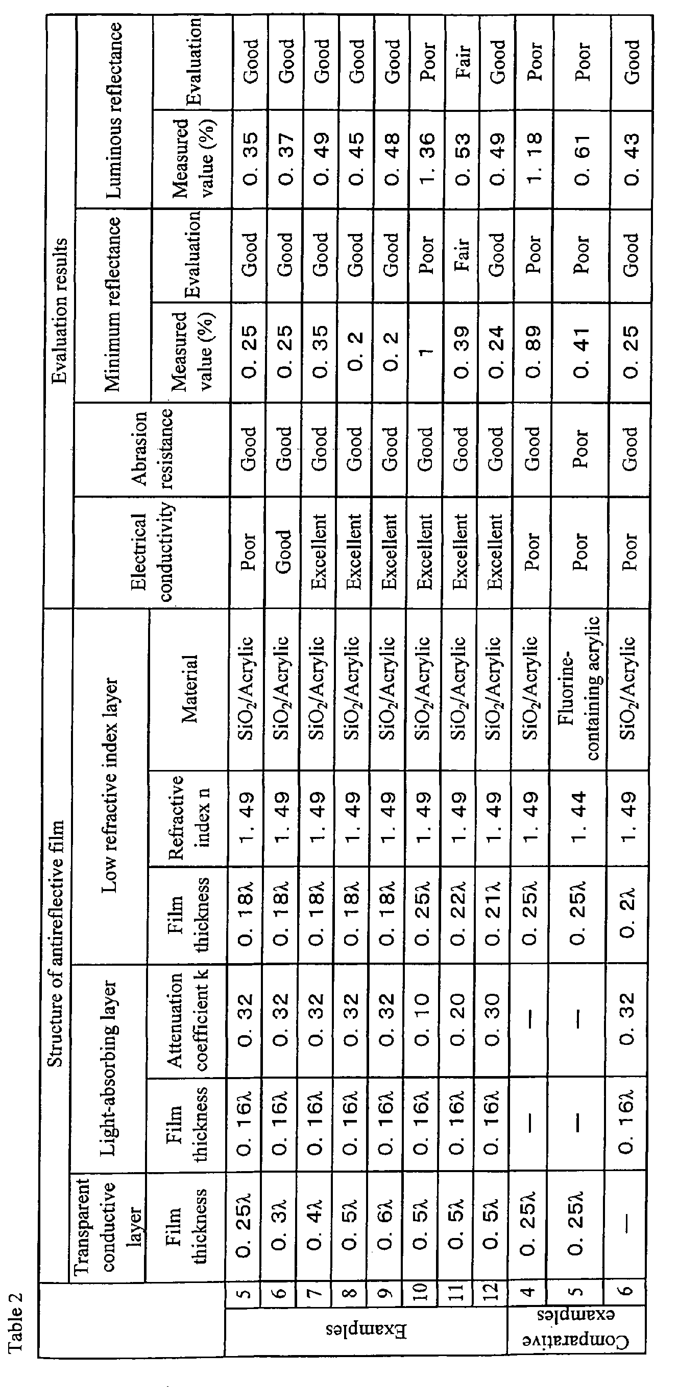
- Antireflective films were produced as in Example 5 except that the film thickness of the transparent conductive layer was changed as shown in Table 2.
- the electrical conductivity, the abrasion resistance, the minimum reflectance, and the luminous reflectance were evaluated as in Example 5. Table 2 shows the results.
- the resultant PET film was irradiated with a high-pressure mercury lamp to cure the coating solution under the conditions of 200 ppm or less of the oxygen concentration and 500 mJ/cm 2 of the integrated light intensity.
- the resultant PET film was irradiated with the high-pressure mercury lamp to cure the coating solution under the conditions of 200 ppm or less of the oxygen concentration and 500 mJ/cm 2 of the integrated light intensity.
- the resultant PET film was irradiated with the high-pressure mercury lamp to cure the coating solution under the conditions of 200 ppm or less of the oxygen concentration and 500 mJ/cm 2 of the integrated light intensity.
- the resultant PET film was irradiated with a high-pressure mercury lamp to cure the coating solution under the conditions of 200 ppm or less of the oxygen concentration and 500 mJ/cm 2 of the integrated light intensity.
- the resultant PET film was irradiated with the high-pressure mercury lamp to cure the coating solution under the conditions of 200 ppm or less of the oxygen concentration and 500 mJ/cm 2 of the integrated light intensity.
- the resultant PET film was irradiated with a high-pressure mercury lamp to cure the coating solution under the conditions of 200 ppm or less of the oxygen concentration and 500 mJ/cm 2 of the integrated light intensity.
- the resultant PET film was irradiated with the high-pressure mercury lamp to cure the coating solution under the conditions of 200 ppm or less of the oxygen concentration and 500 mJ/cm 2 of the integrated light intensity.
- Example 5 An antireflective film was produced as in Example 5 except that the light-absorbing layer was not formed and the low refractive index layer was formed so as to have a thickness of about 0.25 ⁇ .
- the electrical conductivity, the abrasion resistance, the minimum reflectance, and the luminous reflectance were evaluated as in Example 5. Table 2 shows the results.
- An antireflective film was produced as in Example 5 except that the light-absorbing layer was not formed and the low refractive index layer was formed as follows.
- a fluorine-containing acrylic resin was coated on the transparent conductive layer.
- the resultant PET film was irradiated with a high-pressure mercury lamp to cure the acrylic resin under the conditions of 200 ppm or less of the oxygen concentration and 500 mJ/cm 2 of the integrated light intensity.
- the electrical conductivity, the abrasion resistance, the minimum reflectance, and the luminous reflectance were evaluated as in Example 5. Table 2 shows the results.
- Example 5 An antireflective film was produced as in Example 5 except that the transparent conductive layer was not formed and the low refractive index layer was formed so as to have a thickness of about 0.2 ⁇ .
- the electrical conductivity, the abrasion resistance, the minimum reflectance, and the luminous reflectance were evaluated as in Example 5. Table 2 shows the results.
- the antireflective film in Comparative example 6 which does not include the transparent conductive layer, had a low minimum reflectance and a low luminous reflectance, the antireflective film had a poor electrical conductivity.
- the antireflective films in Examples 5 to 9 included the transparent conductive layer and the light-absorbing layer.
- the thickness of the transparent conductive layer was gradually increased to evaluate the change in the electrical conductivity. Since the attenuation coefficient k was as large as 0.32, all antireflective films showed a good antireflective performance.
- the transparent conductive layer had a thickness of at least 0.3 ⁇ , the target surface resistivity of 1 ⁇ 10 8 ⁇ /square or less can be achieved.
- the transparent conductive layer had a sufficient film thickness (0.5 ⁇ ) and the ratio of the fine carbon particles and the fine titanium black particles in the light-absorbing layer to the acrylic binder was changed to evaluate the change in the antireflective performance.
- the attenuation coefficient k of the light-absorbing layer was at least 0.25, a satisfactory antireflective performance can be provided in terms of the minimum reflectance and the luminous reflectance.
- an antireflective film having a significantly excellent antireflective performance and antistatic performance can be provided by coating at a low cost.
Landscapes
- Physics & Mathematics (AREA)
- General Physics & Mathematics (AREA)
- Optics & Photonics (AREA)
- Surface Treatment Of Optical Elements (AREA)
- Laminated Bodies (AREA)
Abstract
Description
The electrical conductivity is low.
Claims (20)
- An antireflective film comprising:wherein a layer disposed adjacent to the outermost layer that is disposed farthest from the base film has a light-absorbing property.a base film; anda plurality of thin films coated on the base film,
- The antireflective film according to claim 1, wherein the attenuation coefficient k at a wavelength of 550 nm of the outermost layer is represented by k<0.01.
- The antireflective film according to claim 1, wherein the attenuation coefficient k at a wavelength of 550 nm of the layer disposed adjacent to the outermost layer is represented by 0.1<k<5.
- The antireflective film according to claim 3, wherein the layer disposed adjacent to the outermost layer comprises an organic resin in which fine particles are dispersed.
- The antireflective film according to claim 4, wherein the fine particles are at least one kind of particles selected from the group consisting of carbon black, fullerene, and titanium black particles.
- The antireflective film according to claim 1, wherein the layer disposed adjacent to the outermost layer comprises fine metal particles to provide the light-absorbing property.
- The antireflective film according to claim 6, wherein the layer disposed adjacent to the outermost layer comprises an organic resin in which the fine metal particles are dispersed.
- The antireflective film according to claim 6, wherein the fine metal particles are fine noble metal particles.
- The antireflective film according to claim 8, wherein the noble metal is at least one of gold and silver.
- The antireflective film according to claim 1, wherein the layer disposed adjacent to the outermost layer comprises an organic dye to provide the light-absorbing property.
- The antireflective film according to claim 10, wherein the layer disposed adjacent to the outermost layer comprises an organic resin in which conductive fine particles are dispersed.
- The antireflective film according to claim 11, wherein the conductive fine particles are at least one kind of particles selected from the group consisting of ZnO, indium tin oxide, antimony-doped tin oxide, SbO2, and conductive carbon black particles.
- The antireflective film according to claim 1, wherein the layer disposed adjacent to the outermost layer has a real part of the refractive index of 1.45 to 1.85.
- The antireflective film according to claim 1, wherein the outermost layer has a refractive index of 1.40 to 1.52.
- An antireflective film comprising:wherein the hard coat layer, the transparent conductive layer, the light-absorbing layer, and the low refractive index layer are formed by coating.a transparent base film;a hard coat layer laminated on the transparent base film;a transparent conductive layer laminated on the hard coat layer;a light-absorbing layer laminated on the transparent conductive layer; anda low refractive index layer laminated on the light-absorbing layer,
- The antireflective film according to claim 15, wherein the hard coat layer has a film thickness of 2 to 20 µm.
- The antireflective film according to claim 15, wherein the transparent conductive layer comprises a cured acrylic binder resin including at least one kind of fine particles selected from the group consisting of antimony-doped tin oxide, ZnO, Sb2O5, SnO2, indium tin oxide, and In2O3 particles; and
the transparent conductive layer has a thickness of 0.3λ to 0.6λ of light having a wavelength of 550 nm and a refractive index of 1.58 to 1.75 to the light having a wavelength of 550 nm. - The antireflective film according to claim 15, wherein the light-absorbing layer comprises a cured acrylic binder resin including at least one kind of fine particles selected from the group consisting of metal oxide particles, metal nitride particles, and carbon particles;
the attenuation coefficient of the light-absorbing layer at light having a wavelength of 550 nm is more than 0.25, and the light-absorbing layer has a thickness of 0.25λ or less of the light having a wavelength of 550 nm. - The antireflective film according to claim 15, wherein the attenuation coefficient of the low refractive index layer at light having a wavelength of 550 nm is about zero, and the low refractive index layer has a refractive index of 1.38 to 1.55 to the light having a wavelength of 550 nm.
- The antireflective film according to claim 15, wherein the surface resistivity is 1.0×10⁸ Ω/square or less and the luminous reflectance is 0.5% or less.
Applications Claiming Priority (9)
| Application Number | Priority Date | Filing Date | Title |
|---|---|---|---|
| JP2002290168 | 2002-10-02 | ||
| JP2002290170 | 2002-10-02 | ||
| JP2002290169 | 2002-10-02 | ||
| JP2002290170 | 2002-10-02 | ||
| JP2002290168 | 2002-10-02 | ||
| JP2002290169 | 2002-10-02 | ||
| JP2002318349 | 2002-10-31 | ||
| JP2002318349 | 2002-10-31 | ||
| PCT/JP2003/011969 WO2004031813A1 (en) | 2002-10-02 | 2003-09-19 | Anti-reflection film |
Publications (2)
| Publication Number | Publication Date |
|---|---|
| EP1548469A1 true EP1548469A1 (en) | 2005-06-29 |
| EP1548469A4 EP1548469A4 (en) | 2010-12-15 |
Family
ID=32074566
Family Applications (1)
| Application Number | Title | Priority Date | Filing Date |
|---|---|---|---|
| EP03799113A Withdrawn EP1548469A4 (en) | 2002-10-02 | 2003-09-19 | Anti-reflection film |
Country Status (5)
| Country | Link |
|---|---|
| US (1) | US20050233131A1 (en) |
| EP (1) | EP1548469A4 (en) |
| JP (1) | JP4400458B2 (en) |
| AU (1) | AU2003264510A1 (en) |
| WO (1) | WO2004031813A1 (en) |
Cited By (1)
| Publication number | Priority date | Publication date | Assignee | Title |
|---|---|---|---|---|
| US10310143B2 (en) | 2013-12-03 | 2019-06-04 | Fujifilm Corporation | Anti-reflection optical member |
Families Citing this family (26)
| Publication number | Priority date | Publication date | Assignee | Title |
|---|---|---|---|---|
| WO2004031814A1 (en) * | 2002-10-02 | 2004-04-15 | Bridgestone Corporation | Optical base and antireflection film |
| JP2005120232A (en) * | 2003-10-16 | 2005-05-12 | Mitsubishi Chem Mkv Co | UV-absorbing coating composition and UV-absorbing film |
| JP4710269B2 (en) * | 2004-07-21 | 2011-06-29 | 凸版印刷株式会社 | Antireflection laminated film and display medium using the same |
| WO2006062251A1 (en) * | 2004-12-10 | 2006-06-15 | Bridgestone Corporation | Reflection preventing film having conductor layer for field emission type display, manufacturing method thereof, and field emission type display |
| KR100637201B1 (en) * | 2004-12-20 | 2006-10-23 | 삼성에스디아이 주식회사 | Organic electroluminescent device and manufacturing method thereof |
| JP5008273B2 (en) * | 2005-05-06 | 2012-08-22 | アンデス電気株式会社 | Electrochemical display element |
| JP2007066711A (en) * | 2005-08-31 | 2007-03-15 | Tdk Corp | Transparent conductor and transparent conductive film using it |
| KR100992921B1 (en) * | 2007-08-29 | 2010-11-09 | 삼성코닝정밀소재 주식회사 | Display device filter and display device having same |
| US20090058250A1 (en) * | 2007-08-29 | 2009-03-05 | Samsung Corning Precision Glass Co., Ltd. | Filter for display apparatus |
| US7744782B2 (en) * | 2007-08-30 | 2010-06-29 | Tdk Corporation | Transparent conductor |
| JP2010072347A (en) * | 2008-09-18 | 2010-04-02 | Kamakura Koki Kk | Optical interference thin film |
| JP5455387B2 (en) * | 2009-01-30 | 2014-03-26 | キヤノン株式会社 | Film and optical lens formed on outer peripheral surface of lens |
| US8770749B2 (en) | 2010-04-15 | 2014-07-08 | Oakley, Inc. | Eyewear with chroma enhancement |
| EP2649478B1 (en) * | 2010-12-10 | 2020-05-27 | 3M Innovative Properties Company | Glare reducing glazing articles |
| BR112014009556A2 (en) | 2011-10-20 | 2017-06-13 | Oakley, Inc | glasses, laminates and their methods of making them |
| WO2013169987A1 (en) | 2012-05-10 | 2013-11-14 | Oakley, Inc. | Eyewear with laminated functional layers |
| CN104871060B (en) * | 2012-12-17 | 2017-10-31 | 旭硝子株式会社 | Optical element, optical system and imaging device |
| KR101510563B1 (en) | 2013-12-10 | 2015-04-08 | 영남대학교 산학협력단 | Antireflection film |
| US9575335B1 (en) | 2014-01-10 | 2017-02-21 | Oakley, Inc. | Eyewear with chroma enhancement for specific activities |
| EP3218763A4 (en) | 2014-11-13 | 2018-06-13 | Oakley, Inc. | Variable light attenuation eyewear with color enhancement |
| JP2016102873A (en) * | 2014-11-27 | 2016-06-02 | 富士フイルム株式会社 | Antireflective optical member |
| JP6514657B2 (en) | 2015-03-11 | 2019-05-15 | 富士フイルム株式会社 | Antireflection optical member |
| JPWO2017068789A1 (en) * | 2015-10-21 | 2018-07-26 | 富士フイルム株式会社 | Antireflection film and functional glass |
| JPWO2017159621A1 (en) * | 2016-03-18 | 2018-08-23 | 富士フイルム株式会社 | Antireflection film and functional glass |
| US12124116B2 (en) | 2017-10-20 | 2024-10-22 | Luxottica S.R.L. | Eyewear with variable transmission lens |
| US11112622B2 (en) | 2018-02-01 | 2021-09-07 | Luxottica S.R.L. | Eyewear and lenses with multiple molded lens components |
Family Cites Families (19)
| Publication number | Priority date | Publication date | Assignee | Title |
|---|---|---|---|---|
| AT210638B (en) * | 1958-11-18 | 1960-08-10 | Contina Ag | Arrangement to prevent unwanted reflections at the interfaces of optical elements |
| GB1173303A (en) * | 1968-08-20 | 1969-12-10 | Canon Camera Company Ltd | Coated Optical Glass |
| JP2702821B2 (en) * | 1991-05-13 | 1998-01-26 | 三菱電機株式会社 | CRT with low reflection film |
| JP3779337B2 (en) * | 1992-11-06 | 2006-05-24 | 株式会社東芝 | Antireflection film and display device |
| JPH07134956A (en) * | 1993-11-11 | 1995-05-23 | Hitachi Ltd | Cathode ray tube and manufacturing method thereof |
| JP4034365B2 (en) * | 1995-03-09 | 2008-01-16 | 大日本印刷株式会社 | Ultrafine particle-containing antireflection film, polarizing plate and liquid crystal display device |
| JP3520627B2 (en) * | 1995-09-14 | 2004-04-19 | ソニー株式会社 | Anti-reflection member, method of manufacturing the same, and cathode ray tube |
| US5728456A (en) * | 1996-02-01 | 1998-03-17 | Optical Coating Laboratory, Inc. | Methods and apparatus for providing an absorbing, broad band, low brightness, antireflection coating |
| US5925438A (en) * | 1996-06-17 | 1999-07-20 | Dai Nippon Printing Co., Ltd. | Antireflection film |
| JPH1021858A (en) * | 1996-07-02 | 1998-01-23 | Hitachi Ltd | High contrast cathode ray tube and method of manufacturing the same |
| US6319594B1 (en) * | 1998-03-17 | 2001-11-20 | Dai Nippon Printing Co., Ltd. | Low reflective antistatic hardcoat film |
| JP2000137111A (en) * | 1998-11-02 | 2000-05-16 | Sony Corp | Display device filter and display device |
| JP2000193801A (en) * | 1998-12-25 | 2000-07-14 | Asahi Glass Co Ltd | Light absorbing anti-reflective coating |
| US6480250B1 (en) * | 1999-06-02 | 2002-11-12 | Fuji Photo Film Co., Ltd. | Low-reflection transparent conductive multi layer film having at least one transparent protective layer having anti-smudge properties |
| JP2000356703A (en) * | 1999-06-15 | 2000-12-26 | Nippon Electric Glass Co Ltd | Conductive reflection preventing film |
| JP2001242302A (en) * | 1999-12-22 | 2001-09-07 | Sony Corp | Light-absorbing antireflection film, display device, and method of manufacturing the same |
| US6605341B2 (en) * | 2000-05-19 | 2003-08-12 | Tdk Corporation | Functional film having specific surface dispersion ratio |
| JP2002062401A (en) * | 2000-08-14 | 2002-02-28 | Fuji Photo Film Co Ltd | Anti-reflective transparent conductive laminated film |
| JP2002098803A (en) * | 2000-09-22 | 2002-04-05 | Fuji Photo Film Co Ltd | Transparent conductive / anti-reflection film and display device using the same |
-
2003
- 2003-09-19 WO PCT/JP2003/011969 patent/WO2004031813A1/en not_active Ceased
- 2003-09-19 JP JP2004541229A patent/JP4400458B2/en not_active Expired - Fee Related
- 2003-09-19 EP EP03799113A patent/EP1548469A4/en not_active Withdrawn
- 2003-09-19 AU AU2003264510A patent/AU2003264510A1/en not_active Abandoned
-
2005
- 2005-03-29 US US11/091,505 patent/US20050233131A1/en not_active Abandoned
Cited By (1)
| Publication number | Priority date | Publication date | Assignee | Title |
|---|---|---|---|---|
| US10310143B2 (en) | 2013-12-03 | 2019-06-04 | Fujifilm Corporation | Anti-reflection optical member |
Also Published As
| Publication number | Publication date |
|---|---|
| JPWO2004031813A1 (en) | 2006-02-02 |
| EP1548469A4 (en) | 2010-12-15 |
| AU2003264510A1 (en) | 2004-04-23 |
| JP4400458B2 (en) | 2010-01-20 |
| WO2004031813A1 (en) | 2004-04-15 |
| US20050233131A1 (en) | 2005-10-20 |
Similar Documents
| Publication | Publication Date | Title |
|---|---|---|
| US20050233131A1 (en) | Antireflective film | |
| KR101074948B1 (en) | Antireflection film, electromagnetic wave shielding light transmitting window material, gas discharge type light emitting panel, flat display panel, show window material and solar cell module | |
| US20080305282A1 (en) | Antireflection film and display front plate using the same | |
| JP6427968B2 (en) | Antireflection film and display | |
| JP4906283B2 (en) | Infrared absorption film | |
| JP2005004163A (en) | Optical functional film, polarizing plate and image display device | |
| JP2007293324A (en) | Optical laminate | |
| JP2005313620A (en) | Thin film laminate | |
| JP4285059B2 (en) | Transparent conductive material and touch panel | |
| CN1955762B (en) | Optical thin film and its manufacturing method | |
| JP2006126808A (en) | Optical laminate | |
| US20010053438A1 (en) | Antireflection film | |
| JP4756336B2 (en) | Optical laminate | |
| JP4895160B2 (en) | Optical laminate | |
| JP2007322877A (en) | Optical laminate | |
| JP2001021701A (en) | Transparent film with antistatic / antireflective coating | |
| JP2004012592A (en) | Near-infrared absorbing and anti-reflective composite functional film | |
| KR100709866B1 (en) | Low reflectance luminance improving optical film for display device and display device using same | |
| KR101192387B1 (en) | Optical laminate | |
| JP2001264507A (en) | Anti-reflective material, manufacturing method and application | |
| JP2005181544A (en) | Antireflection film | |
| JP2009015289A (en) | Antireflection film and display front plate using the same | |
| JP4883387B2 (en) | Optical laminate | |
| JP2004258209A (en) | Antireflection film | |
| JP2008185956A (en) | Antireflection film and transparent base material with the antireflection film |
Legal Events
| Date | Code | Title | Description |
|---|---|---|---|
| PUAI | Public reference made under article 153(3) epc to a published international application that has entered the european phase |
Free format text: ORIGINAL CODE: 0009012 |
|
| 17P | Request for examination filed |
Effective date: 20050408 |
|
| AK | Designated contracting states |
Kind code of ref document: A1 Designated state(s): AT BE BG CH CY CZ DE DK EE ES FI FR GB GR HU IE IT LI LU MC NL PT RO SE SI SK TR |
|
| AX | Request for extension of the european patent |
Extension state: AL LT LV MK |
|
| DAX | Request for extension of the european patent (deleted) | ||
| RBV | Designated contracting states (corrected) |
Designated state(s): DE FR GB NL |
|
| A4 | Supplementary search report drawn up and despatched |
Effective date: 20101102 |
|
| RIC1 | Information provided on ipc code assigned before grant |
Ipc: G02B 27/00 20060101ALI20101026BHEP Ipc: H01J 29/89 20060101ALI20101026BHEP Ipc: G09F 9/00 20060101ALI20101026BHEP Ipc: G02B 1/10 20060101AFI20040420BHEP |
|
| RA4 | Supplementary search report drawn up and despatched (corrected) |
Effective date: 20101111 |
|
| 17Q | First examination report despatched |
Effective date: 20110309 |
|
| STAA | Information on the status of an ep patent application or granted ep patent |
Free format text: STATUS: THE APPLICATION IS DEEMED TO BE WITHDRAWN |
|
| 18D | Application deemed to be withdrawn |
Effective date: 20130716 |