EP1548416B1 - Méthode et dispositif pour contrôler la température le long d'une ligne de mesure - Google Patents
Méthode et dispositif pour contrôler la température le long d'une ligne de mesure Download PDFInfo
- Publication number
- EP1548416B1 EP1548416B1 EP04030272A EP04030272A EP1548416B1 EP 1548416 B1 EP1548416 B1 EP 1548416B1 EP 04030272 A EP04030272 A EP 04030272A EP 04030272 A EP04030272 A EP 04030272A EP 1548416 B1 EP1548416 B1 EP 1548416B1
- Authority
- EP
- European Patent Office
- Prior art keywords
- signal
- frequency
- measuring line
- evaluation circuit
- temperature change
- Prior art date
- Legal status (The legal status is an assumption and is not a legal conclusion. Google has not performed a legal analysis and makes no representation as to the accuracy of the status listed.)
- Expired - Lifetime
Links
- 238000000034 method Methods 0.000 title claims description 14
- 230000004044 response Effects 0.000 claims description 25
- 238000011156 evaluation Methods 0.000 claims description 23
- 230000008859 change Effects 0.000 claims description 19
- 238000010438 heat treatment Methods 0.000 claims description 8
- 238000013021 overheating Methods 0.000 claims description 8
- 238000001914 filtration Methods 0.000 claims description 5
- 230000001939 inductive effect Effects 0.000 claims description 4
- 230000009466 transformation Effects 0.000 claims description 2
- 238000001514 detection method Methods 0.000 description 23
- 230000005540 biological transmission Effects 0.000 description 14
- 238000005259 measurement Methods 0.000 description 9
- 150000003839 salts Chemical class 0.000 description 6
- 230000005496 eutectics Effects 0.000 description 5
- 238000012423 maintenance Methods 0.000 description 5
- 230000003044 adaptive effect Effects 0.000 description 4
- 239000004020 conductor Substances 0.000 description 3
- 238000010586 diagram Methods 0.000 description 3
- 230000004807 localization Effects 0.000 description 3
- 238000012360 testing method Methods 0.000 description 3
- 230000007547 defect Effects 0.000 description 2
- 230000001419 dependent effect Effects 0.000 description 2
- 238000013461 design Methods 0.000 description 2
- 230000000694 effects Effects 0.000 description 2
- 239000000835 fiber Substances 0.000 description 2
- 239000012535 impurity Substances 0.000 description 2
- 238000000691 measurement method Methods 0.000 description 2
- 230000003287 optical effect Effects 0.000 description 2
- 238000012545 processing Methods 0.000 description 2
- 230000009467 reduction Effects 0.000 description 2
- 230000003595 spectral effect Effects 0.000 description 2
- 238000001228 spectrum Methods 0.000 description 2
- 238000013024 troubleshooting Methods 0.000 description 2
- 238000004378 air conditioning Methods 0.000 description 1
- 230000002238 attenuated effect Effects 0.000 description 1
- 230000008901 benefit Effects 0.000 description 1
- 238000006243 chemical reaction Methods 0.000 description 1
- 230000007423 decrease Effects 0.000 description 1
- 230000003111 delayed effect Effects 0.000 description 1
- 238000011161 development Methods 0.000 description 1
- 239000000446 fuel Substances 0.000 description 1
- 239000003365 glass fiber Substances 0.000 description 1
- 238000009413 insulation Methods 0.000 description 1
- 230000010354 integration Effects 0.000 description 1
- 239000000463 material Substances 0.000 description 1
- 239000000203 mixture Substances 0.000 description 1
- 238000012806 monitoring device Methods 0.000 description 1
- 239000002245 particle Substances 0.000 description 1
- 238000010079 rubber tapping Methods 0.000 description 1
- 238000005070 sampling Methods 0.000 description 1
- 239000000779 smoke Substances 0.000 description 1
- 238000002604 ultrasonography Methods 0.000 description 1
- 239000013585 weight reducing agent Substances 0.000 description 1
Images
Classifications
-
- G—PHYSICS
- G01—MEASURING; TESTING
- G01K—MEASURING TEMPERATURE; MEASURING QUANTITY OF HEAT; THERMALLY-SENSITIVE ELEMENTS NOT OTHERWISE PROVIDED FOR
- G01K3/00—Thermometers giving results other than momentary value of temperature
- G01K3/08—Thermometers giving results other than momentary value of temperature giving differences of values; giving differentiated values
- G01K3/14—Thermometers giving results other than momentary value of temperature giving differences of values; giving differentiated values in respect of space
Definitions
- the present invention relates to a detection device for detecting a location along a measurement line at which a temperature change takes place and a method for detecting a location along a measurement line at which a temperature change takes place.
- hot air supply pipes are routed from the engines to the cabin.
- the hot air supply pipes are provided with Wam wires for the detection of leaks.
- this sensor line is a coaxial cable with center conductor and shell with thermally-sensitive, eutectic salt as insulation.
- Such a double-core cable with center conductor and shell with thermally sensitive eutectic salt is also applicable only for a temperature threshold corresponding to the material properties of the eutectic salt. Changes in this temperature threshold are only very limited and then require a costly development effort, eg to develop a new corresponding salt. Accordingly, this known solution allows no adjustment of the temperature threshold without much effort.
- EP-A-1 239 432 relates to a method for detecting and reporting overheating and fire in an aircraft, the method being an optical method using a glass fiber.
- the temperatures are determined using the Rayleigh scattering principle in the fiber optic cable, using the temperature dependence of the refractive properties of the fiber optic cable. By means of the Fresnel effect, the location of the temperature increase can be determined.
- the light pulses used are generated by a laser, which is turned on and off accordingly.
- EP-A-0 940 789 relates to a method and a sensor for fire detection with the aid of ultrasonic signals and light signals or microwave signals.
- the ultrasound signals are emitted together with the light signals or microwave signals from a first transmitter group, and the Doppler signals reflected by a medium are received by a corresponding receiver group.
- smoke, particles or changes in a gas composition in the detection area can be detected.
- EP-A-0 692 705 relates to an arrangement and a method for optical evaluation of backscattered light signals for determining a distance-dependent measurement profile of a backscatter medium.
- the method can be used to determine a temperature profile of the backscatter medium.
- amplitude-modulated and timed in frequency tuned light is irradiated into the backscatter medium and evaluated the backscattered light using a reference signal and corresponding evaluation.
- a detection device which has a signal generator, an evaluation electronics and a measuring line.
- the signal generator feeds a transmission signal into the measuring line.
- An electronic evaluation unit receives a response signal of the measuring line to the transmission signal and determines the location of the temperature change on the basis of the response signal.
- the transmission signal is fed into the measuring line and, on the basis of the response signal of the measuring line to the transmission signal, the location of the temperature change is determined by the evaluation electronics.
- this allows a simple, fast and accurate determination of a location of the temperature change.
- a location of a leak can be limited to a maintenance flap of the aircraft, whereby a maintenance effort in the event of leakage is reduced.
- the FMCW (Frequency Modulated Continuous Wave) principle is used.
- This is a Frequency-modulated swept microwave signal from the frequency generator in the measuring line, which may be, for example, a single, two or multi-core cable, fed.
- the response of the measurement line to the input signal, ie, the reflected signal, is mixed or multiplied with the transmission signal, thereby generating a difference frequency containing the distance information.
- the frequency of the transmission signal is changed linearly with time. In this way one obtains the distance information to the defect (the leak or the place where the temperature change takes place) in the frequency domain. This can then be easily evaluated, for example via a fast Fourier transform.
- an alarm threshold and the response characteristic of the detection means can be easily adjusted in a wide range by appropriate selection of the cable type and by setting the transmitter.
- an adaptive equalization and processing in the image or frequency range a very high accuracy can be achieved, thereby reducing the maintenance effort for troubleshooting.
- substantially all components of the detection device according to an embodiment of the present invention can be realized in digital form, which leads to a simple and inexpensive detection device.
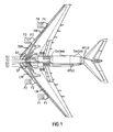
- Fig. 1 shows an embodiment of the arrangement of measuring lines of the detection device according to the present invention as they can be arranged for example in an aircraft of the type Airbus A380.
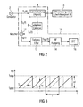
- Fig. 2 shows a simplified block diagram of an embodiment of the detection device according to the present invention.
- Fig. 3 shows a timing diagram showing a frequency characteristic of the transmitter signal and a frequency characteristic of the received signal in the detection device according to the present invention.
- FIGS. 1 to 3 An embodiment of the detection device for detecting a location along a measuring line on which a temperature change takes place is described on the basis of a temperature monitoring device for hot air supply pipes of an aircraft. It should be understood, however, that the present invention is not limited to use in an aircraft. Also, the present invention is not limited to the detection of a temperature rise but also applicable to the detection of a local temperature drop. Furthermore, the present invention is also applicable, for example, to fire alarm systems both inside and outside aircraft.
- Fig. 1 shows the course of test leads or warning wires along hot air supply pipes using the example of an aircraft of the Airbus 380 type Fig. 1
- the measuring lines have a large length, whereby, for example, a reduction in a diameter of the measuring lines or a reduction in the weight of the structure of the measuring line a significant weight reduction for the Plane can bring with it and thus a fuel saving.
- Fig. 1 it can be seen that the measuring wires are even arranged along the hot air tapping pipes in the engine area.
- the terms used for the test leads are arbitrary and show only how associated test leads can be routed.
- Fig. 2 shows a simplified block diagram of an embodiment of a detection device according to the present invention.
- the reference numeral 2 denotes a signal generator, which feeds the signal S s (t) into an evaluation electronics 18, which feeds the signal S s (t) into the measuring line 6.
- the signal S s (t) from the generator 2 via a hybrid circuit 4, which may be a hybrid circuit, fed into the measuring line 6.
- the response of the measuring line 6 to the injected signal S s (t) is fed from the measuring line 6 back into the evaluation electronics 18, namely in the hybrid circuit 4, where the response signal from the measuring line, that is, the transmitted signal S s (t ) is split off and fed via an adaptive equalizer 8 as a signal S r (t) in a mixer (multiplier) 10.
- the mixer or multiplier 10 multiplies the signal S s (t) by the signal S r (t) to obtain a signal S a (t), which after a low-pass filtering in a low-pass filter 12 as a signal S nf (t) to a LF output 14 is forwarded, from which it is forwarded, for example, to a fast Fourier transformer 16.
- NF stands for low frequency in this example.
- the frequency modulated continuous wave (FMCW) principle is advantageously used for lines as fire and overheat warning systems.
- FMCW frequency modulated continuous wave
- FIG. 10 is a timing chart illustrating a frequency characteristic of the sensor signal S s (t) and the reception signal, namely, the signal reflected from the measurement line 6 in response to the transmission signal S s (t).
- the frequency response of the transmission signal S s (t) is shown by a solid line and the frequency response of the received signal, ie the response signal of the measuring line 6, is shown by a dashed line.
- the signal generator 2 changes the frequency of the transmission signal S s (t) preferably in the microwave frequency range between the frequency f stop and f start .
- a frequency difference of f stop and f start is referred to as ⁇ f or frequency sweep.
- in Fig. 2 illustrated detection device when the signal generator 2, the in Fig. 3 illustrated transmission signal S s (t) via the transmitter 18 in the measuring line 6 feeds and the transmitter 18 analyzes the reflected signal from the measuring line 6 signal according to the FMCW method.
- a period T of the transmission signal S s (t) is considerably greater than a transit time ⁇ of the received signal
- multiplication (by means of the mixer 10) of the transmitted with the reflected signal results in a difference frequency f d containing the distance information.
- the frequency f (t) of the signal generator 2, which is, for example, a sweep source, is varied linearly with time according to an embodiment of the present invention.
- Fig. 2 a part of the transmission signal S s (t) given to a local oscillator input of a receiving mixer.
- S a t u ⁇ 2 2 ⁇ A ⁇ cos ⁇ ⁇ ⁇ T ⁇ t - ⁇ ⁇ ⁇ 2 2 ⁇ T + ⁇ begin ⁇ ⁇ - cos ⁇ T ⁇ t - ⁇ + 2 ⁇ ⁇ begin ⁇ t + ⁇ ⁇ ⁇ 2 2 ⁇ T - ⁇ begin ⁇ ⁇ + 2 ⁇ ⁇ 0
- This output signal now consists of a difference and a sum frequency. However, only the difference frequency is of interest since the distance information from the beginning of the measuring line 6 to the superheating point is contained in the difference frequency. A conversion efficiency k of the mixer 10 has not been considered here.
- the low-frequency signal S NF (t) is obtained.
- S NF t u ⁇ 2 2 ⁇ A ⁇ cos ⁇ ⁇ ⁇ T ⁇ t - ⁇ ⁇ ⁇ 2 2 ⁇ T + ⁇ begin ⁇ ⁇ ,
- the distance information to the defect is obtained in the frequency domain.
- this can be determined in a simple manner, for example via a fast Fourier transformation (FFT).
- the signal S NF (t) can also be forwarded by means of the NF output 14 to another evaluation device, for example to an on-board computer of an aircraft. Then, for example, the fast Fourier transform can be performed simply on the software side. In the event of excessive heating at an impurity, a spectral line at the difference frequency f d is obtained in the spectrum.
- the difference frequency f d to this effect remains constant.
- the signal energy of the two frequencies is the same. Therefore you can see in the spectrum (without low-pass filtering) a large line (f d ) and an infinite number of small lines (sum frequencies).
- the present invention thus relates to a use of the FMCW method for measuring lines as a fire and / or overheating warning systems.
- an excessive heating at any point along the measuring line is determined.
- a gradient i. the speed of the temperature rise and / or the ambient temperature is calculated within a tolerance range. This information will be used according to an embodiment for the qualitative assessment of hot air leakage and / or for the definition of a warning.
- the localization of the overheating point in the microwave range with the aid of the FMCW system in addition to the simple realization and the low cost still has the advantage that, for example, by means of digitizing such a solution is very cost-effective to implement.
- the digital configuration of the detection device according to the present invention allows the digital configuration of the detection device according to the present invention, a simple setting a temperature threshold in which, for example, an alarm is issued when exceeding, falling below or passing. Moreover, a very high measurement accuracy is achieved.
- the above-mentioned device and the corresponding method enable the detection of ohmic, capacitive or inductive changes in the measuring line due to excessive heating.
- the use becomes advantageous allows different types of cables, resulting in a low-cost and lightweight
- Overheating detection can be achieved for example for aircraft.
- the alarm threshold and the response characteristic can be adjusted by appropriate selection of the type of measurement cable and by adjusting the parameters of the components of the evaluation electronics 18 in a wide range. Due to the adaptive equalization and processing in the image or frequency range, a very high measurement accuracy is achieved. In this way, a maintenance effort for troubleshooting, for example, in the case of a leakage in the aircraft is minimized.
Landscapes
- Physics & Mathematics (AREA)
- General Physics & Mathematics (AREA)
- Radar Systems Or Details Thereof (AREA)
- Fire-Detection Mechanisms (AREA)
- Testing Or Calibration Of Command Recording Devices (AREA)
Claims (11)
- Dispositif de détection pour une installation d'alarme incendie ou de surchauffe pour un avion, destiné à la détection le long d'une ligne de mesure d'un emplacement, auquel se produit un changement de température, comprenant :- un générateur de signaux (2) ;- une électronique d'évaluation (18) ; et- une ligne de mesure (6) ;dispositif dans lequel- le générateur de signaux injecte un signal d'alimentation dans la ligne de mesure ;- le signal d'alimentation est modulé en fréquences ;- l'électronique d'évaluation (18) reçoit de la ligne de mesure un signal de réponse au signal d'alimentation ;- l'électronique d'évaluation (18) est conçue pour analyser le signal de réponse suivant le procédé FMCW (Frequency Modulated Continuous Wave) et pour déterminer l'emplacement du changement de température sur la base du signal de réponse ;- le signal d'alimentation est un signal à hyperfréquences ; et- le dispositif de détection est réalisé pour détecter des variations ohmiques, capacitives ou inductives de la ligne de mesure par échauffement.
- Dispositif de détection selon la revendication 1, dans lequel le générateur de signaux (2) est conçu pour modifier linéairement une fréquence du signal d'alimentation entre une fréquence de coupure supérieure et une fréquence de coupure inférieure.
- Dispositif de détection selon l'une des revendications 1 - 2, dans lequel- l'électronique d'évaluation (18) est reliée au générateur de signaux (2) ;- l'électronique d'évaluation (18) présente un mélangeur (10) pour le mélange du signal d'alimentation au signal de réponse, afin de former un signal de fréquence différentielle ; et- le signal de fréquence différentielle renferme une information de distance et l'électronique d'évaluation (18) est conçue pour déterminer l'emplacement du changement de température sur la base de cette information de distance.
- Dispositif de détection selon la revendication 3, dans lequel- l'électronique d'évaluation (18) présente un filtre passe-bas ;- l'électronique d'évaluation (18) est conçue pour réaliser une transformée de Fourier rapide du signal de fréquence différentielle ;- l'information de distance se situe dans la gamme de fréquences du signal de fréquence différentielle ;- le signal de réponse est le signal d'alimentation réfléchi par la ligne de mesure (6) ; et- l'électronique d'évaluation (18) est essentiellement constituée de composants numériques.
- Dispositif de détection selon l'une des revendications précédentes, dans lequel l'électronique d'évaluation (18) est conçue pour déterminer un gradient du changement de température.
- Dispositif de détection selon l'une des revendications précédentes, dans lequel- un seuil de température, en cas de franchissement duquel est émise une alarme, est réglable dans l'électronique d'évaluation (18) ; et- l'électronique d'évaluation (18) est conçue pour déterminer un gradient du changement de température par rapport au temps.
- Dispositif de détection selon l'une des revendications précédentes, dans lequel le dispositif de détection est une installation d'alarme de surchauffe ou une installation d'alarme incendie pour des conduites de distribution d'air chaud d'un avion.
- Procédé pour une installation d'alarme incendie ou de surchauffe, destiné à la détection d'un emplacement le long d'une ligne de mesure (6) dans un avion, auquel se produit un changement de température, comprenant les étapes :- injection d'un signal d'alimentation à hyperfréquences, modulé en fréquences, dans une ligne de mesure (6) ;- réception d'un signal de réponse de la ligne de mesure (6) au signal d'alimentation ;- détection de variations ohmiques, capacitives ou inductives de la ligne de mesure par échauffement ;- analyse du signal de réponse suivant le procédé FMCW (Frequency Modulated Continuous Wave) ; et- détermination de l'emplacement du changement de température sur la base du signal de réponse.
- Procédé selon la revendication 8, dans lequel une fréquence du signal d'alimentation est modifiée linéairement entre une fréquence de coupure supérieure et une fréquence de coupure inférieure.
- Procédé selon l'une des revendications 8 - 9, comprenant en outre les étapes :- mélange du signal d'alimentation au signal de réponse afin de former un signal de fréquence différentielle ;- détermination de l'emplacement du changement de température sur la base du signal de fréquence différentielle, le signal de fréquence différentielle renfermant une information de distance ; et- filtrage en passe-bas du signal de réponse, qui est le signal d'alimentation réfléchi par la ligne de mesure (6);- détermination d'un gradient du changement de température ; et- réglage d'un seuil de température, en cas de franchissement duquel est émise une alarme.
- Avion avec un dispositif de détection selon l'une des revendications 1 à 7.
Applications Claiming Priority (2)
| Application Number | Priority Date | Filing Date | Title |
|---|---|---|---|
| DE10360485A DE10360485B4 (de) | 2003-12-22 | 2003-12-22 | Verfahren und Vorrichtung zur Temperaturüberwachung entlang einer Messleitung |
| DE10360485 | 2003-12-22 |
Publications (2)
| Publication Number | Publication Date |
|---|---|
| EP1548416A1 EP1548416A1 (fr) | 2005-06-29 |
| EP1548416B1 true EP1548416B1 (fr) | 2012-04-25 |
Family
ID=34530355
Family Applications (1)
| Application Number | Title | Priority Date | Filing Date |
|---|---|---|---|
| EP04030272A Expired - Lifetime EP1548416B1 (fr) | 2003-12-22 | 2004-12-21 | Méthode et dispositif pour contrôler la température le long d'une ligne de mesure |
Country Status (4)
| Country | Link |
|---|---|
| US (1) | US7356438B2 (fr) |
| EP (1) | EP1548416B1 (fr) |
| CA (1) | CA2490560C (fr) |
| DE (1) | DE10360485B4 (fr) |
Families Citing this family (15)
| Publication number | Priority date | Publication date | Assignee | Title |
|---|---|---|---|---|
| US7742892B2 (en) * | 2004-09-10 | 2010-06-22 | Lios Technology Gmbh | Calibrating an optical FMCW backscattering measurement system |
| US7593747B1 (en) * | 2005-07-01 | 2009-09-22 | Cisco Technology, Inc. | Techniques for controlling delivery of power to a remotely powerable device based on temperature |
| EP2017593B1 (fr) | 2007-07-20 | 2013-09-04 | LIOS Technology GmbH | Procédé et système pour déterminer une propriété physique en tant que fonction de la position |
| DE102008030730B4 (de) * | 2008-06-30 | 2013-11-14 | Universität Kassel | Verfahren und Vorrichtung zur Messung der Temperatur in einer Leitung oder einem Leitungsbündel und mit einer solchen Vorrichtung ausgerüstetes Fahrzeug |
| US8696196B2 (en) * | 2008-12-22 | 2014-04-15 | Embraer S.A. | Bleed leakage detection system and method |
| GB201007730D0 (en) * | 2010-05-08 | 2010-06-23 | Geoquip Ltd | Sensing apparatus |
| DE202012005620U1 (de) | 2012-06-08 | 2012-07-04 | Airbus Operations Gmbh | Leckageerkennungseinrichtung und ein Flugzeug mit einem Zapfluftsystem und mindestens einer Leckageerkennungseinrichtung |
| FR3029295B1 (fr) | 2014-12-01 | 2016-12-30 | Win Ms | Procede et dispositif de detection de points chauds dans une installation, notamment pour la detection de fuites dans des conduits d'air. |
| CN105181174A (zh) * | 2015-09-21 | 2015-12-23 | 国网山东东营市东营区供电公司 | 一种电缆测温系统 |
| US9976925B2 (en) | 2015-10-16 | 2018-05-22 | Kidde Technologies, Inc. | Apparatus and method for testing linear thermal sensors |
| FR3044160B1 (fr) * | 2015-11-24 | 2018-10-26 | Airbus Helicopters | Cable electrique coaxial, dispositif de detection equipe d'un tel cable pour detecter une fuite de fluide s'echappant d'une conduite et procede de detection associe |
| CA3028442A1 (fr) * | 2016-06-29 | 2018-01-04 | Bombardier Inc. | Unite de surveillance de temperature pour structure d'aile d'aeronef et procede d'installation associe |
| CN110073226B (zh) * | 2016-11-11 | 2022-02-01 | 莱尼电缆有限公司 | 用于监测线路的方法和测量装置 |
| CN116879683B (zh) * | 2023-09-04 | 2023-11-10 | 湖南华菱线缆股份有限公司 | 一种高压电力电缆局部缺陷辨识方法和装置 |
| DE102024120458A1 (de) * | 2024-07-18 | 2026-01-22 | Rolls-Royce Deutschland Ltd & Co Kg | Temperaturüberwachte Spule einer elektrischen Maschine |
Citations (3)
| Publication number | Priority date | Publication date | Assignee | Title |
|---|---|---|---|---|
| US5467942A (en) * | 1991-08-28 | 1995-11-21 | The Boeing Company | Temperature sensing optical system |
| EP0940789A2 (fr) * | 1998-03-06 | 1999-09-08 | Siemens Aktiengesellschaft | Procédé et capteur pour signaler un incendie |
| EP1239432A2 (fr) * | 2001-03-10 | 2002-09-11 | Airbus Deutschland GmbH | Méthode pour communiquer et signaler des surchauffements et des feux dans un avion |
Family Cites Families (10)
| Publication number | Priority date | Publication date | Assignee | Title |
|---|---|---|---|---|
| US140421A (en) * | 1873-07-01 | Improvement in hoisting apparatus | ||
| US125414A (en) * | 1872-04-09 | Improvement in locomotive exhaust-pipes | ||
| US3493949A (en) | 1966-04-11 | 1970-02-03 | Continental Sensing Inc | Methods of and apparatus for measuring and/or locating temperature conditions |
| JPS6089677A (ja) * | 1983-10-20 | 1985-05-20 | 日本たばこ産業株式会社 | 乾燥機の温度制御方法 |
| US5286109A (en) * | 1990-06-28 | 1994-02-15 | Schlumberger Industries Limited | Distributed temperature sensor |
| EP0692705B1 (fr) * | 1994-07-16 | 1998-03-11 | Felten & Guilleaume Energietechnik AG | Méthode d'exploitation de signaux optiques rétrodiffusés pour déterminer un profil de mesure en fonction de la position d'un milieu rétrodiffuseur |
| US5677695A (en) * | 1994-11-21 | 1997-10-14 | Fujitsu Limited | Radar apparatus for detecting a distance/velocity |
| US6366236B1 (en) * | 1999-08-12 | 2002-04-02 | Automotive Systems Laboratory, Inc. | Neural network radar processor |
| US6577236B2 (en) * | 2000-09-05 | 2003-06-10 | Robert Keith Harman | FM CW cable guided intrusion detection radar |
| US6889908B2 (en) * | 2003-06-30 | 2005-05-10 | International Business Machines Corporation | Thermal analysis in a data processing system |
-
2003
- 2003-12-22 DE DE10360485A patent/DE10360485B4/de not_active Expired - Fee Related
-
2004
- 2004-12-21 EP EP04030272A patent/EP1548416B1/fr not_active Expired - Lifetime
- 2004-12-21 US US11/019,593 patent/US7356438B2/en not_active Expired - Lifetime
- 2004-12-21 CA CA2490560A patent/CA2490560C/fr not_active Expired - Fee Related
Patent Citations (3)
| Publication number | Priority date | Publication date | Assignee | Title |
|---|---|---|---|---|
| US5467942A (en) * | 1991-08-28 | 1995-11-21 | The Boeing Company | Temperature sensing optical system |
| EP0940789A2 (fr) * | 1998-03-06 | 1999-09-08 | Siemens Aktiengesellschaft | Procédé et capteur pour signaler un incendie |
| EP1239432A2 (fr) * | 2001-03-10 | 2002-09-11 | Airbus Deutschland GmbH | Méthode pour communiquer et signaler des surchauffements et des feux dans un avion |
Also Published As
| Publication number | Publication date |
|---|---|
| DE10360485A1 (de) | 2005-07-14 |
| CA2490560C (fr) | 2012-11-27 |
| DE10360485B4 (de) | 2005-11-24 |
| US7356438B2 (en) | 2008-04-08 |
| EP1548416A1 (fr) | 2005-06-29 |
| US20050159915A1 (en) | 2005-07-21 |
| CA2490560A1 (fr) | 2005-06-22 |
Similar Documents
| Publication | Publication Date | Title |
|---|---|---|
| EP1548416B1 (fr) | Méthode et dispositif pour contrôler la température le long d'une ligne de mesure | |
| DE60027644T2 (de) | Messung der dielektrizitätskonstante eines prozessproduktes mittels eines schwachstrom-radar-füllstandsmessumformers | |
| DE602004011514T2 (de) | Verfahren und Vorrichtung zur Entfernungsmessung mit einem Pulsradar | |
| DE69717563T2 (de) | Anordnung zur Fehleranzeige in einem Radargerät | |
| DE10297390B4 (de) | Materialkonzentrationsmessung in einem Prozeßfluid | |
| DE10360711A1 (de) | Füllstandsmeßgerät und Verfahren zur Füllstandsmessung und -überwachung | |
| DE112006002310T5 (de) | Verarbeitung des Tanksignals in einem Radarfüllstandsmesssystem | |
| EP1412710A1 (fr) | Procede pour evaluer les signaux de mesure d'un appareil de mesure fonctionnant selon le principe du temps de propagation | |
| DE102012200230A1 (de) | Vorrichtung und Verfahren zur Erfassung der Umgebung eines Fahrzeugs | |
| WO2001018502A1 (fr) | Dispositif permettant de determiner une grandeur physique relative a un milieu | |
| DE69620752T2 (de) | System zur erkennung und vermessung von bewegungen der atmosphäre | |
| EP1839017B1 (fr) | Procede pour verifier le bon fonctionnement d'un dispositif de mesure de niveau de remplissage | |
| DE19813460A1 (de) | Fahrzeug-Diagnosegerät | |
| EP0814348A2 (fr) | Procédé pour mesurer la distance entre un véhicule et un objet | |
| DE10016315B4 (de) | Vorrichtung zur Messung von Schichtdicken | |
| DE102009045677A1 (de) | FMCW-Radarsensor für Kraftfahrzeuge | |
| EP2591306B1 (fr) | Procédé et dispositif de détermination de la longueur d'un câble conducteur tendu entre les pylône d'une ligne aérienne | |
| DE102004062023B4 (de) | Radarsystem zur Überwachung von Zielen in verschiedenen Entfernungsbereichen | |
| DE102017115037A1 (de) | Verfahren zur Erkennung des möglichen Vorhandenseins von Objekten im Nahbereich eines Ultraschallabstandssensors für Fahrzeuge | |
| EP1251363B1 (fr) | Procédé de traitement d'un signal de fréquence | |
| DE2848625A1 (de) | Anordnung zum gebrauch in einem flugzeug zum detektieren von hindernissen | |
| DE102009002785A1 (de) | Verfahren zur Füllstandsmessung | |
| DE4122189C2 (de) | Verfahren und Anordnung zum Bestimmen der Rauschzahl von elektronischen Meßobjekten | |
| WO2012155870A1 (fr) | Procédé permettant de faire fonctionner un capteur de distance et dispositif permettant de mettre en œuvre ledit procédé | |
| DE10196640B4 (de) | Verbesserte Schwellenwerteinstellung für einen Radar-Pegeltransmitter |
Legal Events
| Date | Code | Title | Description |
|---|---|---|---|
| PUAI | Public reference made under article 153(3) epc to a published international application that has entered the european phase |
Free format text: ORIGINAL CODE: 0009012 |
|
| AK | Designated contracting states |
Kind code of ref document: A1 Designated state(s): AT BE BG CH CY CZ DE DK EE ES FI FR GB GR HU IE IS IT LI LT LU MC NL PL PT RO SE SI SK TR |
|
| AX | Request for extension of the european patent |
Extension state: AL BA HR LV MK YU |
|
| 17P | Request for examination filed |
Effective date: 20051130 |
|
| AKX | Designation fees paid |
Designated state(s): DE ES FR GB IT |
|
| RBV | Designated contracting states (corrected) |
Designated state(s): DE ES FR GB IT SE |
|
| 17Q | First examination report despatched |
Effective date: 20061208 |
|
| GRAP | Despatch of communication of intention to grant a patent |
Free format text: ORIGINAL CODE: EPIDOSNIGR1 |
|
| GRAS | Grant fee paid |
Free format text: ORIGINAL CODE: EPIDOSNIGR3 |
|
| GRAA | (expected) grant |
Free format text: ORIGINAL CODE: 0009210 |
|
| RAP1 | Party data changed (applicant data changed or rights of an application transferred) |
Owner name: AIRBUS OPERATIONS GMBH |
|
| RBV | Designated contracting states (corrected) |
Designated state(s): ES FR GB IT SE |
|
| REG | Reference to a national code |
Ref country code: DE Ref legal event code: R108 |
|
| AK | Designated contracting states |
Kind code of ref document: B1 Designated state(s): ES FR GB IT SE |
|
| REG | Reference to a national code |
Ref country code: GB Ref legal event code: FG4D Free format text: NOT ENGLISH |
|
| REG | Reference to a national code |
Ref country code: DE Ref legal event code: R108 Effective date: 20120419 |
|
| PG25 | Lapsed in a contracting state [announced via postgrant information from national office to epo] |
Ref country code: SE Free format text: LAPSE BECAUSE OF FAILURE TO SUBMIT A TRANSLATION OF THE DESCRIPTION OR TO PAY THE FEE WITHIN THE PRESCRIBED TIME-LIMIT Effective date: 20120425 |
|
| PG25 | Lapsed in a contracting state [announced via postgrant information from national office to epo] |
Ref country code: IT Free format text: LAPSE BECAUSE OF FAILURE TO SUBMIT A TRANSLATION OF THE DESCRIPTION OR TO PAY THE FEE WITHIN THE PRESCRIBED TIME-LIMIT Effective date: 20120425 |
|
| PLBE | No opposition filed within time limit |
Free format text: ORIGINAL CODE: 0009261 |
|
| STAA | Information on the status of an ep patent application or granted ep patent |
Free format text: STATUS: NO OPPOSITION FILED WITHIN TIME LIMIT |
|
| 26N | No opposition filed |
Effective date: 20130128 |
|
| PG25 | Lapsed in a contracting state [announced via postgrant information from national office to epo] |
Ref country code: ES Free format text: LAPSE BECAUSE OF FAILURE TO SUBMIT A TRANSLATION OF THE DESCRIPTION OR TO PAY THE FEE WITHIN THE PRESCRIBED TIME-LIMIT Effective date: 20120805 |
|
| REG | Reference to a national code |
Ref country code: FR Ref legal event code: PLFP Year of fee payment: 12 |
|
| REG | Reference to a national code |
Ref country code: FR Ref legal event code: PLFP Year of fee payment: 13 |
|
| PGFP | Annual fee paid to national office [announced via postgrant information from national office to epo] |
Ref country code: GB Payment date: 20161222 Year of fee payment: 13 |
|
| PGFP | Annual fee paid to national office [announced via postgrant information from national office to epo] |
Ref country code: FR Payment date: 20161222 Year of fee payment: 13 |
|
| GBPC | Gb: european patent ceased through non-payment of renewal fee |
Effective date: 20171221 |
|
| REG | Reference to a national code |
Ref country code: FR Ref legal event code: ST Effective date: 20180831 |
|
| PG25 | Lapsed in a contracting state [announced via postgrant information from national office to epo] |
Ref country code: FR Free format text: LAPSE BECAUSE OF NON-PAYMENT OF DUE FEES Effective date: 20180102 |
|
| PG25 | Lapsed in a contracting state [announced via postgrant information from national office to epo] |
Ref country code: GB Free format text: LAPSE BECAUSE OF NON-PAYMENT OF DUE FEES Effective date: 20171221 |