EP1548324A1 - Drehmomentübertragungssystem - Google Patents
Drehmomentübertragungssystem Download PDFInfo
- Publication number
- EP1548324A1 EP1548324A1 EP04027356A EP04027356A EP1548324A1 EP 1548324 A1 EP1548324 A1 EP 1548324A1 EP 04027356 A EP04027356 A EP 04027356A EP 04027356 A EP04027356 A EP 04027356A EP 1548324 A1 EP1548324 A1 EP 1548324A1
- Authority
- EP
- European Patent Office
- Prior art keywords
- friction
- assembly
- force
- state
- torque transmission
- Prior art date
- Legal status (The legal status is an assumption and is not a legal conclusion. Google has not performed a legal analysis and makes no representation as to the accuracy of the status listed.)
- Granted
Links
Images


Classifications
-
- F—MECHANICAL ENGINEERING; LIGHTING; HEATING; WEAPONS; BLASTING
- F16—ENGINEERING ELEMENTS AND UNITS; GENERAL MEASURES FOR PRODUCING AND MAINTAINING EFFECTIVE FUNCTIONING OF MACHINES OR INSTALLATIONS; THERMAL INSULATION IN GENERAL
- F16F—SPRINGS; SHOCK-ABSORBERS; MEANS FOR DAMPING VIBRATION
- F16F15/00—Suppression of vibrations in systems; Means or arrangements for avoiding or reducing out-of-balance forces, e.g. due to motion
- F16F15/10—Suppression of vibrations in rotating systems by making use of members moving with the system
- F16F15/12—Suppression of vibrations in rotating systems by making use of members moving with the system using elastic members or friction-damping members, e.g. between a rotating shaft and a gyratory mass mounted thereon
- F16F15/131—Suppression of vibrations in rotating systems by making use of members moving with the system using elastic members or friction-damping members, e.g. between a rotating shaft and a gyratory mass mounted thereon the rotating system comprising two or more gyratory masses
- F16F15/139—Suppression of vibrations in rotating systems by making use of members moving with the system using elastic members or friction-damping members, e.g. between a rotating shaft and a gyratory mass mounted thereon the rotating system comprising two or more gyratory masses characterised by friction-damping means
- F16F15/1395—Suppression of vibrations in rotating systems by making use of members moving with the system using elastic members or friction-damping members, e.g. between a rotating shaft and a gyratory mass mounted thereon the rotating system comprising two or more gyratory masses characterised by friction-damping means characterised by main friction means acting radially outside the circumferential lines of action of the elastic members
-
- F—MECHANICAL ENGINEERING; LIGHTING; HEATING; WEAPONS; BLASTING
- F16—ENGINEERING ELEMENTS AND UNITS; GENERAL MEASURES FOR PRODUCING AND MAINTAINING EFFECTIVE FUNCTIONING OF MACHINES OR INSTALLATIONS; THERMAL INSULATION IN GENERAL
- F16F—SPRINGS; SHOCK-ABSORBERS; MEANS FOR DAMPING VIBRATION
- F16F15/00—Suppression of vibrations in systems; Means or arrangements for avoiding or reducing out-of-balance forces, e.g. due to motion
- F16F15/10—Suppression of vibrations in rotating systems by making use of members moving with the system
- F16F15/12—Suppression of vibrations in rotating systems by making use of members moving with the system using elastic members or friction-damping members, e.g. between a rotating shaft and a gyratory mass mounted thereon
- F16F15/131—Suppression of vibrations in rotating systems by making use of members moving with the system using elastic members or friction-damping members, e.g. between a rotating shaft and a gyratory mass mounted thereon the rotating system comprising two or more gyratory masses
- F16F15/13128—Suppression of vibrations in rotating systems by making use of members moving with the system using elastic members or friction-damping members, e.g. between a rotating shaft and a gyratory mass mounted thereon the rotating system comprising two or more gyratory masses the damping action being at least partially controlled by centrifugal masses
Definitions
- the present invention relates to a torque transmission system comprising a vibration damping arrangement with one with a drive member for rotation about a rotation axis to be coupled primary side, one against the action of a damper spring assembly with respect to Primary side about the rotation axis rotatable secondary side and a friction device for generating a friction coupling between the primary side and Secondary side, a friction clutch on the secondary side of the Vibration damping arrangement and an actuating system for generating an actuating force for actuating the friction clutch between an engagement state and a disengagement state and for actuating the Friction device.
- Such torque transmission systems have the basic Problem on that in the field of vibration damping arrangement Vibration excitation when passing through a resonant frequency range very high angular acceleration or relative rotation between Primary side and secondary side can occur, which deflections then to noises or even damage to various system components being able to lead.
- the resonant frequency of such Systems is generally below the idling speed, so in particular the state of starting a drive unit or the parking is critical, because then each of this range of resonance is passed through.
- the provision of a permanently acting friction device has the disadvantage that it must be designed in such a way that it still has sufficient Vibration decoupling between primary side and secondary side is present, however, when passing through the resonance by sufficiently strong friction coupling the occurrence of Vibration peaks can be avoided. This requires that for every operating condition a compromise in functionality must become.
- DE 100 56 733 A1 shows a torque transmission system in which a frictional coupling between primary side and secondary side thereby can be generated that in the engaged state of a friction clutch or a pressure plate assembly such a normal engagement force level Exceeding actuating force is generated by that elastic deformation of various assemblies, in particular the secondary side the vibration damping arrangement, the secondary side and the Primary side in mutual frictional contact occur.
- a frictional coupling between primary side and secondary side thereby can be generated that in the engaged state of a friction clutch or a pressure plate assembly such a normal engagement force level Exceeding actuating force is generated by that elastic deformation of various assemblies, in particular the secondary side the vibration damping arrangement, the secondary side and the Primary side in mutual frictional contact occur.
- a normal Force level and a normal Verstellwegieri as it is in itself Range of pressure plate assembly would be required, is exceeded and corresponding loads occur and of course also corresponding Stellweg must be kept ready.
- the function for optionally generating a friction coupling between primary side and secondary side can meet.
- a torque transmission system comprising a vibration damping arrangement with one to be coupled to a drive member for rotation about a rotation axis Primary side, one against the action of a damper spring assembly with respect the primary side about the axis of rotation rotatable secondary side and a friction device for generating a friction coupling between Primary side and secondary side, a Reibunsgkupplung on the secondary side the vibration damping arrangement and an actuating system for Generation of an actuating force for actuating the friction clutch between an engagement state and a disengagement state and operation the friction device.
- the friction between a Active state and a deactivation state is switchable, so when energized the friction device by the actuating system in the active state the friction clutch between the primary side and the secondary side can be generated is and upon application of the friction device by the actuating system in the deactivated state substantially no frictional coupling can be generated between the primary side and the secondary side.
- the friction device between the active state and the deactivated state is switchable. This allows the interaction of the Friction device with the operating system to be designed so that even at normal actuation force generation, i. in an operating range of the actuation system, in which this when adjusting the friction clutch between a completely disengaged and completely indented Condition works, even the friction device influenced or operated can be. This would be detrimental in normal driving, since then at Betreli,skrafterzeugung the friction device for generating the Frictional coupling would be active, which is generally not desired.
- the Friction device itself can be selectively activated or deactivated, so that even if in normal driving, in which the Friction coupling between primary side and secondary side not desired is, by deactivating the friction means an actuating force generation does not cause the friction device between the friction coupling Primary side and secondary side manufactures.
- This has the consequence that the Actuation system with regard to its stroke and the forces to be generated in essence, can be designed as it is for a conventional Friction clutch or pressure plate assembly would be interpreted. It must no additional, beyond the normal extent of clutch operation outgoing travel provided for actuating the friction device become.
- the friction device with the Primary side coupled first friction assembly and one with the secondary side coupled second friction assembly, wherein in the active state of the Friction device by Betuschistskraftbeaufschlagung means of the actuating system a friction interaction between the first friction assembly and the second friction assembly is producible, and that at least a friction assembly of first friction assembly and second friction assembly comprises at least one assembly element, which is used to switch the Friction between the active state and the deactivated state adjustable is.
- the one module element between a first adjustment state, in which there is a friction interaction of the can cause a friction assembly with the other friction assembly, and a second setting state in which there is essentially no frictional interaction one friction assembly with the other friction assembly can cause is adjustable.
- the constructive or control technical effort to obtain the Umstell s the at least one module element between his Both states can be kept low, that the at least one assembly element in a setting state of the first setting state and second state of adjustment is biased by force and force is adjustable in the other setting state. In this way must only by applying the at least one assembly element in one direction, namely to obtain the other actuating state, one be provided depending on the operating state applied force.
- a biasing spring for biasing the at least one assembly element provided in the one adjustment state is.
- one setting state is the first setting state is definitely for it ensured that basically the friction device is in a state in which they for generating a friction torque or a friction between Primary side and secondary side is ready, so is in the active state.
- the vibration damping arrangement is critical, which resonance range generally below the idling speed of a drive system
- the bias and Stellarraftein Koch are matched to one another such that upon reaching a predetermined Speed or a predetermined speed range an adjustment the at least one assembly element between the first Stellschreib and the second setting state can be done, in which case advantageously can be further provided that when increasing the speed the bias until reaching the predetermined speed or predetermined speed range, the centrifugal force at least partially compensated. In this way it will be ensured that in the range of low speed, so when passing through the resonance and for example until reaching or overriding the idle speed Friction device is in the active state and then deactivated during normal operation is.
- An essential aspect of the present invention can furthermore be that upon generation of an actuating force by the actuating system for adjusting the friction clutch between the engaged state and the disengagement state, a first part of the actuating force as an engaging force is effective and a second part of the operating force as Reib Rheinsbetuschistskraft is effective.
- the friction device be configured such that the other Friction assembly comprises a ring-like friction element and that at least an assembly element by the actuating system at Betrelifactskrafter Wegung in frictional interaction with the ring-like Friction element can be brought.
- the one assembly has a plurality of in Circumferentially arranged successively assembly elements having.
- An enhancement of the frictional effect can continue to be obtained thereby. that the one friction assembly on a first side of the annular Reibelements having at least one assembly element and at a second side of the annular friction element at least one abutment friction element having.
- the annular friction element of the other friction assembly to a first side of the at least one assembly element arranged and that the other friction assembly is on a second side of the at least one assembly element at least one abutment friction element having.
- the friction device in Supporting the operating force comprises an elastic element.
- Such Arrangement has the consequence that in the area of the friction device generated contact pressure is essentially determined by the elasticity of the elastic element, which, for example, as a plate spring or the like. accomplished can be, so that changes in the operating force characteristic the admission system does not substantially affect here.
- the friction clutch is a dual clutch with a first clutch range and a second coupling portion and that the friction device a first Reib worns Scheme, which at Betuschistskrafterzeugung by the actuating system for the first coupling region the friction coupling between the primary side and the secondary side can generate and / or a second Reib drivings Suite comprises, the upon actuation force generation by the actuation system for the second Coupling area the friction coupling between the primary side and the secondary side can generate.
- a torque transmission system comprising a vibration damping arrangement with one with a drive member for rotation about a rotation axis to be coupled primary side, one against the action of a damper spring assembly with respect to Primary side about the rotation axis rotatable secondary side and a friction device for generating a friction coupling between the primary side and Secondary side, a friction clutch on the secondary side of the Vibration damping arrangement and an actuating system for generating an actuating force for actuating the friction clutch between an engagement state and a disengagement state and for actuating the Friction device, wherein upon generation of an actuating force by the actuating system for adjusting the friction clutch between the engaged state and the disengagement state, a first part of the operation force as Engagement force is effective and a second part of the actuation force as Reib Rheinsbetuschistskraft is effective.
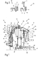
- an inventive torque transmission system 10 is shown. This includes two main system areas, namely on the one hand a constructed in the form of a dual mass flywheel torsional vibration damper 12 and on the other one here in the form of a double clutch 36 constructed friction clutch 14th
- the torsional vibration damper 12 has one with one shown drive shaft for common rotation to be firmly connected Primary side 16, which in the example shown, a disk part 18 with in radially outer region of the same carried primary flywheel 20 and a rotatably coupled with these two parts central disk element 22 has.
- Primary side 16 which in the example shown, a disk part 18 with in radially outer region of the same carried primary flywheel 20 and a rotatably coupled with these two parts central disk element 22 has.
- several helical compression springs comprehensive damper spring assembly 24 is with this primary side 16th a secondary side 26 coupled for torque transmission.
- the secondary side In the example shown, FIG. 26 includes two cover disk elements 28, 30, which, as well as the central disk element 22, support areas for provide the damper springs 24. In the radially outer area these are Cover disk elements 28, 30 firmly connected by riveting or the like and are further firmly connected to a connecting element 32.
- This connecting element 32 is in turn connected to a in The following explained in more detail input section 34 of the friction clutch 14 firmly connected.
- This torsional vibration damper 12 So is the torque generated at a drive shaft in the direction of Entrance area 34 of the friction clutch 14 transmitted.
- the friction clutch 14 is here as a double clutch 36 formed and includes as an input portion 34 is substantially one Intermediate plate 38, which is an abutment for the two coupling portions 40, 42 of the double clutch 36 forms. With this intermediate plate 38 is in not recognizable Way the connecting element 32 or possibly more in the circumferential direction around the axis of rotation A successively arranged fasteners 32 firmly connected by screwing or the like.
- the input portion 34 of the dual clutch 36 further includes a fixedly connected to the intermediate plate 38 housing 44 and in association to the two coupling portions 40, 42 each have a pressure plate 46, 48.
- the pressure plate 46 of the coupling portion 40 is for generating a state of engagement of this coupling portion 40 of a Kraftbeaufschlagungsan whatsoever 50 applied in the case of a coupling area 40 of the normally-closed type as a diaphragm spring or the like may be formed in the case of the construction of the coupling portion 40 after the normal-open principle, a plurality of substantially none own power contribution supplying lever elements may include.
- a plurality of substantially none own power contribution supplying lever elements may include.
- the engagement force of the Kraftbeaufleyungsan extract which is supported in its radially outer region on the housing 44 via a Verschl constitunachstellvorraum 52 passed to the pressure plate 46.
- the coupling portion 42 is also a Kraftbeaufschlagungsan whatsoever 44 associated with the construction of the normal-closed principle can be designed as an energy storage, wherein in the case of Double couplings in general but preferred structure according to the normal-open principle again comprise a plurality of lever elements can.
- the Kraftbeaufschlagungsan Aunt 54 is supported on the outside of the housing 44 and transmits the engagement force via a power transmission arrangement 56, which bridges the intermediate plate 38, to the pressure plate 48 of the coupling portion 42.
- This power transmission arrangement 56 comprises two substantially cup-shaped components 58, 60.
- both coupling portions 40, 42 are still basically the Entrance area 34 to be assigned pressure plates 46, 48 with the intermediate plate 38 and / or coupled to the housing 44 for common rotation, for example via tangential leaf springs or the like, the can also provide a release force for these pressure plates 46, 48.
- a clutch disc 64, 66 provided in association with each clutch area .
- Each of these clutch plates 64, 66 forms substantially then the exit area of the respective coupling area 40, 42 and is with one of two coaxial nested output shafts 68, 70th rotatably connected or connectable.
- the associated clutch disc 64 or 66 presses against the intermediate plate 38 is one of the coupling portions 40, 42 in a torque transmitting state during the other of the coupling areas then transmits no torque.
- actuating forces for the two coupling portions 40, 42 and the Both Kraftbeetzleyungsan effet 50, 54 thereof may in the case of clutch ranges of the normal-open type by conventional, known Actuation systems with coaxially graduated actuating cyles, Actuating forks or the like can be generated.
- a torque transmission system 10 may also be in such Be provided a wide variety of actuation systems, the specialist are common. Of importance to the present invention, however, is that, as symbolically indicated in Fig.
- This friction device 72 serves to a relative rotation between the primary side 16 and the secondary side 26 of the torsional vibration damper Counteract 12, i. at relative rotation Dissipate energy in the form of friction energy or heat energy, or with correspondingly large frictional force, the relative rotation to complete prevent and thus primary side 16 and secondary side 26 for to rigidly couple the common rotation.
- Torsional vibration damper have a resonance range, the - based on the speed of the torque transmission system - in one Range, which is chosen so that he does not drive in normal driving is going through. It can thus in driving by resonance excitation generated excessive torsional vibrations are avoided.
- FIG. 2 shows in its left half an active state of the friction device 72, ie a state in which this for generating a Frictional coupling between the primary side 16 and secondary side 26 is able to while the right side shows a deactivated state, ie a state in which such a friction effect is virtually impossible to produce.
- the in Fig. 2 in principle shown friction device 72 comprises a component a, which with a force F 'is applied.
- This force F ' is part of that of the already provided actuation system provided Operating force, ie in the present case engagement force F, on the Power transmission assembly 56 is introduced into the friction device 72.
- Another recognizable in Fig. 1 part F "of this engagement force F is on the Power transmission assembly 56 introduced into the pressure plate 48. Consequently the total operating force or total engagement force F is divided into the two force components F 'and F "(each taking into account the Lever transfer ratios), and the force component F 'is used at held in the active state friction device 72 to generate a frictional force
- component a is provided via an elasticity providing Component B, so for example a disc spring, a corrugated spring or the like, the force F 'introduced into an assembly c.
- this assembly c forms an assembly d a friction assembly c, d, the For example, 26 may be rotatably coupled to the secondary side.
- the friction assemblies c, d and e in frictional interaction brought so that the above-mentioned coupling effect between primary side 16 and secondary side 26 is generated.
- the curve or straight line g represents that over the closing path occurring course of the reaction force generated in the friction device 72, in Essentially provided or defined by the elasticity of the component b in Fig. 2. Therefore, in principle corresponds to the force g in Fig. 19 of the recognizable in Fig. 2 and introduced into the friction device 72 or in dependence force F 'to be initiated by the closing path.
- the actuation system that the Force F in the double clutch 36 and the coupling portion 42 initiates thus, in principle, the two forces F and G counteract, so that the Adjusting the coupling portion 42 in the closing direction from the Sum of forces f and g resulting total force K applied must become.
- the friction device 72 comprises two friction assemblies 74, 76.
- the first friction assembly 74 is basically the secondary side 26 of the torsional vibration damper 12 assign while the second friction assembly 76 of the primary side 16 is assigned.
- This second friction assembly 76 can For example, include the friction ring 78 shown in Figures 7 and 8, the over several radially outwardly cross-web portions 80 with the primary flywheel 20 is firmly connected.
- the friction assembly 74 includes also a friction ring 82, via a plate spring 84 or the like axially supported on the radially outer portion of the intermediate plate 38.
- the friction assembly 74 includes a plurality of circumferentially one another arranged following and on the component 60 of the power transmission arrangement 56 pivotally supported friction elements 86th This are, as seen in Fig. 5, approximately oriented in the circumferential direction and pivotable about pivot axes which are approximately parallel to the axis of rotation A of the torque transmission system 10 are.
- Each of these Friction elements 86 has a friction section 88 in its free end region on, with which this in frictional interaction with the axially following Friction ring 78 of the friction assembly 76 can be brought.
- each of the friction elements 86 designed here as a leg spring Biasing spring 90 is provided which on the friction element 86 on the one hand and on Part 60 of the power transmission assembly 56 on the other hand attacks to the Friction elements 86 to bias radially inward, ie in a state vorzuspannen, as in the bottom or left in Fig. 5 recognizable Friction elements 86 is present.
- the friction portion 88 is the Friction ring 78 positioned opposite, so that at appropriate Force introduction through the friction portions 88 of the friction elements 86 of the Friction ring 78 is pressed against the friction ring 82.
- the by the biasing spring 90 to be generated and the friction elements 86 radially biasing radially inward Force is to be dimensioned so that, for example, after passing through of critical area and turning at a speed above this critical area then the existing centrifugal force is sufficient to the Friction elements 86 against the biasing force generated by the biasing spring 90 to pivot radially outward, ie in the in Fig. 5th to swivel right and up recognizable state. In this condition if the respective friction section 88 is no longer aligned with the friction ring 78, as also illustrated in FIG. 4.
- the friction device 72 then again generates the actuating force F, so missing due to the Herausverschwenkens the friction elements 86 a Component area in the power transmission chain of the friction device 72, so that substantially no counterforce is generated in the friction device 72 and the entire operating force is then in the pressure plate 48th can be initiated.
- pivotal movement stops 92 may be provided for the friction elements 86, wherein these Schwenkambasanelle 92 at the same time the support of the biasing springs 90th can serve.
- the friction rings 78, 82 as has already been explained with reference to the friction ring 78, at least be segmented in the radially outer region.
- the plate spring 84 can have corresponding natural Bachsaussparungen, such Recesses in the circumferential direction should be dimensioned such that at the maximum possible relative rotation between the primary side 16 and the secondary side 26 a mutual interference with the connecting element 32 can not occur. Basically, it is also possible, as in the Fig.
- the friction device 72 When reaching the idle speed can then, as above described, the friction device 72 by canceling the operating force F and by allowing centrifugal pivoting of the Friction elements 86 are brought into the deactivated state.
- first Care is taken that the friction device 72 reach its active state can, for example, by canceling the Betreliistskrafterzeugung at the coupling portion 42, if not already, and then by re-generating the operating force F, the friction device 72 also is brought into the frictional state, so that both the fall in the speed and thus passing through the critical area, as well as for the next one Start operation, the friction device 72 is in the active state.
- both Clutch areas 40, 42 provide such friction devices, so that always at that clutch area, at which moment no torque is to be transmitted, by appropriate actuation force transmission or generating a friction torque can be generated, which is a specific Extent of coupling between primary side 16 and secondary side 26 guaranteed. It can thus, for example, an active vibration damping be operated or taken care that in certain Operating conditions the occurrence of torsional vibrations by reinforced Frictional action is counteracted. Because this means that with both Coupling portions 40, 42 at the same time an actuating force is generated, Make sure that only in assignment to one of the coupling areas a gear is engaged.
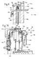
- FIG. 9 An alternative embodiment of the friction device is shown in FIG. 9.
- Fig. 9 which only a partial section of that shown in Fig. 1
- Overall arrangement shows are components which in terms of structure or Function previously described components correspond, with the same reference number with the addition of an Annex "a" designated.
- the friction elements 86a of the first friction assembly 74a via axle components 94a on the pressure plate 84a which means that these friction elements 86a basically can be assigned to the secondary side again.
- the friction ring 78a of the friction assembly 76a can, as described above, again at the Be born primary mass of the torsional vibration damper.
- the friction elements 86a on the other side of the friction ring 78a is directly the radially outer portion 96a of the intermediate plate 38a, which now provides a part of the first friction assembly 74a.
- a force introduction element 98a is provided, via the plate spring 84a can act on the friction elements 86a.
- This force introduction element 98a may be fixed to the part 60a of the power transmission assembly 56a but can also be separated from this part 60a directly with the associated Kraftbeetzstoffsan 11, so the lever elements thereof or possibly spring tongues of a diaphragm spring or the like, interact, to obtain the required axial displacement.
- the pressure plate 48a when wear occurs in the area the clutch disc 66a is closer to the intermediate plate 38a care must be taken that appropriate Space between the force input element 98a and the radially outer Area of the pressure plate 48 a is maintained.
- FIGS. 10 to 12 Another embodiment of a torque transmission system will be described below with reference to FIGS. 10 to 12.
- Components which components described above in terms Structure and function correspond are denoted by the same reference numerals with the addition of Annex "b". Because of the construction of the torsional vibration damper and the friction clutch in Substantial correspondences with the embodiment according to FIG. 1 is in this respect, to the previous versions directed.
- Friction ring 78b of the second friction assembly 76b to the primary side 16b of Torsional vibration damper coupled.
- several pen or bolt-like connecting links 100b may be provided which either are passed radially outside of the intermediate plate 38b, or in this and also in the connecting element 32b provided circumferential recesses push through.
- the friction elements 86b of the first friction assembly 74b are on a radially outwardly extending portion 102b of the Housing 44b pivotally supported and by the respectively associated Springs 90b biased radially inward, ie in a state prestressed, in which they become frictionally effective.
- the torsional vibration damper 12c Here is designed as a so-called wet-running vibration damper.
- the primary side 16c attributable shroud elements 28c, 30c form a radially outwardly fluid-tight sealed chamber, in which the damper springs 24 c are arranged and further a viscous medium may be provided, on the one hand another damping component on the other hand provide lubrication to be able to.
- On the cover disk element 28c is in the radially outer Area the primary mass 20c worn.
- the actuation system While in a clutch or a coupling region of the Normal-open type, the actuation system by appropriate Actuator control generates engagement forces, the engagement force is at a Actuation system for a clutch of the normal-closed type by provided the power storage, while then a release force by a Actuator or manually generate.
- friction portions 88c thereof is located on the housing 44c and this set on the secondary mass 106c screw bolt 120c itself supporting friction ring 78c of the second friction assembly 76c.
- the pressure plate 108c acted upon act at the same time the Beaufschlagungsabête 116 c which these respectively assigned Friction elements 86c, the spring-biased at insufficient speed are pivoted radially inward.
- FIG. 16 shows an urging portion 116c, in which at both peripheral edge regions axially projecting securing walls 124c present are.
- a relative circumferential movement would have one positive holding action between the friction elements 86c and the side each arranged securing walls 124c result.
- at the variant shown in Fig. 17 is at the radially outer portion of the loading portion 116c is a circumferentially extending Backup wall 126c provided which the friction element of radial can overlap axially outside and thus from the outside radially a frictional interaction or / and a form-fitting interaction with the Can produce friction element 86c.
- the friction clutch 14c shown in Fig. 13 may be for manual operation be provided. That is, it is to be provided by a driver that the friction device 72c for the required phases in their active state is brought. This may be the same as the ones described above automated systems, done so that, for example, before the Starting the Antriesbsaggregats the driver once the clutch, to allow the pivoting of the friction elements 86c radially inward. After the driver then released the clutch pedal again has and the clutch is engaged again, then the drive unit to be started. To provide increased security here, the Actuating state of the clutch can be sensed, so that only then, once the disengagement and re-engagement of the clutch is made has been recorded and has been recorded accordingly, the drive unit is released to perform the boot process.
- an inventively designed torque transmission system is due to the possibility of the friction between an active state and disabling a disabling state, making sure that these together with a friction clutch or a clutch area the same can be actuated, only if the friction clutch in its active state is a part of the actuation force for Reibrohfterzeugung is used, while with deactivated friction the full operating force in the friction clutch or a clutch area the same can flow.
- none over normal Force range, which is required for the actuation of the friction clutch, going beyond Forces also need to be generated to include the friction device to be able to bring into the frictional state.
- the friction device is in the range of operation required for the friction clutch between her completely indented and her completely disengaged Condition to be adjusted, mitbetätigt. This simplifies the overall structure and in particular the structure of the actuation systems, provided that Actuation is automated, as these are then not excessively large must be dimensioned.
- the forces to adjust the friction clutch between its active state and its deactivated state generated in a manner other than described above can be. It can of course other biasing or spring elements be provided. Furthermore, the forces can also be, for example be generated by electromagnetic means, so that an adjustment the friction elements not only in response to the changing speed state can be made, but also active depending on other parameters, the friction between its active state and their deactivation state can be adjusted.
- an energy storage such as diaphragm spring or the like, which ultimately together with those System areas that act on the energy storage Serve providing the total actuation system with which the clutch adjusted between an engagement state and a disengagement state can be.
Landscapes
- Engineering & Computer Science (AREA)
- General Engineering & Computer Science (AREA)
- Physics & Mathematics (AREA)
- Acoustics & Sound (AREA)
- Aviation & Aerospace Engineering (AREA)
- Mechanical Engineering (AREA)
- Mechanical Operated Clutches (AREA)
Abstract
Description
- Fig. 1
- eine Teil-Längsschnittansicht eines erfindungsgemäßen Drehmomentübertragungssystems;
- Fig. 2
- eine Prinzipdarstellung einer bei dem Drehmomentübertragungssystem der Fig. 1 eingesetzten Reibeinrichtung zum Erklären der wesentlichen Prinzipien der Erfindung;
- Fig. 3
- eine Detailansicht des Systems der Fig. 1 in einem Aktivzustand der Reibeinrichtung;
- Fig. 4
- eine der Fig. 3 entsprechende Ansicht in einem Deaktivzustand der Reibeinrichtung,
- Fig. 5
- eine Prinzip-Axialansicht der bei der Ausgestaltungsform gemäß den Figuren 1 bis 4 eingesetzten Reibeinrichtung;
- Fig. 6
- eine Schnittansicht eines bei der Reibeinrichtung eingesetzten schwenkbaren Reibbauteils;
- Fig. 7
- eine Axialansicht eines bei der Reibeinrichtung eingesetzten Reibrings;
- Fig. 8
- eine Schnittansicht des Reibrings der Fig. 7;
- Fig. 9
- eine Abwandlung des in Fig. 1 gezeigten Systems;
- Fig. 10
- eine weitere erfindungsgemäße Ausgestaltungsform eines Drehmomentübertragungssystems;
- Fig. 11
- eine Detailansicht des Systems der Fig. 10 in einem Aktivzustand der Reibeinrichtung;
- Fig. 12
- eine der Fig. 11 entsprechende Ansicht in einem Deaktivzustand der Reibeinrichtung;
- Fig. 13
- ein weiteres erfindungsgemäß ausgestaltetes Drehmomentübertragungssystem;
- Fig. 14
- eine Draufsicht auf einen Kraftspeicher des in Fig. 13 gezeigten Systems;
- Fig. 15
- eine Abwandlung des in Fig. 14 gezeigten Kraftspeichers;
- Fig. 16
- eine Teil-Radialansicht des in Fig. 15 gezeigten Kraftspeichers in Blickrichtung XVI in Fig. 15;
- Fig. 17
- eine Teil-Schnittansicht des in Fig. 15 gezeigten Kraftspeichers geschnitten längs einer Linie XVII-XVII in Fig. 15;
- Fig. 18
- eine Detailansicht eines bei der Ausgestaltungsform der Fig. 13 eingesetzten schwenkbaren Reibbauteils;
- Fig. 19
- ein Diagramm, das den Zusammenhang der bei einem Betätigungssystem bereitzustellenden Anpresskraft in Abhängigkeit von dem Schließweg zeigt.
Claims (17)
- Drehmomentübertragungssystem, umfassend:dadurch gekennzeichnet, dass die Reibeinrichtung (72; 72a; 72b; 72c) zwischen einem Aktivzustand und einem Deaktivzustand umschaltbar ist, so dass bei Beaufschlagung der Reibeinrichtung (72; 72a; 72b; 72c) durch das Betätigungssystem im Aktivzustand die Reibungskopplung zwischen Primärseite (16; 16b; 16c) und Sekundärseite (26; 26b; 26c) erzeugbar ist und bei Beaufschlagung der Reibeinrichtung (72; 72a; 72b; 72c) durch das Betätigungssystem im Deaktivzustand im Wesentlichen keine Reibungskopplung zwischen Primärseite (16; 16b; 16c) und Sekundärseite (26; 26b; 26c) erzeugbar ist.eine Schwingungsdämpfungsanordnung (12; 12b; 12c) mit einer mit einem Antriebsorgan zur Drehung um eine Drehachse (A) zu koppelnden Primärseite (16; 16a; 16b; 16c), einer gegen die Wirkung einer Dämpferfederanordnung (24; 24b; 24c) bezüglich der Primärseite (16; 16b; 16c) um die Drehachse (A) drehbaren Sekundärseite (26; 26b; 26c) und einer Reibeinrichtung (72; 72a; 72b; 72c) zur Erzeugung einer Reibungskopplung zwischen Primärseite (16; 16b; 16c) und Sekundärseite (26; 26b; 26c),eine Reibungskupplung (14; 14a; 14b; 14c) an der Sekundärseite (26; 26b; 26c) der Schwingungsdämpfungsanordnung (12; 12b; 12c),ein Betätigungssystem zur Erzeugung einer Betätigungskraft (F) zur Betätigung der Reibungskupplung (14; 14a; 14b; 14c) zwischen einem Einrückzustand und einem Ausrückzustand und zur Betätigung der Reibeinrichtung (72; 72a; 72b; 72c),
- Drehmomentübertragungssystem nach Anspruch 1,
dadurch gekennzeichnet, dass die Reibeinrichtung (72; 72a; 72b; 72c) eine mit der Primärseite (16; 16b; 16c) gekoppelte erste Reibbaugruppe (74; 74a; 74b; 74c) und eine mit der Sekundärseite (26; 26b; 26c) gekoppelte zweite Reibbaugruppe (76; 76a; 76b; 76c) aufweist, wobei im Aktivzustand der Reibeinrichtung (72; 72a; 72b; 72c) durch Betätigungskraftbeaufschlagung vermittels des Betätigungssystems eine Reibwechselwirkung zwischen der ersten Reibbaugruppe (74; 74a; 74b; 74c) und der zweiten Reibbaugruppe (76; 76a; 76b; 76c) erzeugbar ist, und dass wenigstens eine Reibbaugruppe von erster Reibbaugruppe (74; 74a; 74b; 74c) und zweiter Reibbaugruppe (76; 76a; 76b; 76c) wenigstens ein Baugruppenelement (86; 86a; 86b; 86c) umfasst, das zum Umschalten der Reibeinrichtung (72; 72a; 72b; 72c) zwischen dem Aktivzustand und dem Deaktivzustand verstellbar ist. - Drehmomentübertragungssystem nach Anspruch 2,
dadurch gekennzeichnet, dass das eine Baugruppenelement (86; 86a; 86b; 86c) zwischen einem ersten Stellzustand, in welchem es eine Reibwechselwirkung der einen Reibbaugruppe mit der anderen Reibbaugruppe bewirken kann, und einem zweiten Stellzustand, in welchem es im Wesentlichen keine Reibwechselwirkung der einen Reibbaugruppe mit der anderen Reibbaugruppe bewirken kann, verstellbar ist. - Drehmomentübertragungssystem nach Anspruch 3,
dadurch gekennzeichnet, dass das wenigstens eine Baugruppenelement (86; 86a; 86b; 86c) an der mit der einen Reibbaugruppe gekoppelten Seite von Primärseite (16; 16b; 16c) und Sekundärseite (26; 26b; 26c) zwischen dem ersten Stellzustand und dem zweiten Stellzustand verschwenkbar getragen ist. - Drehmomentübertragungssystem nach Anspruch 3 oder 4,
dadurch gekennzeichnet, dass das wenigstens eine Baugruppenelement (86; 86a; 86b; 86c) in einen Stellzustand von erstem Stellzustand und zweitem Stellzustand vorgespannt ist und durch Stellkrafteinwirkung in den anderen Stellzustand verstellbar ist. - Drehmomentübertragungssystem nach Anspruch 5,
dadurch gekennzeichnet, dass eine Vorspannfeder (90; 90b; 90c) zum Vorspannen des wenigstens einen Baugruppenelements (86; 86a; 86b; 86c) in den einen Stellzustand vorgesehen ist. - Drehmomentübertragungssystem nach Anspruch 5 oder 6,
dadurch gekennzeichnet, dass die Stellkrafteinwirkung durch Fliehkrafteinwirkung erfolgt. - Drehmomentübertragungssystem nach einem der Ansprüche 1 bis 7,
dadurch gekennzeichnet, dass der eine Stellzustand der erste Stellzustand ist. - Drehmomentübertragungssystem nach einem der Ansprüche 5 bis 8,
dadurch gekennzeichnet, dass Vorspannung und Stellkrafteinwirkung derart aufeinander abgestimmt sind, dass bei Erreichen einer vorbestimmten Drehzahl oder eines vorbestimmten Drehzahlbereichs ein Verstellen des wenigstens einen Baugruppenelements (86; 86a; 86b; 86c) zwischen dem ersten Stellzustand und dem zweiten Stellzustand erfolgen kann. - Drehmomentübertragungssystem nach Anspruch 7 und Anspruch 9,
dadurch gekennzeichnet, dass bei Erhöhen der Drehzahl die Vorspannung bis zum Erreichen der vorbestimmten Drehzahl oder des vorbestimmten Drehzahlbereichs die Fliehkrafteinwirkung wenigstens bereichsweise kompensiert. - Drehmomentübertragungssystem nach einem der Ansprüche 1 bis 10,
dadurch gekennzeichnet, dass bei Erzeugung einer Betätigungskraft durch das Betätigungssystem zum Verstellen der Reibungskupplung zwischen dem Einrückzustand und dem Ausrückzustand ein erster Teil der Betätigungskraft als Einrückkraft wirksam ist und ein zweiter Teil der Betätigungskraft als Reibeinrichtungsbetätigungskraft wirksam ist. - Drehmomentübertragungssystem nach Anspruch 2 oder einem der Ansprüche 3 bis 11, sofern auf Anspruch 2 rückbezogen,
dadurch gekennzeichnet, dass die andere Reibbaugruppe ein ringartiges Reibelement (78; 78a; 78b; 78c) umfasst und dass das wenigstens eine Baugruppenelement (86; 86a; 86b; 86c) durch das Betätigungssystem bei Betätigungskrafterzeugung in Reibwechselwirkung mit dem ringartigen Reibelement (78; 78a; 78b; 78c) bringbar ist. - Drehmomentübertragungssystem nach Anspruch 12,
dadurch gekennzeichnet, dass die eine Reibbaügruppe eine Mehrzahl von in Umfangsrichtung aufeinander folgend angeordneten Baugruppenelementen (86; 86a; 86b; 86c) aufweist. - Drehmomentübertragungssystem nach Anspruch 12 oder 13,
dadurch gekennzeichnet, dass die eine Reibbaugruppe an einer ersten Seite des ringartigen Reibelements (78; 78a; 78b) der anderen Reibbaugruppe das wenigstens eine Baugruppenelement (86; 86a; 86b) aufweist und an einer zweiten Seite des ringartigen Reibelements (78; 78a; 78b) wenigstens ein Widerlagerreibelement (82; 96a; 84b) aufweist. - Drehmomentübertragungssystem nach Anspruch 2 oder einem der Ansprüche 3 bis 14, sofern auf Anspruch 2 rückbezogen,
dadurch gekennzeichnet, dass die Reibeinrichtung (72; 72a; 72b; 72c) im Abstützweg der Betätigungskraft ein elastisches Element (84; 84a; 84b) umfasst. - Drehmomentübertragungssystem nach einem der Ansprüche 1 bis 15,
dadurch gekennzeichnet, dass die Reibungskupplung (14; 14b) eine Doppelkupplung (36; 36b) ist mit einem ersten Kupplungsbereich (40; 40b) und einem zweiten Kupplungsbereich (42; 42b) und dass die Reibeinrichtung (72; 72b) einen ersten Reibeinrichtungsbereich (72b) aufweist, der bei Betätigungskrafterzeugung durch das Betätigungssystem für den ersten Kupplungsbereich (40b) die Reibungskopplung zwischen Primärseite (16b) und Sekundärseite (26b) erzeugen kann oder/und einen zweiten Reibeinrichtungsbereich (72) umfasst, der bei Betätigungskrafterzeugung durch das Betätigungssystem für den zweiten Kupplungsbereich (42) die Reibungskopplung zwischen Primärseite (16) und Sekundärseite (26) erzeugen kann. - Drehmomentübertragungssystem, umfassend:dadurch gekennzeichnet, dass bei Erzeugung einer Betätigungskraft durch das Betätigungssystem zum Verstellen der Reibungskupplung (14; 14a; 14b; 14c) zwischen dem Einrückzustand und dem Ausrückzustand ein erster Teil der Betätigungskraft als Einrückkraft wirksam ist und ein zweiter Teil der Betätigungskraft als Reibeinrichtungsbetätigungskraft wirksam ist.eine Schwingungsdämpfungsanordnung (12; 12b; 12c) mit einer mit einem Antriebsorgan zur Drehung um eine Drehachse (A) zu koppelnden Primärseite (16; 16a; 16b; 16c), einer gegen die Wirkung einer Dämpferfederanordnung (24; 24b; 24c) bezüglich der Primärseite (16; 16b; 16c) um die Drehachse (A) drehbaren Sekundärseite (26; 26b; 26c) und einer Reibeinrichtung (72; 72a; 72b; 72c) zur Erzeugung einer Reibungskopplung zwischen Primärseite (16; 16b; 16c) und Sekundärseite (26; 26b; 26c),eine Reibungskupplung (14; 14a; 14b; 14c) an der Sekundärseite (26; 26b; 26c) der Schwingungsdämpfungsanordnung (12; 12b; 12c),ein Betätigungssystem zur Erzeugung einer Betätigungskraft (F) zur Betätigung der Reibungskupplung (14; 14a; 14b; 14c) zwischen einem Einrückzustand und einem Ausrückzustand und zur Betätigung der Reibeinrichtung (72; 72a; 72b; 72c),
Applications Claiming Priority (2)
| Application Number | Priority Date | Filing Date | Title |
|---|---|---|---|
| DE10355531 | 2003-11-27 | ||
| DE2003155531 DE10355531A1 (de) | 2003-11-27 | 2003-11-27 | Drehmomentübertragungssystem |
Publications (2)
| Publication Number | Publication Date |
|---|---|
| EP1548324A1 true EP1548324A1 (de) | 2005-06-29 |
| EP1548324B1 EP1548324B1 (de) | 2007-01-10 |
Family
ID=34530319
Family Applications (1)
| Application Number | Title | Priority Date | Filing Date |
|---|---|---|---|
| EP20040027356 Expired - Fee Related EP1548324B1 (de) | 2003-11-27 | 2004-11-18 | Drehmomentübertragungssystem |
Country Status (2)
| Country | Link |
|---|---|
| EP (1) | EP1548324B1 (de) |
| DE (2) | DE10355531A1 (de) |
Cited By (2)
| Publication number | Priority date | Publication date | Assignee | Title |
|---|---|---|---|---|
| WO2016162025A1 (de) * | 2015-04-09 | 2016-10-13 | Schaeffler Technologies AG & Co. KG | Drehschwingungsdämpfer |
| DE102015009133A1 (de) * | 2015-07-09 | 2017-01-12 | Borgwarner Inc. | Dämpfungsanordnung für den Antriebsstrang eines Kraftfahrzeugs |
Families Citing this family (1)
| Publication number | Priority date | Publication date | Assignee | Title |
|---|---|---|---|---|
| DE102015220920B4 (de) * | 2014-12-15 | 2023-02-16 | Schaeffler Technologies AG & Co. KG | Baugruppe mit einer Reibeinrichtung |
Citations (6)
| Publication number | Priority date | Publication date | Assignee | Title |
|---|---|---|---|---|
| DE3418671A1 (de) * | 1983-10-24 | 1985-05-09 | LuK Lamellen und Kupplungsbau GmbH, 7580 Bühl | Daempfungseinrichtung zum aufnehmen bzw. ausgleichen von drehstoessen |
| DE3627784A1 (de) * | 1986-08-16 | 1987-07-02 | Daimler Benz Ag | Geteiltes schwungrad |
| DE3941251A1 (de) * | 1988-12-24 | 1990-06-28 | Luk Lamellen & Kupplungsbau | Einrichtung zum daempfen von schwingungen |
| DE19519363A1 (de) * | 1994-07-15 | 1996-01-25 | Fichtel & Sachs Ag | Geteilte Schwungradvorrichtung |
| DE3448479C2 (de) * | 1983-10-24 | 1999-09-23 | Luk Lamellen & Kupplungsbau | Dämpfungseinrichtung |
| DE10231766A1 (de) * | 2001-10-09 | 2003-04-10 | Zf Sachs Ag | Reibungskupplungsanordnung |
-
2003
- 2003-11-27 DE DE2003155531 patent/DE10355531A1/de not_active Withdrawn
-
2004
- 2004-11-18 DE DE200450002611 patent/DE502004002611D1/de active Active
- 2004-11-18 EP EP20040027356 patent/EP1548324B1/de not_active Expired - Fee Related
Patent Citations (6)
| Publication number | Priority date | Publication date | Assignee | Title |
|---|---|---|---|---|
| DE3418671A1 (de) * | 1983-10-24 | 1985-05-09 | LuK Lamellen und Kupplungsbau GmbH, 7580 Bühl | Daempfungseinrichtung zum aufnehmen bzw. ausgleichen von drehstoessen |
| DE3448479C2 (de) * | 1983-10-24 | 1999-09-23 | Luk Lamellen & Kupplungsbau | Dämpfungseinrichtung |
| DE3627784A1 (de) * | 1986-08-16 | 1987-07-02 | Daimler Benz Ag | Geteiltes schwungrad |
| DE3941251A1 (de) * | 1988-12-24 | 1990-06-28 | Luk Lamellen & Kupplungsbau | Einrichtung zum daempfen von schwingungen |
| DE19519363A1 (de) * | 1994-07-15 | 1996-01-25 | Fichtel & Sachs Ag | Geteilte Schwungradvorrichtung |
| DE10231766A1 (de) * | 2001-10-09 | 2003-04-10 | Zf Sachs Ag | Reibungskupplungsanordnung |
Cited By (2)
| Publication number | Priority date | Publication date | Assignee | Title |
|---|---|---|---|---|
| WO2016162025A1 (de) * | 2015-04-09 | 2016-10-13 | Schaeffler Technologies AG & Co. KG | Drehschwingungsdämpfer |
| DE102015009133A1 (de) * | 2015-07-09 | 2017-01-12 | Borgwarner Inc. | Dämpfungsanordnung für den Antriebsstrang eines Kraftfahrzeugs |
Also Published As
| Publication number | Publication date |
|---|---|
| EP1548324B1 (de) | 2007-01-10 |
| DE502004002611D1 (de) | 2007-02-22 |
| DE10355531A1 (de) | 2005-06-23 |
Similar Documents
| Publication | Publication Date | Title |
|---|---|---|
| EP1499811B1 (de) | Kupplungsaggregat | |
| EP1851460B1 (de) | Kupplungsaggregat | |
| EP1479934B1 (de) | Antriebsstrang | |
| EP2050608B1 (de) | Antriebssystem für ein Fahrzeug | |
| DE10016607B4 (de) | Doppelkupplungsanordnung | |
| EP1862689B1 (de) | Drehmomentübertragungsanordnung für den Antriebsstrang eines Fahrzeugs | |
| EP1134447B1 (de) | Doppelkupplungsanordnung | |
| EP3198160A1 (de) | Zuschaltkupplung für hybriden antriebsstrang mit momentenfühler | |
| WO2003029677A1 (de) | Mehrfachkupplungsanordnung, insbesondere doppelkupplungsanordnung | |
| EP2326852B1 (de) | Antriebstrang mit einer doppelkupplung | |
| DE102014211884A1 (de) | Blattfeder für ein Mehrscheibenreibpaket und Mehrscheibenreibpaket für eine Reibkupplung | |
| EP1302687B1 (de) | Mehrfach-Kupplungsanordnung | |
| EP1413795B2 (de) | Drehmomentübertragungsanordnung | |
| EP2000698B1 (de) | Torsionsschwingungsdämpfer | |
| EP1400716B1 (de) | Kupplungssystem und Halteanordnung zum Halten wenigstens einer Kupplungsanordnung des Kupplungssystems in einem momentanen oder vorgegebenen Einrückzustand | |
| EP1862688B2 (de) | Drehmomentübertragungsanordnung für den Antriebsstrang eines Fahrzeugs | |
| EP1548324B1 (de) | Drehmomentübertragungssystem | |
| DE10241027A1 (de) | Mehrfach-Kupplungsanordnung | |
| EP1862685A1 (de) | Drehmomentübertragungsanordnung für den Antriebsstrang eines Fahrzeugs | |
| EP3875796B1 (de) | Form- und reibschlüssige kupplung | |
| EP3649362A1 (de) | Antriebsstranganordnung sowie kraftfahrzeug | |
| WO2017140535A1 (de) | Kupplungsanordnung mit schwingungsdämpfer und fahrzeugantriebsstrang | |
| WO2004003399A1 (de) | Antriebssystem für ein fahrzeug | |
| DE10049475A1 (de) | Reibungskupplung | |
| WO2019007461A1 (de) | Reibkupplung |
Legal Events
| Date | Code | Title | Description |
|---|---|---|---|
| PUAI | Public reference made under article 153(3) epc to a published international application that has entered the european phase |
Free format text: ORIGINAL CODE: 0009012 |
|
| 17P | Request for examination filed |
Effective date: 20050216 |
|
| AK | Designated contracting states |
Kind code of ref document: A1 Designated state(s): AT BE BG CH CY CZ DE DK EE ES FI FR GB GR HU IE IS IT LI LU MC NL PL PT RO SE SI SK TR |
|
| AX | Request for extension of the european patent |
Extension state: AL HR LT LV MK YU |
|
| AKX | Designation fees paid |
Designated state(s): DE FR GB |
|
| GRAP | Despatch of communication of intention to grant a patent |
Free format text: ORIGINAL CODE: EPIDOSNIGR1 |
|
| GRAS | Grant fee paid |
Free format text: ORIGINAL CODE: EPIDOSNIGR3 |
|
| GRAA | (expected) grant |
Free format text: ORIGINAL CODE: 0009210 |
|
| AK | Designated contracting states |
Kind code of ref document: B1 Designated state(s): DE FR GB |
|
| REG | Reference to a national code |
Ref country code: GB Ref legal event code: FG4D Free format text: NOT ENGLISH |
|
| REF | Corresponds to: |
Ref document number: 502004002611 Country of ref document: DE Date of ref document: 20070222 Kind code of ref document: P |
|
| GBT | Gb: translation of ep patent filed (gb section 77(6)(a)/1977) |
Effective date: 20070330 |
|
| ET | Fr: translation filed | ||
| PLBE | No opposition filed within time limit |
Free format text: ORIGINAL CODE: 0009261 |
|
| STAA | Information on the status of an ep patent application or granted ep patent |
Free format text: STATUS: NO OPPOSITION FILED WITHIN TIME LIMIT |
|
| 26N | No opposition filed |
Effective date: 20071011 |
|
| PGFP | Annual fee paid to national office [announced via postgrant information from national office to epo] |
Ref country code: FR Payment date: 20081112 Year of fee payment: 5 |
|
| PGFP | Annual fee paid to national office [announced via postgrant information from national office to epo] |
Ref country code: GB Payment date: 20081112 Year of fee payment: 5 |
|
| GBPC | Gb: european patent ceased through non-payment of renewal fee |
Effective date: 20091118 |
|
| REG | Reference to a national code |
Ref country code: FR Ref legal event code: ST Effective date: 20100730 |
|
| PG25 | Lapsed in a contracting state [announced via postgrant information from national office to epo] |
Ref country code: FR Free format text: LAPSE BECAUSE OF NON-PAYMENT OF DUE FEES Effective date: 20091130 |
|
| PG25 | Lapsed in a contracting state [announced via postgrant information from national office to epo] |
Ref country code: GB Free format text: LAPSE BECAUSE OF NON-PAYMENT OF DUE FEES Effective date: 20091118 |
|
| PGFP | Annual fee paid to national office [announced via postgrant information from national office to epo] |
Ref country code: DE Payment date: 20121114 Year of fee payment: 9 |
|
| PG25 | Lapsed in a contracting state [announced via postgrant information from national office to epo] |
Ref country code: DE Free format text: LAPSE BECAUSE OF NON-PAYMENT OF DUE FEES Effective date: 20140603 |
|
| REG | Reference to a national code |
Ref country code: DE Ref legal event code: R119 Ref document number: 502004002611 Country of ref document: DE Effective date: 20140603 |