EP1548313A2 - Torque transmission device and drive train comprising such a device - Google Patents
Torque transmission device and drive train comprising such a device Download PDFInfo
- Publication number
- EP1548313A2 EP1548313A2 EP04029777A EP04029777A EP1548313A2 EP 1548313 A2 EP1548313 A2 EP 1548313A2 EP 04029777 A EP04029777 A EP 04029777A EP 04029777 A EP04029777 A EP 04029777A EP 1548313 A2 EP1548313 A2 EP 1548313A2
- Authority
- EP
- European Patent Office
- Prior art keywords
- friction
- transmission device
- torque transmission
- clutch
- torque
- Prior art date
- Legal status (The legal status is an assumption and is not a legal conclusion. Google has not performed a legal analysis and makes no representation as to the accuracy of the status listed.)
- Granted
Links
- 230000005540 biological transmission Effects 0.000 title claims abstract description 169
- 238000002485 combustion reaction Methods 0.000 claims abstract description 18
- 230000009977 dual effect Effects 0.000 claims description 35
- 230000008878 coupling Effects 0.000 claims description 29
- 238000010168 coupling process Methods 0.000 claims description 29
- 238000005859 coupling reaction Methods 0.000 claims description 29
- 239000002826 coolant Substances 0.000 claims description 21
- 238000004146 energy storage Methods 0.000 claims description 21
- 238000001816 cooling Methods 0.000 claims description 13
- 230000000295 complement effect Effects 0.000 claims description 2
- 230000006835 compression Effects 0.000 claims description 2
- 238000007906 compression Methods 0.000 claims description 2
- 230000001419 dependent effect Effects 0.000 claims description 2
- 230000001105 regulatory effect Effects 0.000 claims description 2
- 238000007789 sealing Methods 0.000 claims 1
- 239000002184 metal Substances 0.000 description 9
- 238000006073 displacement reaction Methods 0.000 description 7
- 230000000694 effects Effects 0.000 description 4
- 230000009471 action Effects 0.000 description 2
- 230000009286 beneficial effect Effects 0.000 description 2
- 238000010276 construction Methods 0.000 description 2
- 230000001276 controlling effect Effects 0.000 description 2
- 238000010586 diagram Methods 0.000 description 2
- 238000007373 indentation Methods 0.000 description 2
- 239000000314 lubricant Substances 0.000 description 2
- 238000004519 manufacturing process Methods 0.000 description 2
- 238000000034 method Methods 0.000 description 2
- 230000008569 process Effects 0.000 description 2
- 238000003860 storage Methods 0.000 description 2
- 241001295925 Gegenes Species 0.000 description 1
- 241000446313 Lamella Species 0.000 description 1
- 229910000639 Spring steel Inorganic materials 0.000 description 1
- 230000008901 benefit Effects 0.000 description 1
- 150000001875 compounds Chemical class 0.000 description 1
- 238000013016 damping Methods 0.000 description 1
- 238000005265 energy consumption Methods 0.000 description 1
- 210000003746 feather Anatomy 0.000 description 1
- 238000007667 floating Methods 0.000 description 1
- 239000002783 friction material Substances 0.000 description 1
- 230000006872 improvement Effects 0.000 description 1
- 238000009434 installation Methods 0.000 description 1
- 230000010354 integration Effects 0.000 description 1
- 238000005304 joining Methods 0.000 description 1
- 239000007788 liquid Substances 0.000 description 1
- 238000005461 lubrication Methods 0.000 description 1
- 239000000463 material Substances 0.000 description 1
- 239000012528 membrane Substances 0.000 description 1
- 230000036316 preload Effects 0.000 description 1
- 238000003825 pressing Methods 0.000 description 1
- 238000005086 pumping Methods 0.000 description 1
- 230000003014 reinforcing effect Effects 0.000 description 1
- 238000005096 rolling process Methods 0.000 description 1
- 239000011232 storage material Substances 0.000 description 1
- 210000002105 tongue Anatomy 0.000 description 1
Images


Classifications
-
- F—MECHANICAL ENGINEERING; LIGHTING; HEATING; WEAPONS; BLASTING
- F16—ENGINEERING ELEMENTS AND UNITS; GENERAL MEASURES FOR PRODUCING AND MAINTAINING EFFECTIVE FUNCTIONING OF MACHINES OR INSTALLATIONS; THERMAL INSULATION IN GENERAL
- F16D—COUPLINGS FOR TRANSMITTING ROTATION; CLUTCHES; BRAKES
- F16D48/00—External control of clutches
- F16D48/02—Control by fluid pressure
-
- F—MECHANICAL ENGINEERING; LIGHTING; HEATING; WEAPONS; BLASTING
- F16—ENGINEERING ELEMENTS AND UNITS; GENERAL MEASURES FOR PRODUCING AND MAINTAINING EFFECTIVE FUNCTIONING OF MACHINES OR INSTALLATIONS; THERMAL INSULATION IN GENERAL
- F16H—GEARING
- F16H45/00—Combinations of fluid gearings for conveying rotary motion with couplings or clutches
- F16H45/02—Combinations of fluid gearings for conveying rotary motion with couplings or clutches with mechanical clutches for bridging a fluid gearing of the hydrokinetic type
-
- F—MECHANICAL ENGINEERING; LIGHTING; HEATING; WEAPONS; BLASTING
- F16—ENGINEERING ELEMENTS AND UNITS; GENERAL MEASURES FOR PRODUCING AND MAINTAINING EFFECTIVE FUNCTIONING OF MACHINES OR INSTALLATIONS; THERMAL INSULATION IN GENERAL
- F16D—COUPLINGS FOR TRANSMITTING ROTATION; CLUTCHES; BRAKES
- F16D21/00—Systems comprising a plurality of actuated clutches
- F16D21/02—Systems comprising a plurality of actuated clutches for interconnecting three or more shafts or other transmission members in different ways
- F16D21/06—Systems comprising a plurality of actuated clutches for interconnecting three or more shafts or other transmission members in different ways at least two driving shafts or two driven shafts being concentric
-
- F—MECHANICAL ENGINEERING; LIGHTING; HEATING; WEAPONS; BLASTING
- F16—ENGINEERING ELEMENTS AND UNITS; GENERAL MEASURES FOR PRODUCING AND MAINTAINING EFFECTIVE FUNCTIONING OF MACHINES OR INSTALLATIONS; THERMAL INSULATION IN GENERAL
- F16D—COUPLINGS FOR TRANSMITTING ROTATION; CLUTCHES; BRAKES
- F16D25/00—Fluid-actuated clutches
- F16D25/08—Fluid-actuated clutches with fluid-actuated member not rotating with a clutching member
-
- F—MECHANICAL ENGINEERING; LIGHTING; HEATING; WEAPONS; BLASTING
- F16—ENGINEERING ELEMENTS AND UNITS; GENERAL MEASURES FOR PRODUCING AND MAINTAINING EFFECTIVE FUNCTIONING OF MACHINES OR INSTALLATIONS; THERMAL INSULATION IN GENERAL
- F16D—COUPLINGS FOR TRANSMITTING ROTATION; CLUTCHES; BRAKES
- F16D25/00—Fluid-actuated clutches
- F16D25/10—Clutch systems with a plurality of fluid-actuated clutches
-
- F—MECHANICAL ENGINEERING; LIGHTING; HEATING; WEAPONS; BLASTING
- F16—ENGINEERING ELEMENTS AND UNITS; GENERAL MEASURES FOR PRODUCING AND MAINTAINING EFFECTIVE FUNCTIONING OF MACHINES OR INSTALLATIONS; THERMAL INSULATION IN GENERAL
- F16D—COUPLINGS FOR TRANSMITTING ROTATION; CLUTCHES; BRAKES
- F16D25/00—Fluid-actuated clutches
- F16D25/12—Details not specific to one of the before-mentioned types
- F16D25/123—Details not specific to one of the before-mentioned types in view of cooling and lubrication
-
- F—MECHANICAL ENGINEERING; LIGHTING; HEATING; WEAPONS; BLASTING
- F16—ENGINEERING ELEMENTS AND UNITS; GENERAL MEASURES FOR PRODUCING AND MAINTAINING EFFECTIVE FUNCTIONING OF MACHINES OR INSTALLATIONS; THERMAL INSULATION IN GENERAL
- F16D—COUPLINGS FOR TRANSMITTING ROTATION; CLUTCHES; BRAKES
- F16D48/00—External control of clutches
- F16D48/02—Control by fluid pressure
- F16D48/0206—Control by fluid pressure in a system with a plurality of fluid-actuated clutches
-
- F—MECHANICAL ENGINEERING; LIGHTING; HEATING; WEAPONS; BLASTING
- F16—ENGINEERING ELEMENTS AND UNITS; GENERAL MEASURES FOR PRODUCING AND MAINTAINING EFFECTIVE FUNCTIONING OF MACHINES OR INSTALLATIONS; THERMAL INSULATION IN GENERAL
- F16F—SPRINGS; SHOCK-ABSORBERS; MEANS FOR DAMPING VIBRATION
- F16F15/00—Suppression of vibrations in systems; Means or arrangements for avoiding or reducing out-of-balance forces, e.g. due to motion
- F16F15/10—Suppression of vibrations in rotating systems by making use of members moving with the system
- F16F15/12—Suppression of vibrations in rotating systems by making use of members moving with the system using elastic members or friction-damping members, e.g. between a rotating shaft and a gyratory mass mounted thereon
- F16F15/131—Suppression of vibrations in rotating systems by making use of members moving with the system using elastic members or friction-damping members, e.g. between a rotating shaft and a gyratory mass mounted thereon the rotating system comprising two or more gyratory masses
- F16F15/13128—Suppression of vibrations in rotating systems by making use of members moving with the system using elastic members or friction-damping members, e.g. between a rotating shaft and a gyratory mass mounted thereon the rotating system comprising two or more gyratory masses the damping action being at least partially controlled by centrifugal masses
- F16F15/13135—Suppression of vibrations in rotating systems by making use of members moving with the system using elastic members or friction-damping members, e.g. between a rotating shaft and a gyratory mass mounted thereon the rotating system comprising two or more gyratory masses the damping action being at least partially controlled by centrifugal masses simple connection or disconnection of members at speed
-
- F—MECHANICAL ENGINEERING; LIGHTING; HEATING; WEAPONS; BLASTING
- F16—ENGINEERING ELEMENTS AND UNITS; GENERAL MEASURES FOR PRODUCING AND MAINTAINING EFFECTIVE FUNCTIONING OF MACHINES OR INSTALLATIONS; THERMAL INSULATION IN GENERAL
- F16D—COUPLINGS FOR TRANSMITTING ROTATION; CLUTCHES; BRAKES
- F16D21/00—Systems comprising a plurality of actuated clutches
- F16D21/02—Systems comprising a plurality of actuated clutches for interconnecting three or more shafts or other transmission members in different ways
- F16D21/06—Systems comprising a plurality of actuated clutches for interconnecting three or more shafts or other transmission members in different ways at least two driving shafts or two driven shafts being concentric
- F16D2021/0661—Hydraulically actuated multiple lamellae clutches
-
- F—MECHANICAL ENGINEERING; LIGHTING; HEATING; WEAPONS; BLASTING
- F16—ENGINEERING ELEMENTS AND UNITS; GENERAL MEASURES FOR PRODUCING AND MAINTAINING EFFECTIVE FUNCTIONING OF MACHINES OR INSTALLATIONS; THERMAL INSULATION IN GENERAL
- F16D—COUPLINGS FOR TRANSMITTING ROTATION; CLUTCHES; BRAKES
- F16D23/00—Details of mechanically-actuated clutches not specific for one distinct type
- F16D23/12—Mechanical clutch-actuating mechanisms arranged outside the clutch as such
- F16D2023/126—Actuation by rocker lever; Rocker levers therefor
-
- F—MECHANICAL ENGINEERING; LIGHTING; HEATING; WEAPONS; BLASTING
- F16—ENGINEERING ELEMENTS AND UNITS; GENERAL MEASURES FOR PRODUCING AND MAINTAINING EFFECTIVE FUNCTIONING OF MACHINES OR INSTALLATIONS; THERMAL INSULATION IN GENERAL
- F16D—COUPLINGS FOR TRANSMITTING ROTATION; CLUTCHES; BRAKES
- F16D48/00—External control of clutches
- F16D48/02—Control by fluid pressure
- F16D2048/0209—Control by fluid pressure characterised by fluid valves having control pistons, e.g. spools
-
- F—MECHANICAL ENGINEERING; LIGHTING; HEATING; WEAPONS; BLASTING
- F16—ENGINEERING ELEMENTS AND UNITS; GENERAL MEASURES FOR PRODUCING AND MAINTAINING EFFECTIVE FUNCTIONING OF MACHINES OR INSTALLATIONS; THERMAL INSULATION IN GENERAL
- F16D—COUPLINGS FOR TRANSMITTING ROTATION; CLUTCHES; BRAKES
- F16D48/00—External control of clutches
- F16D48/02—Control by fluid pressure
- F16D2048/0227—Source of pressure producing the clutch engagement or disengagement action within a circuit; Means for initiating command action in power assisted devices
- F16D2048/0233—Source of pressure producing the clutch engagement or disengagement action within a circuit; Means for initiating command action in power assisted devices by rotary pump actuation
- F16D2048/0236—Source of pressure producing the clutch engagement or disengagement action within a circuit; Means for initiating command action in power assisted devices by rotary pump actuation with multiple independent pumps, e.g. one per clutch, or for supplying fluid to different systems
-
- F—MECHANICAL ENGINEERING; LIGHTING; HEATING; WEAPONS; BLASTING
- F16—ENGINEERING ELEMENTS AND UNITS; GENERAL MEASURES FOR PRODUCING AND MAINTAINING EFFECTIVE FUNCTIONING OF MACHINES OR INSTALLATIONS; THERMAL INSULATION IN GENERAL
- F16D—COUPLINGS FOR TRANSMITTING ROTATION; CLUTCHES; BRAKES
- F16D2500/00—External control of clutches by electric or electronic means
- F16D2500/10—System to be controlled
- F16D2500/102—Actuator
- F16D2500/1021—Electrical type
- F16D2500/1023—Electric motor
- F16D2500/1024—Electric motor combined with hydraulic actuation
-
- F—MECHANICAL ENGINEERING; LIGHTING; HEATING; WEAPONS; BLASTING
- F16—ENGINEERING ELEMENTS AND UNITS; GENERAL MEASURES FOR PRODUCING AND MAINTAINING EFFECTIVE FUNCTIONING OF MACHINES OR INSTALLATIONS; THERMAL INSULATION IN GENERAL
- F16D—COUPLINGS FOR TRANSMITTING ROTATION; CLUTCHES; BRAKES
- F16D2500/00—External control of clutches by electric or electronic means
- F16D2500/10—System to be controlled
- F16D2500/104—Clutch
- F16D2500/10406—Clutch position
- F16D2500/10412—Transmission line of a vehicle
-
- F—MECHANICAL ENGINEERING; LIGHTING; HEATING; WEAPONS; BLASTING
- F16—ENGINEERING ELEMENTS AND UNITS; GENERAL MEASURES FOR PRODUCING AND MAINTAINING EFFECTIVE FUNCTIONING OF MACHINES OR INSTALLATIONS; THERMAL INSULATION IN GENERAL
- F16D—COUPLINGS FOR TRANSMITTING ROTATION; CLUTCHES; BRAKES
- F16D2500/00—External control of clutches by electric or electronic means
- F16D2500/10—System to be controlled
- F16D2500/104—Clutch
- F16D2500/10443—Clutch type
- F16D2500/1045—Friction clutch
Definitions
- the invention relates to a torque transmission device, in particular for a Powertrain with an internal combustion engine and a dual-clutch transmission with two transmission input shafts and one transmission output shaft, each transmission input shaft by means of a coupling of the torque transmission device with a Internal combustion engine is connectable.
- Dual-clutch transmission with two transmission input shafts where torque-transmitting devices each with a wet clutch for each transmission input shaft are provided, wherein the wet clutches by means of corresponding piston units be hydrostatically actuated and the necessary pressure and optionally the pressure for cooling the couplings in case of need of a pressure medium pump is generated are known.
- Such pumps have high performance and consume correspond to a lot of energy.
- Between the pump and the piston units are for Construction of a pressure generated by the pump by means of a pressure medium for actuation
- the couplings rotary joints provided with seals between the Seal rotating and stationary components. Appropriate arrangements for Service life of these seals must be taken.
- the object of the invention is the improvement of a torque transmission device and a drive train to the effect that on the clutches of the two transmission input shafts
- a torque transmission device and a drive train to the effect that on the clutches of the two transmission input shafts
- the receiving unit can be several, over the circumference distributed to at least one transmission input shaft disposed subunits for applying having an actuating bearing, wherein for applying both friction clutches both subunits distributed circumferentially subunits and these distributed over the circumference alternately and on approximately the same Scope can be arranged.
- Another embodiment may be an electromechanical actuator provide, wherein the application of at least one friction clutch by means of a substantially perpendicular to one of the transmission input shafts arranged electromotive Rotary drive takes place, wherein the rotational movement by means of a Gear in a translational movement along one of the transmission input shafts is converted to act on the corresponding actuating bearing.
- the application of at least one friction clutch by means of an im substantially parallel or concentric with one of the transmission input shaft electromotive rotary drive, wherein the rotational movement means a transmission in a translational along this transmission input shaft for applying the corresponding actuating bearing is converted.
- German patent disclosure DE 100 33 649 A1 called.
- a coolant flow for cooling at least one friction clutch by means of a pump.
- this pump may be arranged in the region of a clutch bell formed between a wall of the internal combustion engine and a wall of the dual clutch transmission.
- a coolant flow can be drawn in from an oil sump common to the transmission or from the transmission itself by means of the pump, or a separate oil circuit can be provided for the friction clutches.
- the pump may be driven by the crankshaft or a component connected thereto.
- a coupling member in the vicinity of the transmission to be meshed with the pump is advantageously a component connected to the plate carrier which drives the ring gear of a radially further outwardly arranged internal gear pump by means of a gear wheel, wherein the internal gear pump is advantageously arranged in a space-saving area, for example between two gear wheels of the gearbox.
- the pump may be arranged on a housing wall of the transmission and indeed depending on the particular transmission concept in the space of the clutch bell or in the space of the transmission.
- An integration in the housing wall or in a common space with the transmission in a corresponding holder of the common space may be advantageous.
- the pump can also be electrically powered.
- the drive by the crankshaft or an electric motor can be done by means of a gear connection, a belt drive, a chain drive or the like.
- the internal gear pump can be driven by means of a ring gear with an internal toothing, said internal toothing meshes with an external toothing of a sun gear and wherein for suction of the coolant, a suction cup is provided.
- the sun gear can be supported radially by means of its external toothing on a complementary segment of the suction cup, so that a separate storage of the sun gear can be omitted.
- the use of a gerotor pump may be advantageous. To minimize the energy requirement of the pump whose volume flow can be regulated by means of a suction throttling, wherein the suction throttling can be effected by means of a solenoid valve.
- a volume flow for example, be proportional to the drive speed up to a predetermined speed and kept at a constant value from a limit speed.
- a limitation of the coolant pressure to 5 bar, preferably 3 bar and a flow rate of not more than 36 l / min, preferably 24 l / min may be advantageous.
- an oil cooler can be connected between the pump and the friction units of the friction clutches. The coolant can escape through a corresponding opening in the chamber in the sump, and it may be advantageous to catch due to centrifugal force radially outwardly crowded coolant with a scoop mounted fixed to the housing and to lead into the sump.
- a scoop can be advantageously combined to form a unit with other functional elements, such as a slave unit.
- other pumps such as radial piston pumps, vane pumps, diaphragm pumps and the like may be advantageous.
- the entire clutch bell with cooling or Pressure medium such as commercial ATF, be filled, also can be with the Gear common space can be provided.
- a separate, against the clutch bell liquid-tight sealed chamber is formed, in which at least the two friction clutches are included.
- This chamber can by one of both friction clutches encompassing component, such as a cup-shaped input part such as Lamellenmon, be formed, with a part connected to this on a fixed Part such as a component of the actuator or the Transmission housing can be mounted sealingly and rotatably.
- a disk part to be firmly connected to the transmission housing and rotatable and liquid-tight on a rotating part, such as on the Be the hub of the entrance section.
- the inventive arrangement of the two friction clutches can as a unit configured, which is recorded directly on the crankshaft.
- the actuation system also be placed directly on this unit and during assembly be rotatably connected to the transmission to form a torque arm, wherein the individual clutch units rotatable with the actuating system connected and stored.
- the clutch unit be received and supported on the crankshaft while the actuator is pre-assembled to gear housing. With the actuating device the coolant pump can be pre-assembled at the same time. An axial and / or radial bearing this can be provided on the gear housing.
- a two-mass flywheel arranged between crankshaft and input part of the two friction clutches can be provided on the torque transmission device.
- This dual mass flywheel may be integrated into the pressurized liquid filled chamber or disposed outside the chamber.
- the dual mass flywheel may further form part of the housing for the chamber and / or have a drive part for the pump.
- the inclusion of the dual mass flywheel on the crankshaft can be done by means of an axially flexible disc part, a so-called "flexplate". It is understood that the torque transfer device without dual mass flywheel can also be accommodated in this way on the crankshaft.
- the mass ratios of a dual clutch may be at least temporarily to make mutually opposite at least one circumferentially effective energy storage relatively rotatable, based on the flywheel drive side and output side masses, wherein the coupling can be done by means of a centrifugal force-dependent friction device.
- Particularly advantageous may be the use of a coupling in mass ratios in which the drive-side moment of inertia is greater than the output side, for example, has a first, drive side coupled mass an inertia of 0.1 ⁇ 0.04 kgm 2 and a second, output side mass has Moment of inertia of 0.04 + 0.04 kgm 2 on. It has also proved to be advantageous to maintain the coupling of the two masses up to a range of 1200 to 1800 revolutions per minute.
- the mounting of the torque transmitting device may be provided in this way be that the complete unit with slave unit and optionally with dual mass flywheel on one or both transmission input shafts of the dual-clutch transmission taken and the joining of internal combustion engine and Transmission on an axially flexible, connected to the crankshaft drive component such as "Flexplate” rotatably connected. It may also be advantageous to use parts of the dual mass flywheel or the entire dual mass flywheel separated from the coupling unit to connect with the crankshaft and via fasteners like Plug-in connections, the axial displacement and a rotationally fixed entrainment of connected parts allow a connection of the engine and transmission to create.
- a pilot bearing be provided, by means of which the torque transmission device is recorded rotatably on the crankshaft.
- An axial support of Torque transmission device on the crankshaft, for example by means of a Slide bearing can also be beneficial.
- the Torque transmission device or its axially displaceable components axially only roughly adjust during assembly, the actuator rotatably, However, axially displaceable to connect to the transmission housing and at first Operation of the torque transmitting device by adjusting itself axially effective pressure of the coolant to the axially displaceable components finally position, for example, by accumulating on appropriately arranged attacks.
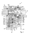
- FIG. 1 shows a partial section of a torque transmission device 1 as a double clutch in the drive train of a motor vehicle, consisting of a - not closer shown - drive unit with a rotatable in a wall 4a of the motor housing mounted crankshaft 4 and a dual-clutch transmission with a about an axis of rotation 2a rotating first transmission input shaft 2 and a second transmission input shaft 3, which is formed in the embodiment shown as a hollow shaft.
- the torque transmission device 1 is in a so-called clutch bell Housed 4b, which forms a closed space with the wall 4a.
- the Torque transmission device 1 is divided into two friction clutches 10, 11th with radially superposed friction units 10a and 11a.
- Every friction clutch 10, 11 is in each case by means of an input part 10b, 11b with the crankshaft 4 and by means of an output member 10c, 11c, each with a transmission input shaft 2, 3 rotationally locked connected.
- the two clutches 10, 11 each friction partners 12a, 12b or 13a, 13b assigned, which in each case one of the corresponding coupling 10, 11th associated disk set consisting of rotationally fixed to the input part 10b, 11b connected friction partners 12a, 12b and rotatably connected to the output part 10c, 11c Friction partners 13a and 13b form.
- the number of friction partners and the arrangement of metallic and non-metallic friction surfaces can meet appropriate requirements following, and it may be particularly advantageous if the total available friction surfaces of both friction clutches 10, 11th be designed so that a practically the same transferable moment about both Couplings results. This can be done, for example, by a different number of Friction partners 12a, 12b and 13a, 13b and / or by correspondingly different radial Ring widths of the friction surfaces take place. However, it can also be used in particular embodiments, For example, in a dual-clutch transmission with a preferred Starting gear on a transmission input shaft 2, 3 be advantageous, this transmission input shaft associated clutch with a correspondingly larger transmission capacity to provide. It is understood that the friction surfaces from the sum of the areas of all Friction partners are formed.
- the coupling of the drive shaft 4 and transmission input shafts 2, 3 takes place by axial pressing of the friction partners 12a, 12b, 13a, 13b by means of one respective clutch 10, 11 associated actuating part 14a, 14b against one on the opposite side of the actuating members 14a, 14b provided Stop 15a, 15b.
- the stops 15a, 15b may be made of a circlip axially fixedly connected to the input or output part or of correspondingly impressed in the input or output part lugs, which may be distributed annularly or over the circumference.
- the actuating parts 14a, 14b are preferably formed on the input parts 10b, 11b of the friction clutches 10, 11 as one-armed levers and technically preferably as components with a force edge and adjoining circumferentially distributed tongues or similar disc parts, wherein the in Figure 2 solid lines the rest position with the clutch 10, 11 and the dashed lines, the operating parts 14a, 14b in the engaged position of the clutch 10, 11 show.
- the actuating parts 14a, 14b act on the friction units 10a, 11a by means of an urging element 14c, 14d, which is respectively arranged between the actuating part 14a, 14b and a friction partner 12a, 12b, so that with increasing actuation, that is, axial displacement of the radial inside of Actuating 14a, 14b at the same time axially fixed tension at the outer end according to an axial lever axial relative displacement is transmitted to the friction units 10a, 11a, so that with increasing distance the friction clutches 10, 11 an increasing torque from the crankshaft 4 to the respectively associated transmission input shaft 2, 3 transmitted.
- the transmission of the torque takes place for example by means of a toothing 2a, 3a between the respective transmission input shaft 2, 3 and the output parts 10c, 11c of the friction clutches 10, 11.
- the output parts can be massively forged, sintered or cast parts, as sheet metal parts or from a Combination of these may be formed, wherein the compounds of these parts may be welded or riveted.
- the actuating members 14a, 14b are preferably disc-shaped and / or stamped disc parts which may be formed to provide an elastic feature of spring steel and / or appropriately positioned at their ends. To increase the wear resistance they can be hardened.
- the operating parts 14a, 14b rotate at the same speed as the input parts of the clutch, so that the actuators 50a, 50b for actuating the operating parts 14a, 14b thereof must therefore be rotationally coupled by means of the actuating bearings 16a, 16b.
- the actuating bearings 16a, 16b would be so-called release bearings, while in the embodiment shown they are to be designated as engagement bearings.
- the actuating devices 50a, 50b are formed in the illustrated embodiment as hydraulic Nehmerritten 51a, 51b, which are displaced axially from the outside, for example by means of a pump unit or by means of a master cylinder, which in turn can be acted upon by an electric motor, by building a pressure and the actuating bearing 16a, 16b and the actuating members 14a, 14b act on the friction clutches.
- per friction clutch 10, 11 a plurality of circumferentially distributed Nehmerikien 51 a, 51 b provided in such a way that they can act on the radially superimposed actuating bearings 16 a, 16 b, although they are arranged to approximately a diameter over the circumference.
- a seal of the chamber 30 to the hydraulic Nehmerritten 51, 51b takes place with respect to the gear 56 on the side of the axial projection 50d of the housing 50c by means of seals, as shown here with reference to FIG. 50f.
- the torque transmission device 1 is provided in such a way that it as Assembly to the rotatably connected to the crankshaft 4 dual-mass flywheel 80 can be mounted.
- the actuators 50a, 50b are fixed to one rotatably received disc-shaped component, so that the housing 50c of the Actuators 50a, 50b rotationally fixed to a wall 56a of the dual clutch transmission can be included.
- the common housing 50c the receiver units 51a, 51b by means of at least one projection 50d in a corresponding AufEnglishung of the transmission or one with the housing 56 of the transmission connected component 56b so connected that by the load moments of the actuating bearing 16a, 16b can support the resulting moment on the housing.
- a bearing 50e for example, a rolling or sliding bearing provided, which supports the operating force within the clutch, so that practically no axial forces are introduced into the transmission housing.
- the friction clutches 10, 11 are preferably wet-running friction clutches, that is, they are intended for operation in the oil bath.
- This can be advantageous be when both couplings have a common input part 17, the is preferably cup-shaped one-sided open, so that a one-sided open Housing 18 for the friction units 10a, 11a formed.
- the common input part 17 can be formed as a sheet metal part and in the region of the axis of rotation 2a, a Have recess in which an axial extension 17a from another, for example hardened material is introduced, which centering the coupling on one of two transmission input shafts 2, 3 (shown here: transmission input shaft 2) takes over.
- a pilot bearing 17b be provided between the transmission input shaft 2 and the axial extension 17a.
- the axial clearance between the torque transmitting device 1 and the crankshaft 4 is set in the first time operating the actuators 50a, 50b, the torque transmission device 1 by pressure build the Nehmerritten 51a, 51b is spaced from the gear housing 56 along the lugs 50d and / or a pressure in the at least partially filled with coolant chamber 30 constructed becomes.
- the dual-mass flywheel 80 is provided and to isolate the wet clutches 10, 11 from each other so that the dual mass flywheel running dry and the friction clutches 10, 11 wet running operated can be.
- a disk part 20, for example a membrane is provided, the opposite to the clutch bell 4b and with respect to the input part 17, for example here at the axial extension 17a, is sealed by a seal 17c.
- the clutch bell 4b For cooling the oil contained in the chamber 30 is within the clutch bell 4b include a pump 270 acting as a gear pump from the input part 17 of the friction clutches 10, 11 is driven.
- a pump 270 acting as a gear pump from the input part 17 of the friction clutches 10, 11 is driven.
- the detailed explanation of the Function of the pump 270 takes place in Figure 4.
- the pump 270 is advantageously with the transmission common swamp located oil in the direction of the friction partner 12a, 12b, 13a, 13b pumped, the capacity of the pump depending can be controlled by the registered friction energy. It goes without saying that at This process also to be supplied lubrication points of the coupling area with Lubricant can be supplied and the pump designed in this way also for Pressure supply of other transmission may be advantageous.
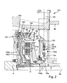
- FIG. 2 shows a torque transmission device 101 with friction clutches which are similar to themselves 10, 11 of the crankshaft 4, a torque on the transmission input shafts 2, 3 can transmit.
- the actuators 150a, 150b are opposite the axis of rotation 2a angularly displaced, so that only the actuator 150b is shown in detail. However, the actuator 150a is substantially provided with the same function.
- the actuator 150a is composed of a Rotary drive 151, which can be arranged outside the clutch bell 4b and a spindle 151a drives.
- the spindle 151a forms a gear with a cam 153 152, wherein the cam fixed to the housing is supported on the gear housing 56 and as a result the rotational movement of the spindle 151a is displaced radially by means of the rotary drive 151.
- the cam 153 acts on the one side rotatably clamped and in the radial direction provided with an axial profile lever 154, so that at a rotation the spindle 151a through the rotary drive 151 an axial displacement of the profiled Lever 154 takes place, which acts on the engagement bearing 114a and thus the actuating part 116a operated, so that a clutch operation as shown in Figure 1.
- the actuators 150a and 150b are described in detail in DE 103 40 528 A1 and explained in more detail.
- the dual mass flywheel 180 is configured in such a way that a first Mass 183 primary side is directly connected to crankshaft 4 and a second mass 182 against the action of the energy storage 181 relative to the first mass is rotatable. In special cases, however, it may be disadvantageous, this twistability to maintain unrestricted. Therefore, between the two masses one Friction device 184 provided, the two masses 182, 183 by the self-adjusting Frictional force connects with each other.
- the mass of the friction elements 187 and the Spring force of the energy storage 186 be tuned so that the release of the friction elements 187 takes place at a desired speed of the crankshaft 4.
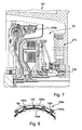
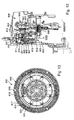
- FIG. 3 shows one of the torque transmission device 1 of FIG. 1 similar to a torque transmission device 201 with a circuit shown schematically a hydraulic device 202 for cooling the friction partners of the friction clutches 10, 11.
- a pump 270 By means of a pump 270.
- the clutch bell 4b integrated pump which may be an internal gear pump 271 ( Figure 4) and that of the torque transmitting device 201, for example by means of the input part 17 of the two friction clutches 10, 11 can be driven is Apply the oil or coolant to the two clutches via an oil cooler 276. It can be advantageous to design the coolant flow so that it is preferably first impinges on the clutch 10, 11, with the predominantly the vehicle is approached.
- the oil is transmitted radially through the friction clutches the friction units 10a, 11a are preferably conveyed along the arrows 202a, 202b and by a differential speed of the crankshaft 4 and the transmission input shafts second compensated for frictional heat generated during a slip phase.
- the coolant flows via the line 203 shown schematically in a non-pressurized Swamp 204 from which it by means of the pump 270 back into the hydraulic Circuit for cooling the clutches 10, 11 is brought.
- volume flow control valve 275 by means of which the volume flow is adapted to the cooling requirement of the clutches 10, 11.
- the volume flow control valve may for example be electrically controlled and controlled in dependence on the speed of one of the shafts 2, 3, 4.
- FIG. 5 shows a corresponding diagram in which the volume flow Q is plotted against the rotational speed N of the crankshaft 4.
- the per se proportional course between the volume flow Q and the rotational speed N at coupled to the input part 17 of the torque transmitting device 201 pump 270 can be limited by the volume flow limiting valve or suction throttle at a predetermined speed limit N limit to a predetermined volume flow Q limit .
- the flow control valve consists of a suction throttle.
- an alternative control of the volume flow limiting valve can take place in such a way that the so-called slip speed is used as the controlled variable, the slip being determined from the rotational speed of each of a transmission input shaft 2, 3 and the crankshaft 4. From this, a volume flow of the pressure medium directly related to the cooling demand of the couplings 10, 11.
- FIG 4 shows an advantageous embodiment of an internal gear pump 271, the in the interior of the chamber 30 directly, so to speak on-site, can be used.
- the internal gear pump 271 has a housing 271a that is stationary, for example on a wall 56a of the gear housing 56 ( Figure 1) is mounted. Radially adjacent to the inner circumference a ring gear 272 is provided, for example, of a rotating component is driven by the approach 20b of Figure 1. With the on the inner circumference of the ring gear 272 arranged internal toothing 272 a meshes with the ring gear 272 with the external teeth 273a of the sun gear 273 for generating the pumping action.
- the suction sickle 274 separates the suction from the pressure side and forms by means of a circular segment 274a a storage or centering for the sun gear 273 on the outer peripheries of the External teeth 273a, so that this is not stored separately.
- Such an arrangement and configuration of a gear pump and its drive is not limited to the use of a coolant flow for cooling a clutch, rather, such an arrangement can also be used for the pressure supply device provided for the actuation of clutches and transmissions, for example of automated manual transmissions, automatic step gears, for adjustment of adjusting cylinders stepless belt transmissions and for actuation dry or wet running friction clutches such as double clutches and Converter lock-up clutches.
- FIG. 6 shows a torque transmission device 301 with a modified one Dual mass flywheel 380 and two friction clutches 10, 11 as a partial section.
- the first and second Masses 382, 383 formed as sheet metal parts and substantially on the input part 380a or axially aligned at the output part 380b that the molded Masses 382, 383 arranged substantially radially over the couplings 10, 11 are.
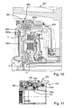
- FIG 7 shows a partial section of a torque transmitting device 401, which in the Modified by the torque transmission device 101 of Figure 2, that instead of the actuators 150a, 150b in the form of lever release Hydraulic release system in the form of the actuators 50a, 50b - as in Figure 1 described in more detail - are used. Is shown in this section only the operation unit 50b. Furthermore, the torque transmission device 401 arranged in the filled with cooling medium chamber 30 pump 270, such as It has already been explained in detail in Figure 1 and in Figures 3-5.
- FIG. 8 shows a detail of an embodiment of a friction device 184a modified from the devices 184 of FIGS. 2 and 584 of FIG. 9 for coupling the two masses of a dual-mass flywheel.
- receptacles for the energy store 186 are provided in the annular projection 185, for example stamped.
- the energy storage 186 apply radially limited, displaceable friction segments 189a, which form a frictional engagement with a merely indicated, located in the cone of the friction segments 189a friction surface 189b (see Figure 7) with bias by means of energy storage 186.
- On the friction segments 189a or on the counter friction surface friction linings may be arranged.
- a further exemplary embodiment can be provided, in particular for smaller coefficients of friction in wet clutches in lamellar construction, in which a frictionally engaged with a first mass member friction plate in both sides frictional contact with components of the other, to be connected via the frictional engagement with the first mass component component (see Figure 9).
- the friction segments 189a-as shown in FIG. 8- are displaced radially outward and come to abutment with the annular projection 185.
- FIG. 9 shows a partial section of a torque transmission device 501 with a in the filled with coolant chamber 530 integrated dual-mass flywheel 580 with the contrary to the effect of the energy storage 581 limited rotatable masses 582, 583.
- a friction device 584 is provided, which is characterized by the previously described friction device 184 of Figure 1 thereby distinguishes that the friction element 589 as a so-called friction plate with two Friction surfaces is formed, each having a frictional contact with the input-side components 589a and 588 form the ring part.
- the friction element 589 is rotationally locked arranged on the output side part of the flywheel 580.
- the energy storage 581 are provided radially outside of the friction clutches 10, 11.
- a scoop tube 503 is further provided, the centrifugal force forced outward coolant scoops and the swamp 204 ( Figure 3) feeds to the hydraulic circuit 202 ( Figure 3) for cooling the Clutches 10, 11 to be available again. Not shown is the drive of Pump by means of the receptacle 580f and the cup-shaped member 580e.
- FIG. 10 shows a comparison with the torque transmission device 501 of FIG. 9 slightly modified embodiment of a torque transmission device 601st in partial section.
- Dual mass flywheel 680 is without friction device for connecting the two Masses 682, 683 configured, wherein the mass 682 is configured in such a way that it is firmly connected to the input part 17 of the couplings 10, 11 and directly with a axially molded approach 682a is acted upon by the energy storage and the transmitted via the crankshaft 4 and the input part 680 c to the energy storage 681 Moment on the input part 17 transmits.
- this output part 680a be formed from the input part 17 by corresponding tabs to be issued.
- Approach 682a and output part 680a can be different Groups of energy storage 681 act and / or the parts 680a, 682a at different angles of rotation of the relative movement relative to the input part 680c counter to the energy storage 681 become effective, so that a two-stage Characteristic of the dual mass flywheel 680 can be provided.
- FIG. 11 shows an advantageous actuating device 750 for the two friction clutches 10, 11 of the previously described torque transmitting devices with a Receiving unit 751, the two ring pistons 752, 753 are assigned, which directly to each other and are arranged radially one above the other.
- the pistons 752, 753 are doing axially displaced by a pressure applied externally to a chamber 752a, 753a, whereby the pistons 752, 753 by means of the actuating bearings 16a, 16b, the actuating parts Act 14a, 14b ( Figure 1) and thus engage the clutch.
- the engagement The couplings 10, 11 takes place against one by elasticity of the operating parts 14a, 14b self-adjusting restoring force, so that when reducing the pressure in the chambers 752a, 753a, the couplings are automatically reopened. It understands itself that the restoring force for closing the clutches elsewhere, For example, in provided for pressure transducer cylinders by appropriate Energy storage materials such as coil springs can be provided.
- the torque transmission device 800 illustrated in FIGS. 12 and 13 comprises a torsional vibration damper 801, one with the output shaft 802 of a motor connectable primary part 803 and a relative to this rotatable abutment 804 has.
- the primary part 803 and secondary part 804 form flywheels, the one have corresponding moment of inertia.
- On the secondary part 804 is interspersed a clutch disc 805 a friction clutch 806 added.
- a torsionally elastic damper 807 provided, which has two series-connected spring groups 808 and 809, the received here in a chamber 811 formed by sheet metal parts 810.
- the chamber 811 may preferably be at least partially filled with a lubricant.
- the two spring groups 808 and 809 are axially one behind the other and practically the same Diameter arranged.
- the primary part 803 has an axial projection 812, on which the secondary part 804 is rotatably mounted, in this case via a plain bearing.
- the series connection of the spring groups 808, 809 takes place in the illustrated Embodiment of disc-shaped components, which corresponding recordings for the springs 808 and 809 and here with the chamber 811 limiting Sheet metal parts 810 are rotatably connected.
- the entrance part of the torsionally elastic damper is formed by a flange-like component 813, which rotatably connected to the primary part 803 is.
- the output part of the torsionally elastic damper 801 is also a flange-like Component 814 is formed, which is non-rotatable with the secondary part 804.
- the sheet-metal parts 810 forming the chamber 811 are as well the loading disks for the springs 808 and 809 connected thereto floating relative to the primary or input part 803 and secondary or output part Arranged 804, that is, rotatable relative to these two parts arranged.
- a friction clutch or friction device 815 is furthermore provided, at low speeds, for example below the idle speed of the engine, also serves as a lock-up clutch.
- the friction clutch 815 has flyweights 816, which are supported by an axial extension 817 of the primary part 803. In which illustrated embodiment, this radial guide pins 818 on the axial Approach 817 provided.
- the centrifugal weights 816, the segment-like over the circumference are formed are, via springs 819, which are biased in the radial direction pushed inward and rely here on friction linings or friction areas 820th at an axial extension 821, which is supported by the secondary part 804 (at least below a certain speed).
- the axial extension 821 is shown in the illustrated Embodiment formed by a cup-shaped sheet metal part 822, which rotatably with the secondary part 804 is.
- the friction clutch 815 is effective in parallel with the torsionally elastic damper 801, so that this according to the design or preload the springs 819 bridged at least from a certain minimum speed can be. This can, among other things, especially when starting the engine existing resonance problem can be solved.
- segment-like Flyweights 816 Due to the relatively large angular design of the segment-like Flyweights 816 have this a brake band-like reinforcing effect. In which illustrated embodiment are considered over the circumference of three such flyweights 816 provided, which in each case extend by 120 degrees in each case.
- the secondary part 804 carries only a simple coupling.
- a double clutch are provided, as for example in connection are described with the remaining figures.
Landscapes
- Engineering & Computer Science (AREA)
- General Engineering & Computer Science (AREA)
- Mechanical Engineering (AREA)
- Physics & Mathematics (AREA)
- Fluid Mechanics (AREA)
- Acoustics & Sound (AREA)
- Aviation & Aerospace Engineering (AREA)
- Hydraulic Clutches, Magnetic Clutches, Fluid Clutches, And Fluid Joints (AREA)
- Structure Of Transmissions (AREA)
- Transmission Devices (AREA)
- Arrangement Of Transmissions (AREA)
Abstract
Die Erfindung betrifft eine Drehmomentübertragungseinrichtung (1) insbesondere für einen Antriebsstrang mit einer Brennkraftmaschine und einem Doppelkupplungsgetriebe (18) mit zwei Getriebeeingangswellen (2,3) und einer Getriebeausgangswelle (4), wobei jede Getriebeeingangswelle mittels einer Kupplung der Drehmomentübertragungseinrichtung mit einer Brennkraftmaschine verbindbar ist. <IMAGE>The invention relates to a torque transmission device (1), in particular for a drive train with an internal combustion engine and a dual-clutch transmission (18) with two transmission input shafts (2, 3) and one transmission output shaft (4), wherein each transmission input shaft can be connected to an internal combustion engine by means of a clutch of the torque transmission device. <IMAGE>
Description
Die Erfindung betrifft eine Drehmomentübertragungseinrichtung insbesondere für einen Antriebsstrang mit einer Brennkraftmaschine und einem Doppelkupplungsgetriebe mit zwei Getriebeingangswellen und einer Getriebeausgangswelle, wobei jede Getriebeeingangswelle mittels einer Kupplung der Drehmomentübertragungseinrichtung mit einer Brennkraftmaschine verbindbar ist.The invention relates to a torque transmission device, in particular for a Powertrain with an internal combustion engine and a dual-clutch transmission with two transmission input shafts and one transmission output shaft, each transmission input shaft by means of a coupling of the torque transmission device with a Internal combustion engine is connectable.
Doppelkupplungsgetriebe mit zwei Getriebeeingangswellen, bei denen Drehmomentübertragungseinrichtungen mit jeweils einer Nasskupplung für jede Getriebeeingangswelle vorgesehen sind, wobei die Nasskupplungen mittels entsprechender Kolbeneinheiten hydrostatisch betätigt werden und der hierfür notwendige Druck sowie gegebenenfalls der Druck zur Kühlung der Kupplungen im Bedarfsfall von einer Druckmittelpumpe generiert wird, sind bekannt. Derartige Pumpen haben hohe Leistungen und verbrauchen entsprechen viel Energie. Zwischen der Pumpe und den Kolbeneinheiten sind zum Aufbau eines von der Pumpe mittels eines Druckmittels erzeugten Drucks zur Betätigung der Kupplungen Drehdurchführungen mit Dichtungen vorgesehen, die zwischen drehenden und stehenden Bauteilen abdichten. Entsprechende Vorkehrungen zur Standzeit dieser Dichtungen müssen getroffen werden.Dual-clutch transmission with two transmission input shafts, where torque-transmitting devices each with a wet clutch for each transmission input shaft are provided, wherein the wet clutches by means of corresponding piston units be hydrostatically actuated and the necessary pressure and optionally the pressure for cooling the couplings in case of need of a pressure medium pump is generated are known. Such pumps have high performance and consume correspond to a lot of energy. Between the pump and the piston units are for Construction of a pressure generated by the pump by means of a pressure medium for actuation The couplings rotary joints provided with seals between the Seal rotating and stationary components. Appropriate arrangements for Service life of these seals must be taken.
Aufgabe der Erfindung ist die Verbesserung einer Drehmomentübertragungseinrichtung und eines Antriebsstrang dahingehend, dass über die Kupplungen der beiden Getriebeeingangswellen bei geringem Energieverbrauch ein hohe Leistung der Brennkraftmaschine übertragen werden kann und gleichzeitig eine einfache und sichere Bedienung der Kupplungen bei hoher Übertragungsleistung und langer Standzeit möglich ist. Außerdem sollen die Herstellungskosten gering und die Fertigung und Montage einfach sein.The object of the invention is the improvement of a torque transmission device and a drive train to the effect that on the clutches of the two transmission input shafts With low energy consumption, high performance of the internal combustion engine can be transmitted and at the same time a simple and safe operation the couplings with high transmission capacity and long life is possible. Furthermore the manufacturing costs are low and the production and assembly easy be.
Die Aufgabe wird durch eine Drehmomentübertragungseinrichtung im Antriebsstrang eines Kraftfahrzeugs zur Übertragung von Drehmoment zwischen einer Brennkraftmaschine mit einer Kurbelwelle und einem Doppelkupplungsgetriebe mit zumindest zwei Getriebeeingangswellen mit zwei Reibungskupplungen unter Verwendung folgender Merkmale gelöst:
- Je eine Getriebeeingangswelle ist mit der Kurbelwelle mittels einer Reibungskupplung koppelbar. Die Anordnung der Getriebeeingangswellen kann konzentrisch mit einer um eine erste Getriebeeingangswelle angeordneten, als Hohlwelle ausgebildeten zweiten Getriebeeingangswelle oder mit parallel zueinander angeordneten Getriebeeingangswellen sein.
- Jede Reibungskupplung verfügt über antriebsseitige und abtriebsseitige Reibeinheiten, die mittels einer axialen Verpressung entlang einer Rotationsachse zumindest einer der Getriebeeingangswellen mit einander zur Bildung eines Reibeingriffs als Reibpartner beaufschlagbar sind. Beispielsweise können von einem Eingangsteil angetriebene und ein Ausgangsteil beaufschlagende Lamellen abwechselnd zu einem Lamellenpaket aufgeschichtet sein, wobei die abtriebsseitigen und/oder die antriebsseitigen Lamellen Reibbeläge zur Erhöhung des Reibwertes der Reibpartner enthalten können.
- Die Reibeinheiten der beiden Reibungskupplungen sind bevorzugt radial übereinander angeordnet, können jedoch bei entsprechend ausgestalteten Bauräumen des Antriebsstrangs axial voneinander beabstandet auf gleichem oder unterschiedlichem Durchmesser angeordnet sein. Um eine gleichmäßige Übertragungsleistung der beiden Reibungskupplungen vorzusehen, können die beiden Reibungskupplungen bezüglich ihrer Reibleistung aufeinander abgestimmt sein, beispielsweise können die ringförmigen Reibpartner der radial äußeren Reibungskupplungen eine kleiner Differenz zwischen Innen- und Außendurchmesser aufweisen und/oder die Reibeinheit der radial äußeren Reibungskupplung kann weniger Reibelemente aufweisen. Die Wahl unterschiedlicher Reibmaterialien kann ebenfalls von Vorteil sein.
- Die Reibeinheiten jeweils einer Reibungskupplung werden mittels eines der jeweiligen Reibeinheit zugeordneten Betätigungsteils entgegen eines Anschlags beaufschlagt. Als Betätigungsteil kann ein Scheiben- oder Hebelteil vorgesehen sein, das mit einem drehenden, axial festen Teil der Kupplung befestigt und gegenüber diesem verschwenkbar sein kann und bei axialer Beaufschlagung die antriebsseitigen und abtriebsseitigen Reibpartner gegen einen Anschlag verpresst, so dass die Reibungskupplung zuerst schlupft und danach haftet. Es kann vorteilhaft sein, die Reibungskupplung nur soweit zu verpressen, das heißt zu schließen, bis das gewünschte Drehmoment von der Brennkraftmaschine auf die entsprechende Getriebeeingangswelle übertragen wird.
- mit dem Betätigungsteil jeder Reibungskupplung ist unter Zwischenschaltung eines Betätigungslagers jeweils eine drehfest mit einem feststehenden Gehäuseteil verbundene, axial auf das jeweilige Betätigungsteil einwirkende Betätigungsvorrichtung angeordnet, beide Reibungskupplungen werden in nasser Betriebsweise betrieben. Auf diese Weise kann ein Betätigungssystem ohne Drehdurchführungen vorgeschlagen werden, da der hydraulische Wirkzusammenhang Druckversorgungseinrichtung / Leitung stehend / Leitung drehend / Druckkolben zur Beaufschlagung der Kupplung - wie aus Doppelkupplungen des Stands der Technik - mittels eines mechanischen Betätigungslagers zur Drehentkopplung von Betätigungsvorrichtung und Kupplung umgangen werden kann. Auf diese Weise steht auch ein Drehmomentübertragungssystem zur Verfügung, dessen Reibungskupplungen unabhängig von der Betätigung des Doppelkupplungsgetriebes ― hydraulisch, pneumatisch, mittels elektrischer Aktorik oder deren Kombinationen - mit dem geeigneten Betätigungssystem ausgestattet werden kann.
- Depending on a transmission input shaft can be coupled to the crankshaft by means of a friction clutch. The arrangement of the transmission input shafts may be concentric with a second transmission input shaft arranged around a first transmission input shaft, designed as a hollow shaft, or with transmission input shafts arranged parallel to one another.
- Each friction clutch has drive-side and output-side friction units, which can be acted upon by means of an axial compression along an axis of rotation of at least one of the transmission input shafts with each other to form a frictional engagement as a friction partner. For example, louvers driven by an input part and acting on an output part can be stacked alternately to form a lamella packet, wherein the output-side and / or the drive-side lamellae can contain friction linings for increasing the coefficient of friction of the friction partners.
- The friction units of the two friction clutches are preferably arranged radially one above the other, but may be arranged axially spaced from each other at the same or different diameter with correspondingly designed installation spaces of the drive train. In order to provide a uniform transmission power of the two friction clutches, the two friction clutches can be matched with respect to their friction, for example, the annular friction partners of the radially outer friction clutches may have a small difference between inner and outer diameter and / or the friction unit of the radially outer friction clutch may have fewer friction elements exhibit. The choice of different friction materials may also be beneficial.
- The friction units of a respective friction clutch are acted upon by means of one of the respective friction unit associated actuating part against a stop. As an actuating part, a disc or lever member may be provided, which may be attached to a rotating, axially fixed part of the coupling and pivotable relative to this and the axial pressure on the drive side and driven side friction partners pressed against a stop, so that the friction clutch first slips and then liable. It may be advantageous to compress the friction clutch only to the extent that is close, until the desired torque is transmitted from the engine to the corresponding transmission input shaft.
- with the operating part of each friction clutch is connected to an actuating bearing in each case a rotatably connected to a fixed housing part, axially acting on the respective actuating member actuator disposed, both friction clutches are operated in wet mode. In this way, an actuating system without rotary feedthroughs can be proposed, since the hydraulic effect connection pressure supply / line standing / line rotating / pressure piston for acting on the clutch - as from dual clutches of the prior art - can be bypassed by means of a mechanical actuator bearing for rotational decoupling of actuator and clutch , In this way, a torque transmission system is available whose friction clutches can be equipped with the appropriate actuating system independently of the operation of the dual-clutch transmission - hydraulic, pneumatic, by means of electrical actuators or their combinations.
Es kann daher eine Drehmomentübertragungseinrichtung mit einer Betätigungsvorrichtung vorteilhaft sein, die elektrohydraulisch ist. Dabei kann zumindest eine Betätigungsvorrichtung aus einer mittels eines Elektromotors betätigbaren hydraulischen Gebereinheit, bestehend aus einer Kolben-/Zylindereinheit, zumindest einer das entsprechende Betätigungslager axial beaufschlagenden hydraulischen Nehmereinheit , bestehend aus einer Kolben-/Zylindereinheit, und einer Gebereinheit und Nehmereinheit verbindenden Druckmittelleitung gebildet sein. Die Nehmereinheit kann mehrere, über den Umfang verteilte, um zumindest eine Getriebeeingangswelle angeordnete Untereinheiten zur Beaufschlagung eines Betätigungslagers aufweisen, wobei zur Beaufschlagung beider Reibungskupplungen beide Nehmereinheiten über den Umfang verteilte Untereinheiten aufweisen und diese über den Umfang abwechselnd verteilt und auf annähernd gleichem Umfang angeordnet sein können. Alternativ kann eine Nehmereinheit für eine Reibungskupplung aus einem druckbeaufschlagbaren Ringzylinder mit darin axial verlagerbarem Ringkolben sein, wobei zwei radial übereinander angeordneten Nehmereinheiten jeweils eine Reibungskupplung betätigen können. Besonders vorteilhaft kann eine Anordnung sein, bei der ein äußerer Ringkolben direkt axial verlagerbar auf einem radial inneren Ringkolben dichtend gelagert ist, wobei für beide Kolben ein separater Druckraum vorgesehen ist, so dass beide Kupplungen unabhängig voneinander betätigbar sind.It can therefore be a torque transmission device with an actuator be advantageous, which is electro-hydraulic. In this case, at least one actuating device from an actuatable by means of an electric motor hydraulic transmitter unit, consisting of a piston / cylinder unit, at least one of the corresponding Actuating bearing axially acting hydraulic slave unit, consisting of a piston / cylinder unit, and a transmitter unit and receiver unit connecting Be formed pressure medium line. The receiving unit can be several, over the circumference distributed to at least one transmission input shaft disposed subunits for applying having an actuating bearing, wherein for applying both friction clutches both subunits distributed circumferentially subunits and these distributed over the circumference alternately and on approximately the same Scope can be arranged. Alternatively, a slave unit for a friction clutch from a pressurizable ring cylinder with axially displaceable therein Be annular piston, wherein two radially superposed Nehmereinheiten can each operate a friction clutch. Particularly advantageous may be an arrangement be, in which an outer annular piston directly axially displaceable on a radial inner annular piston is sealingly mounted, with a separate pressure chamber for both pistons is provided so that both clutches independently operable are.
Insbesondere für Antriebsstränge mit einem hydraulisch betätigten Doppelkupplungsgetriebe mit einer Pumpe und einem Steuerteil zum Steuern der hydraulischen Bauelemente der Schaltung kann es vorteilhaft sein, Nehmereinheiten zur Beaufschlagen der Betätigungslager direkt in einer Wandung des Getriebegehäuses aufzunehmen, wobei diese von dem Steuerteil gesteuert mit Druck der Pumpe versorgt werden und die Kupplungen betätigen. Es kann vorteilhaft sein, eine derartige Anordnung auf für Einfachkupplung in Verbindung mit einem hydraulisch gesteuerten Automatikgetriebe wie einem automatisierten Schaltgetriebe (ASG) oder einem stufenlosen Automatikgetriebe (CVT) zu verwenden. Dabei kann eine Kolben-/Zylindereinheit in der Wandung des Getriebes und/oder im entsprechenden Steuerteil aufgenommen sein oder zumindest ein Kolben kann in einem in der Gehäusewandung oder dem Steuerteil eingearbeiteten Zylinder axial verlagerbar eingebracht sein.In particular for drive trains with a hydraulically actuated dual-clutch transmission with a pump and a control part for controlling the hydraulic components It may be advantageous for the circuit to have slave units for acting on the actuating bearings directly in a wall of the gear housing, this being controlled by the control part to be supplied with pressure of the pump and the clutches actuate. It may be advantageous to have such an arrangement for single clutch in Connection with a hydraulically controlled automatic transmission such as an automated Manual transmission (ASG) or a continuously variable transmission (CVT) to use. In this case, a piston / cylinder unit in the wall of the transmission and / or be received in the corresponding control part or at least one piston can axially in a machined in the housing or the control part cylinder be displaced introduced.
Ein weiteres Ausgestaltungsbeispiel kann eine elektromechanische Betätigungsvorrichtung
vorsehen, wobei die Beaufschlagung zumindest einer Reibungskupplung mittels eines
im wesentlichen senkrecht zu einer der Getriebeeingangswellen angeordneten elektromotorischen
Drehantriebes erfolgt, wobei die rotatorische Bewegung mittels eines
Getriebes in eine translatorische Bewegung entlang einer der Getriebeeingangswellen
zur Beaufschlagung des entsprechenden Betätigungslagers gewandelt wird. Hierzu sei
beispielsweise die deutsche Patentanmeldung mit dem Aktenzeichen 103 40 528.3 genannt,
deren Inhalt vollständig in die vorliegende Anmeldung aufgenommen ist. Alternativ
hierzu kann die Beaufschlagung zumindest einer Reibungskupplung mittels eines im
wesentlichen parallel oder konzentrisch zu einer der Getriebeeingangswelle angeordneten
elektromotorischen Drehantriebes erfolgen, wobei die rotatorische Bewegung mittels
eines Getriebes in eine translatorische entlang dieser Getriebeeingangswelle zur Beaufschlagung
des entsprechenden Betätigungslagers gewandelt wird. Hierzu sei beispielsweise
die deutsche Patentoffenlegung DE 100 33 649 A1 genannt.Another embodiment may be an electromechanical actuator
provide, wherein the application of at least one friction clutch by means of a
substantially perpendicular to one of the transmission input shafts arranged electromotive
Rotary drive takes place, wherein the rotational movement by means of a
Gear in a translational movement along one of the transmission input shafts
is converted to act on the corresponding actuating bearing. To do this
For example, the German patent application with the file number 103 40 528.3 mentioned,
the contents of which are fully incorporated in the present application. alternative
For this purpose, the application of at least one friction clutch by means of an im
substantially parallel or concentric with one of the transmission input shaft
electromotive rotary drive, wherein the rotational movement means
a transmission in a translational along this transmission input shaft for applying
the corresponding actuating bearing is converted. For this purpose, for example
the German
Es versteht sich, dass die beiden im Nassbetrieb betriebenen Reibungskupplungen in speziellen Einsätzen zwangsweise geschlossene Kupplungen sein können die unter Anwendung einer Axialkraft ausgerückt werden. In Standardeinsätzen sind diese Reibungskupplungen jedoch zugedrückte Kupplungen, das heißt, sie sind im nicht von der Betätigungsvorrichtung beaufschlagten Zustand ausgerückt und werden durch Beaufschlagen mit einer Axialkraft eingerückt.It is understood that the two operated in wet operation friction clutches in special uses forcibly closed couplings can be under Application of an axial force are disengaged. In standard applications these are friction clutches However, pressed couplings, that is, they are not in the Actuator acted upon state disengaged and are by applying engaged with an axial force.
Besonders vorteilhaft ist die Betätigung der nass betriebenen Kupplungen mit einer von der Drehrehzahl der Brennkraftmaschine unabhängigen Betätigungseinrichtung der vorgeschlagenen Ausführungen in Verbindung mit einer so genannten Start-Stopp-Einrichtung, bei der während eines Stands des Fahrzeugs oder bei Bergabfahrten die Brennkraftmaschine stillgelegt wird und bei einer Lastanforderung, beispielsweise durch das Gaspedal, die Brennkraftmaschine gestartet wird und mit zumindest einer Kupplung angefahren beziehungsweise die Fahrt fortgesetzt werden soll. Während bei mittels einer Pumpe betätigten Kupplungen diese vom vollständig ausgerückten Zustand nach dem Starten der Brennkraftmaschine und dem nachfolgenden Druckaufbau durch die Pumpe von dieser Stellung wieder zum Greifpunkt bewegt werden müssen und dann erst Reibmoment auf das Getriebe übertragen werden kann, erfolgt ein derartiger Vorgang bei den erfindungsgemäßen Betätigungseinrichtungen schneller, da mittels unabhängig vom Betriebszustand der Brennkraftmaschine zumindest eine Kupplung am Greifpunkt gehalten werden kann und nach Starten der Brennkraftmaschine unverzüglich ein über diese Kupplung auf das Getriebe übertragbares Moment zur Verfügung steht.Particularly advantageous is the operation of the wet-operated clutches with one of the Drehrehzahl the internal combustion engine independent actuator of the proposed Embodiments in connection with a so-called start-stop device, during a stand of the vehicle or on downhill the Internal combustion engine is shut down and at a load request, for example by the accelerator pedal, the internal combustion engine is started and with at least one clutch approached or the journey is to be continued. While in by means of a Pump operated clutches this from the fully disengaged state the starting of the internal combustion engine and the subsequent pressure build-up by the Pump must be moved from this position back to the gripping point and then only friction torque can be transmitted to the transmission, such a process takes place in the actuation devices according to the invention faster because by means of independent from the operating state of the internal combustion engine at least one clutch on Grab point can be kept and after starting the engine immediately a transmissible via this clutch to the transmission torque available stands.
Zur Kühlung zumindest einer der Reibungskupplungen, insbesondere wenn eine große
Reibungswärme infolge Schlupf entsteht, kann es vorteilhaft sein, einen Kühlmittelstrom
zur Kühlung zumindest einer Reibungskupplung mittels einer Pumpe bereit zu stellen.
Zu einer weitgehend vom Getriebe unabhängigen Betriebsweise kann diese Pumpe im
Bereich einer zwischen einer Wandung der Brennkraftmaschine und einer Wandung des
Doppelkupplungsgetriebes gebildeten Kupplungsglocke angeordnet sein. Dabei kann ein
Kühlmittelstrom aus einem mit dem Getriebe gemeinsamen Ölsumpf oder aus dem Getriebe
selbst mittels der Pumpe angesaugt oder ein für die Reibungskupplungen getrennter
Ölkreislauf vorgesehen sein. Es kann weiterhin vorteilhaft sein, die Pumpe insbesondere
wenn keine hydraulische Pumpe zur Steuerung des Getriebes vorhanden ist, in ihrer
Leistung so auszulegen, dass die Bereitstellung des Kühlmittelstroms möglich ist. Die
Pumpe kann von der Kurbelwelle oder einem mit dieser verbundenen Bauteil angetrieben
sein. Beispielsweise kann bei einer Anordnung der Pumpe an dem Getriebegehäuse
ein Kupplungsbauteil in der Nähe des Getriebes mit der Pumpe verzahnt werden. In
vorteilhafter Weise handelt es sich dabei um ein mit dem Lamellenträger verbundenes
Bauteil, das mittels eines Zahnrads das Hohlrad einer radial weiter außen angeordneten
Innenzahnradpumpe antreibt, wobei die Innenzahnradpumpe vorteilhafterweise in einem
Bauraum sparenden Bereich, beispielsweise zwischen zwei Getriebeaugen des Getriebes
angeordnet ist. Dabei kann die Pumpe an einer Gehäusewandung des Getriebes
angeordnet sein und zwar abhängig vom jeweiligen Getriebekonzept im Bauraum der
Kupplungsglocke oder im Bauraum des Getriebes. Auch eine Integration in die Gehäusewand
oder bei einem gemeinsamen Bauraum mit dem Getriebe in einer entsprechenden
Halterung des gemeinsamen Bauraums kann vorteilhaft sein.
Es versteht sich, dass die Pumpe auch elektrisch angetrieben sein kann. Der Antrieb
durch die Kurbelwelle oder einen Elektromotor kann mittels einer Zahnradverbindung,
einem Riemenantrieb, eines Kettenantriebs oder dergleichen erfolgen.For cooling at least one of the friction clutches, in particular when a large frictional heat arises as a result of slip, it may be advantageous to provide a coolant flow for cooling at least one friction clutch by means of a pump. For a largely independent of the transmission mode of operation, this pump may be arranged in the region of a clutch bell formed between a wall of the internal combustion engine and a wall of the dual clutch transmission. In this case, a coolant flow can be drawn in from an oil sump common to the transmission or from the transmission itself by means of the pump, or a separate oil circuit can be provided for the friction clutches. It may also be advantageous to design the pump in terms of its performance, in particular if no hydraulic pump is provided for controlling the transmission, in such a way that provision of the coolant flow is possible. The pump may be driven by the crankshaft or a component connected thereto. For example, in an arrangement of the pump to the transmission housing, a coupling member in the vicinity of the transmission to be meshed with the pump. This is advantageously a component connected to the plate carrier which drives the ring gear of a radially further outwardly arranged internal gear pump by means of a gear wheel, wherein the internal gear pump is advantageously arranged in a space-saving area, for example between two gear wheels of the gearbox. In this case, the pump may be arranged on a housing wall of the transmission and indeed depending on the particular transmission concept in the space of the clutch bell or in the space of the transmission. An integration in the housing wall or in a common space with the transmission in a corresponding holder of the common space may be advantageous.
It is understood that the pump can also be electrically powered. The drive by the crankshaft or an electric motor can be done by means of a gear connection, a belt drive, a chain drive or the like.
Die Innenzahnradpumpe kann mittels eines Hohlrads mit einer Innenverzahnung angetrieben
sein, wobei diese Innenverzahnung mit einer Außenverzahnung eines Sonnenrads
kämmt und wobei zum Ansaugen des Kühlmittels eine Saugsichel vorgesehen ist.
In vorteilhafter Weise kann das Sonnenrad mittels seiner Außenverzahnung an einem zu
diesem komplementären Segment der Saugsichel radial gelagert sein, so dass eine separate
Lagerung des Sonnenrads entfallen kann. Wahlweise kann auch die Verwendung
einer Gerotorpumpe vorteilhaft sein. Zur Minimierung des Energiebedarfs der Pumpe
kann deren Volumenstrom mittels einer Saugdrosselung geregelt werden, wobei die
Saugdrosselung mittels eines Elektromagnetventils erfolgen kann. Auf diese Weise kann
ein Volumenstrom beispielsweise bis zu einer vorgegebenen Drehzahl der Antriebsdrehzahl
proportional sein und ab einer Grenzdrehzahl auf einem konstanten Wert gehalten
werden. Erfahrungswerte haben gezeigt, dass eine Begrenzung des Kühlmitteldrucks
auf 5 bar, vorzugsweise 3 bar und ein Volumenstrom von maximal 36 l/min, vorzugsweise
24 l/min vorteilhaft sein kann. In vorteilhafter Weise kann ein zwischen Pumpe und
den Reibeinheiten der Reibungskupplungen ein Ölkühler geschaltet sein. Das Kühlmittel
kann durch eine entsprechende Öffnung in der Kammer in den Sumpf entweichen, wobei
es vorteilhaft sein kann, infolge Fliehkrafteinflusses nach radial außen gedrängtes
Kühlmittel mit einem gehäusefest angebrachten Schöpfrohr aufzufangen und in den
Sumpf zu leiten. Ein derartiges Schöpfrohr kann vorteilhafterweise zu einer Baueinheit
mit anderen Funktionselementen, beispielsweise einer Nehmereinheit kombiniert werden.
Es versteht sich, dass für spezielle Anwendungen auch andere Pumpen wie Radialkolbenpumpen,
Flügelzellenpumpen, Membranpumpen und dergleichen vorteilhaft sein
können.The internal gear pump can be driven by means of a ring gear with an internal toothing, said internal toothing meshes with an external toothing of a sun gear and wherein for suction of the coolant, a suction cup is provided. Advantageously, the sun gear can be supported radially by means of its external toothing on a complementary segment of the suction cup, so that a separate storage of the sun gear can be omitted. Optionally, the use of a gerotor pump may be advantageous. To minimize the energy requirement of the pump whose volume flow can be regulated by means of a suction throttling, wherein the suction throttling can be effected by means of a solenoid valve. In this way, a volume flow, for example, be proportional to the drive speed up to a predetermined speed and kept at a constant value from a limit speed. Experience has shown that a limitation of the coolant pressure to 5 bar, preferably 3 bar and a flow rate of not more than 36 l / min, preferably 24 l / min may be advantageous. In an advantageous manner, an oil cooler can be connected between the pump and the friction units of the friction clutches. The coolant can escape through a corresponding opening in the chamber in the sump, and it may be advantageous to catch due to centrifugal force radially outwardly crowded coolant with a scoop mounted fixed to the housing and to lead into the sump. Such a scoop can be advantageously combined to form a unit with other functional elements, such as a slave unit.
It is understood that for special applications, other pumps such as radial piston pumps, vane pumps, diaphragm pumps and the like may be advantageous.
Nach dem erfinderischen Gedanken kann die gesamte Kupplungsglocke mit Kühl- bzw. Druckmittel, beispielsweise handelsübliches ATF, gefüllt sein, auch kann ein mit dem Getriebe gemeinsamer Bauraum vorgesehen sein. Besonders vorteilhaft ist es jedoch, wenn in der Kupplungsglocke zwischen einer Wandung der Brennkraftmaschine und einer Wandung des Doppelkupplungsgetriebes eine separate, gegen die Kupplungsglocke flüssigkeitsdicht abgedichtete Kammer gebildet ist, in der zumindest die beiden Reibungskupplungen aufgenommen sind. Diese Kammer kann von einem beide Reibungskupplungen umgreifenden Bauteil, beispielsweise einem topfförmigen Eingangsteil wie Lamellenträger, gebildet werden, wobei ein mit diesem verbundenes Teil auf einem feststehenden Teil wie beispielsweise einem Bauteil der Betätigungsvorrichtung oder des Getriebegehäuses dichtend und drehbar gelagert sein kann. Alternativ hierzu kann zur Bildung der Kammer ein Scheibenteil mit dem Getriebegehäuse fest verbunden sein und verdrehbar und flüssigkeitsdicht auf einem drehenden Teil, wie beispielsweise auf der Nabe des Eingangsteils sein.According to the inventive idea, the entire clutch bell with cooling or Pressure medium, such as commercial ATF, be filled, also can be with the Gear common space can be provided. However, it is particularly advantageous if in the clutch bell between a wall of the internal combustion engine and a Wall of the dual clutch transmission a separate, against the clutch bell liquid-tight sealed chamber is formed, in which at least the two friction clutches are included. This chamber can by one of both friction clutches encompassing component, such as a cup-shaped input part such as Lamellenträger, be formed, with a part connected to this on a fixed Part such as a component of the actuator or the Transmission housing can be mounted sealingly and rotatably. Alternatively, for Forming the chamber a disk part to be firmly connected to the transmission housing and rotatable and liquid-tight on a rotating part, such as on the Be the hub of the entrance section.
Die erfindungsgemäße Anordnung der beiden Reibungskupplungen kann als Baueinheit ausgestaltet sein, die direkt auf der Kurbelwelle aufgenommen ist. Dabei kann das Betätigungssystem ebenfalls direkt an dieser Einheit angeordnet sein und beim Zusammenbau mit dem Getriebe drehfest zur Ausbildung einer Drehmomentstütze verbunden werden, wobei die einzelnen Kupplungsaggregate mit dem Betätigungssystem verdrehbar verbunden und gelagert sind. In weiteren Ausgestaltungsbeispielen kann das Kupplungsaggregat auf der Kurbelwelle aufgenommen und abgestützt sein, während die Betätigungseinrichtung an Getriebegehäuse vormontiert ist. Mit der Betätigungseinrichtung kann gleichzeitig die Kühlmittelpumpe vormontiert werden. Eine Axial- und/oder Radiallagerung dieser kann am Getriebegehäuse vorgesehen sein.The inventive arrangement of the two friction clutches can as a unit configured, which is recorded directly on the crankshaft. In this case, the actuation system also be placed directly on this unit and during assembly be rotatably connected to the transmission to form a torque arm, wherein the individual clutch units rotatable with the actuating system connected and stored. In further embodiments, the clutch unit be received and supported on the crankshaft while the actuator is pre-assembled to gear housing. With the actuating device the coolant pump can be pre-assembled at the same time. An axial and / or radial bearing this can be provided on the gear housing.
Zur Verminderung oder Eliminierung von von der Brennkraftmaschine in das Getriebe eingetragenen Drehschwingungen kann an der Drehmomentübertragungseinrichtung ein zwischen Kurbelwelle und Eingangsteil der beiden Reibungskupplungen angeordnetes Zweimassenschwungrad vorgesehen werden. Dieses Zweimassenschwungrad kann in die mit Druckflüssigkeit befüllte Kammer integriert sein oder außerhalb der Kammer angeordnet sein. Das Zweimassenschwungrad kann weiterhin einen Teil des Gehäuses für die Kammer bilden und/oder ein Antriebsteil für die Pumpe aufweisen. Die Aufnahme des Zweimassenschwungrads auf der Kurbelwelle kann mittels eines axial flexiblen Scheibenteils, einer so genannten "flexplate" erfolgen. Es versteht sich, dass die Drehmomentübertragungseinrichtung ohne Zweimassenschwungrad ebenfalls in dieser Weise auf der Kurbelwelle aufgenommen sein kann. Besonders vorteilhaft in Verbindung mit den Massenverhältnissen einer Doppelkupplung kann es sein, zwei entgegen zumindest eines in Umfangsrichtung wirksamen Energiespeichers relativ verdrehbaren, bezogen auf das Schwungrad antriebsseitige und abtriebsseitige Massen zumindest vorübergehend miteinander koppelbar zu gestalten, wobei die die Kopplung mittels einer fliehkraftabhängigen Reibeinrichtung erfolgen kann. Besonders vorteilhaft kann die Verwendung einer Koppelung bei Massenverhältnissen sein, bei denen das antriebsseitige Trägheitsmoment größer als das abtriebsseitige ist, beispielsweise weist eine erste, antriebsseitig koppelbare Masse ein Trägheitsmoment von 0,1 ± 0,04 kgm2 und eine zweite, abtriebsseitige Masse weist ein Trägheitsmoment von 0,04 + 0,04 kgm2 auf. Es hat sich weiterhin als vorteilhaft erweisen, die Kopplung der beiden Massen bis zu einem Bereich von 1200 bis 1800 Umdrehungen pro Minute aufrecht zu erhalten. In order to reduce or eliminate torsional vibrations introduced by the internal combustion engine into the transmission, a two-mass flywheel arranged between crankshaft and input part of the two friction clutches can be provided on the torque transmission device. This dual mass flywheel may be integrated into the pressurized liquid filled chamber or disposed outside the chamber. The dual mass flywheel may further form part of the housing for the chamber and / or have a drive part for the pump. The inclusion of the dual mass flywheel on the crankshaft can be done by means of an axially flexible disc part, a so-called "flexplate". It is understood that the torque transfer device without dual mass flywheel can also be accommodated in this way on the crankshaft. Particularly advantageous in connection with the mass ratios of a dual clutch, it may be at least temporarily to make mutually opposite at least one circumferentially effective energy storage relatively rotatable, based on the flywheel drive side and output side masses, wherein the coupling can be done by means of a centrifugal force-dependent friction device. Particularly advantageous may be the use of a coupling in mass ratios in which the drive-side moment of inertia is greater than the output side, for example, has a first, drive side coupled mass an inertia of 0.1 ± 0.04 kgm 2 and a second, output side mass has Moment of inertia of 0.04 + 0.04 kgm 2 on. It has also proved to be advantageous to maintain the coupling of the two masses up to a range of 1200 to 1800 revolutions per minute.
Die Montage der Drehmomentübertragungseinrichtung kann in der Weise vorgesehen sein, dass die komplette Baueinheit mit Nehmereinheit und gegebenenfalls mit Zweimassenschwungrad auf einer oder beiden Getriebeeingangswellen des Doppelkupplungsgetriebes aufgenommen und beim Zusammenfügen von Brennkraftmaschine und Getriebe an einem axial flexiblen, mit der Kurbelwelle verbundenen Antriebsbauteil wie "flexplate" drehfest verbunden wird. Es kann auch vorteilhaft sein, Teile des Zweimassenschwungrads oder das gesamte Zweimassenschwungrad getrennt von der Kupplungseinheit mit der Kurbelwelle zu verbinden und über Verbindungselemente wie Steckverbindungen, die eine axiale Verlagerbarkeit und eine drehfeste Mitnahme der verbundene Teile erlauben, eine Verbindung von Brennkraftmaschine und Getriebe zu schaffen. Zu Führungszwecken der Drehmomentübertragungseinrichtung kann an dieser ein Pilotlager vorgesehen sein, mittels dessen die Drehmomentübertragungseinrichtung auf der Kurbelwelle verdrehbar aufgenommen ist. Eine axiale Abstützung der Drehmomentübertragungseinrichtung an der Kurbelwelle, beispielsweise mittels eines Gleitlagers kann ebenfalls von Vorteil sein. Von besonderem Vorteil kann sein, die Drehmomentübertragungseinrichtung beziehungsweise deren axial verlagerbaren Bauteile bei der Montage axial lediglich grob zu justieren, die Betätigungsvorrichtung drehfest, jedoch axial verlagerbar mit dem Getriebegehäuse zu verbinden und bei erstmaligem Betrieb der Drehmomentübertragungseinrichtung durch einen sich einstellenden axial wirksamen Druck des Kühlmittels auf die axial verlagerbaren Bauteile endgültig zu positionieren, beispielsweise indem diese auf entsprechend angeordnete Anschläge auflaufen.The mounting of the torque transmitting device may be provided in this way be that the complete unit with slave unit and optionally with dual mass flywheel on one or both transmission input shafts of the dual-clutch transmission taken and the joining of internal combustion engine and Transmission on an axially flexible, connected to the crankshaft drive component such as "Flexplate" rotatably connected. It may also be advantageous to use parts of the dual mass flywheel or the entire dual mass flywheel separated from the coupling unit to connect with the crankshaft and via fasteners like Plug-in connections, the axial displacement and a rotationally fixed entrainment of connected parts allow a connection of the engine and transmission to create. For guiding purposes of the torque transmitting device can at this a pilot bearing be provided, by means of which the torque transmission device is recorded rotatably on the crankshaft. An axial support of Torque transmission device on the crankshaft, for example by means of a Slide bearing can also be beneficial. Of particular advantage may be the Torque transmission device or its axially displaceable components axially only roughly adjust during assembly, the actuator rotatably, However, axially displaceable to connect to the transmission housing and at first Operation of the torque transmitting device by adjusting itself axially effective pressure of the coolant to the axially displaceable components finally position, for example, by accumulating on appropriately arranged attacks.
Die Erfindung wird anhand der Figuren näher erläutert. Dabei zeigen:
Figur 1- einen Teilschnitt einer Drehmomentübertragungseinrichtung,
Figur 2- einen Teilschnitt einer Drehmomentübertragungseinrichtung,
Figur 3- einen Teilschnitt mit schematisch dargestellter Anbindung an einen Kühlkreislauf,
Figur 4- einen Schnitt durch eine Pumpe,
- Figur 5
- ein Diagramm zur Darstellung des Volumenstroms in Abhängigkeit von einer Antriebsdrehzahl der Pumpe,
- Figur 6
- einen Teilschnitt einer Drehmomentübertragungseinrichtung,
- Figur 7
- einen Teilschnitt einer Drehmomentübertragungseinrichtung,
- Figur 8
- ein Detail zum Ausführungsbeispiel der Figur 7,
- Figur 9
- ein Teilschnitt einer Drehmomentübertragungseinrichtung und
Figur 10- einen Teilschnitt einer Drehmomentübertragungseinrichtung.
Figur 11- zeigt eine Betätigungseinrichtung für eine Reibungskupplung,
- Figuren 12 und 13
- eine besonders vorteilhafte Ausgestaltung einer Drehmomentübertragungseinrichtung mit einer Dämpfungseinrichtung, die sowohl in Zusammenhang mit Einfachkupplungen als auch mit Doppelkupplungen Verwendung finden kann.
- FIG. 1
- a partial section of a torque transmission device,
- FIG. 2
- a partial section of a torque transmission device,
- FIG. 3
- a partial section with schematically illustrated connection to a cooling circuit,
- FIG. 4
- a section through a pump,
- FIG. 5
- a diagram for the representation of the volume flow as a function of a drive speed of the pump,
- FIG. 6
- a partial section of a torque transmission device,
- FIG. 7
- a partial section of a torque transmission device,
- FIG. 8
- a detail of the embodiment of Figure 7,
- FIG. 9
- a partial section of a torque transmission device and
- FIG. 10
- a partial section of a torque transmitting device.
- FIG. 11
- shows an actuating device for a friction clutch,
- FIGS. 12 and 13
- a particularly advantageous embodiment of a torque transmission device with a damping device that can be used both in connection with single clutches and with dual clutches use.
Figur 1 zeigt einen Teilschnitt einer Drehmomentübertragungseinrichtung 1 als Doppelkupplung
im Antriebsstrang eines Kraftfahrzeuges, bestehend aus einer ― nicht näher
gezeigten - Antriebseinheit mit einer in einer Wandung 4a des Motorgehäuses verdrehbar
gelagerten Kurbelwelle 4 und einem Doppelkupplungsgetriebe mit einer um eine Rotationsachse
2a rotierenden ersten Getriebeeingangswelle 2 sowie einer zweiten Getriebeeingangswelle
3, die im gezeigten Ausführungsbeispiel als Hohlwelle ausgebildet ist.
Die Drehmomentübertragungseinrichtung 1 ist in einer so genannten Kupplungsglocke
4b untergebracht, die mit der Wandung 4a einen geschlossenen Bauraum bildet. Die
Drehmomentübertragungseinrichtung 1 gliedert sich in zwei Reibungskupplungen 10, 11
mit radial übereinander angeordneten Reibeinheiten 10a und 11a. Jede Reibungskupplung
10, 11 ist jeweils mittels eines Eingangsteils 10b, 11b mit der Kurbelwelle 4 und mittels
eines Ausgangsteils 10c, 11c mit jeweils einer Getriebeeingangswelle 2, 3 drehschlüssig
verbunden. Im Kraftfluss zwischen den Eingangsteilen 10b, 11b und den Ausgangsteilen
10c, 11c sind den beiden Kupplungen 10, 11 jeweils Reibpartner 12a, 12b
bzw. 13a, 13b zugeordnet, wobei diese jeweils ein der entsprechenden Kupplung 10, 11
zugeordnetes Lamellenpaket bestehend aus drehfest mit dem Eingangsteil 10b, 11b
verbundenen Reibpartnern 12a, 12b und drehfest mit dem Ausgangsteil 10c, 11c verbundenen
Reibpartnern 13a und 13b bilden. Die Anzahl der Reibpartner sowie die Anordnung
von metallischen und nichtmetallischen Reibflächen kann entsprechenden Anforderungen
folgend ausgelegt werden, wobei es besonders vorteilhaft sein kann, wenn
die insgesamt zur Verfügung stehenden Reibflächen beider Reibungskupplungen 10, 11
so ausgelegt werden, dass ein praktisch gleiches übertragbaren Moments über beide
Kupplungen resultiert. Dies kann beispielsweise durch eine unterschiedliche Anzahl von
Reibpartnern 12a, 12b und 13a, 13b und/oder durch entsprechend unterschiedliche radiale
Ringbreiten der Reibflächen erfolgen. Es kann jedoch auch in besonderen Ausführungsformen,
beispielsweise bei einem Doppelkupplungsgetriebe mit einem bevorzugten
Anfahrgang auf einer Getriebeeingangswelle 2, 3 vorteilhaft sein, die dieser Getriebeeingangswelle
zugeordnete Kupplung mit einer entsprechend größeren Übertragungskapazität
zu versehen. Es versteht sich, dass die Reibflächen aus der Summe der Flächen aller
Reibpartner gebildet werden.FIG. 1 shows a partial section of a
Die Kopplung von Antriebswelle 4 und Getriebeeingangswellen 2, 3 erfolgt durch axiales
Verpressen der Reibpartner 12a, 12b, 13a, 13b mittels jeweils einem einer Kupplung 10,
11 zugeordneten Betätigungsteil 14a, 14b gegen jeweils einen auf der gegenüber liegenden
Seite der Betätigungsteile 14a, 14b vorgesehenen Anschlag 15a, 15b. Die Anschläge
15a, 15b können aus einem mit dem Eingangs- oder Ausgangsteil axial fest
verbundenen Sicherungsring oder aus entsprechend im Eingangs- oder Ausgangsteil
angeprägten Nasen, die ringförmig oder über den Umfang verteilt ausgebildet sein können.
Die Betätigungsteile 14a, 14b sind vorzugsweise an den Eingangsteilen 10b, 11b
der Reibungskupplungen 10, 11 als - physikalische gesehen - einarmige Hebel und
technisch gesehen vorzugsweise als Bauteile mit einem Kraftrand und sich daran anschließende
über den Umfang verteilte Zungen oder ähnliche Scheibenteile ausgebildet,
wobei die in Figur 2 durchgezogenen Linien die Ruheposition bei geöffneter Kupplung
10, 11 und die gestrichelten Linien die Betätigungsteile 14a, 14b in eingerückter Position
der Kupplung 10, 11 zeigen. Die Betätigungsteile 14a, 14b beaufschlagen die Reibeinheiten
10a, 11a mittels eines Beaufschlagungselementes 14c, 14d, das jeweils zwischen
dem Betätigungsteil 14a, 14b und einem Reibpartner 12a, 12b angeordnet ist, so dass
bei zunehmender Betätigung, das heißt, axialer Verlagerung der radialen Innenseite der
Betätigungsteile 14a, 14b bei gleichzeitig axial fester Verspannung am äußeren Ende
entsprechend einem axialen Hebel ein axialer Relativweg auf die Reibeinheiten 10a, 11a
übertragen wird, so dass mit zunehmendem Weg die Reibungskupplungen 10, 11 ein
zunehmendes Drehmoment von der Kurbelwelle 4 auf die jeweils zugeordnete Getriebeeingangswelle
2, 3 übertragen. Die Übertragung des Drehmoments erfolgt beispielsweise
mittels einer Verzahnung 2a, 3a zwischen der jeweiligen Getriebeeingangwelle 2,
3 und den Ausgangsteilen 10c, 11c der Reibungskupplungen 10, 11. Die Ausgangsteile
können dabei massiv als Schmiede-, Sinter- oder Gussteile, als Blechformteile oder aus
einer Kombination dieser gebildet sein, wobei die Verbindungen dieser Teile geschweißt
oder vernietet sein können. Die Betätigungsteile 14a, 14b sind vorzugsweise aus Metall
geprägte und/oder gestanzte Scheibenteile, die zur Bereitstellung einer elastischen Eigenschaft
aus Federstahl und gebildet und/oder an ihren Enden entsprechend aufgestellt
sein können. Zur Erhöhung der Verschleißfestigkeit können sie gehärtet sein.
Die Betätigungsteile 14a, 14b drehen mit derselben Drehzahl wie die Eingangsteile der
Kupplung, so dass die Betätigungsvorrichtungen 50a, 50b zur Betätigung der Betätigungsteile
14a, 14b von diesen daher mittels der Betätigungslager 16a, 16b drehentkoppelt
sein müssen. Bei dem gezeigten Beispiel handelt es sich um so genannte zugedrückte
Reibungskupplungen 10, 11, die im entspannten Zustand der Betätigungsvorrichtungen
50a, 50b geöffnet und mit zunehmender Betätigung der Betätigungsteile 14a,
14b geschlossen wird, das heißt, Moment überträgt. Es versteht sich, dass auch andere
Ausführungsbeispiele, bei denen über ― physikalisch gesehen - zweiarmige Betätigungsteile
die Kupplung im unbeaufschlagtem Zustand zugedrückt und bei Betätigung der Betätigungsteile
durch die Betätigungsvorrichtungen 50a, 50b aufgedrückt wird, vorteilhaft
sein können. In diesem Falle wären die Betätigungslager 16a, 16b so genannte Ausrücklager,
während sie in dem gezeigten Ausführungsbeispiel als Einrücklager zu bezeichnen
sind.The coupling of the
The operating
Die Betätigungsvorrichtungen 50a, 50b sind in dem dargestellten Ausführungsbeispiel
als hydraulische Nehmereinheiten 51a, 51b ausgebildet, die von außen beispielsweise
mittels einer Pumpeneinheit oder mittels eines Geberzylinders, der wiederum elektromotorisch
beaufschlagt sein kann, durch Aufbau eines Drucks axial verlagert werden und
über die Betätigungslager 16a, 16b und die Betätigungsteile 14a, 14b die Reibungskupplungen
beaufschlagen. Vorzugsweise sind pro Reibungskupplung 10, 11 mehrere, über
den Umfang verteilte Nehmereinheiten 51a, 51b in der Weise vorgesehen, dass sie die
radial übereinander liegenden Betätigungslager 16a, 16b beaufschlagen können, obwohl
sie auf annähernd einem Durchmesser über den Umfang angeordnet sind.
Eine Abdichtung der Kammer 30 zu den hydraulischen Nehmereinheiten 51, 51b erfolgt
gegenüber dem Getriebe 56 auf Seiten des axialen Ansatzes 50d des Gehäuses 50c
mittels Dichtungen, wie hier anhand der 50f gezeigt.The
A seal of the
Die Drehmomentübertragungseinrichtung 1 ist in der Weise vorgesehen, dass sie als
Baueinheit an das mit der Kurbelwelle 4 drehfest verbundene Zweimassenschwungrad
80 montiert werden kann. Hierzu sind die Betätigungsvorrichtungen 50a, 50b fest an einem
scheibenförmigen Bauteil verdrehbar aufgenommen, so dass das Gehäuse 50c der
Betätigungsvorrichtungen 50a, 50b drehfest an einer Wandung 56a des Doppelkupplungsgetriebes
aufgenommen werden kann. Dabei ist das gemeinsame Gehäuse 50c
der Nehmereinheiten 51a, 51b mittels zumindest eines Ansatzes 50d in einer entsprechenden
Aufnehmung des Getriebes bzw. eines mit dem Gehäuse 56 des Getriebes
verbundenen Bauteil 56b so verbunden, dass sich das durch die Lastmomente der Betätigungslager
16a, 16b entstehende Moment am Gehäuse abstützen kann. Weiterhin ist
zwischen dem Gehäuse 50 c und der am Bauteil 19 befestigten Aufnahme 20a zur Aufnahme
des Getriebegehäuses 56 ein Lager 50e, beispielsweise ein Wälz- oder Gleitlager
vorgesehen, das die Betätigungskraft innerhalb der Kupplung abstützt, so dass praktisch
keine Axialkräfte in das Getriebegehäuse eingeleitet werden.The
Die Reibungskupplungen 10, 11 sind vorzugsweise nass laufende Reibungskupplungen,
das heißt, dass sie für einen Betrieb im Ölbad vorgesehen sind. Hierzu kann es vorteilhaft
sein, wenn beide Kupplungen eine gemeinsames Eingangsteil 17 aufweisen, das
vorzugsweise topfförmig einseitig geöffnet ausgebildet ist, so dass ein einseitig offenes
Gehäuse 18 für die Reibeinheiten 10a, 11a entsteht. Das gemeinsame Eingangsteil 17
kann als Blechformteil ausgebildet sein und im Bereich der Rotationsachse 2a, eine
Ausnehmung aufweisen, in der ein axialer Ansatz 17a aus einem anderen, beispielsweise
gehärteten Material eingebracht ist, der die Zentrierung der Kupplung auf einer der
beiden Getriebeeingangswellen 2, 3 (hier gezeigt: Getriebeeingangswelle 2) übernimmt.
Hierzu kann zwischen der Getriebeeingangswelle 2 und dem axialen Ansatz 17a ein Pilotlager
17b vorgesehen sein. Weiterhin kann am Außenumfang des Ansatzes 17a ein
drehschlüssiger Kontakt zum Ausgangsteil 80a des Zweimassenschwungrades 80 vorgesehen
sein, beispielsweise als Steckverbindung 80b zur Montage der Drehmomentübertragungseinrichtung
1 auf den Zweimassenschwungrad. Weiterhin bildet der axiale
Ansatz 17a unter Zwischenlegung eines Lagers wie Gleitlager 4c, den Anschlag der
Drehmomentübertragungseinrichtung 1 an der Kurbelwelle.The
Das axiale Spiel zwischen der Drehmomentübertragungseinrichtung 1 und der Kurbelwelle
4 wird eingestellt, in dem bei erstmaligem Betätigen der Betätigungsvorrichtungen
50a, 50b die Drehmomentübertragungseinrichtung 1 durch Druckaufbau der Nehmereinheiten
51a, 51b vom Getriebegehäuse 56 entlang der Ansätze 50d beabstandet wird
und/oder ein Druck in der mit Kühlmittel zumindest teilweise befüllten Kammer 30 aufgebaut
wird.The axial clearance between the
In dem gezeigten Ausführungsbeispiel ist vorgesehen, das Zweimassenschwungrad 80
und die Nasskupplungen 10, 11 von einander zu isolieren, so dass das Zweimassenschwungrad
trocken laufend und die Reibungskupplungen 10, 11 nass laufend betrieben
werden können. Hierzu ist ein Scheibenteil 20, beispielsweise eine Membrane vorgesehen,
die gegenüber der Kupplungsglocke 4b und gegenüber dem Eingangsteil 17, beispielsweise
hier am axialen Ansatz 17a, mittels einer Dichtung 17c abgedichtet ist.In the embodiment shown, the dual-
Zur Kühlung des in der Kammer 30 enthaltenen Öls ist innerhalb der Kupplungsglocke
4b eine Pumpe 270 enthalten, die als Zahnradpumpe von dem Eingangsteil 17 der Reibungskupplungen
10, 11 angetrieben wird. Hierzu ist an dem mit dem Eingangsteil 17
verbundenen Bauteil 19 die mit diesem verbundene Aufnahme 20a mit einem axialen
Ansatz 20b versehen, der an seinem Innenumfang sich über das Lager 20c verdrehbar
abstützt und an seinem Außenumfang das Hohlrad 272 antreibt, wobei das Pumpengehäuse
fest mit dem Getriebegehäuse 56 verbunden ist. Die nähere Erläuterung der
Funktion der Pumpe 270 erfolgt in Figur 4. Mittels der Pumpe 270 wird im vorteilhafterweise
mit dem Getriebe gemeinsamen Sumpf befindliches Öl in Richtung der Reibpartner
12a, 12b, 13a, 13b gepumpt, wobei die Förderleistung der Pumpe in Abhängigkeit
von der eingetragenen Reibenergie gesteuert werden kann. Es versteht sich dass bei
diesem Vorgang auch zu versorgende Schmierstellen des Kupplungsbereichs mit
Schmiermittel versorgt werden können und die so ausgestaltete Pumpe für sich auch zur
Druckversorgung anderer Getriebe vorteilhaft sein kann.For cooling the oil contained in the
Figur 2 zeigt eine Drehmomentübertragungseinrichtung 101 mit an sich ähnlichen Reibungskupplungen
10, 11 die von der Kurbelwelle 4 ein Drehmoment auf die Getriebeeingangswellen
2, 3 übertragen können. Unterschiedlich hierzu ist die Art der Betätigungsvorrichtung
150a, 150b. Die Betätigungsvorrichtungen 150a, 150b sind gegenüber
der Rotationsachse 2a winkelverschoben, so dass lediglich die Betätigungsvorrichtung
150b detailliert dargestellt wird. Die Betätigungsvorrichtung 150a ist im Wesentlichen jedoch
mit gleicher Funktion versehen. Die Betätigungsvorrichtung 150a besteht aus einem
Drehantrieb 151, der außerhalb der Kupplungsglocke 4b angeordnet sein kann und
eine Spindel 151a antreibt. Die Spindel 151a bildet mit einem Nocken 153 ein Getriebe
152, wobei sich der Nocken gehäusefest am Getriebegehäuse 56 abstützt und infolge
der Drehbewegung der Spindel 151a mittels des Drehantriebes 151 radial verlagert wird.
Der Nocken 153 beaufschlagt dabei den einseitig verdrehbar eingespannten und in Radialrichtung
mit einem Axialprofil versehenen Hebel 154, so dass bei einer Verdrehung
der Spindel 151a durch den Drehantrieb 151 eine axiale Verlagerung des profilierten
Hebels 154 erfolgt, der auf das Einrücklager 114a einwirkt und damit das Betätigungsteil
116a betätigt, so dass eine Kupplungsbetätigung wie unter Figur 1 erfolgt. Die Betätigungsvorrichtungen
150a und 150b sind detailliert in der DE 103 40 528 A1 beschrieben
und näher erläutert.FIG. 2 shows a
Ein weiterer erfinderischer Gedanke ist in Figur 2 am Zweimassenschwungrad 180 vorgesehen.
Das Zweimassenschwungrad 180 ist in der Weise ausgestaltet, dass eine erste
Masse 183 primärseitig direkt mit Kurbelwelle 4 verbunden ist und eine zweite Masse
182 entgegen der Wirkung der Energiespeicher 181 relativ gegenüber der ersten Masse
verdrehbar ist. In besonderen Fällen kann es jedoch nachteilig sein, diese Verdrehbarkeit
uneingeschränkt aufrecht zu erhalten. Daher ist zwischen den beiden Massen eine
Reibeinrichtung 184 vorgesehen, die beide Massen 182, 183 durch die sich einstellende
Reibkraft miteinander verbindet. Hierzu ist am Eingangsteil 180a des Zweimassenschwungrads
180 mit der Masse 183 ein im Wesentlichen ringförmiger, axial auskragender
Ansatz 185 vorgesehen, an dessen Innenumfang entgegen eines radial nach innen
wirkenden Energiespeichers 186 über den Umfang verteilte radial verlagerbare Reibelemente
187 vorgesehen, die mit einem an dem Ausgangsteil 180b des Zweimassenschwungrades
180 im Querschnitt U-förmigen Ringteils 188 vorzugsweise unter Zwischenschaltung
von Reibbelägen 189 einen Reibschluss bilden und damit die beiden
Massen 182 und 183 miteinander verbinden. Auf diese Weise wird die Funktion des
Zweimassenschwungrades 180 bis zu einer vorgegebenen Drehzahl der Kurbelwelle 4,
auf die Funktion eines einfachen Schwungrades verringert. Bei höheren Drehzahlen folgt
aufgrund der Fliehkraft eine Verlagerung der Reibelemente 187 entgegen der Federkraft
der Energiespeicher 186 und die Zweimassen 182 und 183 erhalten eine Verdrehbarkeit
entgegen der Wirkungen der Energiespeicher 181, so dass die Funktion eines Zweimassenschwungrades
erfüllt wird. Dabei kann die Masse der Reibelemente 187 sowie die
Federkraft der Energiespeicher 186 so abgestimmt werden, dass die Freigabe der Reibelemente
187 bei einer gewünschten Drehzahl der Kurbelwelle 4 erfolgt. Vorzugsweise
werden die beiden Massen 182, 183 bei Drehzahlen höher der Leerlaufdrehzahl abgekuppelt.Another inventive idea is provided in Figure 2 on the
Figur 3 zeigt eine der Drehmomentübertragungseinrichtung 1 der Figur 1 ähnlich Drehmomentübertragungseinrichtung
201 mit einem schematisch dargestellten Kreislauf einer
hydraulischen Einrichtung 202 zur Kühlung der Reibpartner der Reibungskupplungen
10, 11. Mittels einer Pumpe 270. wie beispielsweise in Figur 1 in die Kupplungsglocke
4b integrierten Pumpe, die einen Innenzahnradpumpe 271 (Figur 4) sein kann und
die von der Drehmomentübertragungseinrichtung 201, beispielsweise mittels des Eingangsteils
17 der beiden Reibungskupplungen 10, 11 angetrieben werden kann, wird
über einen Ölkühler 276 das Öl bzw. Kühlmittel auf die beiden Kupplungen aufgebracht.
Vorteilhaft kann es sein, den Kühlmittelstrom so zu gestalten, dass er vorzugsweise zuerst
auf der Kupplung 10, 11 auftrifft, mit der vorwiegend das Fahrzeug angefahren wird.
Unterstützt durch die Fliehkraft wird das Öl durch die Reibungskupplungen radial durch
die Reibeinheiten 10a, 11a vorzugsweise entlang der Pfeile 202a, 202b befördert und
die durch eine Differenzdrehzahl der Kurbelwelle 4 und der Getriebeeingangswellen 2
während einer Schlupfphase erzeugte Reibungswärme kompensiert. Aus der Kammer
30 fließt das Kühlmittel über die schematisch dargestellte Leitung 203 in einen drucklosen
Sumpf 204 ab, von dem es mittels der Pumpe 270 wieder in den hydraulischen
Kreislauf zur Kühlung der Kupplungen 10, 11 gebracht wird.FIG. 3 shows one of the
Es hat sich gezeigt, dass es besonders vorteilhaft sein kann, beispielsweise um Energie
zu sparen, die Pumpe mit einem Volumenstromregelventil 275 vorzusehen, mittels dessen
der Volumenstrom auf den Kühlungsbedarf der Kupplungen 10, 11 angepasst wird.
Das Volumenstromregelventil kann beispielsweise elektrisch gesteuert werden und in
Abhängigkeit von der Drehzahl einer der Wellen 2, 3, 4 gesteuert werden. Figur 5 zeigt
hierzu ein entsprechendes Diagramm, in dem der Volumenstrom Q gegen die Drehzahl
N der Kurbelwelle 4 aufgetragen ist. Der an sich proportionale Verlauf zwischen dem Volumenstrom
Q und der Drehzahl N bei an das Eingangsteil 17 der Drehmomentübertragungseinrichtung
201 angekuppelten Pumpe 270, kann durch das Volumenstrombegrenzungsventil
oder Saugdrossel bei einer vorgebbaren Drehzahlgrenze Nlimit auf einen
vorgebbaren Volumenstrom Qlimit begrenzt werden. Im einfachsten Fall besteht das Volumenstrombegrenzungsventil
aus einer Saugdrossel. Weiterhin kann eine hierzu alternative
Steuerung des Volumenstrombegrenzungsventil in der Weise erfolgen, dass die
so genannte Schlupfdrehzahl als Regelgröße herangezogen wird, wobei der Schlupf aus
der Drehzahl jeweils einer Getriebeeingangswelle 2, 3 und der Kurbelwelle 4 ermittelt
wird. Hieraus kann ein Volumenstrom des Druckmittels unmittelbar auf den Kühlungsbedarf
der Kupplungen 10, 11 zurückbezogen werden.It has been found that it can be particularly advantageous, for example to save energy, to provide the pump with a volume
Figur 4 zeigt ein vorteilhaftes Ausgestaltungsbeispiel einer Innenzahnradpumpe 271, die
im Innenraum der Kammer 30 direkt, sozusagen vor Ort, einsetzbar ist. Die Innenzahnradpumpe
271 weist ein Gehäuse 271a auf, dass ortsfest, beispielsweise an einer Wandung
56a des Getriebegehäuses 56 (Figur 1) montiert ist. Radial am Innenumfang anliegend
ist ein Hohlrad 272 vorgesehen, das von einem drehenden Bauteil beispielsweise
vom Ansatz 20b der Figur 1 angetrieben wird. Mit der am Innenumfang des Hohlrads
272 angeordneten Innenverzahnung 272a kämmt das Hohlrad 272 mit der Außenverzahnung
273a des Sonnenrads 273 zur Erzeugung der Pumpwirkung. Die Saugsichel
274 trennt die Saug- von der Druckseite und bildet mittels eines Kreissegmentes 274a
eine Lagerung bzw. Zentrierung für das Sonnenrad 273 über dessen Außenumfänge der
Außenverzahnung 273a, so dass dieses nicht separat gelagert wird. Figure 4 shows an advantageous embodiment of an
Eine derartige Anordnung und Ausgestaltung einer Zahnradpumpe und dessen Antrieb ist nicht auf die Verwendung eines Kühlmittelstroms zur Kühlung einer Kupplung beschränkt, vielmehr kann eine derartige Anordnung auch zur Druckversorgungseinrichtung für die Betätigung von Kupplungen und Getrieben vorgesehen werden, beispielsweise von automatisierten Schaltgetrieben, automatischen Stufengetrieben, zur Verstellung von Verstellzylindem stufenloser Umschlingungsmittelgetrieben sowie zur Betätigung von trocken oder nass laufenden Reibungskupplungen wie Doppelkupplungen und Wandlerüberbrückungskupplungen.Such an arrangement and configuration of a gear pump and its drive is not limited to the use of a coolant flow for cooling a clutch, rather, such an arrangement can also be used for the pressure supply device provided for the actuation of clutches and transmissions, for example of automated manual transmissions, automatic step gears, for adjustment of adjusting cylinders stepless belt transmissions and for actuation dry or wet running friction clutches such as double clutches and Converter lock-up clutches.
Figur 6 zeigt eine Drehmomentübertragungseinrichtung 301 mit einem geänderten
Zweimassenschwungrad 380 und zwei Reibungskupplungen 10, 11 als Teilschnitt. In
vorteilhafter Weise werden bei dem Zweimassenschwungrad 380 die ersten und zweiten
Massen 382, 383 als Blechformteile ausgebildet und im Wesentlichen an dem Eingangsteil
380a bzw. an dem Ausgangsteil 380b axial so ausgerichtet, dass die angeformten
Massen 382, 383 im Wesentlichen radial über den Kupplungen 10, 11 angeordnet
sind.FIG. 6 shows a
Figur 7 zeigt einen Teilschnitt einer Drehmomentübertragungseinrichtung 401, die in der
Weise von der Drehmomentübertragungseinrichtung 101 der Figur 2 abgeändert ist,
dass statt der Betätigungsvorrichtungen 150a, 150b in Form von Hebelausrückern ein
hydraulisches Ausrücksystem in Form der Betätigungsvorrichtungen 50a, 50b ― wie in
Figur 1 näher beschrieben ― eingesetzt werden. Dargestellt ist in diesem Schnitt lediglich
die Betätigungseinheit 50b. Weiterhin weist die Drehmomentübertragungseinrichtung
401 eine in der mit Kühlmedium befüllten Kammer 30 angeordnete Pumpe 270 auf, wie
sie bereits in Figur 1 sowie in den Figuren 3-5 näher erläutert wurde.Figure 7 shows a partial section of a
Figur 8 zeigt ein Detail einer zu den Einrichtungen 184 der Figur 2 und 584 der Figur 9
geänderten Ausführungsform einer Reibeinrichtung 184a zur Koppelung der beiden
Massen eines Zweimassenschwungrads. Hierzu sind in dem ringförmigen Ansatz 185
Aufnahmen für die Energiespeicher 186 vorgesehen, beispielsweise eingeprägt. Die Energiespeicher
186 beaufschlagen radial begrenzt, verlagerbare Reibsegmente 189a,
die bei Vorspannung mittels der Energiespeicher 186 einen Reibschluss mit einer lediglich
angedeuteten, im Konus der Reibsegmente 189a befindlichen Reibfläche 189b (siehe
Figur 7) bilden. An den Reibsegmenten 189a oder an der Gegenreibfläche können
Reibbeläge angeordnet sein. Ein weiteres Ausgestaltungsbeispiel kann insbesondere
bei kleineren Reibwerten in Nasskupplungen in Lamellenbauweise vorgesehen sein, bei
dem eine mit einem ersten Massebauteil drehfest verbundene Reiblamelle in beidseitigem
Reibkontakt mit Bauteilen des anderen, über den Reibschluss mit dem ersten Massebauteil
zu verbindenden Bauteil steht (siehe Figur 9). Infolge Fliehkraft werden die
Reibsegmente 189a ― wie in der Figur 8 gezeigt ― nach radial außen verlagert und
kommen zum Anschlag mit dem ringförmiger Ansatz 185. Um bei Einwirkung des Reibmoments
eine Verlagerung der Reibsegmente 189a in Umfangsrichtung zu vermeiden,
ist an den Ringsegmenten ein nach radial außen erweiterter Anschlag 189c vorgesehen,
der in eine radial nach außen erweiterte Einbuchtung 185b erstreckt ist und bei einer
Verlagerung der Reibsegmente 189a nach radial außen infolge Fliehkraft den Weg der
Reibsegmente 189a radial begrenzt.
Es versteht sich, dass derartige Reibeinrichtungen 184a auch mit Reibeinrichtungen radial
außen versehen sein können und beliebige Schwungmassen miteinander verbinden
können. Bevorzugt kann auch die Koppelung von Elektromaschinen mit einer oder beiden
Massen eines Zweimassenschwungrads sein.FIG. 8 shows a detail of an embodiment of a
It is understood that
Figur 9 zeigt einen Teilschnitt einer Drehmomentübertragungseinrichtung 501 mit einem
in die mit Kühlmittel gefüllten Kammer 530 integrierten Zweimassenschwungrad 580 mit
den entgegen der Wirkung der Energiespeicher 581 begrenzt verdrehbaren Massen
582, 583. Zur Koppelung der beiden Massen 582, 583 ist eine Reibeinrichtung 584 vorgesehen,
die sich von den zuvor beschriebenen Reibeinrichtung 184 der Figur 1 dadurch
unterscheidet, dass das Reibelement 589 als so genannte Reiblamelle mit zwei
Reibflächen ausgebildet ist, die jeweils einen Reibkontakt zu den eingangsseitigen Bauteilen
589a sowie zum Ringteil 588 ausbilden. Das Reibelement 589 ist drehschlüssig
am ausgangsseitigen Teil des Schwungrades 580 angeordnet. Die Energiespeicher 581
sind radial außerhalb der Reibungskupplungen 10, 11 vorgesehen. Das mittels eines axial
elastischen Elements 580d mit der Kurbelwelle 4 verbundene Eingangsteil 580c des
Zweimassenschwungrads 580 beaufschlagt die Energiespeicher 851 von radial außen,
während das Ausgangsteil 580a des Zweimassenschwungrads das in das Zweimassenschwungrad
580 eingetragene Moment auf das beiden Kupplungen 10, 11 gemeinsame
Eingangsteil 17 überträgt. Dabei kann das Ausgangsteil 580a direkt mit dem Eingangsteil
verbunden, beispielsweise verschweißt sein. Zur Bildung der geschlossenen
Kammer 530 ist am äußeren Umfang des Eingangsteils 580c ein topfförmiges Bauteil
580e vorgesehen, dass radial innen mit einem Aufnahmeteil 580f verbunden ist, welches
von einer Aufnahme 586, die fest mit dem Getriebegehäuse 56 verbunden ist, aufgenommen
und zentriert ist. In der Kammer 530 ist weiterhin ein Schöpfrohr 503 vorgesehen,
das infolge Fliehkraft nach außen gedrängtes Kühlmittel schöpft und dem Sumpf
204 (Figur 3) zuführt um dem hydraulischen Kreislauf 202 (Figur 3) zur Kühlung der
Kupplungen 10, 11 wieder zur Verfügung zu stehen. Nicht dargestellt ist der Antrieb der
Pumpe mittels der Aufnahme 580f bzw. dem topfförmigen Bauteil 580e.FIG. 9 shows a partial section of a
Figur 10 zeigt eine gegenüber der Drehmomentübertragungseinrichtung 501 der Figur 9
leicht abgewandelte Ausführungsform einer Drehmomentübertragungseinrichtung 601
im Teilschnitt. Das ebenfalls in der mit Kühlmittel befüllten Kammer 630 angeordnete
Zweimassenschwungrad 680 ist dabei ohne Reibeinrichtung zur Verbindung der beiden
Massen 682, 683 ausgestaltet, wobei die Masse 682 in der Weise ausgestaltet ist, dass
sie mit dem Eingangsteil 17 der Kupplungen 10, 11 fest verbunden ist und direkt mit einem
axial angeformten Ansatz 682a von den Energiespeichern beaufschlagt wird und
das über die Kurbelwelle 4 und das Eingangsteil 680c auf die Energiespeicher 681 übertragene
Moment auf das Eingangsteil 17 überträgt. Dabei kann ein weiteres Ausgangsteil
680a in die Energiespeicher 681 eingreifen, das ebenfalls direkt mit dem Eingangteil
17 der Kupplungen 10, 11 verbunden ist. Vorteilhafter Weise kann dieses Ausgangsteil
680a aus dem Eingangsteil 17 gebildet sein, indem entsprechende Laschen
ausgestellt werden. Ansatz 682a und Ausgangsteil 680a können dabei auf unterschiedliche
Gruppen der Energiespeicher 681 einwirken und/oder die Teile 680a, 682a können
bei unterschiedlichen Verdrehwinkeln der Relativbewegung gegenüber dem Eingangsteil
680c entgegen der Energiespeicher 681 wirksam werden, so dass eine zweistufige
Kennlinie des Zweimassenschwungrads 680 vorgesehen werden kann.FIG. 10 shows a comparison with the
Figur 11 zeigt eine vorteilhafte Betätigungsvorrichtung 750 für die beiden Reibungskupplungen
10, 11 der zuvor beschriebenen Drehmomentübertragungseinrichtungen mit einer
Nehmereinheit 751, der zwei Ringkolben 752, 753 zugeordnet sind, die direkt aufeinander
und radial übereinander angeordnet sind. Die Kolben 752, 753 werden dabei
jeweils von einem von außen an eine Kammer 752a, 753a angelegten Druck axial verlagert,
wodurch die Kolben 752, 753 mittels der Betätigungslager 16a, 16b die Betätigungsteile
14a, 14b (Figur 1) betätigen und damit die Kupplung einrücken. Das Einrücken
der Kupplungen 10, 11 erfolgt dabei entgegen einer durch Elastizität der Betätigungsteile
14a, 14b sich einstellenden Rückstellkraft, so dass bei Abbau des Drucks in
den Kammern 752a, 753a die Kupplungen selbsttätig wieder geöffnet werden. Es versteht
sich, dass die Rückstellkraft zum Schließen der Kupplungen auch an anderer Stelle,
beispielsweise in zum Druckaufbau vorgesehenen Geberzylindern durch entsprechende
Energiespeichermaterialien wie Schraubenfedern bereit gestellt werden können.FIG. 11 shows an
Die in den Figuren 12 und 13 dargestellte Drehmomentübertragungseinrichtung 800 umfasst
einen Drehschwingungsdämpfer 801, der ein mit der Abtriebswelle 802 eines Motors
verbindbares Primärteil 803 und ein gegenüber diesem verdrehbares Sekundärteil
804 aufweist. Das Primärteil 803 und Sekundärteil 804 bilden Schwungräder, die ein
entsprechendes Trägheitsmoment aufweisen. Auf dem Sekundärteil 804 ist unter Zwischenlegung
einer Kupplungsscheibe 805 eine Reibungskupplung 806 aufgenommen.
Zwischen dem Primärteil 803 und dem Sekundärteil 804 ist ein drehelastischer Dämpfer
807 vorgesehen, der zwei in Reihe geschaltete Federgruppen 808 und 809 besitzt, die
hier in einer durch Blechteile 810 gebildete Kammer 811 aufgenommen sind. Die Kammer
811 kann vorzugsweise zumindest teilweise mit einem Schmiermittel befüllt sein.
Die beiden Federgruppen 808 und 809 sind axial hintereinander und praktisch auf gleichem
Durchmesser angeordnet. Das Primärteil 803 besitzt einen axialen Ansatz 812,
auf dem das Sekundärteil 804 verdrehbar gelagert ist, und zwar hier über eine Gleitlagerung.
Die Reihenschaltung der Federgruppen 808, 809 erfolgt bei dem dargestellten
Ausführungsbeispiel über scheibenförmige Bauteile, welche entsprechende Aufnahmen
für die Federn 808 und 809 besitzen und hier mit den die Kammer 811 begrenzenden
Blechteilen 810 drehverbunden sind. Das Eingangsteil des drehelastischen Dämpfers ist
durch ein flanschartiges Bauteil 813 gebildet, das mit dem Primärteil 803 drehverbunden
ist. Das Ausgangsteil des drehelastischen Dämpfers 801 ist ebenfalls durch ein flanschartiges
Bauteil 814 gebildet, das mit dem Sekundärteil 804 drehfest ist. The
Wie aus der Figur 13 ersichtlich, sind die die Kammer 811 bildenden Blechteile 810 sowie
die mit diesen verbundenen Beaufschlagungsscheiben für die Federn 808 und 809
schwimmend gegenüber dem Primär- bzw. Eingangsteil 803 und Sekundär- bzw. Ausgangsteil
804 angeordnet, das bedeutet also, gegenüber diesen beiden Teilen verdrehbar
angeordnet.As can be seen from FIG. 13, the sheet-
Zwischen den beiden als Trägheitskörper bzw. Schwungmassen ausgebildeten Teilen
803 und 804 ist weiterhin eine Reibungskupplung bzw. Reibeinrichtung 815 vorgesehen,
die bei niedrigen Drehzahlen, zum Beispiel unterhalb der Leerlaufdrehzahl des Motors,
auch als Überbrückungskupplung dient. Die Reibungskupplung 815 besitzt Fliehgewichte
816, die von einem axialen Ansatz 817 des Primärteils 803 getragen werden. Bei dem
dargestellten Ausführungsbeispiel sind hierfür radiale Führungsbolzen 818 an dem axialen
Ansatz 817 vorgesehen. Die Fliehgewichte 816, die über den Umfang segmentartig
ausgebildet sind, werden über Federn 819, welche vorgespannt sind, in radialer Richtung
nach innen gedrängt und stützen sich hier über Reibbeläge bzw. Reibbereiche 820
an einem axialen Ansatz 821, der vom Sekundärteil 804 getragen wird, ab (zumindest
unterhalb einer bestimmten Drehzahl). Der axiale Ansatz 821 ist bei dem dargestellten
Ausführungsbeispiel durch ein topfförmig ausgebildetes Blechformteil 822 gebildet, welches
drehfest mit dem Sekundärteil 804 ist.Between the two formed as inertial body or masses flywheel
Die Reibungskupplung bzw. Überbrückungskupplung 815 ist parallel wirksam zu dem
drehelastischen Dämpfer 801, so dass dieser entsprechend der Auslegung bzw. Vorspannung
der Federn 819 zumindest ab einer bestimmten Mindestdrehzahl überbrückt
werden kann. Dadurch kann unter anderem die insbesondere beim Starten des Motors
vorhandene Resonanzproblematik behoben werden.The
Aufgrund der verhältnismäßig großen winkelmäßigen Bemessung der segmentartigen
Fliehgewichte 816 haben diese eine bremsbandartige Verstärkungswirkung. Bei dem
dargestellten Ausführungsbeispiel sind über den Umfang betrachtet drei derartige Fliehgewichte
816 vorgesehen, die sich praktisch jeweils um 120 Winkelgrad erstrecken. Due to the relatively large angular design of the segment-
Aus Figur 12 ist ersichtlich, dass bei der dargestellten Ausführungsform das Sekundärteil
804 lediglich eine einfache Kupplung trägt. Anstatt der Einfachkupplung 806 könnte jedoch
auch eine Doppelkupplung vorgesehen werden, wie sie beispielsweise in Zusammenhang
mit den übrigen Figuren beschrieben sind. From Figure 12 it can be seen that in the illustrated embodiment, the
Claims (34)
Applications Claiming Priority (2)
| Application Number | Priority Date | Filing Date | Title |
|---|---|---|---|
| DE10361491 | 2003-12-23 | ||
| DE10361491 | 2003-12-23 |
Publications (4)
| Publication Number | Publication Date |
|---|---|
| EP1548313A2 true EP1548313A2 (en) | 2005-06-29 |
| EP1548313A3 EP1548313A3 (en) | 2006-06-07 |
| EP1548313B1 EP1548313B1 (en) | 2013-07-03 |
| EP1548313B2 EP1548313B2 (en) | 2016-09-28 |
Family
ID=34530412
Family Applications (1)
| Application Number | Title | Priority Date | Filing Date |
|---|---|---|---|
| EP04029777.2A Expired - Lifetime EP1548313B2 (en) | 2003-12-23 | 2004-12-16 | Torque transmission device and drive train comprising such a device |
Country Status (8)
| Country | Link |
|---|---|
| US (1) | US7287634B2 (en) |
| EP (1) | EP1548313B2 (en) |
| JP (1) | JP2005180702A (en) |
| KR (1) | KR20050065354A (en) |
| CN (1) | CN100557260C (en) |
| BR (1) | BRPI0405845A (en) |
| DE (1) | DE102004061020B4 (en) |
| RU (1) | RU2004137560A (en) |
Cited By (18)
| Publication number | Priority date | Publication date | Assignee | Title |
|---|---|---|---|---|
| WO2008034431A3 (en) * | 2006-09-20 | 2008-08-28 | Gif Gmbh | Drivetrain with a main driveshaft and drivetrain for a motor vehicle with a driveshaft which emerges in particular from an engine block |
| US7694792B2 (en) | 2005-12-28 | 2010-04-13 | Honda Motor Co., Ltd. | Twin clutch device |
| WO2010081454A1 (en) * | 2009-01-19 | 2010-07-22 | Luk Lamellen Und Kupplungsbau Beteiligungs Kg | Multiple clutch device |
| WO2010081452A1 (en) * | 2009-01-19 | 2010-07-22 | Luk Lamellen Und Kupplungsbau Beteiligungs Kg | Clutch unit comprising a torsional vibration damper |
| EP1870610A3 (en) * | 2006-06-20 | 2010-09-29 | LuK Lamellen und Kupplungsbau Beteiligungs KG | Lever system and method for its assembly |
| EP2287487A1 (en) * | 2009-08-21 | 2011-02-23 | Volkswagen Aktiengesellschaft | Power transmission module for a motor vehicle |
| WO2011063796A1 (en) * | 2009-11-24 | 2011-06-03 | Schaeffler Technologies Gmbh & Co. Kg | Torque transmission device |
| WO2011060763A3 (en) * | 2009-11-20 | 2011-07-21 | Schaeffler Technologies Gmbh & Co. Kg | Clutch system |
| DE102012212461A1 (en) * | 2012-07-17 | 2014-05-22 | Bayerische Motoren Werke Aktiengesellschaft | Dual mass flywheel for reducing torsional vibrations in drive train of motor vehicle, has unit for detachably coupling two flywheel masses to each other in rotationally fixed manner, where flywheel masses are arranged on carrier components |
| WO2014154215A1 (en) * | 2013-03-26 | 2014-10-02 | Schaeffler Technologies Gmbh & Co. Kg | Double clutch with pretension of connecting web to outer carrier |
| CN104279243A (en) * | 2013-07-03 | 2015-01-14 | 舍弗勒技术有限两合公司 | Sheet support for double-clutch structure |
| US9188167B2 (en) * | 2006-02-22 | 2015-11-17 | Schaeffler Technologies AG & Co. KG | Clutch housing with lever spring retention slots and method of installing a lever spring |
| WO2015197063A3 (en) * | 2014-06-27 | 2016-02-25 | Schaeffler Technologies AG & Co. KG | Wet dual multi-plate clutch comprising levers outside the wet housing |
| DE102015206060A1 (en) | 2015-04-02 | 2016-10-06 | Zf Friedrichshafen Ag | Dual clutch assembly, dual clutch transmission assembly and motor vehicle |
| EP3063431B1 (en) | 2013-10-31 | 2017-10-25 | Valeo Embrayages | Mechanism for filtering torque fluctuations of a secondary member |
| WO2018098217A1 (en) * | 2016-11-23 | 2018-05-31 | Linamar Corporation | Disconnect clutch for a tandem axle assembly |
| WO2019166049A1 (en) * | 2018-02-27 | 2019-09-06 | Schaeffler Technologies AG & Co. KG | Clutch assembly with modular structure, and drive unit |
| WO2019238157A1 (en) | 2018-06-12 | 2019-12-19 | Schaeffler Technologies AG & Co. KG | Motor vehicle clutch slave cylinder having a steel flange and a pressure-chamber delimiting part comprising plastic, and motor vehicle clutch |
Families Citing this family (88)
| Publication number | Priority date | Publication date | Assignee | Title |
|---|---|---|---|---|
| DE102005003508A1 (en) | 2004-02-05 | 2005-08-25 | Luk Lamellen Und Kupplungsbau Beteiligungs Kg | Multiple compartment coupling device for a driving string for a vehicle comprises a fluid pump radially arranged outside of transmission shafts and coupled with a coupling hub |
| EP1609654B1 (en) * | 2004-06-21 | 2008-11-05 | LuK Lamellen und Kupplungsbau Beteiligungs KG | Torque transfer device |
| DE102005063529B4 (en) | 2004-06-21 | 2020-01-16 | Schaeffler Technologies AG & Co. KG | Wet-running double clutch in multi-plate design |
| DE102005009187A1 (en) * | 2005-03-01 | 2006-09-14 | Zf Friedrichshafen Ag | torsional vibration damper |
| CN101146988A (en) * | 2005-03-26 | 2008-03-19 | 卢克摩擦片和离合器两合公司 | Combined transmission |
| JP4590307B2 (en) * | 2005-05-19 | 2010-12-01 | Nskワーナー株式会社 | Multi-plate friction clutch device |
| JP2006322554A (en) * | 2005-05-19 | 2006-11-30 | Nsk Warner Kk | Multiple disc friction clutch device |
| US7497312B2 (en) * | 2005-08-10 | 2009-03-03 | Borgwarner Inc. | Clutch assembly |
| US20080283330A1 (en) * | 2005-11-04 | 2008-11-20 | Till Ebner | Torsional-Vibration Damper Connected to Crankshaft and Combination of Torsional-Vibration Damper and Clutch |
| JP4405464B2 (en) * | 2005-12-28 | 2010-01-27 | 本田技研工業株式会社 | Twin clutch device |
| JP2009527700A (en) * | 2006-02-22 | 2009-07-30 | ルーク ラメレン ウント クツプルングスバウ ベタイリグングス コマンディートゲゼルシャフト | Clutch housing with opening for mounting clutch disc |
| US20070193850A1 (en) * | 2006-02-22 | 2007-08-23 | Luk Lamellen Und Kupplungsbau Beteiligungs Kg | Clutch housing with openings to engage a clutch plate |
| WO2007095882A1 (en) | 2006-02-22 | 2007-08-30 | Luk Lamellen Und Kupplungsbau Beteiligungs Kg | Clutch housing with wide locking slots for a lever spring and clutch housing with axially off-set tongues |
| US7854306B2 (en) * | 2006-02-22 | 2010-12-21 | Schaeffler Technologies Gmbh & Co. Kg | Clutch assembly with an oil pump clutch housing and a carrier engaged with a clutch pack outer circumference |
| US7823711B2 (en) | 2006-02-22 | 2010-11-02 | Luk Lamellen Und Kupplungsbau Beteiligungs Kg | Dual clutch pack dual operating clutch and method for adjusting same |
| US8944229B2 (en) * | 2006-02-22 | 2015-02-03 | Schaeffler Technologies AG & Co. KG | Clutch housing with wide lever spring retention slots and clutch housing with axially off-set tabs |
| DE102006010113C5 (en) * | 2006-02-28 | 2010-05-20 | Getrag Getriebe- Und Zahnradfabrik Hermann Hagenmeyer Gmbh & Cie Kg | Dual clutch arrangement for a dual-clutch transmission |
| EP1826432A3 (en) * | 2006-02-28 | 2008-04-23 | LuK Lamellen und Kupplungsbau Beteiligungs KG | Clutch device with damper |
| WO2007101420A1 (en) | 2006-03-07 | 2007-09-13 | Luk Lamellen Und Kupplungsbau Beteiligungs Kg | Clutch unit comprising a wet clutch |
| DE112007000452A5 (en) | 2006-04-04 | 2008-11-27 | Luk Lamellen Und Kupplungsbau Beteiligungs Kg | Radial flow chamber for couplings in a coupling assembly |
| DE102006045163A1 (en) * | 2006-09-25 | 2008-04-03 | Robert Bosch Gmbh | Double clutch for a dual-clutch transmission |
| GB2442877B (en) | 2006-10-13 | 2011-08-03 | Ricardo Uk Ltd | Clutches |
| DE102007045032A1 (en) * | 2006-10-16 | 2008-04-17 | Luk Lamellen Und Kupplungsbau Beteiligungs Kg | Pump e.g. oil pump, drive arrangement for use in hybrid vehicle drive train, has pump drive unit connected with drive device via freewheel device or with another drive device via another freewheel device |
| US8074534B2 (en) * | 2007-07-30 | 2011-12-13 | Caterpillar Inc. | Flywheel having lubrication-flow passageway |
| DE102008039029A1 (en) | 2007-09-04 | 2009-03-05 | Luk Lamellen Und Kupplungsbau Beteiligungs Kg | friction lining |
| DE102008008062B4 (en) | 2008-02-01 | 2014-05-22 | Getrag Getriebe- Und Zahnradfabrik Hermann Hagenmeyer Gmbh & Cie Kg | Dual clutch assembly |
| DE102009012283A1 (en) * | 2008-04-19 | 2009-10-22 | Borgwarner Inc., Auburn Hills | Multiple coupling device with a torque transmitting element and gear-coupling arrangement with such a multiple coupling device |
| DE102008060580B4 (en) * | 2008-06-03 | 2021-01-21 | Borgwarner Inc. | Multiple coupling device with two pressure equalization chambers |
| JP5210762B2 (en) * | 2008-08-25 | 2013-06-12 | 株式会社小松製作所 | Motor grader |
| US8382641B2 (en) | 2008-08-07 | 2013-02-26 | Komatsu Ltd. | Motor grader |
| US20100075794A1 (en) * | 2008-09-24 | 2010-03-25 | Luk Lamellen Und Kupplungsbau Beteiligungs Kg | Transmission actuation system |
| DE102008055682C5 (en) | 2008-10-28 | 2017-11-02 | Getrag Getriebe- Und Zahnradfabrik Hermann Hagenmeyer Gmbh & Cie Kg | Double clutch with upright piston and improved engagement bearings |
| DE102008055681B4 (en) | 2008-10-28 | 2020-10-15 | Magna Pt B.V. & Co. Kg | Double clutch arrangement for a double clutch transmission |
| US20100140036A1 (en) * | 2008-12-08 | 2010-06-10 | Gm Global Technology Operations, Inc. | Compact dry dual clutch module |
| CN102365471B (en) * | 2009-05-20 | 2014-08-20 | 舍弗勒技术股份两合公司 | Double wet clutch |
| DE102010018941B4 (en) | 2009-05-28 | 2018-11-29 | Schaeffler Technologies AG & Co. KG | Split flywheel |
| DE102009028387A1 (en) * | 2009-08-10 | 2011-02-17 | Zf Friedrichshafen Ag | Gear arrangement for a vehicle |
| DE112010003313B4 (en) * | 2009-08-20 | 2019-10-31 | Schaeffler Technologies AG & Co. KG | Intermediate wall and motor vehicle transmission |
| US8636125B2 (en) * | 2009-08-26 | 2014-01-28 | GM Global Technology Operations LLC | Actuation device having wiper seals for a dual clutch transmission |
| US8485333B2 (en) * | 2009-08-26 | 2013-07-16 | GM Global Technology Operations LLC | Actuation device for a dual clutch transmission |
| JP2011089632A (en) * | 2009-09-28 | 2011-05-06 | Ntn Corp | Driving device for vehicle using electric motor |
| US8365893B2 (en) * | 2009-10-02 | 2013-02-05 | GM Global Technology Operations LLC | Dual clutch |
| GB2474517A (en) * | 2009-10-19 | 2011-04-20 | Gm Global Tech Operations Inc | A clutch actuation device for a dual clutch including concentric slave cylinders |
| WO2011047658A1 (en) * | 2009-10-19 | 2011-04-28 | Schaeffler Technologies Gmbh & Co. Kg | Torque transmission device |
| DE112010004543B4 (en) * | 2009-11-25 | 2021-10-28 | Schaeffler Technologies AG & Co. KG | Multiple coupling device, component, assemblies and methods of assembly |
| DE112011101031B4 (en) * | 2010-03-25 | 2021-10-28 | Schaeffler Technologies AG & Co. KG | Double coupling |
| DE102010023840B4 (en) | 2010-06-09 | 2022-12-01 | Magna Pt B.V. & Co. Kg | Friction clutch arrangement for a motor vehicle drive train |
| US8474589B2 (en) * | 2010-07-27 | 2013-07-02 | Ebo Group, Inc. | Compact universal fluid-actuated clutch |
| CN103140696B (en) * | 2010-07-29 | 2015-11-25 | 舍弗勒技术股份两合公司 | Clutch device |
| JP4932934B2 (en) | 2010-10-19 | 2012-05-16 | 株式会社エクセディ | Lockup device for fluid power transmission device |
| DE102012201519A1 (en) * | 2011-02-16 | 2012-08-16 | Schaeffler Technologies Gmbh & Co. Kg | Torque transfer device |
| WO2012110018A1 (en) * | 2011-02-16 | 2012-08-23 | Schaeffler Technologies AG & Co. KG | Torque transmitting device |
| US8790212B2 (en) * | 2011-02-22 | 2014-07-29 | Schaeffler Technologies Gmbh & Co. Kg | Planetary clutch assembly, for a transmission, with a common actuator for two clutches |
| FR2972036B1 (en) * | 2011-02-25 | 2013-04-12 | Valeo Embrayages | TORSION DAMPER FOR A CLUTCH |
| WO2012172863A1 (en) * | 2011-06-16 | 2012-12-20 | 本田技研工業株式会社 | Clutch for transmission |
| DE102012208579A1 (en) * | 2011-06-21 | 2012-12-27 | Schaeffler Technologies AG & Co. KG | Torque transfer device |
| US20130323015A1 (en) | 2012-05-31 | 2013-12-05 | Dana Heavy Vehicle Systems Group, Llc | Power Distribution Unit With A Forced Lubrication Flow Assembly |
| JP5890263B2 (en) * | 2012-06-27 | 2016-03-22 | アイシン精機株式会社 | Power transmission device |
| DE102013211688B4 (en) | 2012-07-18 | 2021-12-23 | Schaeffler Technologies AG & Co. KG | Double clutch device |
| DE102012021074B4 (en) * | 2012-10-19 | 2016-05-04 | Getrag Getriebe- Und Zahnradfabrik Hermann Hagenmeyer Gmbh & Cie Kg | Method for operating a hybrid drive train |
| EP2762752B1 (en) * | 2013-01-30 | 2017-06-21 | C.R.F. Società Consortile per Azioni | A gearbox for a motor vehicle |
| CN104074877B (en) * | 2013-03-26 | 2018-08-14 | 舍弗勒技术股份两合公司 | Dry plate clutch with steel plate avoiding gap connection |
| WO2015021976A1 (en) * | 2013-08-14 | 2015-02-19 | Schaeffler Technologies Gmbh & Co. Kg | Rotor-integrated separating clutch with two-stage clutch transmission |
| CN105814331B (en) * | 2013-12-16 | 2017-11-07 | 舍弗勒技术股份两合公司 | Clutch unit with fully integrated hydraulics |
| DE102014014236A1 (en) * | 2014-02-22 | 2015-08-27 | Borgwarner Inc. | Drive train for a motor vehicle and method for operating such a drive train |
| CN104315010B (en) * | 2014-09-29 | 2016-08-31 | 沈琴仙 | Double-plate clutch mechanism and the mechanical transmission including double-plate clutch mechanism |
| US9500259B1 (en) | 2015-08-11 | 2016-11-22 | Gm Global Technology Operations, Llc | High performance torsional vibration isolator |
| CN105020296B (en) * | 2015-08-18 | 2018-01-16 | 崔博琳 | The wet-type dual-clutch mechanism of mechanical pressing friction piece |
| DE102016216325B4 (en) * | 2015-09-03 | 2024-07-18 | Schaeffler Technologies AG & Co. KG | Coupling device |
| US10994607B2 (en) | 2015-12-25 | 2021-05-04 | Nsk Ltd. | Rotation transfer apparatus provided with torque measuring device |
| DE102016201219A1 (en) * | 2016-01-28 | 2017-08-03 | Schaeffler Technologies AG & Co. KG | Coupling device for hybrid drive |
| US10006517B2 (en) | 2016-03-03 | 2018-06-26 | GM Global Technology Operations LLC | Torsional vibration damper with planetary gear enhanced by inertial mass |
| KR101803952B1 (en) | 2016-05-25 | 2017-12-01 | 한국파워트레인 주식회사 | Torque converter for vehicle |
| FR3051861B1 (en) * | 2016-05-31 | 2019-07-26 | Valeo Embrayages | COOLING SYSTEM FOR CLUTCH MECHANISM |
| US10337562B2 (en) | 2016-06-17 | 2019-07-02 | GM Global Technology Operations LLC | Clutch for a transmission |
| DE102016217218A1 (en) * | 2016-09-09 | 2018-03-15 | Schaeffler Technologies AG & Co. KG | coupling device |
| FR3058098B1 (en) * | 2016-10-27 | 2024-01-19 | Valeo Embrayages | TRANSMISSION DEVICE FOR HYBRID VEHICLE |
| US10323698B2 (en) | 2016-11-01 | 2019-06-18 | GM Global Technology Operations LLC | Torque transferring clutch separation |
| DE102018108396A1 (en) * | 2018-01-23 | 2019-07-25 | Schaeffler Technologies AG & Co. KG | Multiple coupling with encoder for speed detection; and clutch assembly with multiple clutch and dual mass flywheel |
| JP2019178736A (en) * | 2018-03-30 | 2019-10-17 | 本田技研工業株式会社 | Vehicular control device |
| DE102018111909B4 (en) * | 2018-05-17 | 2019-12-12 | Schaeffler Technologies AG & Co. KG | coupling device |
| DE102018113717B4 (en) * | 2018-06-08 | 2020-06-18 | Schaeffler Technologies AG & Co. KG | Coupling device |
| KR102107375B1 (en) * | 2018-07-06 | 2020-05-07 | 주식회사 서진오토모티브 | Dual clutch |
| RU2689670C1 (en) * | 2018-08-01 | 2019-05-28 | Федеральное государственное унитарное предприятие "Центральный ордена Трудового Красного Знамени научно-исследовательский автомобильный и автомоторный институт "НАМИ" (ФГУП "НАМИ") | Double clutch |
| RU2690118C1 (en) * | 2018-08-01 | 2019-05-30 | Федеральное государственное унитарное предприятие "Центральный ордена Трудового Красного Знамени научно-исследовательский автомобильный и автомоторный институт "НАМИ" (ФГУП "НАМИ") | Double clutch with torsional oscillation damper |
| RU2702474C1 (en) * | 2019-01-30 | 2019-10-08 | Федеральное государственное унитарное предприятие "Центральный ордена Трудового Красного Знамени научно-исследовательский автомобильный и автомоторный институт "НАМИ" (ФГУП "НАМИ") | Method of mounting dual clutch in gearbox housing |
| DE102019133282B3 (en) * | 2019-12-06 | 2021-05-20 | Schaeffler Technologies AG & Co. KG | Coupling device |
| DE102021105911A1 (en) | 2021-03-11 | 2022-09-15 | Schaeffler Technologies AG & Co. KG | Pressure ring with axial stop contour formed off the tool for a retaining ring; Pressure ring arrangement and friction clutch |
Citations (1)
| Publication number | Priority date | Publication date | Assignee | Title |
|---|---|---|---|---|
| DE10033649A1 (en) | 1999-07-12 | 2001-02-15 | Luk Lamellen & Kupplungsbau | Drive for producing relative movement between two circumferentially rotatable components in vehicle clutch system has engagement means fixed relative to first component and engaging between two adjoining windings of wound spring |
Family Cites Families (36)
| Publication number | Priority date | Publication date | Assignee | Title |
|---|---|---|---|---|
| US173429A (en) * | 1876-02-15 | Improvement in refrigerators | ||
| US2485688A (en) † | 1944-12-26 | 1949-10-25 | New Prod Corp | Axially engaging multiple fluid clutch |
| US2636585A (en) * | 1946-08-30 | 1953-04-28 | William T Livermore | Automatic fluid pressure transmission |
| US2775330A (en) † | 1952-11-21 | 1956-12-25 | Gen Motors Corp | Transmission and control system |
| US3734259A (en) * | 1970-07-10 | 1973-05-22 | Brown Tractors Ltd | Liquid cooled clutches |
| DE2904666A1 (en) † | 1978-02-16 | 1979-08-30 | Thermo King Corp | GEAR PUMP |
| DE3005657C2 (en) † | 1980-02-15 | 1987-01-02 | Zahnradfabrik Friedrichshafen Ag, 7990 Friedrichshafen | Gear pump |
| DE3202179A1 (en) † | 1982-01-25 | 1983-08-04 | Schwäbische Hüttenwerke GmbH, 7080 Aalen | Gear-change and/or charging pump for an automatic transmission |
| JPS59131035A (en) † | 1983-01-14 | 1984-07-27 | Nissan Motor Co Ltd | Wet clutch |
| DE4134369B4 (en) † | 1990-10-20 | 2004-08-26 | Zf Friedrichshafen Ag | Transmission housing for an automatic transmission of a motor vehicle |
| DE4139611A1 (en) † | 1991-11-30 | 1993-06-03 | Zahnradfabrik Friedrichshafen | TRANSMISSION WITH A DISPLACEMENT PUMP |
| DE29621361U1 (en) † | 1996-12-11 | 1997-03-27 | BAVARIA Pumpen GmbH, 82275 Emmering | Liquid pump based on the rotor principle |
| DE19710379C1 (en) † | 1997-03-13 | 1998-08-20 | Luk Fahrzeug Hydraulik | Suction throttled hydraulic pump for vehicle |
| DE19750675C1 (en) † | 1997-11-15 | 1998-08-13 | Zahnradfabrik Friedrichshafen | Oil pump for automatic transmission of vehicle engine |
| US6179595B1 (en) † | 1998-05-27 | 2001-01-30 | Luk Getriebe-Systeme Gmbh | Hydraulic gear machine having a transmission shaft in a bearing tube |
| DE19921687C5 (en) * | 1999-05-12 | 2016-06-09 | Borgwarner Inc. | Multiple clutch system for a transmission |
| DE10034730B4 (en) † | 1999-09-30 | 2010-10-14 | Zf Sachs Ag | Multiple coupling device, possibly in combination with a torsional vibration damper assembly and / or an electric machine |
| DE10012808A1 (en) * | 2000-03-16 | 2001-09-20 | Mannesmann Sachs Ag | The twin-clutch assembly has two clutch zones with pressure plates working in matching and opposing force and engagement directions to prevent an overload on the crankshaft bearings |
| JP3814126B2 (en) * | 2000-06-30 | 2006-08-23 | ジヤトコ株式会社 | Automatic clutch input clutch lubrication control device |
| EP1174631B1 (en) * | 2000-07-17 | 2007-01-24 | ZF Sachs AG | Multiple clutch device |
| FR2814517B1 (en) † | 2000-09-22 | 2003-01-03 | Valeo | GEAR TRANSMISSION DEVICE, ESPECIALLY FOR A MOTOR VEHICLE |
| JP4800472B2 (en) † | 2000-11-06 | 2011-10-26 | Nskワーナー株式会社 | Start clutch and start clutch control method |
| JP5023372B2 (en) * | 2000-11-22 | 2012-09-12 | シェフラー テクノロジーズ アクチエンゲゼルシャフト ウント コンパニー コマンディートゲゼルシャフト | Clutch device |
| BR0200348A (en) † | 2001-02-12 | 2002-10-08 | Luk Lamellen & Kupplungsbau | Hydraulic system |
| DE10143834A1 (en) * | 2001-09-07 | 2003-03-27 | Zf Sachs Ag | Multiple clutch system with wet running clutch device has hydraulic paths and operating medium paths formed in input hub |
| DE10238118A1 (en) † | 2001-10-09 | 2003-04-17 | Zf Sachs Ag | Actuating device for a friction clutch device, possibly double or multiple friction clutch device |
| DE10155050A1 (en) † | 2001-11-09 | 2003-05-22 | Porsche Ag | Motor vehicle drive train with at least one clutch arrangement which can be actuated by mediation of pressure medium and operates under the influence of an operating medium and a transmission which can be actuated by mediation of pressure medium, as well as a corresponding clutch system |
| DE10316445A1 (en) * | 2002-04-10 | 2003-10-23 | Luk Lamellen & Kupplungsbau | Clutch for motor vehicle transmission has guide pin to selectively engage with clutch housing or pressure plate depending on engagement state |
| DE10391573D2 (en) * | 2002-04-10 | 2005-02-24 | Luk Lamellen & Kupplungsbau | Method for detecting a leakage of a hydraulic release system of a double clutch of a parallel shift transmission |
| US6675943B2 (en) * | 2002-05-09 | 2004-01-13 | Eaton Corporation | Lubrication system for ball ramp clutch systems |
| DE10223780C1 (en) † | 2002-05-29 | 2003-10-16 | Porsche Ag | Gear shift mechanism, for an IC motor with a multiple hydraulic clutch, has a bearing flange around the gear housing opening as a support for the roller bearing between it and the clutch cage with the drive hub |
| DE10227313A1 (en) † | 2002-06-19 | 2004-01-08 | Zf Friedrichshafen Ag | Pump for automatic gear boxes comprises a pump wheel made mainly from pure aluminum arranged in a pump housing made from an aluminum alloy and positioned on a drive shaft of the pump |
| DE10301405B4 (en) * | 2003-01-16 | 2021-06-24 | Zf Friedrichshafen Ag | Multiple coupling device, in particular double coupling device, with a mechanical actuating arrangement acting via a pivot bearing arrangement |
| DE102004009832A1 (en) | 2003-03-03 | 2004-09-16 | Luk Lamellen Und Kupplungsbau Beteiligungs Kg | Disengaging system for a motor vehicle coupling or brake has lever with support point which is displaceable to adjust the operating force on the coupling |
| EP1464859B1 (en) * | 2003-04-04 | 2008-05-28 | LuK Lamellen und Kupplungsbau Beteiligungs KG | Multiple clutch unit |
| DE102005063529B4 (en) * | 2004-06-21 | 2020-01-16 | Schaeffler Technologies AG & Co. KG | Wet-running double clutch in multi-plate design |
-
2004
- 2004-12-16 EP EP04029777.2A patent/EP1548313B2/en not_active Expired - Lifetime
- 2004-12-18 DE DE102004061020.7A patent/DE102004061020B4/en not_active Expired - Fee Related
- 2004-12-21 JP JP2004370016A patent/JP2005180702A/en active Pending
- 2004-12-22 KR KR1020040110086A patent/KR20050065354A/en not_active Withdrawn
- 2004-12-22 RU RU2004137560/11A patent/RU2004137560A/en not_active Application Discontinuation
- 2004-12-23 BR BR0405845-3A patent/BRPI0405845A/en not_active IP Right Cessation
- 2004-12-23 US US10/905,286 patent/US7287634B2/en not_active Expired - Lifetime
- 2004-12-23 CN CNB2004101048235A patent/CN100557260C/en not_active Expired - Lifetime
Patent Citations (1)
| Publication number | Priority date | Publication date | Assignee | Title |
|---|---|---|---|---|
| DE10033649A1 (en) | 1999-07-12 | 2001-02-15 | Luk Lamellen & Kupplungsbau | Drive for producing relative movement between two circumferentially rotatable components in vehicle clutch system has engagement means fixed relative to first component and engaging between two adjoining windings of wound spring |
Cited By (25)
| Publication number | Priority date | Publication date | Assignee | Title |
|---|---|---|---|---|
| US7900762B2 (en) | 2005-12-28 | 2011-03-08 | Honda Motor Co., Ltd. | Twin clutch device |
| US7694792B2 (en) | 2005-12-28 | 2010-04-13 | Honda Motor Co., Ltd. | Twin clutch device |
| US9188167B2 (en) * | 2006-02-22 | 2015-11-17 | Schaeffler Technologies AG & Co. KG | Clutch housing with lever spring retention slots and method of installing a lever spring |
| EP1870610A3 (en) * | 2006-06-20 | 2010-09-29 | LuK Lamellen und Kupplungsbau Beteiligungs KG | Lever system and method for its assembly |
| WO2008034431A3 (en) * | 2006-09-20 | 2008-08-28 | Gif Gmbh | Drivetrain with a main driveshaft and drivetrain for a motor vehicle with a driveshaft which emerges in particular from an engine block |
| CN102282383B (en) * | 2009-01-19 | 2013-12-18 | 舍弗勒技术股份两合公司 | Clutch device with torsional vibration damper |
| WO2010081454A1 (en) * | 2009-01-19 | 2010-07-22 | Luk Lamellen Und Kupplungsbau Beteiligungs Kg | Multiple clutch device |
| CN102282383A (en) * | 2009-01-19 | 2011-12-14 | 舍弗勒技术两合公司 | Clutch unit comprising a torsional vibration damper |
| US8276728B2 (en) | 2009-01-19 | 2012-10-02 | Schaeffler Technologies AG & Co. KG | Clutch unit comprising a torsional vibration damper |
| US8297422B2 (en) | 2009-01-19 | 2012-10-30 | Schaeffler Technologies AG & Co. KG | Multiple clutch device |
| WO2010081452A1 (en) * | 2009-01-19 | 2010-07-22 | Luk Lamellen Und Kupplungsbau Beteiligungs Kg | Clutch unit comprising a torsional vibration damper |
| EP2287487A1 (en) * | 2009-08-21 | 2011-02-23 | Volkswagen Aktiengesellschaft | Power transmission module for a motor vehicle |
| WO2011060763A3 (en) * | 2009-11-20 | 2011-07-21 | Schaeffler Technologies Gmbh & Co. Kg | Clutch system |
| WO2011063796A1 (en) * | 2009-11-24 | 2011-06-03 | Schaeffler Technologies Gmbh & Co. Kg | Torque transmission device |
| DE102012212461A1 (en) * | 2012-07-17 | 2014-05-22 | Bayerische Motoren Werke Aktiengesellschaft | Dual mass flywheel for reducing torsional vibrations in drive train of motor vehicle, has unit for detachably coupling two flywheel masses to each other in rotationally fixed manner, where flywheel masses are arranged on carrier components |
| WO2014154215A1 (en) * | 2013-03-26 | 2014-10-02 | Schaeffler Technologies Gmbh & Co. Kg | Double clutch with pretension of connecting web to outer carrier |
| CN104279243A (en) * | 2013-07-03 | 2015-01-14 | 舍弗勒技术有限两合公司 | Sheet support for double-clutch structure |
| EP3063431B1 (en) | 2013-10-31 | 2017-10-25 | Valeo Embrayages | Mechanism for filtering torque fluctuations of a secondary member |
| WO2015197063A3 (en) * | 2014-06-27 | 2016-02-25 | Schaeffler Technologies AG & Co. KG | Wet dual multi-plate clutch comprising levers outside the wet housing |
| US10167905B2 (en) | 2014-06-27 | 2019-01-01 | Schaeffler Technologies AG & Co. KG | Wet dual multi-plate clutch with levers outside the wet chamber |
| DE102015206060A1 (en) | 2015-04-02 | 2016-10-06 | Zf Friedrichshafen Ag | Dual clutch assembly, dual clutch transmission assembly and motor vehicle |
| WO2018098217A1 (en) * | 2016-11-23 | 2018-05-31 | Linamar Corporation | Disconnect clutch for a tandem axle assembly |
| US11155160B2 (en) | 2016-11-23 | 2021-10-26 | Linamar Corporation | Disconnect clutch for a tandem axle assembly |
| WO2019166049A1 (en) * | 2018-02-27 | 2019-09-06 | Schaeffler Technologies AG & Co. KG | Clutch assembly with modular structure, and drive unit |
| WO2019238157A1 (en) | 2018-06-12 | 2019-12-19 | Schaeffler Technologies AG & Co. KG | Motor vehicle clutch slave cylinder having a steel flange and a pressure-chamber delimiting part comprising plastic, and motor vehicle clutch |
Also Published As
| Publication number | Publication date |
|---|---|
| US7287634B2 (en) | 2007-10-30 |
| EP1548313B2 (en) | 2016-09-28 |
| CN100557260C (en) | 2009-11-04 |
| DE102004061020A1 (en) | 2005-07-28 |
| EP1548313A3 (en) | 2006-06-07 |
| KR20050065354A (en) | 2005-06-29 |
| EP1548313B1 (en) | 2013-07-03 |
| RU2004137560A (en) | 2006-06-10 |
| JP2005180702A (en) | 2005-07-07 |
| BRPI0405845A (en) | 2005-09-06 |
| DE102004061020B4 (en) | 2021-06-17 |
| US20050139442A1 (en) | 2005-06-30 |
| CN1637310A (en) | 2005-07-13 |
Similar Documents
| Publication | Publication Date | Title |
|---|---|---|
| DE102004061020B4 (en) | Torque transfer unit and drive train with this | |
| EP1275867B1 (en) | Dual clutch | |
| EP2387674B1 (en) | Multiple clutch device | |
| DE10034730B4 (en) | Multiple coupling device, possibly in combination with a torsional vibration damper assembly and / or an electric machine | |
| EP1610017A1 (en) | Torque transmitting apparatus and transmission comprising the same | |
| WO2012083912A2 (en) | Hybrid module for a drive train of a vehicle | |
| EP2050608B1 (en) | Drive system for a vehicle | |
| WO2018113818A1 (en) | Hybrid module and drive arrangement for a motor vehicle | |
| DE102016204111A1 (en) | friction clutch | |
| DE102014212790A1 (en) | Powertrain for a motor vehicle | |
| DE102014221573A1 (en) | Multiple clutch, in particular double clutch, clutch pressure chamber and pendulum mass carrier turbine coupling | |
| DE102005027610A1 (en) | Torque transmission system for drive train of vehicle, comprising dual clutch with input shaft of transmission unit coupled with crankshaft | |
| EP1174633B2 (en) | Multiple clutch device | |
| EP1801446B1 (en) | Drive train system with a multi-clutch device, in combination with a torsion vibration attenuator assembly and possibly an electric motor | |
| DE102012206680A1 (en) | Hybrid module for a drive train of a vehicle | |
| DE10044493B4 (en) | Multiple clutch device, in particular double clutch device, for powershift transmissions | |
| EP1174632B1 (en) | Multiple clutch device combined with a torsional vibration damper arrangement and/or an electrical machine | |
| EP3649360A1 (en) | Torsion damping assembly and motor vehicle | |
| EP4193075A1 (en) | Pressure medium-actuated separating clutch which is normally closed, comprising an actuation device which rotates therewith and axially overlaps with a damper device | |
| EP3649359A1 (en) | Flywheel starting clutch assembly, torsional damper assembly and motor vehicle | |
| DE102018200163A1 (en) | Damping arrangement for damping rotational irregularities in a drive train of a motor vehicle | |
| EP3649361A1 (en) | Flywheel starting clutch assembly, torsional damper assembly and motor vehicle | |
| WO2019007620A1 (en) | DRIVE TRAIN ARRANGEMENT AND MOTOR VEHICLE |
Legal Events
| Date | Code | Title | Description |
|---|---|---|---|
| PUAI | Public reference made under article 153(3) epc to a published international application that has entered the european phase |
Free format text: ORIGINAL CODE: 0009012 |
|
| AK | Designated contracting states |
Kind code of ref document: A2 Designated state(s): AT BE BG CH CY CZ DE DK EE ES FI FR GB GR HU IE IS IT LI LT LU MC NL PL PT RO SE SI SK TR |
|
| AX | Request for extension of the european patent |
Extension state: AL BA HR LV MK YU |
|
| PUAL | Search report despatched |
Free format text: ORIGINAL CODE: 0009013 |
|
| AK | Designated contracting states |
Kind code of ref document: A3 Designated state(s): AT BE BG CH CY CZ DE DK EE ES FI FR GB GR HU IE IS IT LI LT LU MC NL PL PT RO SE SI SK TR |
|
| AX | Request for extension of the european patent |
Extension state: AL BA HR LV MK YU |
|
| 17P | Request for examination filed |
Effective date: 20061207 |
|
| AKX | Designation fees paid |
Designated state(s): AT BE BG CH CY CZ DE DK EE ES FI FR GB GR HU IE IS IT LI LT LU MC NL PL PT RO SE SI SK TR |
|
| 17Q | First examination report despatched |
Effective date: 20080709 |
|
| RAP1 | Party data changed (applicant data changed or rights of an application transferred) |
Owner name: SCHAEFFLER TECHNOLOGIES GMBH & CO. KG |
|
| RAP1 | Party data changed (applicant data changed or rights of an application transferred) |
Owner name: SCHAEFFLER TECHNOLOGIES AG & CO. KG |
|
| GRAP | Despatch of communication of intention to grant a patent |
Free format text: ORIGINAL CODE: EPIDOSNIGR1 |
|
| GRAS | Grant fee paid |
Free format text: ORIGINAL CODE: EPIDOSNIGR3 |
|
| GRAA | (expected) grant |
Free format text: ORIGINAL CODE: 0009210 |
|
| AK | Designated contracting states |
Kind code of ref document: B1 Designated state(s): AT BE BG CH CY CZ DE DK EE ES FI FR GB GR HU IE IS IT LI LT LU MC NL PL PT RO SE SI SK TR |
|
| REG | Reference to a national code |
Ref country code: GB Ref legal event code: FG4D Free format text: NOT ENGLISH |
|
| REG | Reference to a national code |
Ref country code: AT Ref legal event code: REF Ref document number: 619965 Country of ref document: AT Kind code of ref document: T Effective date: 20130715 Ref country code: CH Ref legal event code: EP |
|
| REG | Reference to a national code |
Ref country code: IE Ref legal event code: FG4D Free format text: LANGUAGE OF EP DOCUMENT: GERMAN |
|
| REG | Reference to a national code |
Ref country code: DE Ref legal event code: R096 Ref document number: 502004014250 Country of ref document: DE Effective date: 20130829 |
|
| PG25 | Lapsed in a contracting state [announced via postgrant information from national office to epo] |
Ref country code: SI Free format text: LAPSE BECAUSE OF FAILURE TO SUBMIT A TRANSLATION OF THE DESCRIPTION OR TO PAY THE FEE WITHIN THE PRESCRIBED TIME-LIMIT Effective date: 20130703 |
|
| REG | Reference to a national code |
Ref country code: NL Ref legal event code: VDEP Effective date: 20130703 |
|
| REG | Reference to a national code |
Ref country code: LT Ref legal event code: MG4D |
|
| PG25 | Lapsed in a contracting state [announced via postgrant information from national office to epo] |
Ref country code: SE Free format text: LAPSE BECAUSE OF FAILURE TO SUBMIT A TRANSLATION OF THE DESCRIPTION OR TO PAY THE FEE WITHIN THE PRESCRIBED TIME-LIMIT Effective date: 20130703 Ref country code: PT Free format text: LAPSE BECAUSE OF FAILURE TO SUBMIT A TRANSLATION OF THE DESCRIPTION OR TO PAY THE FEE WITHIN THE PRESCRIBED TIME-LIMIT Effective date: 20131104 Ref country code: LT Free format text: LAPSE BECAUSE OF FAILURE TO SUBMIT A TRANSLATION OF THE DESCRIPTION OR TO PAY THE FEE WITHIN THE PRESCRIBED TIME-LIMIT Effective date: 20130703 Ref country code: CY Free format text: LAPSE BECAUSE OF FAILURE TO SUBMIT A TRANSLATION OF THE DESCRIPTION OR TO PAY THE FEE WITHIN THE PRESCRIBED TIME-LIMIT Effective date: 20130703 Ref country code: IS Free format text: LAPSE BECAUSE OF FAILURE TO SUBMIT A TRANSLATION OF THE DESCRIPTION OR TO PAY THE FEE WITHIN THE PRESCRIBED TIME-LIMIT Effective date: 20131103 |
|
| PG25 | Lapsed in a contracting state [announced via postgrant information from national office to epo] |
Ref country code: NL Free format text: LAPSE BECAUSE OF FAILURE TO SUBMIT A TRANSLATION OF THE DESCRIPTION OR TO PAY THE FEE WITHIN THE PRESCRIBED TIME-LIMIT Effective date: 20130703 Ref country code: PL Free format text: LAPSE BECAUSE OF FAILURE TO SUBMIT A TRANSLATION OF THE DESCRIPTION OR TO PAY THE FEE WITHIN THE PRESCRIBED TIME-LIMIT Effective date: 20130703 Ref country code: FI Free format text: LAPSE BECAUSE OF FAILURE TO SUBMIT A TRANSLATION OF THE DESCRIPTION OR TO PAY THE FEE WITHIN THE PRESCRIBED TIME-LIMIT Effective date: 20130703 Ref country code: GR Free format text: LAPSE BECAUSE OF FAILURE TO SUBMIT A TRANSLATION OF THE DESCRIPTION OR TO PAY THE FEE WITHIN THE PRESCRIBED TIME-LIMIT Effective date: 20131004 Ref country code: ES Free format text: LAPSE BECAUSE OF FAILURE TO SUBMIT A TRANSLATION OF THE DESCRIPTION OR TO PAY THE FEE WITHIN THE PRESCRIBED TIME-LIMIT Effective date: 20131014 |
|
| RAP2 | Party data changed (patent owner data changed or rights of a patent transferred) |
Owner name: SCHAEFFLER TECHNOLOGIES GMBH & CO. KG |
|
| REG | Reference to a national code |
Ref country code: DE Ref legal event code: R081 Ref document number: 502004014250 Country of ref document: DE Owner name: SCHAEFFLER TECHNOLOGIES AG & CO. KG, DE Free format text: FORMER OWNER: SCHAEFFLER TECHNOLOGIES AG & CO. KG, 91074 HERZOGENAURACH, DE Effective date: 20140218 Ref country code: DE Ref legal event code: R081 Ref document number: 502004014250 Country of ref document: DE Owner name: SCHAEFFLER TECHNOLOGIES AG & CO. KG, DE Free format text: FORMER OWNER: LUK LAMELLEN UND KUPPLUNGSBAU BETEILIGUNGS KG, 77815 BUEHL, DE Effective date: 20130704 Ref country code: DE Ref legal event code: R081 Ref document number: 502004014250 Country of ref document: DE Owner name: SCHAEFFLER TECHNOLOGIES GMBH & CO. KG, DE Free format text: FORMER OWNER: SCHAEFFLER TECHNOLOGIES AG & CO. KG, 91074 HERZOGENAURACH, DE Effective date: 20140218 Ref country code: DE Ref legal event code: R081 Ref document number: 502004014250 Country of ref document: DE Owner name: SCHAEFFLER TECHNOLOGIES GMBH & CO. KG, DE Free format text: FORMER OWNER: LUK LAMELLEN UND KUPPLUNGSBAU BETEILIGUNGS KG, 77815 BUEHL, DE Effective date: 20130704 |
|
| PLBI | Opposition filed |
Free format text: ORIGINAL CODE: 0009260 |
|
| PG25 | Lapsed in a contracting state [announced via postgrant information from national office to epo] |
Ref country code: EE Free format text: LAPSE BECAUSE OF FAILURE TO SUBMIT A TRANSLATION OF THE DESCRIPTION OR TO PAY THE FEE WITHIN THE PRESCRIBED TIME-LIMIT Effective date: 20130703 Ref country code: RO Free format text: LAPSE BECAUSE OF FAILURE TO SUBMIT A TRANSLATION OF THE DESCRIPTION OR TO PAY THE FEE WITHIN THE PRESCRIBED TIME-LIMIT Effective date: 20130703 Ref country code: CZ Free format text: LAPSE BECAUSE OF FAILURE TO SUBMIT A TRANSLATION OF THE DESCRIPTION OR TO PAY THE FEE WITHIN THE PRESCRIBED TIME-LIMIT Effective date: 20130703 Ref country code: DK Free format text: LAPSE BECAUSE OF FAILURE TO SUBMIT A TRANSLATION OF THE DESCRIPTION OR TO PAY THE FEE WITHIN THE PRESCRIBED TIME-LIMIT Effective date: 20130703 Ref country code: SK Free format text: LAPSE BECAUSE OF FAILURE TO SUBMIT A TRANSLATION OF THE DESCRIPTION OR TO PAY THE FEE WITHIN THE PRESCRIBED TIME-LIMIT Effective date: 20130703 |
|
| PLAX | Notice of opposition and request to file observation + time limit sent |
Free format text: ORIGINAL CODE: EPIDOSNOBS2 |
|
| 26 | Opposition filed |
Opponent name: ZF FRIEDRICHSHAFEN AG Effective date: 20140403 Opponent name: BORGWARNER, INC. Effective date: 20140403 |
|
| PG25 | Lapsed in a contracting state [announced via postgrant information from national office to epo] |
Ref country code: IT Free format text: LAPSE BECAUSE OF FAILURE TO SUBMIT A TRANSLATION OF THE DESCRIPTION OR TO PAY THE FEE WITHIN THE PRESCRIBED TIME-LIMIT Effective date: 20130703 |
|
| REG | Reference to a national code |
Ref country code: DE Ref legal event code: R026 Ref document number: 502004014250 Country of ref document: DE Effective date: 20140403 |
|
| BERE | Be: lapsed |
Owner name: SCHAEFFLER TECHNOLOGIES A.G. & CO. KG Effective date: 20131231 |
|
| REG | Reference to a national code |
Ref country code: CH Ref legal event code: PL |
|
| PLAF | Information modified related to communication of a notice of opposition and request to file observations + time limit |
Free format text: ORIGINAL CODE: EPIDOSCOBS2 |
|
| GBPC | Gb: european patent ceased through non-payment of renewal fee |
Effective date: 20131216 |
|
| PG25 | Lapsed in a contracting state [announced via postgrant information from national office to epo] |
Ref country code: LU Free format text: LAPSE BECAUSE OF FAILURE TO SUBMIT A TRANSLATION OF THE DESCRIPTION OR TO PAY THE FEE WITHIN THE PRESCRIBED TIME-LIMIT Effective date: 20131216 Ref country code: MC Free format text: LAPSE BECAUSE OF FAILURE TO SUBMIT A TRANSLATION OF THE DESCRIPTION OR TO PAY THE FEE WITHIN THE PRESCRIBED TIME-LIMIT Effective date: 20130703 |
|
| REG | Reference to a national code |
Ref country code: IE Ref legal event code: MM4A |
|
| PG25 | Lapsed in a contracting state [announced via postgrant information from national office to epo] |
Ref country code: LI Free format text: LAPSE BECAUSE OF NON-PAYMENT OF DUE FEES Effective date: 20131231 Ref country code: BE Free format text: LAPSE BECAUSE OF NON-PAYMENT OF DUE FEES Effective date: 20131231 Ref country code: CH Free format text: LAPSE BECAUSE OF NON-PAYMENT OF DUE FEES Effective date: 20131231 Ref country code: IE Free format text: LAPSE BECAUSE OF NON-PAYMENT OF DUE FEES Effective date: 20131216 |
|
| PG25 | Lapsed in a contracting state [announced via postgrant information from national office to epo] |
Ref country code: GB Free format text: LAPSE BECAUSE OF NON-PAYMENT OF DUE FEES Effective date: 20131216 |
|
| PLBB | Reply of patent proprietor to notice(s) of opposition received |
Free format text: ORIGINAL CODE: EPIDOSNOBS3 |
|
| REG | Reference to a national code |
Ref country code: AT Ref legal event code: MM01 Ref document number: 619965 Country of ref document: AT Kind code of ref document: T Effective date: 20131216 |
|
| RAP2 | Party data changed (patent owner data changed or rights of a patent transferred) |
Owner name: SCHAEFFLER TECHNOLOGIES AG & CO. KG |
|
| REG | Reference to a national code |
Ref country code: DE Ref legal event code: R081 Ref document number: 502004014250 Country of ref document: DE Owner name: SCHAEFFLER TECHNOLOGIES AG & CO. KG, DE Free format text: FORMER OWNER: SCHAEFFLER TECHNOLOGIES GMBH & CO. KG, 91074 HERZOGENAURACH, DE Effective date: 20150211 |
|
| PG25 | Lapsed in a contracting state [announced via postgrant information from national office to epo] |
Ref country code: AT Free format text: LAPSE BECAUSE OF NON-PAYMENT OF DUE FEES Effective date: 20131216 |
|
| PG25 | Lapsed in a contracting state [announced via postgrant information from national office to epo] |
Ref country code: TR Free format text: LAPSE BECAUSE OF FAILURE TO SUBMIT A TRANSLATION OF THE DESCRIPTION OR TO PAY THE FEE WITHIN THE PRESCRIBED TIME-LIMIT Effective date: 20130703 |
|
| PG25 | Lapsed in a contracting state [announced via postgrant information from national office to epo] |
Ref country code: BG Free format text: LAPSE BECAUSE OF FAILURE TO SUBMIT A TRANSLATION OF THE DESCRIPTION OR TO PAY THE FEE WITHIN THE PRESCRIBED TIME-LIMIT Effective date: 20130703 Ref country code: HU Free format text: LAPSE BECAUSE OF FAILURE TO SUBMIT A TRANSLATION OF THE DESCRIPTION OR TO PAY THE FEE WITHIN THE PRESCRIBED TIME-LIMIT; INVALID AB INITIO Effective date: 20041216 |
|
| REG | Reference to a national code |
Ref country code: FR Ref legal event code: PLFP Year of fee payment: 12 |
|
| APBM | Appeal reference recorded |
Free format text: ORIGINAL CODE: EPIDOSNREFNO |
|
| APBP | Date of receipt of notice of appeal recorded |
Free format text: ORIGINAL CODE: EPIDOSNNOA2O |
|
| APAH | Appeal reference modified |
Free format text: ORIGINAL CODE: EPIDOSCREFNO |
|
| APBU | Appeal procedure closed |
Free format text: ORIGINAL CODE: EPIDOSNNOA9O |
|
| PUAH | Patent maintained in amended form |
Free format text: ORIGINAL CODE: 0009272 |
|
| STAA | Information on the status of an ep patent application or granted ep patent |
Free format text: STATUS: PATENT MAINTAINED AS AMENDED |
|
| 27A | Patent maintained in amended form |
Effective date: 20160928 |
|
| AK | Designated contracting states |
Kind code of ref document: B2 Designated state(s): AT BE BG CH CY CZ DE DK EE ES FI FR GB GR HU IE IS IT LI LT LU MC NL PL PT RO SE SI SK TR |
|
| REG | Reference to a national code |
Ref country code: DE Ref legal event code: R102 Ref document number: 502004014250 Country of ref document: DE |
|
| REG | Reference to a national code |
Ref country code: FR Ref legal event code: PLFP Year of fee payment: 13 |
|
| REG | Reference to a national code |
Ref country code: FR Ref legal event code: PLFP Year of fee payment: 14 |
|
| P01 | Opt-out of the competence of the unified patent court (upc) registered |
Effective date: 20230522 |
|
| PGFP | Annual fee paid to national office [announced via postgrant information from national office to epo] |
Ref country code: FR Payment date: 20231221 Year of fee payment: 20 |
|
| PGFP | Annual fee paid to national office [announced via postgrant information from national office to epo] |
Ref country code: DE Payment date: 20240219 Year of fee payment: 20 |
|
| REG | Reference to a national code |
Ref country code: DE Ref legal event code: R071 Ref document number: 502004014250 Country of ref document: DE |