EP1548290A2 - Couvercle hydraulique avec circuits hydrauliques intégrés obtenus par moulage - Google Patents
Couvercle hydraulique avec circuits hydrauliques intégrés obtenus par moulage Download PDFInfo
- Publication number
- EP1548290A2 EP1548290A2 EP04029604A EP04029604A EP1548290A2 EP 1548290 A2 EP1548290 A2 EP 1548290A2 EP 04029604 A EP04029604 A EP 04029604A EP 04029604 A EP04029604 A EP 04029604A EP 1548290 A2 EP1548290 A2 EP 1548290A2
- Authority
- EP
- European Patent Office
- Prior art keywords
- tubing
- block
- conduit
- fluid
- end head
- Prior art date
- Legal status (The legal status is an assumption and is not a legal conclusion. Google has not performed a legal analysis and makes no representation as to the accuracy of the status listed.)
- Withdrawn
Links
Images




Classifications
-
- F—MECHANICAL ENGINEERING; LIGHTING; HEATING; WEAPONS; BLASTING
- F15—FLUID-PRESSURE ACTUATORS; HYDRAULICS OR PNEUMATICS IN GENERAL
- F15B—SYSTEMS ACTING BY MEANS OF FLUIDS IN GENERAL; FLUID-PRESSURE ACTUATORS, e.g. SERVOMOTORS; DETAILS OF FLUID-PRESSURE SYSTEMS, NOT OTHERWISE PROVIDED FOR
- F15B13/00—Details of servomotor systems ; Valves for servomotor systems
- F15B13/02—Fluid distribution or supply devices characterised by their adaptation to the control of servomotors
- F15B13/06—Fluid distribution or supply devices characterised by their adaptation to the control of servomotors for use with two or more servomotors
- F15B13/08—Assemblies of units, each for the control of a single servomotor only
- F15B13/0803—Modular units
- F15B13/0807—Manifolds
- F15B13/0814—Monoblock manifolds
-
- F—MECHANICAL ENGINEERING; LIGHTING; HEATING; WEAPONS; BLASTING
- F15—FLUID-PRESSURE ACTUATORS; HYDRAULICS OR PNEUMATICS IN GENERAL
- F15B—SYSTEMS ACTING BY MEANS OF FLUIDS IN GENERAL; FLUID-PRESSURE ACTUATORS, e.g. SERVOMOTORS; DETAILS OF FLUID-PRESSURE SYSTEMS, NOT OTHERWISE PROVIDED FOR
- F15B13/00—Details of servomotor systems ; Valves for servomotor systems
- F15B13/02—Fluid distribution or supply devices characterised by their adaptation to the control of servomotors
- F15B13/06—Fluid distribution or supply devices characterised by their adaptation to the control of servomotors for use with two or more servomotors
- F15B13/08—Assemblies of units, each for the control of a single servomotor only
- F15B13/0803—Modular units
- F15B13/0832—Modular valves
- F15B13/0835—Cartridge type valves
-
- F—MECHANICAL ENGINEERING; LIGHTING; HEATING; WEAPONS; BLASTING
- F15—FLUID-PRESSURE ACTUATORS; HYDRAULICS OR PNEUMATICS IN GENERAL
- F15B—SYSTEMS ACTING BY MEANS OF FLUIDS IN GENERAL; FLUID-PRESSURE ACTUATORS, e.g. SERVOMOTORS; DETAILS OF FLUID-PRESSURE SYSTEMS, NOT OTHERWISE PROVIDED FOR
- F15B13/00—Details of servomotor systems ; Valves for servomotor systems
- F15B13/02—Fluid distribution or supply devices characterised by their adaptation to the control of servomotors
- F15B13/06—Fluid distribution or supply devices characterised by their adaptation to the control of servomotors for use with two or more servomotors
- F15B13/08—Assemblies of units, each for the control of a single servomotor only
- F15B13/0803—Modular units
- F15B13/0832—Modular valves
- F15B13/0842—Monoblock type valves, e.g. with multiple valve spools in a common housing
-
- F—MECHANICAL ENGINEERING; LIGHTING; HEATING; WEAPONS; BLASTING
- F15—FLUID-PRESSURE ACTUATORS; HYDRAULICS OR PNEUMATICS IN GENERAL
- F15B—SYSTEMS ACTING BY MEANS OF FLUIDS IN GENERAL; FLUID-PRESSURE ACTUATORS, e.g. SERVOMOTORS; DETAILS OF FLUID-PRESSURE SYSTEMS, NOT OTHERWISE PROVIDED FOR
- F15B13/00—Details of servomotor systems ; Valves for servomotor systems
- F15B13/02—Fluid distribution or supply devices characterised by their adaptation to the control of servomotors
- F15B13/06—Fluid distribution or supply devices characterised by their adaptation to the control of servomotors for use with two or more servomotors
- F15B13/08—Assemblies of units, each for the control of a single servomotor only
- F15B13/0803—Modular units
- F15B13/0846—Electrical details
- F15B13/086—Sensing means, e.g. pressure sensors
-
- F—MECHANICAL ENGINEERING; LIGHTING; HEATING; WEAPONS; BLASTING
- F15—FLUID-PRESSURE ACTUATORS; HYDRAULICS OR PNEUMATICS IN GENERAL
- F15B—SYSTEMS ACTING BY MEANS OF FLUIDS IN GENERAL; FLUID-PRESSURE ACTUATORS, e.g. SERVOMOTORS; DETAILS OF FLUID-PRESSURE SYSTEMS, NOT OTHERWISE PROVIDED FOR
- F15B13/00—Details of servomotor systems ; Valves for servomotor systems
- F15B13/02—Fluid distribution or supply devices characterised by their adaptation to the control of servomotors
- F15B13/06—Fluid distribution or supply devices characterised by their adaptation to the control of servomotors for use with two or more servomotors
- F15B13/08—Assemblies of units, each for the control of a single servomotor only
- F15B13/0803—Modular units
- F15B13/0871—Channels for fluid
-
- F—MECHANICAL ENGINEERING; LIGHTING; HEATING; WEAPONS; BLASTING
- F15—FLUID-PRESSURE ACTUATORS; HYDRAULICS OR PNEUMATICS IN GENERAL
- F15B—SYSTEMS ACTING BY MEANS OF FLUIDS IN GENERAL; FLUID-PRESSURE ACTUATORS, e.g. SERVOMOTORS; DETAILS OF FLUID-PRESSURE SYSTEMS, NOT OTHERWISE PROVIDED FOR
- F15B13/00—Details of servomotor systems ; Valves for servomotor systems
- F15B13/02—Fluid distribution or supply devices characterised by their adaptation to the control of servomotors
- F15B13/06—Fluid distribution or supply devices characterised by their adaptation to the control of servomotors for use with two or more servomotors
- F15B13/08—Assemblies of units, each for the control of a single servomotor only
- F15B13/0803—Modular units
- F15B13/0878—Assembly of modular units
- F15B13/0885—Assembly of modular units using valves combined with other components
- F15B13/0892—Valves combined with fluid components
-
- F—MECHANICAL ENGINEERING; LIGHTING; HEATING; WEAPONS; BLASTING
- F15—FLUID-PRESSURE ACTUATORS; HYDRAULICS OR PNEUMATICS IN GENERAL
- F15B—SYSTEMS ACTING BY MEANS OF FLUIDS IN GENERAL; FLUID-PRESSURE ACTUATORS, e.g. SERVOMOTORS; DETAILS OF FLUID-PRESSURE SYSTEMS, NOT OTHERWISE PROVIDED FOR
- F15B13/00—Details of servomotor systems ; Valves for servomotor systems
- F15B13/02—Fluid distribution or supply devices characterised by their adaptation to the control of servomotors
- F15B13/06—Fluid distribution or supply devices characterised by their adaptation to the control of servomotors for use with two or more servomotors
- F15B13/08—Assemblies of units, each for the control of a single servomotor only
- F15B13/0803—Modular units
- F15B13/0878—Assembly of modular units
- F15B13/0896—Assembly of modular units using different types or sizes of valves
-
- F—MECHANICAL ENGINEERING; LIGHTING; HEATING; WEAPONS; BLASTING
- F15—FLUID-PRESSURE ACTUATORS; HYDRAULICS OR PNEUMATICS IN GENERAL
- F15B—SYSTEMS ACTING BY MEANS OF FLUIDS IN GENERAL; FLUID-PRESSURE ACTUATORS, e.g. SERVOMOTORS; DETAILS OF FLUID-PRESSURE SYSTEMS, NOT OTHERWISE PROVIDED FOR
- F15B15/00—Fluid-actuated devices for displacing a member from one position to another; Gearing associated therewith
- F15B15/18—Combined units comprising both motor and pump
-
- Y—GENERAL TAGGING OF NEW TECHNOLOGICAL DEVELOPMENTS; GENERAL TAGGING OF CROSS-SECTIONAL TECHNOLOGIES SPANNING OVER SEVERAL SECTIONS OF THE IPC; TECHNICAL SUBJECTS COVERED BY FORMER USPC CROSS-REFERENCE ART COLLECTIONS [XRACs] AND DIGESTS
- Y10—TECHNICAL SUBJECTS COVERED BY FORMER USPC
- Y10T—TECHNICAL SUBJECTS COVERED BY FORMER US CLASSIFICATION
- Y10T137/00—Fluid handling
- Y10T137/8593—Systems
- Y10T137/877—With flow control means for branched passages
- Y10T137/87885—Sectional block structure
-
- Y—GENERAL TAGGING OF NEW TECHNOLOGICAL DEVELOPMENTS; GENERAL TAGGING OF CROSS-SECTIONAL TECHNOLOGIES SPANNING OVER SEVERAL SECTIONS OF THE IPC; TECHNICAL SUBJECTS COVERED BY FORMER USPC CROSS-REFERENCE ART COLLECTIONS [XRACs] AND DIGESTS
- Y10—TECHNICAL SUBJECTS COVERED BY FORMER USPC
- Y10T—TECHNICAL SUBJECTS COVERED BY FORMER US CLASSIFICATION
- Y10T29/00—Metal working
- Y10T29/49—Method of mechanical manufacture
- Y10T29/49229—Prime mover or fluid pump making
-
- Y—GENERAL TAGGING OF NEW TECHNOLOGICAL DEVELOPMENTS; GENERAL TAGGING OF CROSS-SECTIONAL TECHNOLOGIES SPANNING OVER SEVERAL SECTIONS OF THE IPC; TECHNICAL SUBJECTS COVERED BY FORMER USPC CROSS-REFERENCE ART COLLECTIONS [XRACs] AND DIGESTS
- Y10—TECHNICAL SUBJECTS COVERED BY FORMER USPC
- Y10T—TECHNICAL SUBJECTS COVERED BY FORMER US CLASSIFICATION
- Y10T29/00—Metal working
- Y10T29/49—Method of mechanical manufacture
- Y10T29/49405—Valve or choke making
- Y10T29/49412—Valve or choke making with assembly, disassembly or composite article making
- Y10T29/49416—Valve or choke making with assembly, disassembly or composite article making with material shaping or cutting
- Y10T29/49417—Valve or choke making with assembly, disassembly or composite article making with material shaping or cutting including molding or casting
-
- Y—GENERAL TAGGING OF NEW TECHNOLOGICAL DEVELOPMENTS; GENERAL TAGGING OF CROSS-SECTIONAL TECHNOLOGIES SPANNING OVER SEVERAL SECTIONS OF THE IPC; TECHNICAL SUBJECTS COVERED BY FORMER USPC CROSS-REFERENCE ART COLLECTIONS [XRACs] AND DIGESTS
- Y10—TECHNICAL SUBJECTS COVERED BY FORMER USPC
- Y10T—TECHNICAL SUBJECTS COVERED BY FORMER US CLASSIFICATION
- Y10T29/00—Metal working
- Y10T29/49—Method of mechanical manufacture
- Y10T29/49826—Assembling or joining
Definitions
- the invention relates to hydraulic systems, and more particularly to manifolds used in hydraulic system, such as for example manifolds provided in end heads of hydraulic power systems.
- Hydraulic power systems including hydraulic power packs are in wide use in industry.
- hydraulic power packs are often used to provide hydraulic power to rams, hoists and other operative devices to lift support, move or otherwise provide force to various items.
- One typical type of hydraulic power pack utilizes a so-called "end head" which provides a means for attachment of a motor on one side of the end head to a pump/reservoir tank assembly on the other side of the end head.
- Power is transmitted from the motor shaft of the pump through a clearance in the end head and the end head block itself also provides a convenient location for a manifold which has fluid conduits that can include the fluid return conduits into the pump/tank, as well as the fluid power outlet port and associated operation componentry such as valves, check valves, over pressure valves, and the like.
- the end head in the prior art, it has been known to form the end head as a relatively thick slab-like block having relatively flat opposed sides that are bolted against the motor and against the tank and pump assembly, respectively.
- Various ports are provided around the peripheral sides of the end head block which lead to various conduits that provide for fluid circuit pathways through the block connecting various conduits and valves.
- the conventional prior art process for manufacturing end heads has included first machining a solid block of ductile iron or aluminum having the desired outside shape.
- the fluid ports and fluid passageways are manufactured essentially by drilling into the block from the outside pheriphery of the block. Where a retum-to-tank passageway is desired, typically that passageway is drilled into the face of the block that would face the tank/pump assembly. Similarly, from-the-pump inlet port is also usually drilled into the face of the block which abuts directly against the pump.
- the various circuit passageways desired can sometimes be quite complex in their arrangement.
- the passages are essentially constrained into being straight lines formed by drill bits, the comers where a change in direction of the passages typically occurs as a right angle comer, which may not be the most desirable flow path with regard to factors such as turbulence and pressure loss. Further, where a passage is drilled and then needs to be capped, additional componentry for the capping process must be used which adds costs and assembly steps.
- Another a disadvantage of the above described known end heads is that the use of ductile iron or solid aluminum blocks as the starting base typically causes the end heads to be relatively heavy in weight.
- the heavy weight of the end heads is undesirable for manufacturing and transport, and is further undesirable since power packs are often mounted off the floor, for example by being suspended vertically on walls or other vertical surfaces, or by being mounted on vehicles. Portability is also desirable in some power packs, which provides a desirable opportunity for a lighter end head configuration.
- an end head component and method for making an end head component, that allows for desirable manifold circuit and componentry features in the end head, while also being economical and lightweight at least to some extent.
- an end head and a method for making an end head are provided.
- a fluid manifold comprises a molded block, and at least one piece of tubing molded into the block and defining at least one fluid conduit inside the block.
- a fluid manifold comprises a molded block, and means for defining at least one fluid conduit inside the block, having at least one piece of tubing molded into the block.
- a method for manufacturing a fluid manifold comprises providing at least one piece of tubing in a mold, and molding a material into a block around the tubing so that a fluid conduit is formed by the tubing in the block.
- FIG. 1 is a side view of a hydraulic power pack including an end head according to the present invention.
- FIG. 2 is a top view of the power pack of FIG. 1.
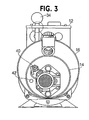
- FIG. 3 is a end view taken through line 3 - - 3 in FIG. 2.
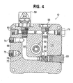
- FIG. 4 is a cross sectional view of an end head taken through line 4 - - 4 in FIG. 2.
- FIG. 5 is a cross sectional view diagrammatically illustrating a process of manufacture of the end head of FIG. 4, showing an overlay of a round tubing arrangement onto a conventional end head for representational purposes.
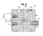
- FIG. 6 is a cross sectional view of an alternative end head arrangement formed in accordance with an embodiment of the present invention.
- FIG. 7 is a cross sectional view diagrammatically illustrating a process of manufacture of the end head of FIG. 6, showing an overlay of a round tubing arrangement onto a conventional end head for representational purposes.
- an end head and a method for making an end head are provided.
- One aspect of some embodiments of the invention is that at least some of the conduits in the end head are initially formed as bent tubing which is held in place during a molding manufacture of the end head block around the tubing.
- the tubing can reach the surface of the end head block to form ports, possibly with some tubing extended outward from the block to some degree immediately after the molding stage. At this point, the excess tubing extending outward from the block can be removed, and further port attachment threads can be drilled and tapped at the desired location of the ports.
- componentry such as operational valves, check valves and over pressure valves can be added to interact with the conduits at this stage so that the valves intersect with the conduits. Benefits of using tubing to form some or all of the conduit passageways include the ability to provide gradually curved directional changes in the conduit when bent tubing is used.
- Tubing also provides the ability to provide changing diameters of the conduits along their length, and the ability to have the conduit walls which interact with the pressurized fluid be made of the tubing material, which may have more desirable properties for this purpose then the material of the end head block itself. In many instances the process of molding around tubing results in a reduction in manufacturing costs.
- the material from which the block is molded is not directly subjected to the fluid pressure in the tubular conduits and thus if the tubing is of sufficient thickness, the block molding material be selected to be a material that have other desirable properties, for example such as being light weight. Preferred materials for molding the block around the tubing are described in more detail below.
- an end head 10 is provided for connecting a motor 12 to a pump 14 and hydraulic tank 16, all forming a power pack arrangement. Since the illustrated exemplary power pack arrangement is for vertical mounting, the tank 16 is configured to have a drain plug 18 and a filler port cap 20 where shown.
- the pump 14 draws fluid from the oil tank 16 through an inlet assembly tube 22 attached by a band clamp 24 to a suction cover 26 of the pump 14.
- the suction cover 26 provides the means for fluid to enter the pump 14 for pressurization.
- the inlet tube 22 is also associated with a magnet 28 for attracting metallic particles and a filter 30 for filtering the hydraulic oil or other fluid as it enters the inlet tubing 22.
- the pump 14 may be any suitable hydraulic pump such as for example a gear pump.
- the motor 12 has a splined output shaft which drives a similarly splined input shaft of the pump 14. Both splined shafts are connected by extending through a bore in the end head 10, preferably by a splined connection which is free to rotate through the central bore of the end head 10.
- a seal 32 may be provided to seal the central bore to prevent leakage of fluid towards the motor, and an O-ring 34 may be provided to seal the end of the fluid tank 16 against the adjacent surface of the end head 10.
- a handle 34 is provided to provide mechanical leverage against a operation valve 36.
- the pump 14 is configured to provide pressure into a port (not shown in FIGS. 1-3), on the end head and to accept return flow through one or more return flow ports 40 and 42 which are provided in the pump-facing surface of the end head 10.
- FIGS. 1-3 except for the end head 10, are conventional and known in the art.
- the end head 10 according to this embodiment differs from the prior art end head arrangements in at least one of several ways, including for example its internal structure, its material, and its method of manufacture.
- FIG. 4 illustrates a cross sectional view of the end head 10 taken through line 4 - - 4 in FIG. 2.
- the end head 10 includes a central coupling piece 50 which is shown as a separate component surrounded by a clearance in a bore of the end head 16.
- the coupling 50 has internal splines which meet with the splines on the drive shafts of the motor and pump, respectively, so that power can be transmitted through the end head 10 by rotation of the spline coupling 50.
- the pump 14 supplies fluid under pressure into an inlet port 52 which is indicated by a circle in the illustration.
- the inlet 52 is a port extending perpendicular to the direction of the drawing and out the surface of the end head 10 that faces the pump 14.
- pressure generated by the pump 14 enters a conduit the end head by passing into the inlet port 52 represented by the circle 52.
- the pressurized fluid is then normally supplied to a conduit 54 which has been formed by tubing as described herein.
- the completed end head 10 has a check valve 56 that has been installed into a drilled and threaded bore socket that has been drilled from the outside edge of the end head 10 after it has been molded.
- the end head 10 also includes a conduit 62 formed by tubing leading to an operational valve 58 which in this embodiment is a normally closed two-position manually operable valve. In the normally closed position, the operational valve 58 permits flow only out through the working port 60.
- the valve 58 is installed into a drilled and threaded bore socket that is drilled into the block after it has been molded at the location of where the tube is extending outward out of the block.
- an outlet port 60 has a machined shape for attachment to a pressure line. The outlet, or “working" port 60, provides the high pressure outlet flow and is connected to a line providing pressure to the cylinder of the actuating cylinder or ram or other hydraulic component to be actuated.
- the side walls of the conduits 54, 62 and 64 respectively are formed by tubing which was inserted into a mold for the end head block with the material 70 of the end head block molded around the tube.
- One benefit of this can be seen for example in the radiused curvature 72 indicated at a portion of conduit 64.
- a cap 74 is provided at an end of conduit 62 where tubing had originally exited the molded block 70.
- conduits 54 and 62 were fashioned from tubes that did not actually intersect each other, but which crossed each other while substantially adjacent to each other at their point of intersection has seen in this drawing view.
- the drilling process for the insertion of check valve 56 is with a large enough diameter so that if the tube for conduit 54 and a tube for conduit 62 are interconnected by the hole that is drilled for the check valve 56 and subsequently by the inserted valve 56 so that the conduits 54 and 62 do have fluid connection with each other through the check valve 56.
- FIG. 4 also illustrates a return-to-tank fitting location 74 leading to the return to tank port 66 which can be provided for additional return of the fluid from the actuator to the tank 16 as well as an optional return-to-tank fitting location 76 which has its own return to tank port 78 for the return of fluid from some other source when desired.
- the ports 74, 76 and 78 have been manufactured using conventional drilling techniques.
- FIG. 5 a layout view is shown, with a prior art end head cross section having a line T indicating a single piece of bent tubing.
- the intersection of conduits 62 and 64 is at a similar crossing point where the tubes cross adjacent to each other slightly spaced apart but have a diameter such that the drilling and insertion process for the operation valve 58 causes a fluid connection between the conduits 62 and 64 through the valve 58.
- the heavy line labeled T shows the shape of the center line of the bent tubing that is used to form the corresponding conduits shown in FIG. 4.
- the first step is the placing of the tubing having its center line labeled T into a mold having an outer shape similar to the outer shape of the desired end head 10.
- a mold material is molded and formed and solidified in the mold around the tubing.
- portions of the tubes labeled T1, T2 and T3 and T4 will be extending outside the side edges of the molded block.
- the extending tubular material can be cut off with conventional cutters. A procedure of drilling will effectively remove the tubing walls up to the depth that is drilled and permit the threaded insertion of the appropriate valves, fittings and/or caps.
- FIGS. 6 and 7 illustrate an alternative configuration of an end head 100.
- This end head 100 includes an inlet port 110 leading to a conduit 112 which has been formed by a tube which leads to a check valve 114, further leading to a conduit 116 which leads to the manual operation valve 120 which in this embodiment is a flow control valve as opposed to an on/off valve as in the embodiment in FIG. 4.
- the fluid power output location is at 122 when the valve 120 is closed.
- the valve 120 When the valve 120 is open, fluid is directed through a conduit 124 that has been formed by a tube, which leads to a second return inlet fitting 126 which has been formed by the conventional drilling process intersection, into the tube which forms the conduit 124 and these lead to a conduit 128 which is also formed with the tubular walls.
- the conduit 128 leads to a relief valve 130 which in the illustrated embodiment is an adjustable relief valve.
- a relief valve 130 When the relief valve 130 is subjected to a sufficient pressure allows relief flow back to the tank and through a port 132.
- the inlet port 110 and return-to-tank port 132 are drilled perpendicularly to the overall conduit plan in a fashion similar to the ports 52 and 66 of the embodiment of FIG. 4 respectively.
- FIG. 7 is a view of the type similar to FIG. 5 showing a tubing generally designated X which has portions X1, X2, X3 and X4 extending out the initially molded block.
- the tubes cross each other at the location of the operating valve 120 and when drilling is performed to provide the mounting location for 120 a fluid connection is provided between conduits 116 and 124 through the valve 120.
- these two tubes run parallel to each other and adj acent to each other in such a way that the drilling for the installation of the relief valve 130 is of such diameter to put both tubes in fluid communication via the installation of the relief valve so that conduits 128 and 112 are in fluid communication through the relief valve.
- FIG. 4 and FIG. 6 are described for illustrative purposes only, to give examples of sample configurations of circuitry and associated components and ports that can be provided by molding a block around tubing to form an end head.
- a single bent tube having a complex shape may be utilized, or several individual tubes each having a respective straight or bent shape may be used.
- the tubes may extend outward from the sides or other parts of the end head by any amount. In most cases it is preferred that the tubes do not themselves become filled with material during the molding process. However, where it is desirable to embed a part of a tube inside the block but have it not extend outward from the block during molding the tube may have its open end presealed in some fashion.
- the tubes may be selected from any suitable material, and factors involving the selection of tubing material may include the tube's formability, cost, suitability for use with the hydraulic fluid involved, machining ability, the use of removal when drilled, and the tubing material's ability to bond with the surrounding molded material. Plain steel tubing is preference in some embodiments.
- the molding material that is molded around the tubing may also be selected from any suitable material, and in a preferred embodiment may include a cast aluminum using an aluminum casting process from the Contech ® company.
- the tubing is preferably relatively this wall steel tubing. If molding pressures thereafter to deform the tubing, the tubing can be intemally pressurized to retain its shape during molding. Also, optionally a mechanical on metallurgical bond can be formed between the tubing and the block during molding, for example by coating the tubing with epoxy before molding or by surface treating the tubing such as by measuring it.
- some embodiments of the present invention provide the ability to manufacture a manifold wherein some or all of internal passages are formed by tubes having a structural material molded in a block (or inside the block) that other suitable shape around the tubes.
- Componentry such as fittings and valves around the periphery of the block to connect to the tubes may be formed by typical machining processes and subsequently installed, and additional passages may also be machined as desired.
- the valves or fittings or other components may be preattached to the tubing before the material is molded.
- all, substantially all, or some of the fluid contacting components may be preassembled so that the fluid conduit passageways and some or all of the associated fittings and componentry are connected as a unit. Then, the mold material can be molded around this unit to provide desired structural stability and/or a desired external shape for mounting to other components.
- the tubing may be made from a material that is removable after the molding process, chemically or otherwise, thus providing the ability not only to use the tubing to form passageways during the molding process, but also to subsequently remove the tubing if desired, still leaving remaining passageways corresponding to the former tubing locations.
Landscapes
- Engineering & Computer Science (AREA)
- Physics & Mathematics (AREA)
- Fluid Mechanics (AREA)
- Mechanical Engineering (AREA)
- General Engineering & Computer Science (AREA)
- Valve Housings (AREA)
- Fluid-Pressure Circuits (AREA)
- Shaping Metal By Deep-Drawing, Or The Like (AREA)
- Rigid Pipes And Flexible Pipes (AREA)
Applications Claiming Priority (2)
| Application Number | Priority Date | Filing Date | Title |
|---|---|---|---|
| US10/741,442 US20050133102A1 (en) | 2003-12-22 | 2003-12-22 | Hydraulic end head with internally cast hydraulic circuits |
| US741442 | 2003-12-22 |
Publications (2)
| Publication Number | Publication Date |
|---|---|
| EP1548290A2 true EP1548290A2 (fr) | 2005-06-29 |
| EP1548290A3 EP1548290A3 (fr) | 2005-11-02 |
Family
ID=34552807
Family Applications (1)
| Application Number | Title | Priority Date | Filing Date |
|---|---|---|---|
| EP04029604A Withdrawn EP1548290A3 (fr) | 2003-12-22 | 2004-12-14 | Couvercle hydraulique avec circuits hydrauliques intégrés obtenus par moulage |
Country Status (5)
| Country | Link |
|---|---|
| US (2) | US20050133102A1 (fr) |
| EP (1) | EP1548290A3 (fr) |
| CN (1) | CN1636648A (fr) |
| SG (1) | SG112995A1 (fr) |
| TW (1) | TW200523052A (fr) |
Families Citing this family (5)
| Publication number | Priority date | Publication date | Assignee | Title |
|---|---|---|---|---|
| CN101943188B (zh) | 2010-04-29 | 2013-08-21 | 上海人豪液压技术有限公司 | 采用组合式法兰控制盖板的紧凑型二通插装阀 |
| DE102015205543A1 (de) * | 2015-03-26 | 2016-09-29 | Robert Bosch Gmbh | Hydraulikblock für ein Hydroaggregat einer Bremsregelung einer hydraulischen Fahrzeugbremsanlage |
| US10465354B2 (en) * | 2016-12-15 | 2019-11-05 | Caterpillar Inc. | Hydraulic fluid systems for machine implements |
| DE102018126116A1 (de) * | 2018-10-19 | 2020-04-23 | Robert Bosch Gmbh | Hydraulischer Verteilerblock, hydraulisches Aggregat und Verfahren |
| DE102019208495A1 (de) * | 2019-06-12 | 2020-12-17 | Sms Group Gmbh | Hydraulische Steuereinrichtung im Walzwerksbau |
Family Cites Families (20)
| Publication number | Priority date | Publication date | Assignee | Title |
|---|---|---|---|---|
| GB884865A (en) * | 1959-10-12 | 1961-12-20 | Ass Elect Ind | Improvements in and relating to manifolds suitable for connection to a plurality of valves |
| US3360008A (en) * | 1964-10-07 | 1967-12-26 | Raymond Int Inc | Molded manifold construction and method of forming |
| US3683960A (en) * | 1970-11-19 | 1972-08-15 | Jerry Kirsch | Block manifold for fluid control systems and method of making the same |
| US3888297A (en) * | 1973-11-02 | 1975-06-10 | Canron Ltd | Method of producing ferrous castings with cast-in ferrous inserts |
| JPS555152A (en) * | 1978-06-28 | 1980-01-16 | Hitachi Ltd | Production of heat exchanger |
| JPS55139160A (en) * | 1979-04-16 | 1980-10-30 | Nikkei Giken:Kk | Internal chilling type casting method |
| CH648908A5 (de) * | 1980-12-11 | 1985-04-15 | Reishauer Ag | Verfahren zur herstellung eines verteilerblockes fuer fluessige oder gasfoermige arbeitsmedien. |
| JPS57146463A (en) * | 1981-03-06 | 1982-09-09 | Nippon Steel Corp | Manufacture of stave cooler |
| DE3129391C1 (de) * | 1981-07-25 | 1982-11-04 | Estel Hoesch Werke Ag, 4600 Dortmund | Verfahren zur Herstellung von Gusskoerpern mit eingegossenen Rohren aus Stahl |
| US4516594A (en) * | 1984-04-03 | 1985-05-14 | Diesel Equipment Limited | Multi-part valve with a valve seat skeleton and cast valve body |
| US4836246A (en) * | 1987-08-03 | 1989-06-06 | Colt Industries Inc. | Manifold for distributing a fluid and method for making same |
| US4865112A (en) * | 1988-07-07 | 1989-09-12 | Schwarb Foundry Company | Method of casting metals with integral heat exchange piping |
| FR2638809B1 (fr) * | 1988-11-09 | 1991-01-25 | Hutchinson | Bloc de jonction et de raccordement entre canalisations souples en materiau elastomere, son procede et son dispositif de fabrication |
| FR2665384B1 (fr) * | 1990-08-02 | 1992-10-16 | Montupet Sa | Procede de realisation d'une piece moulee en al ou ses alliages munie de canaux integres. |
| US5429175A (en) * | 1993-07-01 | 1995-07-04 | Tht Presses Inc. | Vertical die casting press and method of operation |
| US5660223A (en) * | 1995-11-20 | 1997-08-26 | Tht Presses Inc. | Vertical die casting press with indexing shot sleeves |
| BR9700242A (pt) * | 1997-02-14 | 1998-12-08 | Spirax Sarco Ind E Comercio Lt | Distribuidor de fluxo de fluido |
| US6257310B1 (en) * | 1999-08-19 | 2001-07-10 | Reliance Electric Technolgies, Llc | Method for making heat sink vacuum |
| JP3233358B2 (ja) * | 2000-01-14 | 2001-11-26 | 日本軽金属株式会社 | パイプの鋳ぐるみ方法 |
| JP4750305B2 (ja) * | 2001-04-09 | 2011-08-17 | ヤマハモーターハイドロリックシステム株式会社 | 船外機のチルト装置 |
-
2003
- 2003-12-22 US US10/741,442 patent/US20050133102A1/en not_active Abandoned
-
2004
- 2004-12-14 EP EP04029604A patent/EP1548290A3/fr not_active Withdrawn
- 2004-12-20 SG SG200407548A patent/SG112995A1/en unknown
- 2004-12-20 TW TW93139655A patent/TW200523052A/zh unknown
- 2004-12-22 CN CNA2004101017294A patent/CN1636648A/zh active Pending
-
2007
- 2007-12-14 US US11/957,011 patent/US20080092382A1/en not_active Abandoned
Also Published As
| Publication number | Publication date |
|---|---|
| TW200523052A (en) | 2005-07-16 |
| SG112995A1 (en) | 2005-07-28 |
| EP1548290A3 (fr) | 2005-11-02 |
| US20050133102A1 (en) | 2005-06-23 |
| CN1636648A (zh) | 2005-07-13 |
| US20080092382A1 (en) | 2008-04-24 |
Similar Documents
| Publication | Publication Date | Title |
|---|---|---|
| CN106004849B (zh) | 车辆液压制动设备的制动调节系统的液压总成的液压块 | |
| CN111075792B (zh) | 液压的分配块、液压设备和方法 | |
| US20080092382A1 (en) | Hydraulic end head with internally cast hydraulic circuits | |
| CN111779724B (zh) | 一种航空电静液作动系统用液压集成阀块 | |
| US8601997B2 (en) | Water pump with integrated oil cooler | |
| EP1108113B1 (fr) | Procedes et appareil de raccord de tubages utilisant une commande superieure | |
| EP3681774B1 (fr) | Bloc hydraulique pour un système de freinage hydraulique à actionnement par une force extérieure d'un véhicule | |
| EP4330091A1 (fr) | Bloc hydraulique pour une unité de freinage de service d'un système de servofrein hydraulique | |
| WO2019234725A1 (fr) | Système de collecteur à blocs alignés à 2 fentes | |
| US5740851A (en) | Component with cast-in fluid passageways | |
| CN111086267A (zh) | 液压的控制装置 | |
| CN1975164A (zh) | 复式泵装置 | |
| EP3267066A2 (fr) | Frein de support de roue à ressort appliqué et desserré hydrauliquement présentant un meilleur support de disque fixe | |
| CN107975509A (zh) | 行走马达集成阀盖及行走马达 | |
| CN1877174A (zh) | 阀芯和阀门装置 | |
| US5330139A (en) | Mounting apparatus for a fluid conduit assembly | |
| US5466052A (en) | A fluid connecting device | |
| US7293494B2 (en) | Expandable hydraulic valve stack | |
| CN119796157A (zh) | 用于机动车辆制动系统的具有适配器单元的制动操纵装置 | |
| JP2003508676A (ja) | メインユニットと少なくとも一つの付属機能ユニットを有する組み合わせ | |
| JP6606520B2 (ja) | 車両用ブレーキ液圧制御装置 | |
| JP5239803B2 (ja) | 成形品の流体通路構造およびオイルポンプ | |
| CN101208555B (zh) | 液压系统和包括该液压系统的液压控制装置 | |
| JPS6128481Y2 (fr) | ||
| US5341903A (en) | Fluid conduit arrangement |
Legal Events
| Date | Code | Title | Description |
|---|---|---|---|
| PUAI | Public reference made under article 153(3) epc to a published international application that has entered the european phase |
Free format text: ORIGINAL CODE: 0009012 |
|
| AK | Designated contracting states |
Kind code of ref document: A2 Designated state(s): AT BE BG CH CY CZ DE DK EE ES FI FR GB GR HU IE IS IT LI LT LU MC NL PL PT RO SE SI SK TR |
|
| AX | Request for extension of the european patent |
Extension state: AL BA HR LV MK YU |
|
| PUAL | Search report despatched |
Free format text: ORIGINAL CODE: 0009013 |
|
| AK | Designated contracting states |
Kind code of ref document: A3 Designated state(s): AT BE BG CH CY CZ DE DK EE ES FI FR GB GR HU IE IS IT LI LT LU MC NL PL PT RO SE SI SK TR |
|
| AX | Request for extension of the european patent |
Extension state: AL BA HR LV MK YU |
|
| RIC1 | Information provided on ipc code assigned before grant |
Ipc: 7B 29C 70/70 B Ipc: 7B 29C 39/10 B Ipc: 7B 29C 33/00 B Ipc: 7F 15B 13/00 B Ipc: 7F 15B 15/18 A |
|
| AKX | Designation fees paid | ||
| STAA | Information on the status of an ep patent application or granted ep patent |
Free format text: STATUS: THE APPLICATION IS DEEMED TO BE WITHDRAWN |
|
| 18D | Application deemed to be withdrawn |
Effective date: 20060503 |
|
| REG | Reference to a national code |
Ref country code: DE Ref legal event code: 8566 |