EP1548247A2 - Vehicle - Google Patents
Vehicle Download PDFInfo
- Publication number
- EP1548247A2 EP1548247A2 EP04022585A EP04022585A EP1548247A2 EP 1548247 A2 EP1548247 A2 EP 1548247A2 EP 04022585 A EP04022585 A EP 04022585A EP 04022585 A EP04022585 A EP 04022585A EP 1548247 A2 EP1548247 A2 EP 1548247A2
- Authority
- EP
- European Patent Office
- Prior art keywords
- filling
- motor vehicle
- vehicle according
- wall
- nozzle
- Prior art date
- Legal status (The legal status is an assumption and is not a legal conclusion. Google has not performed a legal analysis and makes no representation as to the accuracy of the status listed.)
- Granted
Links
- 238000005192 partition Methods 0.000 claims description 19
- 239000007788 liquid Substances 0.000 claims description 18
- 238000001816 cooling Methods 0.000 claims description 17
- 230000002093 peripheral effect Effects 0.000 claims description 2
- 230000000903 blocking effect Effects 0.000 claims 1
- 239000000945 filler Substances 0.000 description 4
- 238000002347 injection Methods 0.000 description 3
- 239000007924 injection Substances 0.000 description 3
- 230000004888 barrier function Effects 0.000 description 2
- 238000007789 sealing Methods 0.000 description 2
- 238000004026 adhesive bonding Methods 0.000 description 1
- 238000002485 combustion reaction Methods 0.000 description 1
- 239000002826 coolant Substances 0.000 description 1
- 239000000110 cooling liquid Substances 0.000 description 1
- 230000003292 diminished effect Effects 0.000 description 1
- 238000001746 injection moulding Methods 0.000 description 1
- 238000003466 welding Methods 0.000 description 1
Images

Classifications
-
- F—MECHANICAL ENGINEERING; LIGHTING; HEATING; WEAPONS; BLASTING
- F01—MACHINES OR ENGINES IN GENERAL; ENGINE PLANTS IN GENERAL; STEAM ENGINES
- F01P—COOLING OF MACHINES OR ENGINES IN GENERAL; COOLING OF INTERNAL-COMBUSTION ENGINES
- F01P11/00—Component parts, details, or accessories not provided for in, or of interest apart from, groups F01P1/00 - F01P9/00
- F01P11/02—Liquid-coolant filling, overflow, venting, or draining devices
- F01P11/0204—Filling
- F01P11/0209—Closure caps
- F01P11/0238—Closure caps with overpressure valves or vent valves
-
- F—MECHANICAL ENGINEERING; LIGHTING; HEATING; WEAPONS; BLASTING
- F01—MACHINES OR ENGINES IN GENERAL; ENGINE PLANTS IN GENERAL; STEAM ENGINES
- F01P—COOLING OF MACHINES OR ENGINES IN GENERAL; COOLING OF INTERNAL-COMBUSTION ENGINES
- F01P11/00—Component parts, details, or accessories not provided for in, or of interest apart from, groups F01P1/00 - F01P9/00
- F01P11/02—Liquid-coolant filling, overflow, venting, or draining devices
- F01P11/0204—Filling
- F01P11/0209—Closure caps
- F01P11/0247—Safety; Locking against opening
-
- F—MECHANICAL ENGINEERING; LIGHTING; HEATING; WEAPONS; BLASTING
- F01—MACHINES OR ENGINES IN GENERAL; ENGINE PLANTS IN GENERAL; STEAM ENGINES
- F01P—COOLING OF MACHINES OR ENGINES IN GENERAL; COOLING OF INTERNAL-COMBUSTION ENGINES
- F01P11/00—Component parts, details, or accessories not provided for in, or of interest apart from, groups F01P1/00 - F01P9/00
- F01P11/02—Liquid-coolant filling, overflow, venting, or draining devices
- F01P11/029—Expansion reservoirs
-
- F—MECHANICAL ENGINEERING; LIGHTING; HEATING; WEAPONS; BLASTING
- F01—MACHINES OR ENGINES IN GENERAL; ENGINE PLANTS IN GENERAL; STEAM ENGINES
- F01P—COOLING OF MACHINES OR ENGINES IN GENERAL; COOLING OF INTERNAL-COMBUSTION ENGINES
- F01P11/00—Component parts, details, or accessories not provided for in, or of interest apart from, groups F01P1/00 - F01P9/00
- F01P11/02—Liquid-coolant filling, overflow, venting, or draining devices
- F01P11/0204—Filling
- F01P11/0209—Closure caps
- F01P11/0247—Safety; Locking against opening
- F01P2011/0252—Venting before opening
Definitions
- the invention is based on a motor vehicle with a body, a via a cooling circuit with liquid cooled drive machine and with a Filling nozzle for the cooling circuit, according to the preamble of claim 1.
- a generic type motor vehicle with a filling nozzle for a cooling circuit is For example, see US Pat. No. 5,603,425.
- the filling nozzle has a Filling opening for the liquid and a removable cap for the Filling hole. So with hot, pressurized liquid when removing the Cap an uncontrolled squirting out of the liquid from the Filling nozzle is avoided, this is provided with an overflow nozzle, which before the complete removal of the cap is released, reducing the overpressure the cooling liquid can be removed via this overflow nozzle.
- Overflow is oriented away from the filler neck and can with be connected to a hose so that the exiting through the overflow pipe Liquid can flow away from the filling nozzle.
- a similar embodiment of a filling nozzle with a filling opening, a Closure cap and an overflow is also the DE 100 33 953 A1 to remove.
- the object of the invention is to provide a motor vehicle of the type mentioned, in which an improved protection for a person is achieved when the cap is removed with hot liquid of the cooling circuit.
- the releasing or closing of the Overflow nozzle achieved in a simple manner.
- Preferred is a variant according to claim 8, wherein in the Drip tray liquid can be discharged through the drain port.
- An embodiment with the features contained in claim 10 is characterized by a simple manufacturability. Here are filling, overflow and Drip tray aligned with each other so that they are produced in one piece, for example, by plastic injection molding, together from the injection mold can be removed from the mold.
- refilling the liquid allows without having access to the engine compartment.
- this is advantageous in vehicles where the prime mover is not directly accessible is, as given for example in motor vehicles with a mid-motor assembly.
- the vehicle interior is formed continuously and includes the passenger compartment and the luggage compartment, as this particular case Passenger car with a body in the form of a coupe with mid-engine is provided.
- the engine compartment In one of the vehicle compartments 6, 8, 9, the engine compartment, is a prime mover 10 of the Housed motor vehicle 1, in particular designed as an internal combustion engine is.
- the drive machine 10 in so-called.
- Mid motor arrangement in the motor vehicle 1 arranged in the vehicle compartment 8 and the vehicle spaces 6 and 9 form a rear and front luggage space. It would be However, conceivable without further ado, the prime mover 10 in the front vehicle compartment.
- the individual vehicle spaces 6, 7, 8 and 9 are surrounded by the walls 4 ', of which some are provided as partitions 11, 12 and 13 and two vehicle spaces 6, 7, 8, 9 from each other, wherein in front of an end wall or bulkhead 11 'the Partition wall 11 is arranged and with this between the vehicle compartments 6 and 7 lies.
- the bulkhead 11 ' may form another partition.
- the partition walls 11 ', 11, 12 and 13 are substantially upright or have at least one Wall section 14 which is substantially upright, that is approximately in the direction of Vehicle vertical axis FH runs.
- the engine 10 is cooled with liquid and therefore comprises a cooling circuit not shown here in detail, from which in FIGS and Fig. 3 shows only a filling nozzle 16.
- the filling nozzle 16 is here a Service unit 17 assigned in one of the vehicle spaces 6, 8 or 9 at one of the Walls 4 ', in particular one of the partitions 11, 12 or 13, is arranged. in the Embodiment, this is the partition wall 13 of the vehicle compartments 8 and 9.
- the service unit 17 next to the filling nozzle 16 includes a Oil filler 18 which is closed with a lid 19.
- the same or the same acting parts as shown in FIGS. 1 and 2 are provided with the same reference numerals.
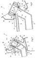
- the Filling nozzle 16 includes a filling opening 20 which is located in the vehicle compartment 9 and the a free end of a filling portion 21 of the filling nozzle 16 is formed, which filling section 21 into an angled thereto connecting portion 22nd passes to the not shown here cooling circuit of the engine 10th connected.
- a Overflow nozzle 24 which is located near the filling opening 20 and the filling section 21.
- the overflow pipe 24 is formed by a tubular extension which laterally from the filling nozzle 16 starts and has an inlet opening 25 in the tube wall 23. It runs approximately parallel to the connection section 22 of the filling nozzle 16. Der Inlet opening 25 opposite to the other end of the overflow nozzle 24 opens this in the adjacent to the vehicle compartment 9 vehicle compartment 8, so that the Filling opening 20 with respect to the partition wall 13 on a first side 26 and one of Inlet opening 25 opposite, end discharge opening 27 of the overflow nozzle 24 on the first side 26 opposite second side 28 of the partition 13th to come to rest.
- the filling opening 20 lies in another Vehicle compartment 6, 7, 8, 9 as the drain opening 27 of the overflow nozzle 24. In the shown Embodiment thus lies on the first side 26 of the partition 13 of the Vehicle space 9 and on the second side 28 of the partition wall 13 of the vehicle compartment. 8
- a Web plate 30 is provided, which the vehicle compartment 9 and the vehicle compartment. 7 subdivided, which could also be omitted, so that as well Passenger compartment designated vehicle compartment 7 and also as a luggage room used vehicle space 9 form a continuous vehicle interior 31.
- the filling nozzle 16 passes through it Terminal portion 22, the partition 13 in an opening 32. Similarly passes through the outgoing of the filling opening 20 of the filling nozzle 16 Overflow pipe 24, the partition 13 in a further breakthrough 33. Furthermore, FIG. 3 a closure cap 34 for the filling nozzle 16, sealing the filling opening 20 closes, for what an inner, for example tubular extension 35 outside a seal 36 is circumferentially mounted, with the inside 37 of the Tube wall 23 cooperates.
- the length LF of the extension 35 is dimensioned such that that this together with the seal 36, a shut-off means for the overflow pipe 24th forms, which extension 35 thus spaced from the filling opening 20 lying Overflow port 24 with its inlet opening 25 closes when the cap 34 is completely placed on the filler neck.
- a corresponding securing means 38 is provided be, which between the filling nozzle 16 cross-section of the Cap 34 and the outside 39 of the tube wall 23 is provided.
- This Securing means 38 can be designed in particular as a screw or bayonet closure be.
- Fig. 3 is dash-dotted yet a connecting piece 40 indicated that the partition 13th can prevail and with a possibly existing expansion tank of the cooling circuit and the filling nozzle 16 is connected.
- Tray 42 is formed when refilling liquid for the cooling circuit possibly spills liquid so that it does not enter the vehicle compartment 6, 7, 8 and 9, in which the filling nozzle 16 protrudes.
- the drip tray 42 is with Distance from the filling opening 20 in the direction of connection portion 22 set back, covered doing the overflow pipe 24 and also dominates with its bottom Collar portion 43, the overlying filling opening 20th
- drip tray 42 In order to be able to derive liquid collected in the drip tray 42, is - according to 3 - provided in the region of the lower collar portion 43, a drain port 44, the dash-dotted lines is indicated and in particular the partition wall 13 penetrates and so the liquid transported away in the room 8, so on the second page 28 in the Room 8 opens.
- drip tray 42 and drain port 44 are integral executed.
- the filling nozzle 16, the Overflow pipe 24 and the collecting tray 42 in one piece, for example as a plastic Injection molded part executed.
- connection section 22 and the filling section 21 runs at an angle to each other and the overflow nozzle, from the filling section 21 goes out, it runs approximately parallel to the connection section 22.
- the drip tray 42 with its shell wall, so the collar 41, in the direction of Einhellö réelle 20, so that the shell bottom 45 adjacent to the tube wall 23 of the Behellstutzens 16 is located and the shell peripheral wall 46, starting from the Shell bottom 45 extends substantially into the vehicle compartment 9, whereby the Collecting pan 42 possibly in one piece with the filling nozzle 16 and the overflow pipe 24th could be made. Possibly. can the drain port 44 and the connecting piece 40th be realized in one piece with the filling nozzle 16.
- the drip tray 42 may be inserted into a cowling 47 which is the divider 13 or the vehicle compartment 9 lines and that as a molded part and / or Carpeting can be performed.
- a service unit 17 of FIG. 4 is the Filling nozzle equipped with an extension 48, opposite to the rest Filling portion 21 is provided with a larger inner diameter of the tube 23.
- the Extension 48 has the filling opening 20 and carries the cap 34.
- the Extension 48 is formed by a step 49, which is the inner diameter of the tube 23 expands and forms a stepped bottom 50 in the filling section 20, which Tier floor serves as a sealing surface 51, which with the now on a fork-like Front end 52 of the extension 35 of the cap 34 cooperates and so the Barrier means for the overflow pipe 24 forms.
- At the end turn 52 is for receiving the Seal 36 an annular groove 53 is formed.
- the approximately inlet opening 25, which is approximately oval in Cross section may be when the overflow pipe 24 attaches tangentially to the pipe 23.
- the filling nozzle 16, overflow pipe 24 and possibly the connecting piece 40 can be integral with the collar 41.
- the drip tray 42 is thereby executed as a separate part and at a joint 54 with the collar 41st connected, for example by gluing or welding.
- the drip tray 42 is inserted into the cowling 47 and at least the overflow pipe 24 extends through the wall 4 '. Otherwise, in Fig. 4th the same or equivalent parts with the same reference numerals as in Figs. 1 to 3 Mistake.
- the filling nozzle 16 with its outgoing nozzle 24, 40 and 44 and the drip tray 42 made of plastic produced.
Abstract
Description
Bei der Erfindung wird ausgegangen von einem Kraftfahrzeug mit einer Karosserie, einer über einen Kühlkreis mit Flüssigkeit gekühlten Antriebsmaschine und mit einem Befüllstutzen für den Kühlkreis, gemäß Oberbegriff des Anspruchs 1.The invention is based on a motor vehicle with a body, a via a cooling circuit with liquid cooled drive machine and with a Filling nozzle for the cooling circuit, according to the preamble of claim 1.
Ein gattungsbildendes Kraftfahrzeug mit einem Befüllstutzen für einen Kühlkreis ist beispielsweise der US - A - 56 03 425 zu entnehmen. Der Befüllstutzen besitzt eine Einfüllöffnung für die Flüssigkeit und eine abnehmbare Verschlusskappe für die Einfüllöffnung. Damit bei heißer, unter Druck stehender Flüssigkeit beim Abnehmen der Verschlusskappe ein unkontrolliertes Herausspritzen der Flüssigkeit aus dem Befüllstutzen vermieden wird, ist dieser mit einem Überlaufstutzen versehen, der vor dem vollständigen Abnehmen der Verschlusskappe freigegeben wird, wodurch der Überdruck der Kühlflüssigkeit über diesen Überlaufstutzen abgebaut werden kann. Der Überlaufstutzen ist dabei von dem Befüllstutzen weggerichtet orientiert und kann mit einem Schlauch verbunden sein, so dass die über den Überlaufstutzen austretende Flüssigkeit vom Befüllstutzen entfernt abfließen kann.A generic type motor vehicle with a filling nozzle for a cooling circuit is For example, see US Pat. No. 5,603,425. The filling nozzle has a Filling opening for the liquid and a removable cap for the Filling hole. So with hot, pressurized liquid when removing the Cap an uncontrolled squirting out of the liquid from the Filling nozzle is avoided, this is provided with an overflow nozzle, which before the complete removal of the cap is released, reducing the overpressure the cooling liquid can be removed via this overflow nozzle. Of the Overflow is oriented away from the filler neck and can with be connected to a hose so that the exiting through the overflow pipe Liquid can flow away from the filling nozzle.
Eine ähnliche Ausgestaltung eines Befüllstutzens mit einer Einfüllöffnung, einer Verschlusskappe und einem Überlaufstutzen ist überdies der DE 100 33 953 A1 zu entnehmen.A similar embodiment of a filling nozzle with a filling opening, a Closure cap and an overflow is also the DE 100 33 953 A1 to remove.
Aufgabe der Erfindung ist es, ein Kraftfahrzeug der eingangs genannten Art anzugeben, bei dem ein verbesserter Schutz für eine Person erreicht ist, wenn die Verschlusskappe bei heißer Flüssigkeit des Kühlkreises abgenommen wird.The object of the invention is to provide a motor vehicle of the type mentioned, in which an improved protection for a person is achieved when the cap is removed with hot liquid of the cooling circuit.
Gelöst wird diese Aufgabe mit einem Kraftfahrzeug, welches die in Anspruch 1 genannten Merkmale umfasst. Weitere, die Erfindung ausgestaltende Merkmale sind in den Unteransprüchen angegeben. This object is achieved with a motor vehicle, which mentioned in claim 1 Features includes. Further, the invention ausgestaltende features are in the Subclaims specified.
Die mit der Erfindung hauptsächlich erzielten Vorteile sind darin zu sehen, dass durch die gegenüberliegende Anordnung von Einfüllöffnung des Befüllstutzens und Ablauföffnung des Überlaufstutzens an einer Wand der Karosserie durch die Wand selbst eine Barriere geschaffen wird, die die Gefahr eines ungewollten Kontaktes mit der aus dem Überlaufstutzen austretenden heißen Flüssigkeit mit einer Person zumindest vermindert, wenn die Verschlusskappe von dem Befüllstutzen abgenommen wird.The advantages achieved by the invention are to be seen in that opposite arrangement of filling opening of the filling nozzle and drain opening the overflow nozzle on a wall of the body by the wall itself a barrier created the risk of unwanted contact with the out of the Overflow nozzle escaping hot liquid with one person at least diminished when the cap is removed from the filling nozzle.
Mit den in Anspruch 4 genannten Merkmalen wird in vorteilhafter Weise erreicht, dass
beim Abnehmen der Verschlusskappe der Überlaufstutzen von dem Absperrmittel bereits
freigegeben wird, bevor die Verschlusskappe vollständig abgenommen ist, so dass sich
ein eventuell vorhandener Überdruck in dem Kühlkreis nicht über die Einfüllöffnung,
sondern über den Überlaufstutzen abbauen kann.With the features mentioned in
Bei einer Ausführungsform gemäß Anspruch 6 wird das Freigeben bzw. Verschließen des
Überlaufstutzens auf einfache Art und Weise erreicht.In one embodiment according to
Nach einer Weiterbildung der Erfindung mit den in Anspruch 7 genannten Merkmalen ist
vorteilhaft, dass beim Nachfüllen des Kühlkreises mit Flüssigkeit eventuell verschüttete
Flüssigkeit aufgefangen werden kann und somit umgebende Fahrzeugteile, beispielsweise
Verkleidungsteile, geschützt sind.According to a development of the invention with the features mentioned in
Bevorzugt wird eine Ausführungsvariante nach Anspruch 8, bei welcher in die
Auffangschale gelangte Flüssigkeit über den Abflussstutzen abgeleitet werden kann.Preferred is a variant according to
Ein Ausführungsbeispiel mit den in Anspruch 10 enthaltenen Merkmalen zeichnet sich
durch eine einfache Herstellbarkeit aus. Dabei sind Befüllstutzen, Überlaufstutzen und
Auffangschale so zueinander ausgerichtet, dass diese beim einstückigen Herstellen,
beispielsweise durch Kunststoff - Spritzgießen, gemeinsam aus der Spritzgießform
entformt werden können. An embodiment with the features contained in
Mit den Merkmalen des Anspruchs 12 kann ein Nachfüllen der Flüssigkeit ermöglicht
werden, ohne dabei Zugang zu dem Motorraum zu haben. Insbesondere ist dies
vorteilhaft bei Fahrzeugen, bei denen die Antriebsmaschine nicht unmittelbar zugänglich
ist, wie dies beispielsweise bei Kraftfahrzeugen mit Mittelmotoranordnung gegeben ist.With the features of
Entsprechend Anspruch 16 wird der Fahrzeuginnenraum durchgehend ausgebildet und
umfasst den Fahrgastraum und den Gepäckraum, wie dies insbesondere bei einem
Personenkraftwagen mit einer Karosserie in Form eines Coupés mit Mittelmotor
vorgesehen ist.According to
Die Erfindung wird nachfolgend anhand von Ausführungsbeispielen mit Bezug auf die Zeichnung näher erläutert.The invention will be described below with reference to embodiments with reference to the Drawing explained in more detail.
Es zeigen:
- Fig. 1
- schematisch in aufgeschnittener Seitenansicht ein Kraftfahrzeug als Personenwagen,
- Fig. 2
- ausschnittweise eine Serviceeinheit, die einen Befüllstutzen eines Kühlkreises einer Antriebsmaschine des Kraftfahrzeugs aufweist,
- Fig. 3
- in geschnittener (Schnittlinie III - III in Fig. 2) Detailansicht den Befüllstutzen mit einer Verschlusskappe und einem Überlaufstutzen nach einem ersten Ausführungsbeispiel der Serviceeinheit und
- Fig. 4
- in geschnittener Ansicht einen Befüllstutzen mit einer Verschlusskappe und einem Überlaufstutzen entsprechend einem zweiten Ausführungsbeispiel einer Serviceeinheit.
- Fig. 1
- schematically in cutaway side view of a motor vehicle as a passenger car,
- Fig. 2
- a section of a service unit, which has a filling nozzle of a cooling circuit of a drive machine of the motor vehicle,
- Fig. 3
- in cut (section line III - III in Fig. 2) detail view of the filling nozzle with a cap and an overflow nozzle according to a first embodiment of the service unit and
- Fig. 4
- in a sectional view of a filling nozzle with a cap and an overflow nozzle according to a second embodiment of a service unit.
Das in Fig. 1 parallel zur Fahrzeuglängsachse FL aufgeschnittene Kraftfahrzeug 1,
insbesondere ein Personenwagen, besitzt einen von Rädern 2 getragenen Aufbau 3 mit
einer Karosserie 4, die auf eine Bodengruppe 5 des Aufbaus 3 aufsetzt und die mehrere
Wände 4' umfasst, welche Wände 4' mehrere Fahrzeugräume 6, 7, 8 und 9 begrenzen. In
einem der Fahrzeugräume 6, 8, 9, dem Motorraum, ist eine Antriebsmaschine 10 des
Kraftfahrzeugs 1 untergebracht, die insbesondere als Brennkraftmaschine ausgebildet
ist. Im vorliegenden Ausführungsbeispiel ist die Antriebmaschine 10 in sog.
Mittelmotoranordnung in dem Kraftfahrzeug 1 in dem Fahrzeugraum 8 angeordnet und
die Fahrzeugräume 6 und 9 bilden einen hinteren und vorderen Gepäckraum. Es wäre
jedoch ohne weiteres denkbar, die Antriebsmaschine 10 im vorderen Fahrzeugraum 6
oder im hinteren Fahrzeugraum 9, also als Front- oder Heckmotor anzuordnen. Die
einzelnen Fahrzeugräume 6, 7, 8 und 9 sind von den Wänden 4' umgeben, von denen
einige als Trennwände 11, 12 und 13 vorgesehen sind und jeweils zwei Fahrzeugräume
6, 7, 8, 9 voneinander teilen, wobei vor einer Stirnwand bzw. Spritzwand 11' die
Trennwand 11 angeordnet ist und mit dieser zwischen den Fahrzeugräumen 6 und 7
liegt. Die Spritzwand 11' kann eine weitere Trennwand bilden. Die Trennwände 11', 11,
12 und 13 stehen im wesentlichen aufrecht bzw. besitzen zumindest einen
Wandabschnitt 14, der im wesentlichen aufrecht steht, also etwa in Richtung der
Fahrzeughochachse FH verläuft.The motor vehicle 1 cut open parallel to the vehicle longitudinal axis FL in FIG. 1,
in particular a passenger car, has a 3 supported by wheels 2 structure
a
An die Antriebsmaschine 10 ist noch eine Getriebeeinheit 15 angeflanscht, die im
gezeigten Ausführungsbeispiel - in Fahrtrichtung FR gesehen - hinter der
Antriebsmaschine 10 und in der gezeigten Ausführungsform unterhalb des Bodens 9' des
Fahrzeugraums 9 angeordnet ist. Die Antriebsmaschine 10 wird mit Flüssigkeit gekühlt
und umfasst daher einen hier nicht ausführlich gezeigten Kühlkreis, von dem in den Fig. 2
und 3 lediglich ein Befüllstutzen 16 dargestellt ist. Dem Befüllstutzen 16 ist hier eine
Serviceeinheit 17 zugeordnet, die in einem der Fahrzeugräume 6, 8 oder 9 an einer der
Wände 4', insbesondere einer der Trennwände 11, 12 oder 13, angeordnet ist. Im
Ausführungsbeispiel ist dies die Trennwand 13 der Fahrzeugräume 8 und 9.
Beispielsweise umfasst die Serviceeinheit 17 neben dem Befüllstutzen 16 einen
Öleinfüllstutzen 18 der mit einem Deckel 19 verschlossen ist.To the
Anhand eines ersten Ausführungsbeispiel der Serviceeinheit 17 wird im folgenden der
Befüllstutzen 16 anhand von Fig. 3 näher erläutert, wobei in Fig. 3 gleiche bzw. gleich
wirkende Teile wie in den Fig. 1 und 2 mit denselben Bezugszeichen versehen sind. Der
Befüllstutzen 16 umfasst eine Einfüllöffnung 20, die im Fahrzeugraum 9 liegt und die an
einem freien Ende eines Einfüllabschnitts 21 des Befüllstutzens 16 ausgebildet ist,
welcher Einfüllabschnitt 21 in einen abgewinkelt dazu verlaufenden Anschlussabschnitt 22
übergeht, der an den hier nicht dargestellten Kühlkreis der Antriebsmaschine 10
angeschlossen ist. Von dem Befüllstutzen 16 mit seiner Rohrwand 23 geht ein
Überlaufstutzen 24 aus, der nahe der Einfüllöffnung 20 und am Einfüllabschnitt 21 liegt.
Der Überlaufstutzen 24 wird von einem rohrförmigen Fortsatz gebildet, der seitlich von
dem Befüllstutzen 16 ausgeht und eine Einlassöffnung 25 in der Rohrwand 23 aufweist.
Er verläuft etwa parallel zum Anschlussabschnitt 22 des Befüllstutzens 16. Der
Einlassöffnung 25 gegenüberliegend am anderen Ende des Überlaufstutzens 24 mündet
dieser in den an den Fahrzeugraum 9 angrenzenden Fahrzeugraum 8, so dass die
Einfüllöffnung 20 bezüglich der Trennwand 13 auf einer ersten Seite 26 und eine der
Einlassöffnung 25 gegenüberliegende, endseitige Ablauföffnung 27 des Überlaufstutzens
24 an der der ersten Seite 26 gegenüberliegenden zweiten Seite 28 der Trennwand 13
zu liegen kommt. Mit anderen Worten: die Einfüllöffnung 20 liegt in einem anderen
Fahrzeugraum 6, 7, 8, 9 als die Ablauföffnung 27 des Überlaufstutzens 24. Im gezeigten
Ausführungsbeispiel liegt somit auf der ersten Seite 26 der Trennwand 13 der
Fahrzeugraum 9 und auf der zweiten Seite 28 der Trennwand 13 der Fahrzeugraum 8.With reference to a first embodiment of the
In Fig. 1 ist zwischen Fahrzeugaußenhaut 29 und der aufrechten Trennwand 13 noch ein
Stegblech 30 vorgesehen, welches den Fahrzeugraum 9 und den Fahrzeugraum 7
unterteilt, welches jedoch auch weggelassen werden könnte, so dass der auch als
Fahrgastraum bezeichnete Fahrzeugraum 7 und der auch als Gepäckraum zu
verwendende Fahrzeugraum 9 einen durchgehenden Fahrzeuginnenraum 31 bilden.In Fig. 1 between the vehicle
Wie in Fig. 3 weiter zu sehen ist, durchsetzt der Befüllstutzen 16 mit seinem
Anschlussabschnitt 22 die Trennwand 13 in einem Durchbruch 32. In ähnlicher Weise
durchsetzt der nach der Einfüllöffnung 20 von dem Befüllstutzen 16 ausgehende
Überlaufstutzen 24 die Trennwand 13 in einem weiteren Durchbruch 33. Ferner zeigt Fig.
3 eine Verschlusskappe 34 für den Befüllstutzen 16, die die Einfüllöffnung 20 dichtend
verschließt, wofür an einem inneren, beispielsweise rohrförmigen Fortsatz 35
außenliegend eine Dichtung 36 umlaufend angebracht ist, die mit der Innenseite 37 der
Rohrwand 23 zusammenwirkt. Die Länge LF des Fortsatzes 35 ist dabei so bemessen,
dass dieser zusammen mit der Dichtung 36 ein Absperrmittel für den Überlaufstutzen 24
bildet, welcher Fortsatz 35 mithin den beabstandet zur Einfüllöffnung 20 liegenden
Überlaufstutzen 24 mit seiner Einlassöffnung 25 verschließt, wenn die Verschlusskappe
34 auf den Befüllstutzen vollständig aufgesetzt ist. Zum Befestigen der Verschlusskappe
34 auf dem Befüllstutzen 16 kann ein entsprechendes Sicherungsmittel 38 vorgesehen
sein, welches zwischen dem den Befüllstutzen 16 übergreifenden Abschnitt der
Verschlusskappe 34 und der Außenseite 39 der Rohrwand 23 vorgesehen ist. Dieses
Sicherungsmittel 38 kann insbesondere als Schraub- oder Bajonettverschluss ausgebildet
sein. Beim Abnehmen der Verschlusskappe 34 von dem Befüllstutzen 16 gibt somit der
Fortsatz 35 die Einlassöffnung 25 frei, so dass die eventuell in dem Kühlkreis unter Druck
stehende heiße Flüssigkeit in den Übelaufstutzen 24 eintreten, über diesen weggerichtet
von dem Befüllstutzen 16 auf die zweite Seite 28 der Trennwand 13 geführt und dort in
den beispielsweise unten offenen Motorraum abgeleitet werden kann. Denkbar wäre es,
an die Ablauföffnung 27 des Überlaufstutzens 24 eine Verlängerung, beispielsweise in
Form eines Schlauches o. ä. anzusetzen. Durch den Überlaufstutzen 24 kann somit beim
Abnehmen der Verschlusskappe 34 Überdruck innerhalb des Kühlkreises abgebaut
werden, so dass aus der Einfüllöffnung 20 keine Kühlflüssigkeit austritt. Erst nach
vollständigem Abnehmen der Verschlusskappe 34, wenn der Überdruck abgebaut ist,
kann ein Befüllen des Kühlkreises über den Befüllstutzen 16 erfolgen. In Fig. 3 ist
strichpunktiert noch ein Verbindungsstutzen 40 angedeutet, der die Trennwand 13
durchsetzen kann und mit einem ggf. vorhandenen Ausgleichsbehälter des Kühlkreises
und dem Befüllstutzen 16 verbunden ist.As can be seen further in FIG. 3, the
Um die Einfüllöffnung 20 bzw. um die Außenseite 30 der Rohrwand 23 des Befüllstutzens
16 ist ein zumindest teilweise um den Befüllstutzen 16 umlaufender Kragen 41 als
Auffangschale 42 ausgebildet, die beim Nachfüllen von Flüssigkeit für den Kühlkreis
eventuell verschüttete Flüssigkeit auffängt, so dass diese nicht in den Fahrzeugraum 6,
7, 8 bzw. 9 gelangt, in den der Befüllstutzen 16 hineinragt. Die Auffangschale 42 ist mit
Abstand zur Einfüllöffnung 20 in Richtung Anschlussabschnitt 22 zurückversetzt, verdeckt
dabei den Überlaufstutzen 24 und überragt außerdem mit ihrem unten liegenden
Kragenabschnitt 43 die darüber liegende Einfüllöffnung 20.To the filling
Um in der Auffangschale 42 aufgefangene Flüssigkeit ableiten zu können, ist - gemäß
Fig. 3 - im Bereich des unteren Kragenabschnittes 43 ein Abflussstutzen 44 vorgesehen,
der strichpunktiert angedeutet ist und insbesondere die Trennwand 13 durchdringt und
so die Flüssigkeit in den Raum 8 abtransportiert, also auf der zweiten Seite 28 in den
Raum 8 mündet. Vorzugsweise sind Auffangschale 42 und Abflussstutzen 44 einstückig
ausgeführt. In besonders bevorzugter Ausführungsform sind der Befüllstutzen 16, der
Überlaufstutzen 24 und die Auffangschale 42 einstückig, beispielsweise als Kunststoff -
Spritzgießteil ausgeführt. Um das fertige einstückige Teil, bestehend aus Befüllstutzen
16, Überlaufstutzen 24 und vorzugsweise Auffangschale 42, aus der Spitzgießform
entformen zu können, verläuft der Anschlussabschnitt 22 und der Einfüllabschnitt 21
unter einem Winkel zueinander und der Überlaufstutzen, der von dem Einfüllabschnitt 21
ausgeht, verläuft dabei etwa parallel zum Anschlussabschnitt 22. Außerdem erstreckt
sich die Auffangschale 42 mit ihrer Schalenwand, also dem Kragen 41, in Richtung zur
Einfüllöffnung 20, so dass also der Schalenboden 45 benachbart zur Rohrwand 23 des
Befüllstutzens 16 liegt und die Schalenumfangswand 46 sich ausgehend von dem
Schalenboden 45 im wesentlichen in den Fahrzeugraum 9 hinein erstreckt, wodurch die
Auffangschale 42 ggf. einstückig mit dem Befüllstutzen 16 und dem Überlaufstutzen 24
gefertigt sein könnte. Ggf. kann der Abflussstutzen 44 und der Verbindungsstutzen 40
einstückig mit dem Befüllstutzen 16 realisiert sein.In order to be able to derive liquid collected in the
Die Auffangschale 42 kann in ein Verkleidungsteil 47 eingesetzt sein, das die Trennwand
13 bzw. den Fahrzeugraum 9 auskleidet und das als Formteil und/oder
Teppichverkleidung ausgeführt sein kann. The
Nach einem weiteren Ausführungsbeispiel einer Serviceeinheit 17 gemäß Fig. 4 ist der
Befüllstutzen mit einer Erweiterung 48 ausgestattet, die gegenüber dem übrigen
Einfüllabschnitt 21 mit einem größeren Innendurchmesser des Rohr 23 versehen ist. Die
Erweiterung 48 weist die Einfüllöffnung 20 auf und trägt die Verschlusskappe 34. Die
Erweiterung 48 wird durch eine Stufe 49 gebildet, die den Innendurchmesser des Rohrs
23 erweitert und die einen Stufenboden 50 in dem Einfüllabschnitt 20 bildet, welcher
Stufenboden als Dichtfläche 51 dient, die mit der nunmehr an einem gabelartigen
Stirnende 52 des Fortsatzes 35 der Verschlusskappe 34 zusammenwirkt und so das
Absperrmittel für den Überlaufstutzen 24 bildet. Am Stirnwende 52 ist zur Aufnahme der
Dichtung 36 eine Ringnut 53 ausgebildet. Oberhalb des Stufenbodens 50, also
benachbart zur Einfüllöffnung 20, liegt die etwa Einlassöffnung 25, die etwa oval im
Querschnitt sein kann, wenn der Überlaufstutzen 24 tangential an das Rohr 23 ansetzt.According to another embodiment of a
Der Befüllstutzen 16, Überlaufstutzen 24 und ggf. der Verbindungsstutzen 40 können
zusammen mit dem Kragen 41 einstückig ausgeführt sein. Die Auffangschale 42 wird
dabei als separates Teil ausgeführt und an einer Fügestelle 54 mit dem Kragen 41
verbunden, beispielsweise durch Klebung oder Schweißung. Wie im Zusammenhang mit
Fig. 3 bereits erläutert, wird die Auffangschale 42 in das Verkleidungsteil 47 eingesetzt
und zumindest der Überlaufstutzen 24 durchragt die Wand 4'. Im übrigen sind in Fig. 4
gleiche bzw. gleichwirkende Teile mit denselben Bezugszeichen wie in den Fig. 1 bis 3
versehen. In den Ausführungsbeispielen sind der Befüllstutzen 16 mit seinen davon
ausgehenden Stutzen 24, 40 und 44 und die Auffangschale 42 aus Kunststoff
hergestellt.The filling
Claims (16)
Applications Claiming Priority (2)
| Application Number | Priority Date | Filing Date | Title |
|---|---|---|---|
| DE10359767 | 2003-12-19 | ||
| DE10359767A DE10359767B4 (en) | 2003-12-19 | 2003-12-19 | motor vehicle |
Publications (3)
| Publication Number | Publication Date |
|---|---|
| EP1548247A2 true EP1548247A2 (en) | 2005-06-29 |
| EP1548247A3 EP1548247A3 (en) | 2012-02-01 |
| EP1548247B1 EP1548247B1 (en) | 2014-03-26 |
Family
ID=34530337
Family Applications (1)
| Application Number | Title | Priority Date | Filing Date |
|---|---|---|---|
| EP04022585.6A Active EP1548247B1 (en) | 2003-12-19 | 2004-09-22 | Vehicle |
Country Status (4)
| Country | Link |
|---|---|
| US (1) | US7172089B2 (en) |
| EP (1) | EP1548247B1 (en) |
| JP (1) | JP4063819B2 (en) |
| DE (1) | DE10359767B4 (en) |
Families Citing this family (6)
| Publication number | Priority date | Publication date | Assignee | Title |
|---|---|---|---|---|
| JP4455924B2 (en) * | 2004-04-21 | 2010-04-21 | 株式会社パイオラックス | Pipe fitting |
| DE102004058327A1 (en) | 2004-12-03 | 2006-06-08 | Dr.Ing.H.C. F. Porsche Ag | Filling nozzle for a cooling circuit of a drive machine and motor vehicle with such a filler neck |
| DE102005021457B4 (en) | 2005-05-10 | 2007-02-08 | Dr.Ing.H.C. F. Porsche Ag | Service unit for supplementing equipment |
| DE102005021456B4 (en) * | 2005-05-10 | 2007-02-08 | Dr.Ing.H.C. F. Porsche Ag | Service unit for supplementing equipment |
| DE102007051022A1 (en) * | 2007-10-25 | 2009-04-30 | Bayerische Motoren Werke Aktiengesellschaft | Vehicle-air conditioning system, has cooling medium cable connector and locking cap aligned with each other to loosen or remove cap from cable connector for plastic deformation of cap and/or for breaking predetermined breaking point in cap |
| FR2964148A1 (en) * | 2010-08-30 | 2012-03-02 | Peugeot Citroen Automobiles Sa | DEGASSING BOX FOR THE COOLING SYSTEM OF A THERMAL MOTOR OF A MOTOR VEHICLE |
Citations (4)
| Publication number | Priority date | Publication date | Assignee | Title |
|---|---|---|---|---|
| JPS6033125A (en) | 1983-08-02 | 1985-02-20 | Nissan Motor Co Ltd | Reservoir tank |
| US5603425A (en) | 1995-03-17 | 1997-02-18 | Western Thomson Controls Limited | Radiator cap |
| DE10013746A1 (en) | 1999-03-30 | 2000-10-05 | Denso Corp | Filling connection for radiator, detachably connected to pouring-in connection of collecting container, horizontal line and filling cap |
| DE10033953A1 (en) | 1999-07-14 | 2001-02-15 | Denso Corp | Sealed container esp for engine cooling water has neck with inner wall forming injection port and outer wall with threaded surface for cap |
Family Cites Families (17)
| Publication number | Priority date | Publication date | Assignee | Title |
|---|---|---|---|---|
| US1685918A (en) * | 1924-05-31 | 1928-10-02 | Karmazin John | Condenser |
| US3071285A (en) * | 1959-10-07 | 1963-01-01 | Stant Mfg Company Inc | Depressed pressure cap |
| US3062400A (en) * | 1960-05-03 | 1962-11-06 | Reuben J Humbert | Safety valved pressure caps |
| JPS5029517U (en) * | 1973-07-13 | 1975-04-03 | ||
| US3910451A (en) * | 1973-10-01 | 1975-10-07 | Arthur P Tusing | Radiator cap |
| SE417123B (en) * | 1974-06-27 | 1981-02-23 | Walter C Avrea | DEVICE ON A LOCK FOR CONNECTION OF A COOLER'S REFILLING NECK |
| US4185751A (en) * | 1978-07-31 | 1980-01-29 | Stant Manufacturing Company, Inc. | Radiator cap |
| DE8901826U1 (en) * | 1988-11-23 | 1989-04-06 | Reutter Metallwarenfabrik Gmbh, 7050 Waiblingen, De | |
| GB2240096A (en) * | 1990-01-20 | 1991-07-24 | Ford Motor Co | End fitting for a fuel filler pipe |
| US5248052A (en) * | 1992-07-31 | 1993-09-28 | Mellinger Larry L | Apparatus for automatically releasing the super-atmospheric pressure of an engine cooling system in response to turning off the engine and preventing the buildup of pressure while the engine is off |
| BR9507812A (en) * | 1994-06-01 | 1997-09-16 | Heinrich Reutter | Closing lid can be fixed on a container nozzle |
| US5522456A (en) * | 1994-06-22 | 1996-06-04 | Geiger Technic, Inc. | Overflow with threaded plastic fillneck for surge tanks and overflow reservoirs |
| SE511623C2 (en) * | 1997-02-12 | 1999-11-01 | Saab Automobile | Device for fuel systems in a vehicle |
| DE19718594B4 (en) * | 1997-05-02 | 2007-03-22 | Audi Ag | Passenger vehicle with a hood |
| DE19753597A1 (en) * | 1997-12-03 | 1999-06-24 | Heinrich Reutter | Closure cover for automotive radiators |
| US6276312B1 (en) * | 1998-11-06 | 2001-08-21 | Stant Manufacturing Inc. | Thermal control cooling system vacuum valve |
| DE19923775A1 (en) * | 1999-05-22 | 2000-11-23 | Heinrich Reutter | Closing cal for vehicle radiator, with initial pressure of valve body against seal seat adjustable by controlled drive |
-
2003
- 2003-12-19 DE DE10359767A patent/DE10359767B4/en not_active Expired - Fee Related
-
2004
- 2004-09-22 EP EP04022585.6A patent/EP1548247B1/en active Active
- 2004-12-16 US US11/012,241 patent/US7172089B2/en active Active
- 2004-12-16 JP JP2004364958A patent/JP4063819B2/en not_active Expired - Fee Related
Patent Citations (4)
| Publication number | Priority date | Publication date | Assignee | Title |
|---|---|---|---|---|
| JPS6033125A (en) | 1983-08-02 | 1985-02-20 | Nissan Motor Co Ltd | Reservoir tank |
| US5603425A (en) | 1995-03-17 | 1997-02-18 | Western Thomson Controls Limited | Radiator cap |
| DE10013746A1 (en) | 1999-03-30 | 2000-10-05 | Denso Corp | Filling connection for radiator, detachably connected to pouring-in connection of collecting container, horizontal line and filling cap |
| DE10033953A1 (en) | 1999-07-14 | 2001-02-15 | Denso Corp | Sealed container esp for engine cooling water has neck with inner wall forming injection port and outer wall with threaded surface for cap |
Also Published As
| Publication number | Publication date |
|---|---|
| JP2005180445A (en) | 2005-07-07 |
| US7172089B2 (en) | 2007-02-06 |
| DE10359767B4 (en) | 2006-01-19 |
| EP1548247B1 (en) | 2014-03-26 |
| JP4063819B2 (en) | 2008-03-19 |
| EP1548247A3 (en) | 2012-02-01 |
| DE10359767A1 (en) | 2005-07-14 |
| US20050133112A1 (en) | 2005-06-23 |
Similar Documents
| Publication | Publication Date | Title |
|---|---|---|
| DE602004006659T2 (en) | Device for controlling crankshaft gas | |
| EP1766207B1 (en) | Oil/coolant module with coolant treatment system | |
| DE102009010282B4 (en) | Dry sump oil tank assembly for a vehicle | |
| DE102005051263A1 (en) | Oil tank arrangement with dry sump | |
| EP2221097B1 (en) | Filter device for hydrocarbon adsorption | |
| EP0925428B1 (en) | Subassembly for an internal combustion engine | |
| DE102006032205A1 (en) | Heat exchanger with coupling connection and coupling connection | |
| DE102017206251B3 (en) | Water tank device for an internal combustion engine with water injection | |
| DE10359767B4 (en) | motor vehicle | |
| DE19907264C1 (en) | Air intake silencer with water separator | |
| DE3204493A1 (en) | DEVICE FOR FORMING A WATER CASE AND AN EXPANSION VESSEL FOR A HEAT EXCHANGER | |
| DE102009055138B4 (en) | Oil pan with a bottom section offset upwards | |
| DE4023094A1 (en) | Vehicle plastics fuel tank - has filling pipe and bent pipes with normal operation and tank filling vent pipes formed integral with either side of filling pipe | |
| EP1498582B1 (en) | Oil filter and oil separator module for combustion engine | |
| DE3225929C2 (en) | Fuel tanks for internal combustion engines, in particular motor vehicles | |
| DE19923098C2 (en) | Coolers for internal combustion engines | |
| EP1666706B1 (en) | Filler neck for a cooling circuit of an engine and a vehicle having such filler neck | |
| DE602004003915T2 (en) | COOLING CIRCUIT FOR A PASSENGER CAR AND THE APPROPRIATE PASSENGER CAR | |
| DE19725336A1 (en) | Cooling system for battery of motor vehicle provided with IC engine | |
| DE2840813C2 (en) | Cooler with vertical cooling tubes and a ventilation device | |
| WO2003035438A1 (en) | Modular device for cleaning the windscreen of a motor vehicle | |
| DE19806610A1 (en) | Device for cooling air charging of charge air cooler of motor vehicle's internal combustion engine | |
| DE10136971A1 (en) | Lubricant container for dry sump lubrication fitted to engine in modular form for ease of removal and refitting | |
| DE102017010286A1 (en) | Expansion tank for the cooling system of a liquid-cooled internal combustion engine | |
| DE3127986A1 (en) | Gas separator for the liquid of a cooling circuit |
Legal Events
| Date | Code | Title | Description |
|---|---|---|---|
| PUAI | Public reference made under article 153(3) epc to a published international application that has entered the european phase |
Free format text: ORIGINAL CODE: 0009012 |
|
| AK | Designated contracting states |
Kind code of ref document: A2 Designated state(s): AT BE BG CH CY CZ DE DK EE ES FI FR GB GR HU IE IT LI LU MC NL PL PT RO SE SI SK TR |
|
| AX | Request for extension of the european patent |
Extension state: AL HR LT LV MK |
|
| RAP1 | Party data changed (applicant data changed or rights of an application transferred) |
Owner name: DR. ING. H.C. F. PORSCHE AKTIENGESELLSCHAFT |
|
| RAP1 | Party data changed (applicant data changed or rights of an application transferred) |
Owner name: DR. ING. H.C. F. PORSCHE AKTIENGESELLSCHAFT |
|
| RAP1 | Party data changed (applicant data changed or rights of an application transferred) |
Owner name: DR. ING. H.C. F. PORSCHE AG |
|
| PUAL | Search report despatched |
Free format text: ORIGINAL CODE: 0009013 |
|
| AK | Designated contracting states |
Kind code of ref document: A3 Designated state(s): AT BE BG CH CY CZ DE DK EE ES FI FR GB GR HU IE IT LI LU MC NL PL PT RO SE SI SK TR |
|
| AX | Request for extension of the european patent |
Extension state: AL HR LT LV MK |
|
| RIC1 | Information provided on ipc code assigned before grant |
Ipc: F01P 11/02 20060101AFI20111227BHEP |
|
| 17P | Request for examination filed |
Effective date: 20120801 |
|
| AKX | Designation fees paid |
Designated state(s): DE FR GB IT SE |
|
| 17Q | First examination report despatched |
Effective date: 20120918 |
|
| GRAP | Despatch of communication of intention to grant a patent |
Free format text: ORIGINAL CODE: EPIDOSNIGR1 |
|
| INTG | Intention to grant announced |
Effective date: 20130326 |
|
| GRAP | Despatch of communication of intention to grant a patent |
Free format text: ORIGINAL CODE: EPIDOSNIGR1 |
|
| INTG | Intention to grant announced |
Effective date: 20130906 |
|
| GRAS | Grant fee paid |
Free format text: ORIGINAL CODE: EPIDOSNIGR3 |
|
| GRAA | (expected) grant |
Free format text: ORIGINAL CODE: 0009210 |
|
| AK | Designated contracting states |
Kind code of ref document: B1 Designated state(s): DE FR GB IT SE |
|
| REG | Reference to a national code |
Ref country code: GB Ref legal event code: FG4D Free format text: NOT ENGLISH |
|
| REG | Reference to a national code |
Ref country code: DE Ref legal event code: R096 Ref document number: 502004014564 Country of ref document: DE Effective date: 20140430 |
|
| PG25 | Lapsed in a contracting state [announced via postgrant information from national office to epo] |
Ref country code: SE Free format text: LAPSE BECAUSE OF FAILURE TO SUBMIT A TRANSLATION OF THE DESCRIPTION OR TO PAY THE FEE WITHIN THE PRESCRIBED TIME-LIMIT Effective date: 20140326 |
|
| REG | Reference to a national code |
Ref country code: DE Ref legal event code: R097 Ref document number: 502004014564 Country of ref document: DE |
|
| PLBE | No opposition filed within time limit |
Free format text: ORIGINAL CODE: 0009261 |
|
| STAA | Information on the status of an ep patent application or granted ep patent |
Free format text: STATUS: NO OPPOSITION FILED WITHIN TIME LIMIT |
|
| 26N | No opposition filed |
Effective date: 20150106 |
|
| PG25 | Lapsed in a contracting state [announced via postgrant information from national office to epo] |
Ref country code: IT Free format text: LAPSE BECAUSE OF FAILURE TO SUBMIT A TRANSLATION OF THE DESCRIPTION OR TO PAY THE FEE WITHIN THE PRESCRIBED TIME-LIMIT Effective date: 20140326 |
|
| REG | Reference to a national code |
Ref country code: DE Ref legal event code: R097 Ref document number: 502004014564 Country of ref document: DE Effective date: 20150106 |
|
| REG | Reference to a national code |
Ref country code: FR Ref legal event code: PLFP Year of fee payment: 13 |
|
| REG | Reference to a national code |
Ref country code: FR Ref legal event code: PLFP Year of fee payment: 14 |
|
| REG | Reference to a national code |
Ref country code: FR Ref legal event code: PLFP Year of fee payment: 15 |
|
| PGFP | Annual fee paid to national office [announced via postgrant information from national office to epo] |
Ref country code: FR Payment date: 20190926 Year of fee payment: 16 |
|
| PGFP | Annual fee paid to national office [announced via postgrant information from national office to epo] |
Ref country code: GB Payment date: 20190920 Year of fee payment: 16 |
|
| GBPC | Gb: european patent ceased through non-payment of renewal fee |
Effective date: 20200922 |
|
| PG25 | Lapsed in a contracting state [announced via postgrant information from national office to epo] |
Ref country code: FR Free format text: LAPSE BECAUSE OF NON-PAYMENT OF DUE FEES Effective date: 20200930 |
|
| PG25 | Lapsed in a contracting state [announced via postgrant information from national office to epo] |
Ref country code: GB Free format text: LAPSE BECAUSE OF NON-PAYMENT OF DUE FEES Effective date: 20200922 |
|
| P01 | Opt-out of the competence of the unified patent court (upc) registered |
Effective date: 20230526 |
|
| PGFP | Annual fee paid to national office [announced via postgrant information from national office to epo] |
Ref country code: DE Payment date: 20230728 Year of fee payment: 20 |